EP3246694A1 - Gas analysis device, control system and control assistance system for combustion equipment, and gas analysis method - Google Patents
Gas analysis device, control system and control assistance system for combustion equipment, and gas analysis method Download PDFInfo
- Publication number
- EP3246694A1 EP3246694A1 EP15887752.2A EP15887752A EP3246694A1 EP 3246694 A1 EP3246694 A1 EP 3246694A1 EP 15887752 A EP15887752 A EP 15887752A EP 3246694 A1 EP3246694 A1 EP 3246694A1
- Authority
- EP
- European Patent Office
- Prior art keywords
- gas
- distribution
- standard
- furnace
- measurement
- Prior art date
- Legal status (The legal status is an assumption and is not a legal conclusion. Google has not performed a legal analysis and makes no representation as to the accuracy of the status listed.)
- Withdrawn
Links
- 238000002485 combustion reaction Methods 0.000 title claims abstract description 82
- 238000004868 gas analysis Methods 0.000 title claims abstract description 49
- 238000000034 method Methods 0.000 title claims description 25
- 238000009826 distribution Methods 0.000 claims abstract description 177
- 238000005259 measurement Methods 0.000 claims abstract description 108
- 239000007789 gas Substances 0.000 claims abstract description 74
- 238000004458 analytical method Methods 0.000 claims abstract description 50
- 238000010521 absorption reaction Methods 0.000 claims abstract description 43
- 239000000567 combustion gas Substances 0.000 claims abstract description 22
- 230000007704 transition Effects 0.000 claims abstract description 17
- 239000000446 fuel Substances 0.000 claims description 42
- 238000005315 distribution function Methods 0.000 abstract description 3
- 238000000862 absorption spectrum Methods 0.000 description 19
- 239000003245 coal Substances 0.000 description 13
- 238000010586 diagram Methods 0.000 description 8
- 238000010438 heat treatment Methods 0.000 description 6
- 230000008569 process Effects 0.000 description 6
- 238000004364 calculation method Methods 0.000 description 5
- 230000000694 effects Effects 0.000 description 3
- 230000007246 mechanism Effects 0.000 description 3
- 230000009467 reduction Effects 0.000 description 3
- QVGXLLKOCUKJST-UHFFFAOYSA-N atomic oxygen Chemical compound [O] QVGXLLKOCUKJST-UHFFFAOYSA-N 0.000 description 2
- 239000007788 liquid Substances 0.000 description 2
- 239000001301 oxygen Substances 0.000 description 2
- 229910052760 oxygen Inorganic materials 0.000 description 2
- 238000010248 power generation Methods 0.000 description 2
- 238000001228 spectrum Methods 0.000 description 2
- 239000000126 substance Substances 0.000 description 2
- 238000011144 upstream manufacturing Methods 0.000 description 2
- 238000013398 bayesian method Methods 0.000 description 1
- 239000002826 coolant Substances 0.000 description 1
- 230000001186 cumulative effect Effects 0.000 description 1
- 239000012530 fluid Substances 0.000 description 1
- 239000003779 heat-resistant material Substances 0.000 description 1
- 239000000463 material Substances 0.000 description 1
- 238000000691 measurement method Methods 0.000 description 1
- 238000010298 pulverizing process Methods 0.000 description 1
- 230000004044 response Effects 0.000 description 1
- 238000003325 tomography Methods 0.000 description 1
- XLYOFNOQVPJJNP-UHFFFAOYSA-N water Substances O XLYOFNOQVPJJNP-UHFFFAOYSA-N 0.000 description 1
Images


Classifications
-
- G—PHYSICS
- G01—MEASURING; TESTING
- G01N—INVESTIGATING OR ANALYSING MATERIALS BY DETERMINING THEIR CHEMICAL OR PHYSICAL PROPERTIES
- G01N21/00—Investigating or analysing materials by the use of optical means, i.e. using sub-millimetre waves, infrared, visible or ultraviolet light
- G01N21/17—Systems in which incident light is modified in accordance with the properties of the material investigated
- G01N21/25—Colour; Spectral properties, i.e. comparison of effect of material on the light at two or more different wavelengths or wavelength bands
- G01N21/31—Investigating relative effect of material at wavelengths characteristic of specific elements or molecules, e.g. atomic absorption spectrometry
- G01N21/39—Investigating relative effect of material at wavelengths characteristic of specific elements or molecules, e.g. atomic absorption spectrometry using tunable lasers
-
- F—MECHANICAL ENGINEERING; LIGHTING; HEATING; WEAPONS; BLASTING
- F23—COMBUSTION APPARATUS; COMBUSTION PROCESSES
- F23N—REGULATING OR CONTROLLING COMBUSTION
- F23N5/00—Systems for controlling combustion
- F23N5/02—Systems for controlling combustion using devices responsive to thermal changes or to thermal expansion of a medium
- F23N5/08—Systems for controlling combustion using devices responsive to thermal changes or to thermal expansion of a medium using light-sensitive elements
-
- F—MECHANICAL ENGINEERING; LIGHTING; HEATING; WEAPONS; BLASTING
- F23—COMBUSTION APPARATUS; COMBUSTION PROCESSES
- F23N—REGULATING OR CONTROLLING COMBUSTION
- F23N1/00—Regulating fuel supply
- F23N1/02—Regulating fuel supply conjointly with air supply
-
- F—MECHANICAL ENGINEERING; LIGHTING; HEATING; WEAPONS; BLASTING
- F23—COMBUSTION APPARATUS; COMBUSTION PROCESSES
- F23N—REGULATING OR CONTROLLING COMBUSTION
- F23N5/00—Systems for controlling combustion
-
- F—MECHANICAL ENGINEERING; LIGHTING; HEATING; WEAPONS; BLASTING
- F23—COMBUSTION APPARATUS; COMBUSTION PROCESSES
- F23N—REGULATING OR CONTROLLING COMBUSTION
- F23N5/00—Systems for controlling combustion
- F23N5/003—Systems for controlling combustion using detectors sensitive to combustion gas properties
-
- F—MECHANICAL ENGINEERING; LIGHTING; HEATING; WEAPONS; BLASTING
- F23—COMBUSTION APPARATUS; COMBUSTION PROCESSES
- F23N—REGULATING OR CONTROLLING COMBUSTION
- F23N5/00—Systems for controlling combustion
- F23N5/003—Systems for controlling combustion using detectors sensitive to combustion gas properties
- F23N5/006—Systems for controlling combustion using detectors sensitive to combustion gas properties the detector being sensitive to oxygen
-
- F—MECHANICAL ENGINEERING; LIGHTING; HEATING; WEAPONS; BLASTING
- F23—COMBUSTION APPARATUS; COMBUSTION PROCESSES
- F23N—REGULATING OR CONTROLLING COMBUSTION
- F23N5/00—Systems for controlling combustion
- F23N5/02—Systems for controlling combustion using devices responsive to thermal changes or to thermal expansion of a medium
- F23N5/022—Systems for controlling combustion using devices responsive to thermal changes or to thermal expansion of a medium using electronic means
-
- F—MECHANICAL ENGINEERING; LIGHTING; HEATING; WEAPONS; BLASTING
- F23—COMBUSTION APPARATUS; COMBUSTION PROCESSES
- F23N—REGULATING OR CONTROLLING COMBUSTION
- F23N5/00—Systems for controlling combustion
- F23N5/02—Systems for controlling combustion using devices responsive to thermal changes or to thermal expansion of a medium
- F23N5/08—Systems for controlling combustion using devices responsive to thermal changes or to thermal expansion of a medium using light-sensitive elements
- F23N5/082—Systems for controlling combustion using devices responsive to thermal changes or to thermal expansion of a medium using light-sensitive elements using electronic means
-
- G—PHYSICS
- G01—MEASURING; TESTING
- G01K—MEASURING TEMPERATURE; MEASURING QUANTITY OF HEAT; THERMALLY-SENSITIVE ELEMENTS NOT OTHERWISE PROVIDED FOR
- G01K11/00—Measuring temperature based upon physical or chemical changes not covered by groups G01K3/00, G01K5/00, G01K7/00 or G01K9/00
-
- G—PHYSICS
- G01—MEASURING; TESTING
- G01K—MEASURING TEMPERATURE; MEASURING QUANTITY OF HEAT; THERMALLY-SENSITIVE ELEMENTS NOT OTHERWISE PROVIDED FOR
- G01K11/00—Measuring temperature based upon physical or chemical changes not covered by groups G01K3/00, G01K5/00, G01K7/00 or G01K9/00
- G01K11/12—Measuring temperature based upon physical or chemical changes not covered by groups G01K3/00, G01K5/00, G01K7/00 or G01K9/00 using changes in colour, translucency or reflectance
-
- G—PHYSICS
- G01—MEASURING; TESTING
- G01K—MEASURING TEMPERATURE; MEASURING QUANTITY OF HEAT; THERMALLY-SENSITIVE ELEMENTS NOT OTHERWISE PROVIDED FOR
- G01K13/00—Thermometers specially adapted for specific purposes
- G01K13/02—Thermometers specially adapted for specific purposes for measuring temperature of moving fluids or granular materials capable of flow
- G01K13/024—Thermometers specially adapted for specific purposes for measuring temperature of moving fluids or granular materials capable of flow of moving gases
-
- G—PHYSICS
- G01—MEASURING; TESTING
- G01K—MEASURING TEMPERATURE; MEASURING QUANTITY OF HEAT; THERMALLY-SENSITIVE ELEMENTS NOT OTHERWISE PROVIDED FOR
- G01K7/00—Measuring temperature based on the use of electric or magnetic elements directly sensitive to heat ; Power supply therefor, e.g. using thermoelectric elements
- G01K7/42—Circuits effecting compensation of thermal inertia; Circuits for predicting the stationary value of a temperature
-
- G—PHYSICS
- G01—MEASURING; TESTING
- G01N—INVESTIGATING OR ANALYSING MATERIALS BY DETERMINING THEIR CHEMICAL OR PHYSICAL PROPERTIES
- G01N21/00—Investigating or analysing materials by the use of optical means, i.e. using sub-millimetre waves, infrared, visible or ultraviolet light
- G01N21/17—Systems in which incident light is modified in accordance with the properties of the material investigated
- G01N21/25—Colour; Spectral properties, i.e. comparison of effect of material on the light at two or more different wavelengths or wavelength bands
- G01N21/31—Investigating relative effect of material at wavelengths characteristic of specific elements or molecules, e.g. atomic absorption spectrometry
- G01N21/35—Investigating relative effect of material at wavelengths characteristic of specific elements or molecules, e.g. atomic absorption spectrometry using infrared light
- G01N21/3504—Investigating relative effect of material at wavelengths characteristic of specific elements or molecules, e.g. atomic absorption spectrometry using infrared light for analysing gases, e.g. multi-gas analysis
-
- G—PHYSICS
- G01—MEASURING; TESTING
- G01N—INVESTIGATING OR ANALYSING MATERIALS BY DETERMINING THEIR CHEMICAL OR PHYSICAL PROPERTIES
- G01N21/00—Investigating or analysing materials by the use of optical means, i.e. using sub-millimetre waves, infrared, visible or ultraviolet light
- G01N21/17—Systems in which incident light is modified in accordance with the properties of the material investigated
- G01N21/25—Colour; Spectral properties, i.e. comparison of effect of material on the light at two or more different wavelengths or wavelength bands
- G01N21/31—Investigating relative effect of material at wavelengths characteristic of specific elements or molecules, e.g. atomic absorption spectrometry
- G01N21/35—Investigating relative effect of material at wavelengths characteristic of specific elements or molecules, e.g. atomic absorption spectrometry using infrared light
- G01N21/3554—Investigating relative effect of material at wavelengths characteristic of specific elements or molecules, e.g. atomic absorption spectrometry using infrared light for determining moisture content
-
- F—MECHANICAL ENGINEERING; LIGHTING; HEATING; WEAPONS; BLASTING
- F23—COMBUSTION APPARATUS; COMBUSTION PROCESSES
- F23N—REGULATING OR CONTROLLING COMBUSTION
- F23N2900/00—Special features of, or arrangements for controlling combustion
- F23N2900/05002—Measuring CO2 content in flue gas
-
- F—MECHANICAL ENGINEERING; LIGHTING; HEATING; WEAPONS; BLASTING
- F23—COMBUSTION APPARATUS; COMBUSTION PROCESSES
- F23N—REGULATING OR CONTROLLING COMBUSTION
- F23N2900/00—Special features of, or arrangements for controlling combustion
- F23N2900/05003—Measuring NOx content in flue gas
-
- G—PHYSICS
- G01—MEASURING; TESTING
- G01N—INVESTIGATING OR ANALYSING MATERIALS BY DETERMINING THEIR CHEMICAL OR PHYSICAL PROPERTIES
- G01N21/00—Investigating or analysing materials by the use of optical means, i.e. using sub-millimetre waves, infrared, visible or ultraviolet light
- G01N21/17—Systems in which incident light is modified in accordance with the properties of the material investigated
- G01N2021/178—Methods for obtaining spatial resolution of the property being measured
- G01N2021/1785—Three dimensional
- G01N2021/1787—Tomographic, i.e. computerised reconstruction from projective measurements
-
- G—PHYSICS
- G01—MEASURING; TESTING
- G01N—INVESTIGATING OR ANALYSING MATERIALS BY DETERMINING THEIR CHEMICAL OR PHYSICAL PROPERTIES
- G01N21/00—Investigating or analysing materials by the use of optical means, i.e. using sub-millimetre waves, infrared, visible or ultraviolet light
- G01N21/17—Systems in which incident light is modified in accordance with the properties of the material investigated
- G01N21/25—Colour; Spectral properties, i.e. comparison of effect of material on the light at two or more different wavelengths or wavelength bands
- G01N21/31—Investigating relative effect of material at wavelengths characteristic of specific elements or molecules, e.g. atomic absorption spectrometry
- G01N2021/3125—Measuring the absorption by excited molecules
-
- G—PHYSICS
- G01—MEASURING; TESTING
- G01N—INVESTIGATING OR ANALYSING MATERIALS BY DETERMINING THEIR CHEMICAL OR PHYSICAL PROPERTIES
- G01N21/00—Investigating or analysing materials by the use of optical means, i.e. using sub-millimetre waves, infrared, visible or ultraviolet light
- G01N21/17—Systems in which incident light is modified in accordance with the properties of the material investigated
- G01N21/25—Colour; Spectral properties, i.e. comparison of effect of material on the light at two or more different wavelengths or wavelength bands
- G01N21/31—Investigating relative effect of material at wavelengths characteristic of specific elements or molecules, e.g. atomic absorption spectrometry
- G01N21/39—Investigating relative effect of material at wavelengths characteristic of specific elements or molecules, e.g. atomic absorption spectrometry using tunable lasers
- G01N2021/396—Type of laser source
- G01N2021/399—Diode laser
Definitions
- Patent Document 1 JP2006-522938A (translation of a PCT application)
- an expression of relative or absolute arrangement such as “in a direction”, “along a direction”, “parallel”, “orthogonal”, “centered”, “concentric” and “coaxial” shall not be construed as indicating only the arrangement in a strict literal sense, but also includes a state where the arrangement is relatively displaced by a tolerance, or by an angle or a distance whereby it is possible to achieve the same function.
- the furnace 2 is configured to be surrounded by a wall surface comprising a heat resistant material in a substantially box shape.
- fuel and air supplied from the combustion controller 8 described below is combusted, and thereby high-temperature combustion air is produced.
- the furnace 2 has an upper side, in the vertical direction, open, and the open side is connected to the flue 4.
- the high-temperature combustion air produced in the furnace 2 forms a flow path so as to be guided into the flue 4.
- the combustion facility 1 functions as a generator or a driving machine.
- the usage of the combustion facility 1 is not limited to this, and may be a heater for heating a substance with thermal energy obtained by the re-heating unit 6.
- the fuel supply unit 12 includes a powdered-coal burner 16 (hereinafter, referred to as "burner" when needed) for combusting fuel, a powdered-coal supply part 18 for supplying a powdered coal that serves as a fuel, a blower 20 for generating a wind for carrying the fuel, a flow-rate adjustment valve 22 for adjusting the flow rate of the fuel, and a pipe 24 connecting the above to one another.
- a powdered-coal burner 16 hereinafter, referred to as "burner” when needed
- a powdered-coal supply part 18 for supplying a powdered coal that serves as a fuel
- a blower 20 for generating a wind for carrying the fuel
- a flow-rate adjustment valve 22 for adjusting the flow rate of the fuel
- a pipe 24 connecting the above to one another.
- the air supply unit 14 includes a primary-air supply unit 26 and a secondary-air supply unit 28 for supplying primary air and secondary air, respectively, to the furnace 2, a blower 30 which is a blower or a fan for sending air to the primary-air supply unit 26 and the secondary-air supply unit 28 with the above described fuel supply unit 12, and a main pipe 32 connecting the above to one another.
- a blower 30 which is a blower or a fan for sending air to the primary-air supply unit 26 and the secondary-air supply unit 28 with the above described fuel supply unit 12, and a main pipe 32 connecting the above to one another.
- the secondary-air supply unit 28 includes a second pipe 42 disposed so that an outlet 40 is exposed inside the furnace 2, and a flow-rate adjustment valve 44 configured to be capable of adjusting the flow rate of air in the second pipe 42.
- the second pipe 42 is connected to the main pipe 32 via the flow-rate adjustment valve 44, and is configured to be capable of introducing air taken into the main pipe 32 by the blower 30 to the outlet 40.
- the outlet 40 is disposed downstream of the outlet 34, in the flow path of the combustion air inside the furnace 2.
- the flow-rate adjustment valve 44 is disposed at a connection part between the main pipe 32 and the second pipe 42, and adjusts the amount of air to be supplied to the second pipe 42 from the main pipe 32.
- the burner combustion region 48 is a region where the fuel injected from the burner 16 is combusted, extending from the outlet 34 to the upstream side.
- the non-combusted fuel existence reduction region 50 is a region where non-reacted fuel and air supplied from the outlet 34 and the outlet 40 react, in response to supply of the air from the outlet 34 and the outlet 40, which is a region between the outlet 34 and the outlet 40, or in other words a region where the secondary air is supplied.
- the combustion completion region 52 is a region where the remaining fuel and air react, extending from the downstream side of the outlet 40 to the connection part between the furnace 2 and the flue 4.
- the gas analysis device 10 includes a measurement laser controller 54 for controlling laser light emitted to combustion air in the furnace 2 for measurement, an infrared measurement analysis unit 56 for analyzing a measurement result by receiving the emitted laser light, and controlling the distribution control unit 46 on the basis of the analysis result, and a two-dimensional measurement result display part 58 for displaying the analysis result.
Landscapes
- Engineering & Computer Science (AREA)
- Physics & Mathematics (AREA)
- Chemical & Material Sciences (AREA)
- Spectroscopy & Molecular Physics (AREA)
- General Physics & Mathematics (AREA)
- Combustion & Propulsion (AREA)
- Mechanical Engineering (AREA)
- General Engineering & Computer Science (AREA)
- Analytical Chemistry (AREA)
- Life Sciences & Earth Sciences (AREA)
- Health & Medical Sciences (AREA)
- Biochemistry (AREA)
- General Health & Medical Sciences (AREA)
- Immunology (AREA)
- Pathology (AREA)
- Optics & Photonics (AREA)
- Investigating Or Analysing Materials By Optical Means (AREA)
- Measuring Temperature Or Quantity Of Heat (AREA)
- Regulation And Control Of Combustion (AREA)
- Control Of Combustion (AREA)
Abstract
Description
- The present disclosure relates to a gas analysis device for analyzing a gas concentration distribution and a temperature distribution inside a furnace, a control system and a control assistance system for a combustion facility provided with the gas analysis device, and a gas analysis method performed by the gas analysis device.
- In a combustion facility such as a boiler for combusting fuel and a garbage incinerator for combusting garbage, high-temperature combustion air (gas) is produced from combustion of substances in the furnace. In a combustion facility, it is desirable to measure a gas concentration distribution and a temperature distribution inside the furnace to optimize or monitor the combustion state. Such a gas concentration distribution and a temperature distribution inside the furnace can be normally obtained at a certain level of accuracy through actual measurement at some points in the furnace if the gas concentration and the temperature are uneven and the size of the furnace is relatively small. However, if the furnace is extensive, there is only a limited number of methods for measurement. A known type of such measurement method is to calculate a gas concentration and a temperature as a two-dimensional distribution, by analyzing a cumulative value of an absorption amount of laser light with a computation processing device like a computer, in a plurality of measurement paths in which laser light is emitted so as to transmit through combustion gas inside the furnace from a plurality of laser ports provided for the furnace.
- In this method, an analysis parameter is set for each of the measurement paths for laser emission. Thus, to improve the analysis accuracy, it is necessary to provide a sufficient number of laser ports. However, an actual combustion facility such as a boiler is equipped with piping that carries a fluid (coolant water) to be heated by combustion air inside the furnace, and the piping is arranged along the inner wall of the furnace. Thus, only a limited number of laser ports can be provided.
-
Patent Document 1 discloses a solution to the above problem. InPatent Document 1, mesh division is performed on the two-dimensional space inside the furnace to be laser-measured, and a gas concentration value is calculated on the basis of the laser absorption amount in each mesh. Then, assuming that the distribution of gas concentration in each mesh is the continuous Gausian Process (GP), a solution is sought by the Bayesian method to obtain the gas concentration distribution. As described above, inPatent Document 1, the condition of continuity is required to be satisfied, and thereby a reliable analysis result can be obtained even if there is a small number of analysis parameters. - Patent Document 1:
JP2006-522938A - Concentration measurement that uses laser light as in
Patent Document 1 is based on the absorption amount that depends on electronic level transition that corresponds to components contained in combustion air. The laser absorption amount has a characteristic of depending not only on the concentration but also on the temperature of combustion air. According toPatent Document 1, a concentration distribution close to an actual one is obtained by imposing the condition of continuity on a concentration distribution obtained on the basis of the laser absorption amount. However, in the process of deriving the concentration out from the laser absorption amount, the dependence of the laser absorption amount on the temperature is not taken into consideration, which may prevent achievement of a sufficient analysis accuracy. - At least one embodiment of the present invention was made in view of the above described problem, and an object is to provide a gas analysis device for accurately analyzing a gas concentration distribution and a temperature distribution in a system in which combustion gas inside a furnace is not evenly mitigated, a control system and a control assistance system for a combustion facility, and a gas analysis method.
-
- (1) To solve the above problem, a gas analysis device according to at least one embodiment of the present invention is for analyzing a concentration distribution of a combustion gas in a furnace and a temperature distribution inside the furnace, and the gas analysis device comprises: a measurement part configured to measure an absorption amount of a laser light including an absorption wavelength corresponding to at least two electronic level transitions having the same component contained in the combustion gas, by emitting the laser light on a plurality of measurement paths disposed so as to pass through the combustion gas; a standard setting part configured to set a standard gas concentration distribution and a standard temperature distribution on the basis of a measurement result of the measurement part; and an analysis part configured to obtain the gas concentration distribution and the temperature distribution by solving a function including the gas concentration distribution and the temperature distribution as variables so as to minimize a difference between the absorption amount measured by the measurement part and a standard absorption amount obtained on the basis of the standard gas concentration distribution and the standard temperature distribution.
With the above configuration (1), when obtaining the gas concentration distribution and the temperature distribution on the basis of the absorption amount of the laser light in the plurality of measurement paths passing through the combustion gas, the gas concentration distribution and the temperature distribution are obtained by solving a function including the gas concentration distribution and the temperature distribution as variables by numerical analysis so as to minimize a difference between the absorption amount measured by the measurement part and a standard absorption amount obtained on the basis of the standard distribution set by the standard setting part. Such a function includes the concentration distribution and the temperature distribution as a common variable, and thus can reflect the correlation between the concentration and the temperature, which is an actual phenomenal background. Thus, it is possible to obtain an analysis solution closer to the actual distribution, and to distinguish the effects of the gas concentration and the temperature on the absorption amount (for instance, it is possible to distinguish a decrease in the absorption amount due to a temperature increase from a decrease in the absorption amount due to a gas-concentration decrease). As described above, according to the present embodiment, even in a situation in which only a limited number of laser ports can be disposed in the furnace, it is possible to obtain a gas concentration distribution and a temperature distribution closer to those of the actual system taking into consideration the temperature dependency of the absorption amount of the laser light. - (2) In some embodiments, in the above configuration (1), the function is set corresponding to a shape of the furnace.
With the above configuration (2), using a function corresponding to the shape of the furnace containing combustion gas to be analyzed makes it possible to seek a solution closer to an actual value efficiently when solving the function during analysis. - (3) In some embodiments, in the above configuration (2), the function is set so as to include at least one of a center axis position, a coordinate ovalization rate, or a circumferential distribution term as a parameter, with respect to a cylindrical coordinate system.
With the above configuration (3), the shape of the furnace is determined with the above parameters, and thus it is possible to express the gas concentration distribution and the temperature distribution with fewer parameters. Accordingly, the computation load for solving the function is reduced, and it is possible to seek a solution closer to the actual system efficiently. - (4) In some embodiments, in any one of the above configurations (1) to (3), the standard setting part is configured to set the standard concentration distribution and the standard temperature distribution on the basis of an average temperature of the combustion gas obtained on the basis of a ratio of the absorption amount at wavelengths corresponding to different electronic level transitions included in the laser light in the plurality of measurement paths.
With the above configuration (4), an average temperature inside the furnace is calculated on the basis of the laser absorption amount in the plurality of measurement paths, and the standard concentration distribution and the standard temperature distribution are set on the basis of the average temperature. The standard concentration distribution and the standard temperature distribution set as described above serve as initial values suitable for seeking a final solution efficiently when the function is solved by numerical analysis. For instance, the standard temperature distribution may be set as a situation in which the temperature distribution in the furnace is in relaxation at the average temperature obtained as described above. Alternatively, a gradient may be applied to the distribution if the Marquardt method is used for the convergence analysis calculation. - (5) In some embodiments, in the above configuration (4), the same component is H2O.
With the above configuration (5), compared to O2, CO2, and the like, H2O has an absorption wavelength range corresponding to adjacent two electronic level transitions in a relatively close range. Thus, if the wavelength of the laser light is scanned by controlling a driving current of a laser diode of a wavelength sweep type, it is possible to cover adjacent two electronic level transitions within the sweep range of a single laser diode, which makes it possible to simplify the device configuration. - (6) To solve the above problem, a control system for a combustion facility according to at least one embodiment of the present invention comprises: a fuel supply unit configured to supply fuel to the furnace; an air supply unit configured to supply air to the furnace; the gas analysis device according to any one of the above (1) to (5); and a control unit configured to control a supply amount of the fuel and the air to the furnace by adjusting the fuel supply unit and the air supply unit on the basis of the gas concentration distribution and the temperature distribution analyzed by the gas analysis device.
With the above configuration (6), the fuel supply unit and the air supply unit are adjusted on the basis of the gas concentration distribution and the temperature distribution obtained by gas analysis in the furnace, and thereby it is possible to control the amount of fuel and air to the furnace. Accordingly, it is possible to achieve an optimum operation in which the temperature unbalance of combustion gas and excess/shortage of oxygen supply in the furnace are solved, and to improve the power generation efficiency and suppress an increase in the NOx generation due to excessive O2. - (7) To solve the above problem, a control assistant system for a combustion facility according to at least one embodiment of the present invention comprises: a fuel supply unit configured to supply fuel to the furnace; an air supply unit configured to supply air to the furnace; the gas analysis device according to any one of
claims 1 to 5; and a display unit configured to display the gas concentration distribution and the temperature distribution analyzed by the gas analysis device.
With the above configuration (7), the analysis result of the gas analysis device is visualized through display on a display unit such as a display monitor, thus making it possible for an operator of the combustion facility to easily determine the combustion state inside the furnace, and thereby it is possible to improve the efficiency of the operator's work to adjust the fuel condition. - (8) To solve the above problem, a gas analysis method for analyzing a concentration distribution of combustion gas and a temperature distribution inside a furnace, according to at least one embodiment of the present invention, comprises: a measurement step of measuring an absorption amount of a laser light including an absorption wavelength corresponding to at least two electronic level transitions having the same component contained in the combustion gas, by emitting the laser light on a plurality of measurement paths disposed so as to pass through the combustion gas; a standard setting step of setting a standard gas concentration distribution and a standard temperature distribution on the basis of a measurement result in the measurement step; and an analysis step of obtaining the gas concentration distribution and the temperature distribution by solving a function including the gas concentration distribution and the temperature distribution as variables so as to minimize a difference between the absorption amount measured in the measurement step and a standard absorption amount obtained on the basis of the standard gas concentration distribution and the standard temperature distribution.
The above method (8) can be suitably performed by the above described gas analysis device (including the above various configurations). - According to at least one embodiment of the present embodiment, it is possible to provide a gas analysis device for accurately analyzing a gas concentration distribution and a temperature distribution in a system in which combustion gas inside a furnace is not evenly mitigated, a control system and a control assistance system for a combustion facility, and a gas analysis method.
-
-
FIG. 1 is a schematic configuration diagram of a combustion facility provided with a gas analysis device according to at least one embodiment of the present invention. -
FIG. 2 is a schematic diagram for describing each region of the furnace inFIG. 1 . -
FIG 3 is a cross-sectional view taken along line A-A inFIG. 1 . -
FIG 4 is a block diagram showing a configuration of an infrared measurement analysis unit inFIG 1 . -
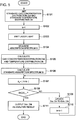
FIG 5 is a flowchart showing steps of a gas analysis method performed by the infrared measurement analysis unit inFIG 4 . -
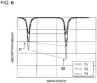
FIG 6 is an example of an absorption spectrum measured by a measurement laser light receiving system. -
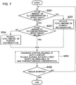
FIG 7 is a flowchart showing steps of a method for controlling a distribution control unit performed by the infrared measurement analysis unit inFIG. 4 . -
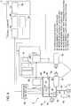
FIG 8 is a schematic diagram of a configuration of a combustion device according to another embodiment of the present embodiment. - Embodiments of the present invention will now be described in detail with reference to the accompanying drawings. It is intended, however, that unless particularly specified, dimensions, materials, shapes, relative positions and the like of components described in the embodiments shall be interpreted as illustrative only and not intended to limit the scope of the present invention.
- For instance, an expression of relative or absolute arrangement such as "in a direction", "along a direction", "parallel", "orthogonal", "centered", "concentric" and "coaxial" shall not be construed as indicating only the arrangement in a strict literal sense, but also includes a state where the arrangement is relatively displaced by a tolerance, or by an angle or a distance whereby it is possible to achieve the same function.
- Further, for instance, an expression of a shape such as a rectangular shape or a cylindrical shape shall not be construed as only the geometrically strict shape, but also includes a shape with unevenness or chamfered corners within the range in which the same effect can be achieved.
- On the other hand, an expression such as "comprise", "include", "have", "contain" and "constitute" are not intended to be exclusive of other components.
- With reference to
FIGs. 1 to 3 , an overall configuration of acombustion facility 1 provided with a gas analysis device according to at least one embodiment of the present invention will be described.FIG 1 is a schematic diagram of acombustion facility 1 provided with a gas analysis device according to at least one embodiment of the present invention.FIG 2 is a schematic diagram for describing each region of the furnace inFIG 1 .FIG. 3 is a cross-sectional view taken along line A-A inFIG 1 . - The
combustion facility 1 includes acombustion furnace 2 for combusting fuel, aflue 4 for guiding combustion air produced in thefurnace 2, are-heating unit 6 for obtaining thermal energy from the combustion air, acombustion controller 8 for controlling a combustion state inside thefurnace 2 by adjusting supply of fuel and air to thefurnace 2, and agas analysis device 10 which analyzes the combustion air (gas) in thefurnace 2. - The
furnace 2 is configured to be surrounded by a wall surface comprising a heat resistant material in a substantially box shape. In thefurnace 2, fuel and air supplied from thecombustion controller 8 described below is combusted, and thereby high-temperature combustion air is produced. Thefurnace 2 has an upper side, in the vertical direction, open, and the open side is connected to theflue 4. The high-temperature combustion air produced in thefurnace 2 forms a flow path so as to be guided into theflue 4. - The
re-heating unit 6 comprises a plurality of re-heaters, and is disposed in the flow path of the combustion air in thefurnace 2 and theflue 4. A re-heater comprises a piping member, and a liquid or a gas is sealed inside the piping member. The liquid or gas sealed inside the re-heater obtains thermal energy through heat exchange with high-temperature combustion air, and thereby turns into steam. The steam travels along a predetermined path from there-heating unit 6, and rotary-drives a non-depicted turbine, thereby converting thermal energy into electrical energy or mechanical energy and outputting the converted energy. - As described above, the
combustion facility 1 functions as a generator or a driving machine. However, the usage of thecombustion facility 1 is not limited to this, and may be a heater for heating a substance with thermal energy obtained by there-heating unit 6. - The
combustion controller 8 controls a combustion state inside thefurnace 2 by adjusting fuel and air supplied to thefurnace 2. Thecombustion controller 8 includes afuel supply unit 12 and anair supply unit 14 for supplying fuel and air, respectively, to thefurnace 2. - The
fuel supply unit 12 includes a powdered-coal burner 16 (hereinafter, referred to as "burner" when needed) for combusting fuel, a powdered-coal supply part 18 for supplying a powdered coal that serves as a fuel, ablower 20 for generating a wind for carrying the fuel, a flow-rate adjustment valve 22 for adjusting the flow rate of the fuel, and apipe 24 connecting the above to one another. - The powdered-
coal supply part 18 is a mechanism configured to supply fuel to thepipe 24. The powdered-coal supplied to thepipe 24 is carried through thepipe 24 by theblower 20, and mixed with air introduced from amain pipe 32 of theair supply unit 14 via the flow-rate adjustment valve 22, before being supplied to theburner 16. Theburner 16 is a combustor disposed so as to have a nozzle exposed inside thefurnace 2. Theburner 16 injects a fuel supplied via thepipe 24 and combusts the fuel inside thefurnace 2. - The
burner 16 is disposed at a plurality of positions inside thefurnace 2, preferably in such a layout that air injected from eachburner 16 forms a swirling air flow inside thefurnace 2. - The powdered-
coal supply part 18 may be a mechanism that produces powdered coal by pulverizing coal and supplies the powdered coal to thepipe 24, or a mechanism that stores a powdered coal produced in advance and supplies the stored powdered coal to thepipe 24. - The
air supply unit 14 includes a primary-air supply unit 26 and a secondary-air supply unit 28 for supplying primary air and secondary air, respectively, to thefurnace 2, ablower 30 which is a blower or a fan for sending air to the primary-air supply unit 26 and the secondary-air supply unit 28 with the above describedfuel supply unit 12, and amain pipe 32 connecting the above to one another. - The primary-
air supply unit 26 includes afirst pipe 36 disposed so that anoutlet 34 is exposed inside thefurnace 2, and a flow-rate adjustment valve 38 configured to adjust the flow rate of air in thefirst pipe 36. Thefirst pipe 36 is connected to themain pipe 32 via the flow-rate adjustment valve 38, and is configured to be capable of introducing air taken into themain pipe 32 by theblower 30 to theoutlet 34. Theoutlet 34 is disposed downstream of theburner 16, in the flow path of the combustion air inside thefurnace 2. The flow-rate adjustment valve 38 is disposed at a connection part between themain pipe 32 and thefirst pipe 36, to adjust the amount of air to be supplied to thefirst pipe 36 from themain pipe 32. - The secondary-
air supply unit 28 includes asecond pipe 42 disposed so that anoutlet 40 is exposed inside thefurnace 2, and a flow-rate adjustment valve 44 configured to be capable of adjusting the flow rate of air in thesecond pipe 42. Thesecond pipe 42 is connected to themain pipe 32 via the flow-rate adjustment valve 44, and is configured to be capable of introducing air taken into themain pipe 32 by theblower 30 to theoutlet 40. Theoutlet 40 is disposed downstream of theoutlet 34, in the flow path of the combustion air inside thefurnace 2. The flow-rate adjustment valve 44 is disposed at a connection part between themain pipe 32 and thesecond pipe 42, and adjusts the amount of air to be supplied to thesecond pipe 42 from themain pipe 32. - The
distribution control unit 46 adjusts the opening degrees of the flow-rate adjustment valves blower 30 to thefuel supply unit 12, the primary-air supply unit 26, and the secondary-air supply unit 28 at a predetermined ratio. In the present embodiment, thedistribution control unit 46 is configured to be controlled automatically on the basis of a control signal from an infrared measurement analysis unit disposed in a control chamber. - With the above configuration, as depicted in
FIG. 2 , formed inside thefurnace 2 are a burner combustion region 48, a non-combusted fuel existence reduction region 50, and a combustion completion region 52, from upstream to downstream. The burner combustion region 48 is a region where the fuel injected from theburner 16 is combusted, extending from theoutlet 34 to the upstream side. The non-combusted fuel existence reduction region 50 is a region where non-reacted fuel and air supplied from theoutlet 34 and theoutlet 40 react, in response to supply of the air from theoutlet 34 and theoutlet 40, which is a region between theoutlet 34 and theoutlet 40, or in other words a region where the secondary air is supplied. The combustion completion region 52 is a region where the remaining fuel and air react, extending from the downstream side of theoutlet 40 to the connection part between thefurnace 2 and theflue 4. - Referring again to
FIG. 1 , thegas analysis device 10 includes ameasurement laser controller 54 for controlling laser light emitted to combustion air in thefurnace 2 for measurement, an infraredmeasurement analysis unit 56 for analyzing a measurement result by receiving the emitted laser light, and controlling thedistribution control unit 46 on the basis of the analysis result, and a two-dimensional measurementresult display part 58 for displaying the analysis result. - A measurement laser
light transmitting system 60 and a measurement laserlight receiving system 62 are disposed on opposite positions inside thefurnace 2, so that laser light emitted from the measurement laserlight transmitting system 60 transmits through the combustion air in thefurnace 2 is received by the measurement laserlight receiving system 62. Particularly in the present embodiment, the measurement laserlight transmitting system 60 and the measurement laserlight receiving system 62 are disposed on a two-dimensional plane substantially along the horizontal direction at the downstream side of theoutlet 40, and thereby the combustion air in the combustion completion region 52 can be analyzed. - The measurement laser
light transmitting system 60 includes a laser diode capable of emitting a laser light which has an infrared wavelength range. The laser diode is a wavelength scanning type laser diode which is capable of adjusting the wavelength of the laser light output by driving electric current, and is capable of wavelength sweep on the basis of a command from themeasurement laser controller 54. The wavelength scanning range of the measurement laserlight transmitting system 60 is selected so as to include the wavelength corresponding to at least two electronic level transitions of the same gas type contained in the combustion air. Particularly in the present embodiment, the laser diode is selected so as to include wavelength corresponding to two electronic level transitions of H2O, which is a type of gas contained in the combustion air. This is because, compared to O2, CO2, and the like also contained in the combustion air, H2O has a wavelength range corresponding to adjacent two electronic level transitions in a relatively close range. - As depicted in
FIG. 3 , a plurality of measurement laserlight transmitting systems 60 and a plurality of measurement laserlight receiving systems 62 are disposed inside thefurnace 2. Thefurnace 2 has a substantially rectangular two-dimensional cross section, as seen from above in the vertical direction. In the present embodiment, the measurement laserlight transmitting systems 60 and the measurement laserlight receiving systems 62 are disposed on opposite sides from each other in the two-dimensional cross section. Provided that n is a natural number equal to or greater than two, n pairs of measurement laserlight transmitting systems 60 and measurement laserlight receiving systems 62 are disposed along each of the vertical direction and the horizontal direction in the drawing so that the measurement paths cross each other at a right angle. In other words, in the present embodiment, in total, 2n pairs of the measurement laserlight transmitting systems 60 and the measurement laserlight receiving systems 62 are provided. Accordingly, the measurement laserlight transmitting systems 60 and the measurement laserlight receiving systems 62 arranged as described above form 2n measurement paths P in total. - The infrared
measurement analysis unit 56 obtains a measurement result by the measurement laserlight receiving system 62, and performs a gas analysis utilizing two-dimensional solution analysis (tomography) on the basis of the measurement result. Next, with reference toFIGs. 4 to 7 , the gas analysis method will be described in detail by each step.FIG. 4 is a block diagram showing a configuration of the infraredmeasurement analysis unit 56.FIG. 5 is a flowchart showing steps of a gas analysis method performed by the infraredmeasurement analysis unit 56 inFIG. 4 .FIG. 6 is an example of an absorption spectrum measured by the measurement laserlight receiving system 62.FIG. 7 is a flowchart showing steps of a method for controlling thedistribution control unit 46 performed by the infraredmeasurement analysis unit 56 inFIG. 4 . - As depicted in
FIG 4 , the infraredmeasurement analysis unit 56 includes ameasurement part 64 for obtaining a measurement result of the measurement laserlight receiving system 62, astandard setting part 66 for setting a standard gas concentration distribution and a standard temperature distribution as a two-dimensional distribution function, and ananalysis part 68 configured to obtain the gas concentration distribution and the temperature distribution by convergence calculation so as to minimize the difference between the absorption amount and the standard absorption. - First, the
standard setting part 66 sets a standard gas concentration distribution Dcr and a standard temperature distribution Dtr on the basis of the measurement result obtained by the measurement part 64 (step S101). The standard gas concentration distribution Dcr and the standard temperature distribution Dtr function as initial values when performing convergence calculation with the gas concentration distribution Dc and the temperature distribution Dt being variables, in the analysis performed by theanalysis part 68. - The standard gas concentration distribution Dcr and the standard temperature distribution Dtr are set on the basis of an absorption amount (absorption spectrum) measured by the measurement laser
light receiving systems 62 from laser light emitted into the combustion air by the measurement laserlight transmitting system 60, the laser light including an absorption wavelength corresponding to at least two electronic level transitions of the same gas type contained in the combustion air.FIG. 6 shows an example of an absorption spectrum measured by the measurement laserlight receiving system 62, the temperature of the combustion air showing three patterns T1, T2, and T3 (T1>T2>T3). In this spectrum, absorption spectra S1 and S2 are present in a wavelength region corresponding to adjacent two electronic level transitions of H2O contained in combustion air. S1 is an absorption spectrum corresponding to the first level transition and S2 is an absorption spectrum corresponding to the second level transition. - The peak rate of the absorption spectra S1 to S2 changes depending on the temperature of the combustion air. Thus, by determining in advance a correlation between the peak ratio of the absorption spectra S1 to S2 and the temperature of combustion air, it is possible to obtain the temperature of combustion air corresponding to the peak ratio of absorption spectra S1 to S2 based on an actual measurement value. The temperature of combustion air obtained as described above corresponds to an average temperature in the measurement path on which the absorption spectrum is measured. The
standard setting part 66 utilizes such temperature dependency of the peak ratio to obtain the average temperature in each measurement path on the basis of the absorption wavelength spectra S1 and S2 measured in the respective measurement paths P. Then, the average temperatures of the respective measurement paths are further averaged, thereby calculating the average temperature of combustion air in thefurnace 2. Then, thestandard setting part 66 sets the standard gas concentration distribution Dcr and the standard temperature distribution Dtr so as to obtain a temperature distribution in which temperatures are constant at the average temperature calculated accordingly over the plane including the plurality of measurement paths P. - Referring again to
FIG. 5 , subsequently, theanalysis part 68 prepares an increment variable k for control when performing the following analysis, and sets the initial value of the variable k to "one" (step S102). Themeasurement laser controller 54 sends a command to the measurement laserlight transmitting systems 60 to emit laser light to combustion air (step S103). Furthermore, the measurement laserlight receiving systems 62 receive laser light from the measurement laserlight transmitting systems 60, and the infraredmeasurement analysis unit 56 obtains an absorption spectrum S in the plurality of measurement paths from the measurement result (step S104). - In the following description, absorption spectra S corresponding to the respective 2n measurement paths P are individually referred to as "S1, S2, ..., S2n".
- The
analysis part 68 estimates the gas concentration distribution Dck and the temperature distribution Dtk, which are two-dimensional distributions, by reconfiguration, on the basis of the absorption spectra S1, S2, S3, ..., S2n corresponding to the plurality of measurement paths (step S105). In the estimation calculation of step S105, theanalysis part 68 determines the gas concentration distribution Dck and the temperature distribution Dtk as functions including common variable parameters. The function is set corresponding to the shape of thefurnace 2 where combustion air to be analyzed exists, on the basis of, for instance, a common cylindrical coordinate system (e.g. the radial directional low-order Fourier series expansion or the Gaussian distribution), further using a two-dimensional distribution function including parameters such as a position of the center axis of the cylindrical coordinate system, an ovalization rate of the coordinate, and a circumferential directional distribution term. - Particularly in the present embodiment, taking into consideration that there is correlation between the gas concentration distribution Dck and the temperature distribution Dtk, the functions representing the gas concentration distribution Dck and the temperature distribution Dtk are set so that the functions share at least the parameters of the position of the center axis of the cylindrical coordinate system and the ovalization rate of the coordinate. Accordingly, an impact of the temperature distribution of combustion air is taken into consideration when calculating the gas concentration distribution, and thereby it is possible to obtain an analysis result that is closer to the actual distribution. Described below is an example of a function derived from the above technical idea.

- In the expression (1), x is the gas concentration distribution Dck, and y is the temperature distribution Dtk, satisifying the following expression.


- In the expression (1), A is the physical-amount center value, B and C are radial distribution coefficients, Dk and Ek are circumferential distribution coefficients, widx and widy are ovalization rates of the coordinate, and xc and yc are center-axis positions of the cylindrical coordinate system.
- In the iterative calculation, the Marquardt method is used, for instance, to update each of the parameters (A, Bi, Ci, Dk, Ek, widx, widy, xc, yc) so as to reduce the difference between the obtained absorption spectrum S and the analytic absorption spectrum Sr.
- Next, a standard absorption spectrum Sr in a plurality of measurement paths is obtained on the basis of the standard gas concentration distribution Dcr and the standard temperature distribution Dtr set in step S101 (S106), and the difference Δk between the standard absorption spectrum Sr and the absorption spectrum S obtained in step S104 is obtained from an expression: Δk=|S-Sr| (Step S107).
- Subsequently, the
analysis part 68 determines whether Δk obtained in step S107 is equal to or greater than Δk-1 (step S108). If Δk is less than Δk-1 (step S108: NO), it means that the difference is reduced compared to the previous control loop, and thus the gas concentration distribution Dck and the temperature distribution Dtk estimated in step S105 are updated as the standard gas concentration distribution Dcr and the standard temperature distribution Dtr (step S109). Then, an increment variable is added (step S110), and the process is returned to step S107. - As a result of repetition of the process of steps S107 to S110, if Δk becomes not less than Δk-1 (step S108: NO), the
analysis part 68 determines that the solution has converged, and outputs the gas concentration distribution Dck and the temperature distribution Dtk estimated in step S205 as analysis results (step S111). As described above, in the present embodiment, when the two-dimensional distribution of the gas concentration is calculated, the gas concentration distribution Dck and the temperature distribution Dtk are treated as variables at the same time, and a solution is sought so as to minimize the difference Δk. - The gas concentration distribution Dck and the temperature distribution Dtk, which are solutions derived as described above, are transmitted to the
distribution control unit 46 and the two-dimensional measurementresult display part 58 as analysis results. Thedistribution control unit 46 adjusts the flow-rate adjustment valves gas analysis device 10, and thereby controls thefuel supply unit 12, the primary-air supply unit 26, and the secondary-air supply unit 28. - Now, with reference to
FIG. 7 , a control example of thedistribution control unit 46 will be described in detail. In this example, the concentration distribution of O2 and CO2 contained in the combustion air as the gas concentration distribution Dck is obtained as an analysis result. - First, the
distribution control unit 46 determines whether the total amount of the O2 concentration in thefurnace 2 is equal to or less than an upper limit target value on the basis of the gas concentration distribution Dck (step S201). If the total amount of the O2 concentration is greater than the upper limit target value (step S201: NO), thedistribution control unit 46 controls theburner 16 and the flow-rate adjustment valves - On the other hand, if the total amount of the O2 concentration is equal to or less than the upper limit target value (step S 201: YES), the
distribution control unit 46 further determines whether the total amount of CO2 concentration is equal to or less than the upper limit target value (step S203). If the total amount of the CO2 concentration is greater than the upper limit target value (step S203: NO), thedistribution control unit 46 controls theburner 16 and the flow-rate adjustment valves - In contrast, if the total amount of the CO2 concentration is equal to or less than than the upper limit value (YES in step S203), the
distribution control unit 46 feedback-controls the balance of theburner 16 and the flow-rate adjustment valves combustion facility 1 is stopped (step S205). If thecombustion facility 1 is in operation (step S205: NO), the process is returned to S201, and the above control is repeated. On the other hand, if thecombustion facility 1 stops (step S205: YES), the series of processes is ended (END). - As described above, the
distribution control unit 46 controls the supply amount of the fuel, the primary air, and the secondary air to thefurnace 2, and thereby achieves an optimum operation in which the temperature unbalance and excess/shortage of oxygen supply in thefurnace 2 are solved, thus improving the power generation efficiency and suppressing an increase in the NOx generation due to excessive O2. Further, the two-dimensionalmeasurement display part 58 visualizes the gas concentration distribution Dck and the temperature distribution Dtk for an operator with a display unit such as a display monitor, which makes it easier to monitor the combustion state in thefurnace 2. -
FIG. 8 is a schematic diagram of a configuration of thecombustion facility 1 according to another embodiment of the present embodiment. In the present embodiment, acontrol panel 70 that can be operated by an operator is provided for a control chamber. Thecontrol panel 70 transmits a control signal corresponding to the content of an input operation to thedistribution control unit 46, and thereby operates thedistribution control unit 46. The control signal transmitted from thecontrol panel 70 to thedistribution control unit 46 is equivalent to the control signal that the infraredmeasurement analysis unit 56 transmits to thedistribution control unit 46 inFIG. 1 , and controls thefuel supply unit 12, the primary-air supply unit 26, and the secondary-air supply unit 28. In other words, in the present embodiment, an operator controls thecontrol panel 70 to manually operate thedistribution control unit 46 and adjust the combustion state. - In the control chamber, a two-dimensional measurement
result display part 58 is disposed, which displays an analysis result by the infraredmeasurement analysis unit 56. The two-dimensional measurementresult display part 58 is, for instance, a unit for visualizing an analysis result for an operator in the control chamber, on a display unit such as a display monitor. - An operator of the
control panel 70 refers to an analysis result displayed on the two-dimensional measurementresult display part 58, which is a display unit such as a display monitor, and thereby determines the combustion state inside thefurnace 2 and operates thecontrol panel 70 in accordance with the determination result. As described above, in the present embodiment, the operator can perform works efficiently while determining the combustion state of thefurnace 2 easily. - As described above, according to the present embodiment, it is possible to provide a gas analysis device for accurately analyzing a gas concentration distribution and a temperature distribution in a system in which combustion gas inside a furnace is not evenly mitigated, a control system and a control assistance system for a combustion, and a gas analysis method.
- The present disclosure can be applied to a gas analysis device for analyzing a gas concentration distribution and a temperature distribution inside a furnace, a control system and a control assistance system for a combustion facility provided with the gas analysis device, and a gas analysis method performed by the gas analysis device.
-
- 1
- Combustion facility
- 2
- Combustion furnace
- 4
- Flue
- 6
- Re-heating unit
- 8
- Combustion controller
- 10
- Gas analysis device
- 12
- Fuel supply unit
- 14
- Air supply unit
- 16
- Powdered-coal burner
- 18
- Powdered-coal supply part
- 20, 30
- Blower
- 22, 38, 44
- Flow-rate adjustment valve
- 24
- Pipe
- 26
- Primary-air supply unit
- 28
- Secondary-air supply unit
- 32
- Main pipe
- 34
- Outlet
- 36
- First pipe
- 42
- Second pipe
- 46
- Distribution control unit
- 48
- Burner combustion region
- 50
- Non-combusted fuel existence reduction region
- 52
- Combustion completion region
- 54
- Measurement laser controller
- 56
- Infrared measurement analysis unit
- 58
- Two-dimensional measurement result display part
- 60
- Measurement laser light transmitting system
- 62
- Measurement laser light receiving system
- 64
- Measurement part
- 66
- Standard setting part
- 68
- Analysis part
- 70
- Control panel
Claims (8)
- A gas analysis device for analyzing a concentration distribution of a combustion gas in a furnace and a temperature distribution inside the furnace, the gas analysis device comprising:a measurement part configured to measure an absorption amount of a laser light including an absorption wavelength corresponding to at least two electronic level transitions having the same component contained in the combustion gas, by emitting the laser light on a plurality of measurement paths disposed so as to pass through the combustion gas;a standard setting part configured to set a standard gas concentration distribution and a standard temperature distribution on the basis of a measurement result of the measurement part; andan analysis part configured to obtain the gas concentration distribution and the temperature distribution by solving a function including the gas concentration distribution and the temperature distribution as variables so as to minimize a difference between the absorption amount measured by the measurement part and a standard absorption amount obtained on the basis of the standard gas concentration distribution and the standard temperature distribution.
- The gas analysis device according to claim 1, wherein the function is set corresponding to a shape of the furnace.
- The gas analysis device according to claim 2, wherein the function is set so as to include at least one of a center axis position, a coordinate ovalization rate, or a circumferential distribution term as a parameter, with respect to a cylindrical coordinate system.
- The gas analysis device according to any one of claims 1 to 3, wherein the standard setting part is configured to set the standard concentration distribution and the standard temperature distribution on the basis of an average temperature of the combustion gas obtained on the basis of a ratio of the absorption amount at wavelengths corresponding to different electronic level transitions included in the laser light in the plurality of measurement paths.
- The gas analysis device according to claim 4, wherein the same component is H2O.
- A control system for a combustion facility, comprising:a fuel supply unit configured to supply fuel to the furnace;an air supply unit configured to supply air to the furnace;the gas analysis device according to any one of claims 1 to 5; anda control unit configured to control a supply amount of the fuel and the air to the furnace by adjusting the fuel supply unit and the air supply unit on the basis of the gas concentration distribution and the temperature distribution analyzed by the gas analysis device.
- A control assistance system for a combustion facility, comprising:a fuel supply unit configured to supply fuel to the furnace;an air supply unit configured to supply air to the furnace;the gas analysis device according to any one of claims 1 to 5; anda display unit configured to display the gas concentration distribution and the temperature distribution analyzed by the gas analysis device.
- A gas analysis method for analyzing a concentration distribution of combustion gas in a furnace and a temperature distribution inside the furnace, the method comprising:a measurement step of measuring an absorption amount of a laser light including an absorption wavelength corresponding to at least two electronic level transitions having the same component contained in the combustion gas, by emitting the laser light on a plurality of measurement paths disposed so as to pass through the combustion gas;a standard setting step of setting a standard gas concentration distribution and a standard temperature distribution on the basis of a measurement result in the measurement step; andan analysis step of obtaining the gas concentration distribution and the temperature distribution by solving a function including the gas concentration distribution and the temperature distribution as variables so as to minimize a difference between the absorption amount measured in the measurement step and a standard absorption amount obtained on the basis of the standard gas concentration distribution and the standard temperature distribution.
Applications Claiming Priority (2)
| Application Number | Priority Date | Filing Date | Title |
|---|---|---|---|
| JP2015066847A JP2016186464A (en) | 2015-03-27 | 2015-03-27 | Gas analyser, combustion facility control system, control support system and gas analysis method |
| PCT/JP2015/083005 WO2016157610A1 (en) | 2015-03-27 | 2015-11-25 | Gas analysis device, control system and control assistance system for combustion equipment, and gas analysis method |
Publications (2)
| Publication Number | Publication Date |
|---|---|
| EP3246694A1 true EP3246694A1 (en) | 2017-11-22 |
| EP3246694A4 EP3246694A4 (en) | 2018-04-25 |
Family
ID=57004100
Family Applications (1)
| Application Number | Title | Priority Date | Filing Date |
|---|---|---|---|
| EP15887752.2A Withdrawn EP3246694A4 (en) | 2015-03-27 | 2015-11-25 | Gas analysis device, control system and control assistance system for combustion equipment, and gas analysis method |
Country Status (5)
| Country | Link |
|---|---|
| US (1) | US20180031233A1 (en) |
| EP (1) | EP3246694A4 (en) |
| JP (1) | JP2016186464A (en) |
| CN (1) | CN107110777A (en) |
| WO (1) | WO2016157610A1 (en) |
Families Citing this family (8)
| Publication number | Priority date | Publication date | Assignee | Title |
|---|---|---|---|---|
| WO2017119283A1 (en) | 2016-01-06 | 2017-07-13 | 国立大学法人徳島大学 | Gas analysis device using laser beam and gas analysis method |
| JP6599307B2 (en) * | 2016-12-28 | 2019-10-30 | 三菱日立パワーシステムズ株式会社 | Combustion device and boiler equipped with the same |
| CN107560754B (en) * | 2017-07-12 | 2019-07-12 | 北京航空航天大学 | A laser beam deflection correction device and method based on modulated sawtooth wave signal |
| CN107688009A (en) * | 2017-11-10 | 2018-02-13 | 华北电力大学 | TDLAS boiler furnace gas two dimension concentration distribution detection method and device based on automatic scanning system |
| CN109324019B (en) * | 2018-12-11 | 2022-04-12 | 北京航空航天大学 | Laser absorption spectrum tomography system for monitoring axisymmetric combustion field |
| KR102118280B1 (en) * | 2019-02-15 | 2020-06-02 | 동아대학교 산학협력단 | Method and apparatus for determining optimized parameters for simultaneously 2 dimensional measurment of temperature and concentration distribution of gas based on tomography |
| CN110514622B (en) * | 2019-08-23 | 2020-07-31 | 北京航空航天大学 | Two-dimensional temperature and concentration reconstruction system and method based on histogram information |
| JP7401768B2 (en) * | 2020-03-26 | 2023-12-20 | 日本製鉄株式会社 | Gas analysis method and gas analysis device |
Family Cites Families (8)
| Publication number | Priority date | Publication date | Assignee | Title |
|---|---|---|---|---|
| JPS62116225A (en) * | 1985-11-15 | 1987-05-27 | Mitsubishi Heavy Ind Ltd | Method for measuring temperature distribution of gas |
| US6389330B1 (en) * | 1997-12-18 | 2002-05-14 | Reuter-Stokes, Inc. | Combustion diagnostics method and system |
| DE19821956A1 (en) * | 1998-05-16 | 1999-11-18 | Deutsch Zentr Luft & Raumfahrt | Method for the quantitative analysis of gas volumes, in particular exhaust gases from combustion devices or systems, and devices for carrying out the method |
| JP2004060910A (en) * | 2002-07-25 | 2004-02-26 | Nippon Soken Inc | Flame combustion control |
| US20110045420A1 (en) * | 2009-08-21 | 2011-02-24 | Alstom Technology Ltd | Burner monitor and control |
| JP5455528B2 (en) * | 2009-09-29 | 2014-03-26 | 三菱重工業株式会社 | Combustion control device |
| US8424292B2 (en) * | 2009-12-31 | 2013-04-23 | General Electric Company | Systems and apparatus relating to the monitoring and/or controlling of selective catalytic reduction processes |
| JP6057430B2 (en) * | 2013-08-21 | 2017-01-11 | 国立大学法人徳島大学 | Gas analysis apparatus and gas analysis method using laser light |
-
2015
- 2015-03-27 JP JP2015066847A patent/JP2016186464A/en active Pending
- 2015-11-25 CN CN201580067967.4A patent/CN107110777A/en active Pending
- 2015-11-25 EP EP15887752.2A patent/EP3246694A4/en not_active Withdrawn
- 2015-11-25 WO PCT/JP2015/083005 patent/WO2016157610A1/en not_active Ceased
- 2015-11-25 US US15/552,670 patent/US20180031233A1/en not_active Abandoned
Also Published As
| Publication number | Publication date |
|---|---|
| JP2016186464A (en) | 2016-10-27 |
| US20180031233A1 (en) | 2018-02-01 |
| EP3246694A4 (en) | 2018-04-25 |
| CN107110777A (en) | 2017-08-29 |
| WO2016157610A1 (en) | 2016-10-06 |
Similar Documents
| Publication | Publication Date | Title |
|---|---|---|
| US20180031233A1 (en) | Gas analysis device, control system and control assistance system for combustion facility, and gas analysis method | |
| Sullivan et al. | Time-averaged characteristics of a reacting fuel jet in vitiated cross-flow | |
| Funke et al. | Experimental and numerical study on optimizing the DLN micromix hydrogen combustion principle for industrial gas turbine applications | |
| García-Armingol et al. | Effect of local flame properties on chemiluminescence-based stoichiometry measurement | |
| Mayrhofer et al. | Evaluation of flamelet-based combustion models for the use in a flameless burner under different operating conditions | |
| Colorado et al. | Emissions and stability performance of a low-swirl burner operated on simulated biogas fuels in a boiler environment | |
| Lammel et al. | High momentum jet flames at elevated pressure: a—experimental and numerical investigation for different fuels | |
| JP5455528B2 (en) | Combustion control device | |
| CN101275748B (en) | Boiler control device and control method | |
| JP2012141862A (en) | Control device for plant and control device for fire power generation plant | |
| Funke et al. | Experimental and numerical study on optimizing the dry low NOx micromix hydrogen combustion principle for industrial gas turbine applications | |
| Peeters et al. | Comparative experimental and numerical investigation of a piloted turbulent natural-gas diffusion flame | |
| JP5277064B2 (en) | Plant control device, thermal power plant control device, and thermal power plant | |
| EP3564583B1 (en) | Combustion device and boiler provided with same | |
| Schultz et al. | Spatially-resolved TDLAS measurements of temperature, H2O column density, and velocity in a direct-connect scramjet combustor | |
| Yang et al. | Effect of blowing ratio and moisture content on tangential effusion cooling performance under reacting flow conditions | |
| JP2017113697A (en) | Reducing agent injection amount sharing control method, denitration method, and denitration system | |
| Reumschüssel et al. | Multi-objective experimental combustor development using surrogate model-based optimization | |
| US20150019181A1 (en) | Estimation of NOx Generation in A Commercial Pulverized Coal Burner using a Dynamic Chemical Reactor Network Model | |
| KR20230109616A (en) | Systems and methods for automated control of industrial processes | |
| Lu¨ ckerath et al. | Experimental investigations of flame stabilization of a gas turbine combustor | |
| JP2008241220A (en) | Boiler control device and control method | |
| Alekseev | Laminar burning velocity of hydrogen and flame structure of related fuels for detailed kinetic model validation | |
| Wetzel et al. | Numerical investigation of lean blow out of a model gas turbine combustion chamber using a presumed JPDF-reaction model by taking heat loss processes into account | |
| Jie et al. | Simultaneous measurement of outlet temperature and species concentrations in a dual-swirl combustor via multi-diagnostic integration |
Legal Events
| Date | Code | Title | Description |
|---|---|---|---|
| PUAI | Public reference made under article 153(3) epc to a published international application that has entered the european phase |
Free format text: ORIGINAL CODE: 0009012 |
|
| 17P | Request for examination filed |
Effective date: 20170627 |
|
| AK | Designated contracting states |
Kind code of ref document: A1 Designated state(s): AL AT BE BG CH CY CZ DE DK EE ES FI FR GB GR HR HU IE IS IT LI LT LU LV MC MK MT NL NO PL PT RO RS SE SI SK SM TR |
|
| AX | Request for extension of the european patent |
Extension state: BA ME |
|
| A4 | Supplementary search report drawn up and despatched |
Effective date: 20180327 |
|
| RIC1 | Information provided on ipc code assigned before grant |
Ipc: F23N 5/00 20060101ALI20180319BHEP Ipc: G01N 21/3554 20140101ALI20180319BHEP Ipc: F23N 5/08 20060101ALI20180319BHEP Ipc: G01N 21/39 20060101AFI20180319BHEP Ipc: F23N 1/02 20060101ALI20180319BHEP Ipc: G01N 21/3504 20140101ALI20180319BHEP Ipc: G01N 21/31 20060101ALI20180319BHEP Ipc: G01K 11/00 20060101ALI20180319BHEP |
|
| DAV | Request for validation of the european patent (deleted) | ||
| DAX | Request for extension of the european patent (deleted) | ||
| STAA | Information on the status of an ep patent application or granted ep patent |
Free format text: STATUS: THE APPLICATION HAS BEEN WITHDRAWN |
|
| 18W | Application withdrawn |
Effective date: 20180712 |