EP3246546A1 - Aircraft engine device - Google Patents
Aircraft engine device Download PDFInfo
- Publication number
- EP3246546A1 EP3246546A1 EP15872131.6A EP15872131A EP3246546A1 EP 3246546 A1 EP3246546 A1 EP 3246546A1 EP 15872131 A EP15872131 A EP 15872131A EP 3246546 A1 EP3246546 A1 EP 3246546A1
- Authority
- EP
- European Patent Office
- Prior art keywords
- fan
- nose cone
- rotating shaft
- casing
- engine apparatus
- Prior art date
- Legal status (The legal status is an assumption and is not a legal conclusion. Google has not performed a legal analysis and makes no representation as to the accuracy of the status listed.)
- Granted
Links
Images


Classifications
-
- F—MECHANICAL ENGINEERING; LIGHTING; HEATING; WEAPONS; BLASTING
- F02—COMBUSTION ENGINES; HOT-GAS OR COMBUSTION-PRODUCT ENGINE PLANTS
- F02C—GAS-TURBINE PLANTS; AIR INTAKES FOR JET-PROPULSION PLANTS; CONTROLLING FUEL SUPPLY IN AIR-BREATHING JET-PROPULSION PLANTS
- F02C7/00—Features, components parts, details or accessories, not provided for in, or of interest apart form groups F02C1/00 - F02C6/00; Air intakes for jet-propulsion plants
- F02C7/04—Air intakes for gas-turbine plants or jet-propulsion plants
-
- B—PERFORMING OPERATIONS; TRANSPORTING
- B64—AIRCRAFT; AVIATION; COSMONAUTICS
- B64C—AEROPLANES; HELICOPTERS
- B64C11/00—Propellers, e.g. of ducted type; Features common to propellers and rotors for rotorcraft
- B64C11/02—Hub construction
-
- B—PERFORMING OPERATIONS; TRANSPORTING
- B64—AIRCRAFT; AVIATION; COSMONAUTICS
- B64D—EQUIPMENT FOR FITTING IN OR TO AIRCRAFT; FLIGHT SUITS; PARACHUTES; ARRANGEMENT OR MOUNTING OF POWER PLANTS OR PROPULSION TRANSMISSIONS IN AIRCRAFT
- B64D33/00—Arrangement in aircraft of power plant parts or auxiliaries not otherwise provided for
- B64D33/02—Arrangement in aircraft of power plant parts or auxiliaries not otherwise provided for of combustion air intakes
-
- F—MECHANICAL ENGINEERING; LIGHTING; HEATING; WEAPONS; BLASTING
- F01—MACHINES OR ENGINES IN GENERAL; ENGINE PLANTS IN GENERAL; STEAM ENGINES
- F01D—NON-POSITIVE DISPLACEMENT MACHINES OR ENGINES, e.g. STEAM TURBINES
- F01D25/00—Component parts, details, or accessories, not provided for in, or of interest apart from, other groups
- F01D25/24—Casings; Casing parts, e.g. diaphragms, casing fastenings
-
- F—MECHANICAL ENGINEERING; LIGHTING; HEATING; WEAPONS; BLASTING
- F02—COMBUSTION ENGINES; HOT-GAS OR COMBUSTION-PRODUCT ENGINE PLANTS
- F02C—GAS-TURBINE PLANTS; AIR INTAKES FOR JET-PROPULSION PLANTS; CONTROLLING FUEL SUPPLY IN AIR-BREATHING JET-PROPULSION PLANTS
- F02C7/00—Features, components parts, details or accessories, not provided for in, or of interest apart form groups F02C1/00 - F02C6/00; Air intakes for jet-propulsion plants
-
- F—MECHANICAL ENGINEERING; LIGHTING; HEATING; WEAPONS; BLASTING
- F02—COMBUSTION ENGINES; HOT-GAS OR COMBUSTION-PRODUCT ENGINE PLANTS
- F02C—GAS-TURBINE PLANTS; AIR INTAKES FOR JET-PROPULSION PLANTS; CONTROLLING FUEL SUPPLY IN AIR-BREATHING JET-PROPULSION PLANTS
- F02C7/00—Features, components parts, details or accessories, not provided for in, or of interest apart form groups F02C1/00 - F02C6/00; Air intakes for jet-propulsion plants
- F02C7/12—Cooling of plants
- F02C7/16—Cooling of plants characterised by cooling medium
- F02C7/18—Cooling of plants characterised by cooling medium the medium being gaseous, e.g. air
-
- F—MECHANICAL ENGINEERING; LIGHTING; HEATING; WEAPONS; BLASTING
- F02—COMBUSTION ENGINES; HOT-GAS OR COMBUSTION-PRODUCT ENGINE PLANTS
- F02C—GAS-TURBINE PLANTS; AIR INTAKES FOR JET-PROPULSION PLANTS; CONTROLLING FUEL SUPPLY IN AIR-BREATHING JET-PROPULSION PLANTS
- F02C7/00—Features, components parts, details or accessories, not provided for in, or of interest apart form groups F02C1/00 - F02C6/00; Air intakes for jet-propulsion plants
- F02C7/32—Arrangement, mounting, or driving, of auxiliaries
-
- F—MECHANICAL ENGINEERING; LIGHTING; HEATING; WEAPONS; BLASTING
- F02—COMBUSTION ENGINES; HOT-GAS OR COMBUSTION-PRODUCT ENGINE PLANTS
- F02C—GAS-TURBINE PLANTS; AIR INTAKES FOR JET-PROPULSION PLANTS; CONTROLLING FUEL SUPPLY IN AIR-BREATHING JET-PROPULSION PLANTS
- F02C7/00—Features, components parts, details or accessories, not provided for in, or of interest apart form groups F02C1/00 - F02C6/00; Air intakes for jet-propulsion plants
- F02C7/36—Power transmission arrangements between the different shafts of the gas turbine plant, or between the gas-turbine plant and the power user
-
- F—MECHANICAL ENGINEERING; LIGHTING; HEATING; WEAPONS; BLASTING
- F02—COMBUSTION ENGINES; HOT-GAS OR COMBUSTION-PRODUCT ENGINE PLANTS
- F02K—JET-PROPULSION PLANTS
- F02K3/00—Plants including a gas turbine driving a compressor or a ducted fan
- F02K3/02—Plants including a gas turbine driving a compressor or a ducted fan in which part of the working fluid by-passes the turbine and combustion chamber
- F02K3/04—Plants including a gas turbine driving a compressor or a ducted fan in which part of the working fluid by-passes the turbine and combustion chamber the plant including ducted fans, i.e. fans with high volume, low pressure outputs, for augmenting the jet thrust, e.g. of double-flow type
- F02K3/06—Plants including a gas turbine driving a compressor or a ducted fan in which part of the working fluid by-passes the turbine and combustion chamber the plant including ducted fans, i.e. fans with high volume, low pressure outputs, for augmenting the jet thrust, e.g. of double-flow type with front fan
-
- B—PERFORMING OPERATIONS; TRANSPORTING
- B64—AIRCRAFT; AVIATION; COSMONAUTICS
- B64D—EQUIPMENT FOR FITTING IN OR TO AIRCRAFT; FLIGHT SUITS; PARACHUTES; ARRANGEMENT OR MOUNTING OF POWER PLANTS OR PROPULSION TRANSMISSIONS IN AIRCRAFT
- B64D33/00—Arrangement in aircraft of power plant parts or auxiliaries not otherwise provided for
- B64D33/02—Arrangement in aircraft of power plant parts or auxiliaries not otherwise provided for of combustion air intakes
- B64D2033/024—Arrangement in aircraft of power plant parts or auxiliaries not otherwise provided for of combustion air intakes comprising cooling means
-
- F—MECHANICAL ENGINEERING; LIGHTING; HEATING; WEAPONS; BLASTING
- F05—INDEXING SCHEMES RELATING TO ENGINES OR PUMPS IN VARIOUS SUBCLASSES OF CLASSES F01-F04
- F05D—INDEXING SCHEME FOR ASPECTS RELATING TO NON-POSITIVE-DISPLACEMENT MACHINES OR ENGINES, GAS-TURBINES OR JET-PROPULSION PLANTS
- F05D2260/00—Function
- F05D2260/20—Heat transfer, e.g. cooling
-
- F—MECHANICAL ENGINEERING; LIGHTING; HEATING; WEAPONS; BLASTING
- F05—INDEXING SCHEMES RELATING TO ENGINES OR PUMPS IN VARIOUS SUBCLASSES OF CLASSES F01-F04
- F05D—INDEXING SCHEME FOR ASPECTS RELATING TO NON-POSITIVE-DISPLACEMENT MACHINES OR ENGINES, GAS-TURBINES OR JET-PROPULSION PLANTS
- F05D2260/00—Function
- F05D2260/40—Transmission of power
- F05D2260/403—Transmission of power through the shape of the drive components
- F05D2260/4031—Transmission of power through the shape of the drive components as in toothed gearing
- F05D2260/40311—Transmission of power through the shape of the drive components as in toothed gearing of the epicyclical, planetary or differential type
-
- Y—GENERAL TAGGING OF NEW TECHNOLOGICAL DEVELOPMENTS; GENERAL TAGGING OF CROSS-SECTIONAL TECHNOLOGIES SPANNING OVER SEVERAL SECTIONS OF THE IPC; TECHNICAL SUBJECTS COVERED BY FORMER USPC CROSS-REFERENCE ART COLLECTIONS [XRACs] AND DIGESTS
- Y02—TECHNOLOGIES OR APPLICATIONS FOR MITIGATION OR ADAPTATION AGAINST CLIMATE CHANGE
- Y02T—CLIMATE CHANGE MITIGATION TECHNOLOGIES RELATED TO TRANSPORTATION
- Y02T50/00—Aeronautics or air transport
- Y02T50/60—Efficient propulsion technologies, e.g. for aircraft
Definitions
- the present invention relates to an aircraft engine apparatus.
- Patent Literature 1 discloses a configuration in which, at the upstream side of the fan, flow-rectifying guide blades (stationary blades) extend between the nose cone and the fan case. In this configuration, the radially inner ends of the guide blades are fixed to the nose cone, and the radially outer ends of the guide blades are fixed to the fan case. Therefore, the nose cone stays stationary even while the fan is rotating.
- an object of the present invention is to, in an aircraft engine, reduce the burden of designing and suppress an increase in the weight while allowing the nose cone to be kept stationary.
- An aircraft engine apparatus includes: a rotating shaft; a fan driven by the rotating shaft; a fan case surrounding the fan from outside in a radial direction of the rotating shaft; a nose cone disposed upstream of the fan; a casing that accommodates at least part of the rotating shaft and supports the fan case; a first motive force transmitter that transmits motive force of the rotating shaft to the fan; and a support member disposed inward of the first motive force transmitter in the radial direction, the support member coupling the nose cone to the casing such that the support member supports the nose cone in a stationary state.
- the support member which supports the nose cone in a stationary state, is disposed radially inward of the first motive force transmitter. Therefore, unlike conventional guide blades, it is not necessary to carefully design the shape of the support member from the viewpoint of fluid dynamics so that the support member will not hinder the flow of air flowing into the fan. In addition, since the support member is disposed radially inward of the first motive force transmitter, an increase in the size of the support member in the radial direction can be suppressed, and thereby an increase in the weight can be suppressed.
- the present invention makes it possible to, in an aircraft engine apparatus, reduce the burden of designing and suppress an increase in the weight while allowing the nose cone to be kept stationary.
- upstream refers to upstream in the direction of air flowing inside an engine unless otherwise specified.
- downstream refers to downstream in the direction of air flowing inside the engine unless otherwise specified. That is, the term “upstream side” refers to the side at which a fan is provided in the axial direction of a rotating shaft of the engine, and the “downstream side” refers to the side at which a tail cone is provided in the axial direction of the rotating shaft of the engine.
- radial direction or “radially” refers to the radial direction with reference to the axial direction of the rotating shaft of the engine unless otherwise specified.
- circumferential direction or “circumferentially” refers to the circumferential direction with reference to the axial direction of the rotating shaft of the engine unless otherwise specified.
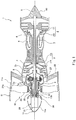
- Fig. 1 is a sectional view showing an aircraft engine apparatus 1 (which may be hereinafter referred to as an "engine apparatus 1") according to Embodiment 1.
- Fig. 2 is an enlarged sectional view of a fan 10 and its vicinity of the aircraft engine apparatus 1.
- the engine apparatus 1 is a biaxial gas turbine engine of a GTF (Geared Turbo Fan) type, and includes a casing 2, a compressor 3, a turbine 4, a combustor 5, a low-pressure shaft 6, a high-pressure shaft 7, a transmission 8, a coupling member 9, the fan 10, a fan case 11, a torque tube 12, a nose cone 13, and a power generator 28. That is, the engine apparatus 1 includes an engine and aircraft equipment (a power generator).
- the casing 2 is a cylindrical casing, and extends in the longitudinal direction of the engine apparatus 1.
- the casing 2 accommodates at least part of the low-pressure shaft 6, and supports the fan case 11.
- the casing 2 accommodates the compressor 3, the turbine 4, the combustor 5, the low-pressure shaft 6, the high-pressure shaft 7, the transmission 8, and the coupling member 9.
- the compressor 3 is disposed at the upstream side inside the casing 2.
- the turbine 4 is disposed at the downstream side inside the casing 2.
- the combustor 5 is disposed between the compressor 3 and the turbine 4.
- the compressor 3 includes an upstream-side low-pressure compressor 14 and a downstream-side high-pressure compressor 15.
- the turbine 4 includes an upstream-side high-pressure turbine 16 and a downstream-side low-pressure turbine 17. Each of the high-pressure turbine 16 and the low-pressure turbine 17 is driven to rotate when the engine apparatus 1 is driven.
- the low-pressure shaft 6 (rotating shaft) extends in the longitudinal direction of the engine apparatus 1, and is pivotally supported around an axis X of the engine apparatus 1.
- the low-pressure compressor 14 and the low-pressure turbine 17 are coupled to the low-pressure shaft 6.
- the high-pressure shaft 7 (rotating shaft) is pivotally supported around the axis X in a state where the low-pressure shaft 6 is inserted in the high-pressure shaft 7.
- the high-pressure compressor 15 and the high-pressure turbine 16 are coupled to the high-pressure shaft 7.
- the combustor 5 is provided between the casing 2 and the high-pressure shaft 7 inside the casing 2.
- the inner space of the casing 2 is open to the outside on both sides in its longitudinal direction. Through a passage 2a formed at the upstream side in the engine apparatus 1, outside air is introduced toward the downstream side. A tail cone 40 is provided at the downstream side of the casing 2.
- the fan case 11 is a cylindrical case whose diameter is greater than that of the casing 2, and is disposed at the upstream side of the casing 2. The fan 10 is accommodated in the inner space of the fan case 11, and the fan case 11 surrounds the fan 10. The driving force of the low-pressure shaft 6 is transmitted to the fan 10.
- the thrust force of the engine apparatus 1 is obtained from: a jet stream of combustion gas jetted out from the combustor 5 to the downstream side passing around the tail cone 40; and a high-speed air stream jetted out from the fan 10 to the downstream side passing around the casing 2.
- the transmission 8 is provided between the low-pressure shaft 6 and the coupling member 9, and is disposed downstream of the fan 10 and upstream of the compressor 3.
- the transmission 8 includes: a sun gear 19; a plurality of planetary gears 20 arranged at intervals around the sun gear 19 and meshed with the sun gear 19; a ring gear 21 provided in a manner to surround the outer periphery of each planetary gear 20 and including internal teeth meshed with the planetary gears 20; and a carrier 22 pivotally supporting the planetary gears 20.
- the transmission 8 herein is a star-type planetary gear mechanism, in which the planetary gears 20 do not revolve.
- the carrier 22 is coupled to the casing 2, and is fixed at a predetermined position between the sun gear 19 and the ring gear 21.
- the carrier 22 is configured as an unmovable (stationary) part fixed at the predetermined position.
- Each of the planetary gears 20 is positioned at a predetermined position in the circumferential direction of the sun gear 19 by the carrier 22, which is the unmovable part of the transmission 8, and is pivotally supported at the predetermined position by the carrier 22.
- An insertion hole 19a is formed in the central portion of the sun gear 19.
- the sun gear 19 is coupled to the low-pressure shaft 6 in a state where one end portion 6a of the low-pressure shaft 6 is inserted in the insertion hole 19a.
- the carrier 22 includes at least one extended portion 22a, which extends in the radial direction toward an inner peripheral surface 2b of the casing 2.
- a support structure 23 coupled to the casing 2 is provided inside the casing 2.
- the support structure 23 includes a body portion 23a and a plurality of supporting arms 23b extending from the body portion 23a.
- the body portion 23a has a cylindrical shape, and accommodates the transmission 8 therein.
- Each of the supporting arms 23b extends radially inward from the inner peripheral surface 2b of the casing 2, and is connected to the body portion 23a.
- the extended portion 22a of the carrier 22 is coupled to the body portion 23a.
- the carrier 22 is coupled to the casing 2 via the support structure 23.
- the transmission 8 is used as a FDGS (Fan Drive Gear System) that reduces the rotational speed of the fan 10 to be lower than the rotational speed of the low-pressure shaft 6.
- the transmission 8 reduces and transmits part of the rotational driving force of the low-pressure shaft 6 to the fan 10.
- the coupling member 9, which is a cylindrical hollow member extending in the direction of the axis X, is coupled to the ring gear 21 of the transmission 8, and the coupling member 9 is also coupled to the fan 10.
- the coupling member 9 is used as a first motive force transmitter, which is coupled to the low-pressure shaft 6 and the fan 10 and which transmits part of the driving force of the low-pressure shaft 6 to the fan 10.
- the coupling member 9 is coupled to the low-pressure shaft 6 via the transmission 8.
- the coupling member 9 includes: a tubular body portion 9a extending in the direction of the axis X of the low-pressure shaft 6; and an expanded diameter portion 9b provided on one end of the body portion 9a, the one end being adjacent to the transmission 8.
- the expanded diameter portion 9b is coupled to the ring gear 21 while covering part of the outer periphery of the ring gear 21.
- a bearing B1 is provided between the support structure 23 and the outer peripheral surface of the body portion 9a of the coupling member 9. Accordingly, the coupling member 9 is supported by the support structure 23, such that the coupling member 9 is rotatable around the axis X.
- the fan 10 includes: a fan hub 25; and a plurality of fan blades 24, which are coupled to the fan hub 25 such that they are arranged at intervals in the circumferential direction and extend in a radial manner.
- a distal end portion 24a of each of the fan blades 24 is covered by the annular fan case 11.
- the fan case 11 is supported by the casing 2 via a plurality of fixing vanes 26.
- An outer peripheral surface 11a of the fan case 11 is supported by a nacelle (not shown) extending in the longitudinal direction of the engine apparatus 1. Part of outside air fed from the fan 10 passes through an air passage formed between the casing 2 and the nacelle from the upstream side toward the downstream side of the engine apparatus 1.
- the fan hub 25 includes a cylindrical base portion 25a and a plurality of joint portions 25b provided around the base portion 25a.
- the fan hub 25 is coupled to a groove 9c formed in the peripheral surface of the body portion 9a by spline coupling in a state where the body portion 9a of the coupling member 9 is inserted in the base portion 25a. Accordingly, the fan 10 is coupled to the coupling member 9 and driven by the low-pressure shaft 6.
- a proximal end portion 24b of each of the fan blades 24 is coupled to a corresponding one of the joint portions 25b. It should be noted that the fan blades 24 and the fan hub 25 may be integrally formed.
- a downstream end portion of the nose cone 13 is fitted to one end portion of the coupling member 9 via a bearing B2, the one end portion being adjacent to the fan 10.
- the nose cone 13 includes: a cone portion 13a having a conoid shape, which is positioned upstream of the fan 10 at the center in the radial direction and whose diameter is reduced forward; and a base portion 13b fixed to the downstream end portion of the cone portion 13a.
- the base portion 13b is, for example, a sleeve-like portion.
- the base portion 13b of the nose cone 13 is fitted to one end portion of the coupling member 9 via the bearing B2.
- the nose cone 13 is supported by the coupling member 9 via the bearing B2, such that the nose cone 13 is rotatable relative to the coupling member 9. In this manner, the nose cone 13 is positioned and supported by the coupling member 9 in the radial direction.
- the nose cone 13 Upstream of the fan 10, the nose cone 13 is mechanically spaced apart from the fan case 11. That is, radially outward of the nose cone 13 and upstream of the fan 10, the nose cone 13 is not connected to the fan case 11. Thus, upstream of the fan 10, there is no guide blade coupling the nose cone 13 and the fan case 11. Accordingly, between the outer peripheral surface of the nose cone 13 and the inner peripheral surface of the fan case 11, an annular space is continuously formed around the nose cone 13 from the upstream end of the nose cone 13 to the upstream end of the fan 10 in the direction of the axis X.
- the torque tube 12 Radially inward of the coupling member 9 and radially outward of a drive shaft 32, the torque tube 12, which is a hollow support member supporting the nose cone 13, is disposed.
- the torque tube 12 extends in the direction of the axis X inside the body portion 9a of the coupling member 9.
- One end portion 12a of the torque tube 12 is coupled to the base portion 13b of the nose cone 13, and the other end portion 12b of the torque tube 12 is coupled to the carrier 22, which is the unmovable part of the transmission 8. In this manner, the torque tube 12 is coupled to the casing 2 via the carrier 22, and positions and restricts the nose cone 13 in the rotation direction.
- the torque tube 12 couples the nose cone 13 to the casing 2, such that the torque tube 12 supports the nose cone 13 in a stationary state when the fan 10 rotates.
- the torque tube 12 herein is configured to be coupled to the base portion 13b of the nose cone 13, the manner of coupling the torque tube 12 is not thus limited, so long as the torque tube 12 is coupled to the nose cone 13.
- the torque tube 12 may be coupled to the cone portion 13a.
- the power generator 28 is accommodated in the inner space of the nose cone 13.
- the power generator 28 is one example of aircraft equipment provided in the nose cone 13.
- the power generator 28 is fixed to the base portion 13b of the nose cone 13. Accordingly, the torque tube 12 positions and restricts not only the nose cone 13 but also the power generator 28 in both the radial direction and the rotation direction.
- the drive shaft 32 which transmits the driving force of the low-pressure shaft 6 to a generator input shaft 30 of the power generator 28, is provided radially inward of the coupling member 9 (the first motive force transmitter).
- the drive shaft 32 is used as a second motive force transmitter, which transmits part of the driving force of the low-pressure shaft 6 to the power generator 28.
- the generator input shaft 30 of the power generator 28 passes through an opening 13ba of the base portion 13b of the nose cone 13, and protrudes toward the drive shaft 32.
- One end portion 32a of the drive shaft 32 is coupled to the generator input shaft 30 of the power generator 28 by spline coupling, and the other end portion 32b of the drive shaft 32 is inserted in the one end portion 6a of the low-pressure shaft 6 and coupled thereto by spline coupling.
- the one end portion 6a of the low-pressure shaft 6 is inserted in the sun gear 19 of the transmission 8 and coupled thereto. Part of the driving force of the low-pressure shaft 6 is transmitted to the generator input shaft 30 via the drive shaft 32, and the power generator 28 generates electric power by being driven at the same rotational speed as the rotational speed of the low-pressure shaft 6.
- the torque tube 12 In the radial direction, the torque tube 12 is disposed in a gap between the coupling member 9 and the drive shaft 32.
- a motive force transmitting path extending from the low-pressure shaft 6 to the fan 10, the torque tube 12 supporting the nose cone 13 and the power generator 28, and a motive force transmitting path extending from the low-pressure shaft 6 to the power generator 28 are arranged in this order from the outer side to the inner side in the radial direction.
- Electric power generated by the power generator 28 is supplied to external equipment via a terminal 31.
- Wiring connected to the terminal 31 of the power generator 28 is, for example, extended along the outer periphery of the torque tube 12 through an insertion hole (not shown) formed in the base portion 13b of the nose cone 13.
- the wiring is further extended along the support structure 23 and the fixing vanes 26, and thereby taken out of the engine apparatus 1. In this manner, the wiring can be installed so that the wiring will not hinder the rotation of the ring gear 21, the coupling member 9, and the fan 10 and the rotation of the generator input shaft 30 and the drive shaft 32.
- the torque tube 12 which supports the nose cone 13 in a stationary state, is disposed radially inward of the coupling member 9. Therefore, unlike conventional guide blades, it is not necessary to carefully design the shape of the torque tube 12 from the viewpoint of fluid dynamics so that the torque tube 12 will not hinder the flow of air flowing into the fan 10.
- the torque tube 12 is disposed radially inward of the coupling member 9, an increase in the size of the torque tube 12 in the radial direction can be suppressed, and thereby an increase in the weight can be suppressed. This makes it possible to, in the aircraft engine apparatus 1, reduce the burden of designing and suppress an increase in the weight while allowing the nose cone 13 to be kept stationary.
- the nose cone 13 Since the nose cone 13 is kept stationary while the fan 10 is rotating, a line of air flow that is guided by the nose cone 13 toward the fan blades 24 is prevented from becoming curved and unstable due to the rotational external force of the nose cone 13. As a result, the air flow around the nose cone 13 is stabilized, and a transition point where a laminar flow changes into a turbulent flow can be shifted to the downstream side. Consequently, the thickness of a turbulent boundary layer at the inlet of the fan blades 24 can be made thin, and a region where the fan efficiency is lowered due to the turbulent flow can be reduced.
- the nose cone 13 is a non-rotating body, it is not necessary, for example, to make the shape of the nose cone 13 axisymmetric, and the degree of freedom in terms of the shape of the nose cone 13 is increased. Furthermore, since the nose cone 13 is a non-rotating body, centrifugal force and so forth exerted on the nose cone 13 are eliminated. As a result, the rigidity that the nose cone 13 is required to have is reduced, which makes it possible to reduce the weight of the nose cone 13.
- the power generator 28 is exemplified as the aircraft equipment accommodated in the nose cone 13.
- the aircraft equipment accommodated in the nose cone 13 is not limited to the power generator 28, but may be any other aircraft equipment that is driven by the drive shaft 32 to operate (e.g., a pump).
- Fig. 3 is an enlarged sectional view of the fan 10 and its vicinity of an aircraft engine 100 according to Embodiment 2.
- a transmission 108 provided in the engine 100 includes: an input gear 87, a plurality of (five as one example) two-stage gears 88, and an output gear 89.
- the transmission 108 is accommodated in a cylindrical body portion 123a of a support structure 123.
- the input gear 87 is provided on the one end portion 6a of the low-pressure shaft 6, and transmits the rotational driving force of the low-pressure shaft 6 to each of the two-stage gears 88.
- Each of the plurality of two-stage gears 88 includes a first gear 88A and a second gear 88B.
- the first gear 88A is meshed with the input gear 87.
- the second gear 88B is meshed with the output gear 89.
- the number of teeth of the first gear 88A is different from that of the second gear 88B. As one example, the number of teeth of the first gear 88A is set to be larger than the number of teeth of the second gear 88B.
- the two-stage gears 88 are arranged to be spaced apart from one another in the circumferential direction of the low-pressure shaft 6 in a state where a rotational axis Y of each two-stage gear 88 is parallel to the axial direction of the generator input shaft 30.
- Each of the two-stage gears 88 is pivotally supported by a carrier 123c, which is provided inside the body portion 123a of the support structure 123.
- the output gear 89 is provided integrally with a coupling member 109 and positioned on the other end side of the coupling member 109.
- the output gear 89 transmits the rotational driving force of each of the two-stage gears 88 to the fan 10 via the coupling member 109.
- part of the rotational driving force of the low-pressure shaft 6 is transmitted to the fan 10 via the input gear 87, the two-stage gears 88, the output gear 89, and the coupling member 109 sequentially.
- the transmission 108 includes a space S, through which a torque tube 112 passes from the upstream side to the downstream side.
- the torque tube 112 extends from the inner space of the cylindrical coupling member 109, which extends in the direction of the axis X, to the downstream side of the input gear 87 through gaps between adjacent two-stage gears 88 (i.e., through the space S).
- one end portion 112a of the torque tube 112 is coupled to the nose cone 13
- the other end portion 112b of the torque tube 112 is coupled to the body portion 123a of the support structure 123.
- the support structure 123 is supported by the inner peripheral surface 2b of the casing 2 via supporting arms 123b.
- the nose cone 13 is coupled to the casing 2 via the torque tube 112 and the support structure 123.
- the torque tube 12 and the support structure 123 couple the casing 2 and the nose cone 13 together, and are used as support members supporting the nose cone 13.
- Fig. 4 is an enlarged sectional view of the fan 10 and its vicinity of an aircraft engine 200 according to Embodiment 3.
- a nose cone 213 includes: a cone portion 213a having a conoid shape, which is positioned upstream of the fan 10 at the center in the radial direction and whose diameter is reduced forward; and a base portion 213b fixed to the downstream end portion of the cone portion 213a.
- the cone portion 213a is, at least partly, formed as a transparent portion.
- the cone portion 213a includes: a non-transparent cone body portion 213aa, the upstream end of which is provided with a window opening H and which is in the shape of a circular truncated cone; and a conoid and transparent sealing portion 213ab, which is fixed to the cone body portion 213a in a manner to seal the window opening H.
- the base portion 213b is a plate-shaped member that seals an opening formed at the downstream end of the cone portion 213a, and is spaced apart from the coupling member 9. That is, radially outward of the torque tube 12 and upstream of the fan 10, the nose cone 213 is mechanically spaced apart from the coupling member 9.
- the base portion 213b of the nose cone 213 is fixed to the torque tube 12 coupled to the carrier 22 of the transmission 8. With this configuration, the nose cone 213 is supported such that the nose cone 213 is kept stationary even while the fan 10 is rotating.
- a camera 228 is provided in the nose cone 213.
- the camera 228 is aircraft equipment that optically accesses the outside of the nose cone 213. Specifically, the camera 228 is accommodated in the nose cone 213 so that an image of the view in front of the engine apparatus 200 can be taken through the transparent sealing portion 213ab.
- the camera 228 is fixed to the base portion 213b of the nose cone 213, and wiring (not shown) of the camera 228 is extended to the outside of the nose cone 213 through an opening 213ba of the base portion 213b. Since the camera 228 is equipment that does not need mechanical driving force, no drive shaft is disposed in the inner space of the torque tube 12.
- the aircraft equipment accommodated in the nose cone 213 is not limited to the camera 228, but may be any other aircraft equipment that accesses the outside of the nose cone 213 by radio waves, by sound waves, or optically (e.g., a radar).
- the aircraft equipment accommodated in the nose cone is capable of accessing the outside of the nose cone through the nose cone even if the nose cone is not provided with a transparent portion (e.g., in a case where the aircraft equipment is radio wave utilizing equipment)
- the entire nose cone may be made non-transparent.
- Fig. 5 is an enlarged sectional view of the fan 10 and its vicinity of an aircraft engine 300 according to Embodiment 4.
- the nose cone 13 is provided with a heat exchanger 334 as aircraft equipment.
- the heat exchange 334 is an oil cooler.
- a predetermined cooling fluid e.g., part of oil flowing inside a housing 329 is circulated inside the housing 329 so that the cooling fluid can exchange heat with, and thereby cool down, heat-generating components in the housing 329.
- piping 332 for discharging the cooling fluid that has been used to exchange heat with the heat generating components in the housing 329 to the outside; and piping 333 for introducing the cooling fluid that has been cooled down into the power generator 328.
- the piping 332 and the piping 333 are inserted in an insertion hole 13c and an insertion hole 13d, respectively, which are formed in the nose cone 13.
- the piping 332 and the piping 333 are coupled to the heat exchanger 334 mounted along the outer surface of the nose cone 13.
- the heat exchanger 334 is of a surface type and includes a body 335 and a plurality of radiation fins 336.
- the body 335 is a thin box-type casing, and includes a plate (not shown) therein, on which corrugated fins are formed.
- the corrugated fins form a plurality of channels, which are configured such that the cooling fluid is allowed to flow through the channels.
- the plurality of radiation fins 336 are thermal-coupled to the body 335 in a state where the fins 336 are provided upright on the outer surface of the body 335.
- the cooling fluid that has been used to cool down the power generator 328 is fed to the body 335 of the heat exchanger 334 through the piping 332. While the engine is being driven, a large amount of outside air comes into contact with the radiation fins 336 of the heat exchanger 334. This allows the cooling fluid flowing inside the body 335 to exchange heat well with the outside air, and as a result, the cooling fluid is cooled down.
- the cooling fluid also exchanges heat with the nose cone 13 via the body 335, and is thereby cooled down. Accordingly, the cooling fluid that has been sufficiently cooled down can be returned into the housing 429 through the piping 333, and reused for the heat exchange with each component in the housing 329.
- the power generator 328 when the power generator 328 performs electric power generation, the power generator 328 can be favorably cooled down by the cooling fluid. Therefore, improvement in power generation efficiency can be expected. Moreover, since the nose cone 13 is provided with the heat exchanger 334, the piping 332 and 333 of the cooling fluid for cooling down the power generator 328 can be shortened. This makes it possible to suppress weight increase due to the installation of the heat exchanger 334 and the piping 332 and 333 to some extent. It should be noted that the heat exchanger is not limited to the surface type that is in surface contact with the nose cone, but may be of a different type. For example, although the heat exchanger 334 in the present embodiment has a conoid shape and is provided along the cone portion 13a of the nose cone 13, the heat exchanger 334 may have a different shape.
- aircraft equipment is accommodated in the nose cone.
- no aircraft equipment may be accommodated in the nose cone.
- the drive shaft 32 may be eliminated.
- Each of the above-described embodiments illustratively shows a configuration in which the coupling member and the low-pressure shaft are coupled via the transmission.
- the transmission is not an essential component.
- the coupling member and the low-pressure shaft may be coupled via a motive force transmitting mechanism that includes a space through which the support member passes.
- Examples of such an adoptable motive force transmitting mechanism include: a mechanism in which the number of gears is modified such that the input gear 87, the plurality of two-stage gears 88, and the output gear 89, which are shown in Fig. 3 , transmit the motive force at a constant speed; and a mechanism in which the motive force is transmitted at a constant speed by means of a belt.
- the torque tube may be indirectly coupled to the casing via the transmission by coupling the torque tube to the transmission that is coupled to the casing, or alternatively, the torque tube may be directly coupled to the casing without via the transmission.
- the torque tube may pivotally support the drive shaft 32 via a bearing.
- the coupling member 9 or 109 may be pivotally supported by a different bearing, for example, one provided on the outer periphery of the torque tube 12 or 112.
- the transmission in each of the above-described embodiments may be configured by using a continuously variable transmission.
- the continuously variable transmission may be a belt-driven continuously variable transmission including a plurality of pulleys and a belt that transmits motive force between the plurality of pulleys.
- the torque tube may be provided such that the torque tube passes through a space formed between the plurality of pulleys.
Landscapes
- Engineering & Computer Science (AREA)
- Chemical & Material Sciences (AREA)
- Combustion & Propulsion (AREA)
- Mechanical Engineering (AREA)
- General Engineering & Computer Science (AREA)
- Aviation & Aerospace Engineering (AREA)
- Structures Of Non-Positive Displacement Pumps (AREA)
Abstract
Description
- The present invention relates to an aircraft engine apparatus.
- In an aircraft turbine engine, at the center in its radial direction, a nose cone that has a conoid shape and whose diameter is reduced forward is provided upstream of a fan. Usually, the nose cone is fixed to the hub of the fan and rotates integrally with the fan. Meanwhile,
Patent Literature 1 discloses a configuration in which, at the upstream side of the fan, flow-rectifying guide blades (stationary blades) extend between the nose cone and the fan case. In this configuration, the radially inner ends of the guide blades are fixed to the nose cone, and the radially outer ends of the guide blades are fixed to the fan case. Therefore, the nose cone stays stationary even while the fan is rotating. - PTL 1: Japanese Laid-Open Patent Application Publication No.
2013-199936 - However, in the case of adopting the guide blades disclosed in
Patent Literature 1 in an attempt to keep the nose cone stationary while the fan is rotating, it is necessary to carefully design the shape of the guide blades from the viewpoint of fluid dynamics so that the guide blades will not hinder the flow of air flowing into the fan. Moreover, since the guide blades extend radially outward from the nose cone and are connected to the fan case, the size of the guide blades in the radial direction is great, which causes an increase in the overall weight of the engine. - In view of the above, an object of the present invention is to, in an aircraft engine, reduce the burden of designing and suppress an increase in the weight while allowing the nose cone to be kept stationary.
- An aircraft engine apparatus according to one aspect of the present invention includes: a rotating shaft; a fan driven by the rotating shaft; a fan case surrounding the fan from outside in a radial direction of the rotating shaft; a nose cone disposed upstream of the fan; a casing that accommodates at least part of the rotating shaft and supports the fan case; a first motive force transmitter that transmits motive force of the rotating shaft to the fan; and a support member disposed inward of the first motive force transmitter in the radial direction, the support member coupling the nose cone to the casing such that the support member supports the nose cone in a stationary state.
- According to the above configuration, the support member, which supports the nose cone in a stationary state, is disposed radially inward of the first motive force transmitter. Therefore, unlike conventional guide blades, it is not necessary to carefully design the shape of the support member from the viewpoint of fluid dynamics so that the support member will not hinder the flow of air flowing into the fan. In addition, since the support member is disposed radially inward of the first motive force transmitter, an increase in the size of the support member in the radial direction can be suppressed, and thereby an increase in the weight can be suppressed.
- The present invention makes it possible to, in an aircraft engine apparatus, reduce the burden of designing and suppress an increase in the weight while allowing the nose cone to be kept stationary.
-
-
Fig. 1 is a sectional view showing an aircraft engine apparatus according to Embodiment 1. -
Fig. 2 is an enlarged sectional view of a fan and its vicinity of the aircraft engine apparatus according to Embodiment 1. -
Fig. 3 is an enlarged sectional view of a fan and its vicinity of an aircraft engine apparatus according to Embodiment 2. -
Fig. 4 is an enlarged sectional view of a fan and its vicinity of an aircraft engine apparatus according to Embodiment 3. -
Fig. 5 is an enlarged sectional view of a fan and its vicinity of an aircraft engine apparatus according to Embodiment 4. - Hereinafter, embodiments of the present invention are described with reference to the drawings. It should be noted that, in the description below, the term "upstream" refers to upstream in the direction of air flowing inside an engine unless otherwise specified. Similarly, the term "downstream" refers to downstream in the direction of air flowing inside the engine unless otherwise specified. That is, the term "upstream side" refers to the side at which a fan is provided in the axial direction of a rotating shaft of the engine, and the "downstream side" refers to the side at which a tail cone is provided in the axial direction of the rotating shaft of the engine. The term "radial direction" or "radially" refers to the radial direction with reference to the axial direction of the rotating shaft of the engine unless otherwise specified. Similarly, the term "circumferential direction" or "circumferentially" refers to the circumferential direction with reference to the axial direction of the rotating shaft of the engine unless otherwise specified.
-
Fig. 1 is a sectional view showing an aircraft engine apparatus 1 (which may be hereinafter referred to as an "engine apparatus 1") according toEmbodiment 1.Fig. 2 is an enlarged sectional view of afan 10 and its vicinity of theaircraft engine apparatus 1. As shown inFig. 1 andFig. 2 , as one example, theengine apparatus 1 is a biaxial gas turbine engine of a GTF (Geared Turbo Fan) type, and includes acasing 2, acompressor 3, aturbine 4, acombustor 5, a low-pressure shaft 6, a high-pressure shaft 7, atransmission 8, acoupling member 9, thefan 10, afan case 11, atorque tube 12, anose cone 13, and apower generator 28. That is, theengine apparatus 1 includes an engine and aircraft equipment (a power generator). - The
casing 2 is a cylindrical casing, and extends in the longitudinal direction of theengine apparatus 1. Thecasing 2 accommodates at least part of the low-pressure shaft 6, and supports thefan case 11. Specifically, thecasing 2 accommodates thecompressor 3, theturbine 4, thecombustor 5, the low-pressure shaft 6, the high-pressure shaft 7, thetransmission 8, and thecoupling member 9. Thecompressor 3 is disposed at the upstream side inside thecasing 2. Theturbine 4 is disposed at the downstream side inside thecasing 2. Thecombustor 5 is disposed between thecompressor 3 and theturbine 4. Thecompressor 3 includes an upstream-side low-pressure compressor 14 and a downstream-side high-pressure compressor 15. - The
turbine 4 includes an upstream-side high-pressure turbine 16 and a downstream-side low-pressure turbine 17. Each of the high-pressure turbine 16 and the low-pressure turbine 17 is driven to rotate when theengine apparatus 1 is driven. The low-pressure shaft 6 (rotating shaft) extends in the longitudinal direction of theengine apparatus 1, and is pivotally supported around an axis X of theengine apparatus 1. The low-pressure compressor 14 and the low-pressure turbine 17 are coupled to the low-pressure shaft 6. The high-pressure shaft 7 (rotating shaft) is pivotally supported around the axis X in a state where the low-pressure shaft 6 is inserted in the high-pressure shaft 7. The high-pressure compressor 15 and the high-pressure turbine 16 are coupled to the high-pressure shaft 7. Thecombustor 5 is provided between thecasing 2 and the high-pressure shaft 7 inside thecasing 2. - The inner space of the
casing 2 is open to the outside on both sides in its longitudinal direction. Through apassage 2a formed at the upstream side in theengine apparatus 1, outside air is introduced toward the downstream side. Atail cone 40 is provided at the downstream side of thecasing 2. Thefan case 11 is a cylindrical case whose diameter is greater than that of thecasing 2, and is disposed at the upstream side of thecasing 2. Thefan 10 is accommodated in the inner space of thefan case 11, and thefan case 11 surrounds thefan 10. The driving force of the low-pressure shaft 6 is transmitted to thefan 10. The thrust force of theengine apparatus 1 is obtained from: a jet stream of combustion gas jetted out from thecombustor 5 to the downstream side passing around thetail cone 40; and a high-speed air stream jetted out from thefan 10 to the downstream side passing around thecasing 2. - The
transmission 8 is provided between the low-pressure shaft 6 and thecoupling member 9, and is disposed downstream of thefan 10 and upstream of thecompressor 3. Thetransmission 8 includes: asun gear 19; a plurality ofplanetary gears 20 arranged at intervals around thesun gear 19 and meshed with thesun gear 19; aring gear 21 provided in a manner to surround the outer periphery of eachplanetary gear 20 and including internal teeth meshed with theplanetary gears 20; and acarrier 22 pivotally supporting theplanetary gears 20. Thetransmission 8 herein is a star-type planetary gear mechanism, in which theplanetary gears 20 do not revolve. - Specifically, as described below, the
carrier 22 is coupled to thecasing 2, and is fixed at a predetermined position between thesun gear 19 and thering gear 21. Thus, in thetransmission 8, thecarrier 22 is configured as an unmovable (stationary) part fixed at the predetermined position. Each of theplanetary gears 20 is positioned at a predetermined position in the circumferential direction of thesun gear 19 by thecarrier 22, which is the unmovable part of thetransmission 8, and is pivotally supported at the predetermined position by thecarrier 22. Aninsertion hole 19a is formed in the central portion of thesun gear 19. Thesun gear 19 is coupled to the low-pressure shaft 6 in a state where oneend portion 6a of the low-pressure shaft 6 is inserted in theinsertion hole 19a. Thecarrier 22 includes at least oneextended portion 22a, which extends in the radial direction toward an innerperipheral surface 2b of thecasing 2. - A
support structure 23 coupled to thecasing 2 is provided inside thecasing 2. Thesupport structure 23 includes abody portion 23a and a plurality of supportingarms 23b extending from thebody portion 23a. Thebody portion 23a has a cylindrical shape, and accommodates thetransmission 8 therein. Each of the supportingarms 23b extends radially inward from the innerperipheral surface 2b of thecasing 2, and is connected to thebody portion 23a. - The
extended portion 22a of thecarrier 22 is coupled to thebody portion 23a. In this manner, thecarrier 22 is coupled to thecasing 2 via thesupport structure 23. Thetransmission 8 is used as a FDGS (Fan Drive Gear System) that reduces the rotational speed of thefan 10 to be lower than the rotational speed of the low-pressure shaft 6. - The
transmission 8 reduces and transmits part of the rotational driving force of the low-pressure shaft 6 to thefan 10. Thecoupling member 9, which is a cylindrical hollow member extending in the direction of the axis X, is coupled to thering gear 21 of thetransmission 8, and thecoupling member 9 is also coupled to thefan 10. Thecoupling member 9 is used as a first motive force transmitter, which is coupled to the low-pressure shaft 6 and thefan 10 and which transmits part of the driving force of the low-pressure shaft 6 to thefan 10. Specifically, thecoupling member 9 is coupled to the low-pressure shaft 6 via thetransmission 8. Thecoupling member 9 includes: atubular body portion 9a extending in the direction of the axis X of the low-pressure shaft 6; and an expandeddiameter portion 9b provided on one end of thebody portion 9a, the one end being adjacent to thetransmission 8. The expandeddiameter portion 9b is coupled to thering gear 21 while covering part of the outer periphery of thering gear 21. A bearing B1 is provided between thesupport structure 23 and the outer peripheral surface of thebody portion 9a of thecoupling member 9. Accordingly, thecoupling member 9 is supported by thesupport structure 23, such that thecoupling member 9 is rotatable around the axis X. - The
fan 10 includes: afan hub 25; and a plurality offan blades 24, which are coupled to thefan hub 25 such that they are arranged at intervals in the circumferential direction and extend in a radial manner. Adistal end portion 24a of each of thefan blades 24 is covered by theannular fan case 11. Thefan case 11 is supported by thecasing 2 via a plurality of fixingvanes 26. An outerperipheral surface 11a of thefan case 11 is supported by a nacelle (not shown) extending in the longitudinal direction of theengine apparatus 1. Part of outside air fed from thefan 10 passes through an air passage formed between thecasing 2 and the nacelle from the upstream side toward the downstream side of theengine apparatus 1. - The
fan hub 25 includes acylindrical base portion 25a and a plurality ofjoint portions 25b provided around thebase portion 25a. Thefan hub 25 is coupled to agroove 9c formed in the peripheral surface of thebody portion 9a by spline coupling in a state where thebody portion 9a of thecoupling member 9 is inserted in thebase portion 25a. Accordingly, thefan 10 is coupled to thecoupling member 9 and driven by the low-pressure shaft 6. Aproximal end portion 24b of each of thefan blades 24 is coupled to a corresponding one of thejoint portions 25b. It should be noted that thefan blades 24 and thefan hub 25 may be integrally formed. - A downstream end portion of the
nose cone 13 is fitted to one end portion of thecoupling member 9 via a bearing B2, the one end portion being adjacent to thefan 10. Thenose cone 13 includes: acone portion 13a having a conoid shape, which is positioned upstream of thefan 10 at the center in the radial direction and whose diameter is reduced forward; and abase portion 13b fixed to the downstream end portion of thecone portion 13a. Thebase portion 13b is, for example, a sleeve-like portion. Thebase portion 13b of thenose cone 13 is fitted to one end portion of thecoupling member 9 via the bearing B2. Thenose cone 13 is supported by thecoupling member 9 via the bearing B2, such that thenose cone 13 is rotatable relative to thecoupling member 9. In this manner, thenose cone 13 is positioned and supported by thecoupling member 9 in the radial direction. - Upstream of the
fan 10, thenose cone 13 is mechanically spaced apart from thefan case 11. That is, radially outward of thenose cone 13 and upstream of thefan 10, thenose cone 13 is not connected to thefan case 11. Thus, upstream of thefan 10, there is no guide blade coupling thenose cone 13 and thefan case 11. Accordingly, between the outer peripheral surface of thenose cone 13 and the inner peripheral surface of thefan case 11, an annular space is continuously formed around thenose cone 13 from the upstream end of thenose cone 13 to the upstream end of thefan 10 in the direction of the axis X. - Radially inward of the
coupling member 9 and radially outward of adrive shaft 32, thetorque tube 12, which is a hollow support member supporting thenose cone 13, is disposed. Thetorque tube 12 extends in the direction of the axis X inside thebody portion 9a of thecoupling member 9. Oneend portion 12a of thetorque tube 12 is coupled to thebase portion 13b of thenose cone 13, and theother end portion 12b of thetorque tube 12 is coupled to thecarrier 22, which is the unmovable part of thetransmission 8. In this manner, thetorque tube 12 is coupled to thecasing 2 via thecarrier 22, and positions and restricts thenose cone 13 in the rotation direction. That is, thetorque tube 12 couples thenose cone 13 to thecasing 2, such that thetorque tube 12 supports thenose cone 13 in a stationary state when thefan 10 rotates. Although thetorque tube 12 herein is configured to be coupled to thebase portion 13b of thenose cone 13, the manner of coupling thetorque tube 12 is not thus limited, so long as thetorque tube 12 is coupled to thenose cone 13. For example, thetorque tube 12 may be coupled to thecone portion 13a. - The
power generator 28 is accommodated in the inner space of thenose cone 13. Thepower generator 28 is one example of aircraft equipment provided in thenose cone 13. In the present embodiment, thepower generator 28 is fixed to thebase portion 13b of thenose cone 13. Accordingly, thetorque tube 12 positions and restricts not only thenose cone 13 but also thepower generator 28 in both the radial direction and the rotation direction. Thedrive shaft 32, which transmits the driving force of the low-pressure shaft 6 to agenerator input shaft 30 of thepower generator 28, is provided radially inward of the coupling member 9 (the first motive force transmitter). Thedrive shaft 32 is used as a second motive force transmitter, which transmits part of the driving force of the low-pressure shaft 6 to thepower generator 28. - The
generator input shaft 30 of thepower generator 28 passes through an opening 13ba of thebase portion 13b of thenose cone 13, and protrudes toward thedrive shaft 32. Oneend portion 32a of thedrive shaft 32 is coupled to thegenerator input shaft 30 of thepower generator 28 by spline coupling, and theother end portion 32b of thedrive shaft 32 is inserted in the oneend portion 6a of the low-pressure shaft 6 and coupled thereto by spline coupling. The oneend portion 6a of the low-pressure shaft 6 is inserted in thesun gear 19 of thetransmission 8 and coupled thereto. Part of the driving force of the low-pressure shaft 6 is transmitted to thegenerator input shaft 30 via thedrive shaft 32, and thepower generator 28 generates electric power by being driven at the same rotational speed as the rotational speed of the low-pressure shaft 6. - In the radial direction, the
torque tube 12 is disposed in a gap between thecoupling member 9 and thedrive shaft 32. Thus, in theengine apparatus 1, a motive force transmitting path extending from the low-pressure shaft 6 to thefan 10, thetorque tube 12 supporting thenose cone 13 and thepower generator 28, and a motive force transmitting path extending from the low-pressure shaft 6 to thepower generator 28 are arranged in this order from the outer side to the inner side in the radial direction. - Electric power generated by the
power generator 28 is supplied to external equipment via aterminal 31. Wiring connected to theterminal 31 of thepower generator 28 is, for example, extended along the outer periphery of thetorque tube 12 through an insertion hole (not shown) formed in thebase portion 13b of thenose cone 13. The wiring is further extended along thesupport structure 23 and the fixingvanes 26, and thereby taken out of theengine apparatus 1. In this manner, the wiring can be installed so that the wiring will not hinder the rotation of thering gear 21, thecoupling member 9, and thefan 10 and the rotation of thegenerator input shaft 30 and thedrive shaft 32. - In the above-described configuration, the
torque tube 12, which supports thenose cone 13 in a stationary state, is disposed radially inward of thecoupling member 9. Therefore, unlike conventional guide blades, it is not necessary to carefully design the shape of thetorque tube 12 from the viewpoint of fluid dynamics so that thetorque tube 12 will not hinder the flow of air flowing into thefan 10. In addition, since thetorque tube 12 is disposed radially inward of thecoupling member 9, an increase in the size of thetorque tube 12 in the radial direction can be suppressed, and thereby an increase in the weight can be suppressed. This makes it possible to, in theaircraft engine apparatus 1, reduce the burden of designing and suppress an increase in the weight while allowing thenose cone 13 to be kept stationary. - Since the
nose cone 13 is kept stationary while thefan 10 is rotating, a line of air flow that is guided by thenose cone 13 toward thefan blades 24 is prevented from becoming curved and unstable due to the rotational external force of thenose cone 13. As a result, the air flow around thenose cone 13 is stabilized, and a transition point where a laminar flow changes into a turbulent flow can be shifted to the downstream side. Consequently, the thickness of a turbulent boundary layer at the inlet of thefan blades 24 can be made thin, and a region where the fan efficiency is lowered due to the turbulent flow can be reduced. - Moreover, since the
nose cone 13 is a non-rotating body, it is not necessary, for example, to make the shape of thenose cone 13 axisymmetric, and the degree of freedom in terms of the shape of thenose cone 13 is increased. Furthermore, since thenose cone 13 is a non-rotating body, centrifugal force and so forth exerted on thenose cone 13 are eliminated. As a result, the rigidity that thenose cone 13 is required to have is reduced, which makes it possible to reduce the weight of thenose cone 13. - In the present embodiment, the
power generator 28 is exemplified as the aircraft equipment accommodated in thenose cone 13. However, the aircraft equipment accommodated in thenose cone 13 is not limited to thepower generator 28, but may be any other aircraft equipment that is driven by thedrive shaft 32 to operate (e.g., a pump). -
Fig. 3 is an enlarged sectional view of thefan 10 and its vicinity of anaircraft engine 100 according toEmbodiment 2. As shown inFig. 3 , atransmission 108 provided in theengine 100 includes: aninput gear 87, a plurality of (five as one example) two-stage gears 88, and anoutput gear 89. Thetransmission 108 is accommodated in acylindrical body portion 123a of asupport structure 123. - The
input gear 87 is provided on the oneend portion 6a of the low-pressure shaft 6, and transmits the rotational driving force of the low-pressure shaft 6 to each of the two-stage gears 88. Each of the plurality of two-stage gears 88 includes afirst gear 88A and asecond gear 88B. Thefirst gear 88A is meshed with theinput gear 87. Thesecond gear 88B is meshed with theoutput gear 89. The number of teeth of thefirst gear 88A is different from that of thesecond gear 88B. As one example, the number of teeth of thefirst gear 88A is set to be larger than the number of teeth of thesecond gear 88B. The two-stage gears 88 are arranged to be spaced apart from one another in the circumferential direction of the low-pressure shaft 6 in a state where a rotational axis Y of each two-stage gear 88 is parallel to the axial direction of thegenerator input shaft 30. - Each of the two-stage gears 88 is pivotally supported by a
carrier 123c, which is provided inside thebody portion 123a of thesupport structure 123. Theoutput gear 89 is provided integrally with acoupling member 109 and positioned on the other end side of thecoupling member 109. Theoutput gear 89 transmits the rotational driving force of each of the two-stage gears 88 to thefan 10 via thecoupling member 109. Thus, in theengine 100, part of the rotational driving force of the low-pressure shaft 6 is transmitted to thefan 10 via theinput gear 87, the two-stage gears 88, theoutput gear 89, and thecoupling member 109 sequentially. - The
transmission 108 includes a space S, through which atorque tube 112 passes from the upstream side to the downstream side. Specifically, thetorque tube 112 extends from the inner space of thecylindrical coupling member 109, which extends in the direction of the axis X, to the downstream side of theinput gear 87 through gaps between adjacent two-stage gears 88 (i.e., through the space S). In this manner, oneend portion 112a of thetorque tube 112 is coupled to thenose cone 13, and theother end portion 112b of thetorque tube 112 is coupled to thebody portion 123a of thesupport structure 123. Thesupport structure 123 is supported by the innerperipheral surface 2b of thecasing 2 via supportingarms 123b. In this manner, thenose cone 13 is coupled to thecasing 2 via thetorque tube 112 and thesupport structure 123. Thus, thetorque tube 12 and thesupport structure 123 couple thecasing 2 and thenose cone 13 together, and are used as support members supporting thenose cone 13. It should be noted that components common betweenEmbodiment 1 andEmbodiment 2 are denoted by the same reference signs, and the description of such common components is omitted inEmbodiment 2. -
Fig. 4 is an enlarged sectional view of thefan 10 and its vicinity of anaircraft engine 200 according toEmbodiment 3. As shown inFig. 4 , anose cone 213 includes: acone portion 213a having a conoid shape, which is positioned upstream of thefan 10 at the center in the radial direction and whose diameter is reduced forward; and abase portion 213b fixed to the downstream end portion of thecone portion 213a. Thecone portion 213a is, at least partly, formed as a transparent portion. As one example, thecone portion 213a includes: a non-transparent cone body portion 213aa, the upstream end of which is provided with a window opening H and which is in the shape of a circular truncated cone; and a conoid and transparent sealing portion 213ab, which is fixed to thecone body portion 213a in a manner to seal the window opening H. - The
base portion 213b is a plate-shaped member that seals an opening formed at the downstream end of thecone portion 213a, and is spaced apart from thecoupling member 9. That is, radially outward of thetorque tube 12 and upstream of thefan 10, thenose cone 213 is mechanically spaced apart from thecoupling member 9. Thebase portion 213b of thenose cone 213 is fixed to thetorque tube 12 coupled to thecarrier 22 of thetransmission 8. With this configuration, thenose cone 213 is supported such that thenose cone 213 is kept stationary even while thefan 10 is rotating. - A
camera 228 is provided in thenose cone 213. Thecamera 228 is aircraft equipment that optically accesses the outside of thenose cone 213. Specifically, thecamera 228 is accommodated in thenose cone 213 so that an image of the view in front of theengine apparatus 200 can be taken through the transparent sealing portion 213ab. Thecamera 228 is fixed to thebase portion 213b of thenose cone 213, and wiring (not shown) of thecamera 228 is extended to the outside of thenose cone 213 through an opening 213ba of thebase portion 213b. Since thecamera 228 is equipment that does not need mechanical driving force, no drive shaft is disposed in the inner space of thetorque tube 12. Although thecamera 228 is accommodated in thenose cone 213 as aircraft equipment in the present embodiment, the aircraft equipment accommodated in thenose cone 213 is not limited to thecamera 228, but may be any other aircraft equipment that accesses the outside of thenose cone 213 by radio waves, by sound waves, or optically (e.g., a radar). In a case where the aircraft equipment accommodated in the nose cone is capable of accessing the outside of the nose cone through the nose cone even if the nose cone is not provided with a transparent portion (e.g., in a case where the aircraft equipment is radio wave utilizing equipment), the entire nose cone may be made non-transparent. -
Fig. 5 is an enlarged sectional view of thefan 10 and its vicinity of anaircraft engine 300 according toEmbodiment 4. As shown inFig. 5 , thenose cone 13 is provided with aheat exchanger 334 as aircraft equipment. For example, theheat exchange 334 is an oil cooler. In apower generator 328 accommodated in thenose cone 13, a predetermined cooling fluid (e.g., part of oil flowing inside a housing 329) is circulated inside thehousing 329 so that the cooling fluid can exchange heat with, and thereby cool down, heat-generating components in thehousing 329. Provided outside thepower generator 328 are: piping 332 for discharging the cooling fluid that has been used to exchange heat with the heat generating components in thehousing 329 to the outside; and piping 333 for introducing the cooling fluid that has been cooled down into thepower generator 328. The piping 332 and the piping 333 are inserted in aninsertion hole 13c and aninsertion hole 13d, respectively, which are formed in thenose cone 13. The piping 332 and the piping 333 are coupled to theheat exchanger 334 mounted along the outer surface of thenose cone 13. - As one example, the
heat exchanger 334 is of a surface type and includes abody 335 and a plurality ofradiation fins 336. Thebody 335 is a thin box-type casing, and includes a plate (not shown) therein, on which corrugated fins are formed. The corrugated fins form a plurality of channels, which are configured such that the cooling fluid is allowed to flow through the channels. The plurality ofradiation fins 336 are thermal-coupled to thebody 335 in a state where thefins 336 are provided upright on the outer surface of thebody 335. - The cooling fluid that has been used to cool down the
power generator 328 is fed to thebody 335 of theheat exchanger 334 through thepiping 332. While the engine is being driven, a large amount of outside air comes into contact with theradiation fins 336 of theheat exchanger 334. This allows the cooling fluid flowing inside thebody 335 to exchange heat well with the outside air, and as a result, the cooling fluid is cooled down. The cooling fluid also exchanges heat with thenose cone 13 via thebody 335, and is thereby cooled down. Accordingly, the cooling fluid that has been sufficiently cooled down can be returned into the housing 429 through the piping 333, and reused for the heat exchange with each component in thehousing 329. Thus, when thepower generator 328 performs electric power generation, thepower generator 328 can be favorably cooled down by the cooling fluid. Therefore, improvement in power generation efficiency can be expected. Moreover, since thenose cone 13 is provided with theheat exchanger 334, the piping 332 and 333 of the cooling fluid for cooling down thepower generator 328 can be shortened. This makes it possible to suppress weight increase due to the installation of theheat exchanger 334 and thepiping heat exchanger 334 in the present embodiment has a conoid shape and is provided along thecone portion 13a of thenose cone 13, theheat exchanger 334 may have a different shape. - It should be noted that the present invention is not limited to the above-described embodiments, and various modifications, additions, or deletions can be made to the embodiments without departing from the spirit of the present invention. The above-described embodiments may be combined with each other in any manner. For example, part of a configuration or method described in one embodiment may be applied to another embodiment.
- In the above-described embodiments, aircraft equipment is accommodated in the nose cone. However, as an alternative, no aircraft equipment may be accommodated in the nose cone. In a case where no equipment is accommodated in the nose cone, or in a case where the equipment accommodated in the nose cone is equipment that does not need mechanical driving force, the
drive shaft 32 may be eliminated. Each of the above-described embodiments illustratively shows a configuration in which the coupling member and the low-pressure shaft are coupled via the transmission. However, the transmission is not an essential component. Alternatively, the coupling member and the low-pressure shaft may be coupled via a motive force transmitting mechanism that includes a space through which the support member passes. Examples of such an adoptable motive force transmitting mechanism include: a mechanism in which the number of gears is modified such that theinput gear 87, the plurality of two-stage gears 88, and theoutput gear 89, which are shown inFig. 3 , transmit the motive force at a constant speed; and a mechanism in which the motive force is transmitted at a constant speed by means of a belt. In each of the above-described embodiments, the torque tube may be indirectly coupled to the casing via the transmission by coupling the torque tube to the transmission that is coupled to the casing, or alternatively, the torque tube may be directly coupled to the casing without via the transmission. - In a case where the drive shaft is disposed radially inward of the torque tube, the torque tube may pivotally support the
drive shaft 32 via a bearing. Thecoupling member torque tube -
- 1, 100, 200, 300
- aircraft engine apparatus
- 2
- casing
- 6
- low-pressure shaft (rotating shaft)
- 8, 108
- transmission
- 9, 109
- coupling member (first motive force transmitter)
- 10, 110
- fan
- 11
- fan case
- 12, 112
- torque tube (support member)
- 13, 213
- nose cone
- 19
- sun gear
- 20
- planetary gear
- 21
- ring gear
- 22
- carrier
- 28, 328
- power generator (aircraft equipment)
- 228
- camera (aircraft equipment)
- 334
- heat exchanger (aircraft equipment)
- S
- space
Claims (8)
- An aircraft engine apparatus comprising:a rotating shaft;a fan driven by the rotating shaft;a fan case surrounding the fan from outside in a radial direction of the rotating shaft;a nose cone disposed upstream of the fan;a casing that accommodates at least part of the rotating shaft and supports the fan case;a first motive force transmitter that transmits motive force of the rotating shaft to the fan; anda support member disposed inward of the first motive force transmitter in the radial direction, the support member coupling the nose cone to the casing such that the support member supports the nose cone in a stationary state.
- The aircraft engine apparatus according to claim 1, wherein
upstream of the fan, the nose cone is mechanically spaced apart from the fan case. - The aircraft engine apparatus according to claim 1 or 2, further comprising a transmission disposed between the rotating shaft and the first motive force transmitter, wherein
the first motive force transmitter is a hollow member that is coupled to the rotating shaft via the transmission and that extends in an axial direction of the rotating shaft. - The aircraft engine apparatus according to claim 3, wherein
the transmission includes an unmovable part fixed to the casing, and
the support member is coupled to the casing via the unmovable part. - The aircraft engine apparatus according to claim 4, wherein
the transmission is a star-type planetary gear mechanism including:a sun gear;a plurality of planetary gears meshed with the sun gear;a ring gear meshed with the plurality of planetary gears; anda carrier that supports the plurality of planetary gears, such that the planetary gears are rotatable, andthe unmovable part is the carrier. - The aircraft engine apparatus according to any one of claims 3 to 5, wherein
the transmission includes a space, through which the support member passes, and
the support member passing through the space is coupled to the casing. - The aircraft engine apparatus according to any one of claims 1 to 6, further comprising aircraft equipment provided in the nose cone.
- The aircraft engine apparatus according to claim 7, wherein
the aircraft equipment is a heat exchanger.
Applications Claiming Priority (2)
| Application Number | Priority Date | Filing Date | Title |
|---|---|---|---|
| JP2014260650A JP6554282B2 (en) | 2014-12-24 | 2014-12-24 | Aircraft engine equipment |
| PCT/JP2015/005520 WO2016103550A1 (en) | 2014-12-24 | 2015-11-04 | Aircraft engine device |
Publications (3)
| Publication Number | Publication Date |
|---|---|
| EP3246546A1 true EP3246546A1 (en) | 2017-11-22 |
| EP3246546A4 EP3246546A4 (en) | 2018-10-24 |
| EP3246546B1 EP3246546B1 (en) | 2021-03-03 |
Family
ID=56149627
Family Applications (1)
| Application Number | Title | Priority Date | Filing Date |
|---|---|---|---|
| EP15872131.6A Active EP3246546B1 (en) | 2014-12-24 | 2015-11-04 | Aircraft engine device |
Country Status (4)
| Country | Link |
|---|---|
| US (1) | US10605165B2 (en) |
| EP (1) | EP3246546B1 (en) |
| JP (1) | JP6554282B2 (en) |
| WO (1) | WO2016103550A1 (en) |
Cited By (2)
| Publication number | Priority date | Publication date | Assignee | Title |
|---|---|---|---|---|
| FR3090049A1 (en) * | 2018-12-12 | 2020-06-19 | Safran Aircraft Engines | TURBOMACHINE COMPRISING AN ALTERNATOR BETWEEN TWO CONTRAROTATIVE ELEMENTS |
| WO2021009435A1 (en) * | 2019-07-16 | 2021-01-21 | Safran Transmission Systems | Epicyclic reduction gear for a turbomachine |
Families Citing this family (25)
| Publication number | Priority date | Publication date | Assignee | Title |
|---|---|---|---|---|
| JP5791232B2 (en) * | 2010-02-24 | 2015-10-07 | 三菱重工航空エンジン株式会社 | Aviation gas turbine |
| JP6511265B2 (en) * | 2014-12-24 | 2019-05-15 | 川崎重工業株式会社 | Aircraft engine unit |
| US11105340B2 (en) * | 2016-08-19 | 2021-08-31 | General Electric Company | Thermal management system for an electric propulsion engine |
| FR3065994B1 (en) * | 2017-05-02 | 2019-04-19 | Safran Aircraft Engines | BLOWER ROTOR TURBOMACHINE AND REDUCER DRIVING A LOW PRESSURE COMPRESSOR SHAFT |
| US10696380B2 (en) * | 2017-07-20 | 2020-06-30 | Hamilton Sunstrand Corporation | Aerodynamic control surface operating system for aircraft using variable transmission |
| CN111636976B (en) * | 2020-06-08 | 2021-10-19 | 清华大学 | A three-channel large thrust-to-weight ratio high-efficiency power propulsion |
| US11999462B2 (en) * | 2020-12-09 | 2024-06-04 | Textron Innovations Inc. | Detect and avoid sensor integration |
| GB2610572A (en) | 2021-09-08 | 2023-03-15 | Rolls Royce Plc | An improved gas turbine engine |
| GB2610569A (en) | 2021-09-08 | 2023-03-15 | Rolls Royce Plc | An improved gas turbine engine |
| GB2610567A (en) | 2021-09-08 | 2023-03-15 | Rolls Royce Plc | An improved gas turbine engine |
| GB2610568A (en) | 2021-09-08 | 2023-03-15 | Rolls Royce Plc | An improved gas turbine engine |
| GB2610565A (en) | 2021-09-08 | 2023-03-15 | Rolls Royce Plc | An improved gas turbine engine |
| GB2610570A (en) * | 2021-09-08 | 2023-03-15 | Rolls Royce Plc | An improved gas turbine engine |
| CN114872908B (en) * | 2022-06-08 | 2024-03-26 | 中国航空发动机研究院 | Jet pipe device and aeroengine |
| CN114954964B (en) * | 2022-06-08 | 2024-04-16 | 中国航空发动机研究院 | Jet pipe device and aeroengine |
| US20240218829A1 (en) * | 2022-12-28 | 2024-07-04 | Hamilton Sundstrand Corporation | Nose cone generator |
| US12146416B2 (en) | 2023-04-18 | 2024-11-19 | Rtx Corporation | Propulsor blade imaging assembly for an aircraft propulsion system |
| US12379645B2 (en) * | 2023-04-18 | 2025-08-05 | Rtx Corporation | Propulsor blade imaging assembly for an aircraft propulsion system |
| US12385412B2 (en) * | 2023-04-21 | 2025-08-12 | Rtx Corporation | Propulsor blade imaging assembly for an aircraft propulsion system |
| GB202313173D0 (en) | 2023-08-30 | 2023-10-11 | Rolls Royce Plc | Ducted fan aircraft propulsion system |
| US12140152B1 (en) * | 2023-08-30 | 2024-11-12 | Rtx Corporation | Nose cone/spinner power takeoff |
| US12292004B1 (en) * | 2024-01-12 | 2025-05-06 | Rtx Corporation | Component mounting and drive in a geared turbofan architecture |
| US12410726B1 (en) | 2024-06-05 | 2025-09-09 | Rtx Corporation | Turbine engine centerbody generator |
| US12654843B2 (en) | 2024-12-06 | 2026-06-16 | Rtx Corporation | Multipiece nose cone for open rotor propulsion system |
| US12680507B2 (en) * | 2024-12-12 | 2026-07-14 | Unison Industries, Llc | Air turbine starters and systems for gas turbine engines |
Family Cites Families (11)
| Publication number | Priority date | Publication date | Assignee | Title |
|---|---|---|---|---|
| US4704862A (en) | 1985-05-29 | 1987-11-10 | United Technologies Corporation | Ducted prop engine |
| GB2198791A (en) * | 1986-08-20 | 1988-06-22 | Rolls Royce Plc | A geared turbofan gas turbine engine with a booster compressor |
| US4722666A (en) | 1987-06-29 | 1988-02-02 | United Technologies Corporation | Nose cowl mounted oil lubricating and cooling system |
| GB2301632B (en) * | 1995-03-18 | 1998-06-24 | Rolls Royce Plc | Aircraft compound cycle propulsion engine |
| EP1841959B1 (en) | 2004-12-01 | 2012-05-09 | United Technologies Corporation | Balanced turbine rotor fan blade for a tip turbine engine |
| US7926290B2 (en) | 2006-12-18 | 2011-04-19 | General Electric Company | Turbine engine with modulated flow fan and method of operation |
| JP4700113B2 (en) | 2009-02-06 | 2011-06-15 | 川崎重工業株式会社 | Aircraft generator |
| US9890839B2 (en) | 2011-04-07 | 2018-02-13 | Kawasaki Jukogyo Kabushiki Kaisha | Generating device for aircraft |
| US8615982B2 (en) * | 2011-07-05 | 2013-12-31 | Hamilton Sundstrand Corporation | Integrated electric variable area fan nozzle thrust reversal actuation system |
| US9127566B2 (en) * | 2012-04-02 | 2015-09-08 | United Technologies Corporation | Turbomachine thermal management |
| FR2991421B1 (en) * | 2012-05-30 | 2015-07-31 | Snecma | EPICYCLOIDAL TRAIN REDUCER WITH BEARING-BASED SATELLITE AXES |
-
2014
- 2014-12-24 JP JP2014260650A patent/JP6554282B2/en active Active
-
2015
- 2015-11-04 WO PCT/JP2015/005520 patent/WO2016103550A1/en not_active Ceased
- 2015-11-04 EP EP15872131.6A patent/EP3246546B1/en active Active
- 2015-11-04 US US15/539,245 patent/US10605165B2/en active Active
Cited By (5)
| Publication number | Priority date | Publication date | Assignee | Title |
|---|---|---|---|---|
| FR3090049A1 (en) * | 2018-12-12 | 2020-06-19 | Safran Aircraft Engines | TURBOMACHINE COMPRISING AN ALTERNATOR BETWEEN TWO CONTRAROTATIVE ELEMENTS |
| US11041400B2 (en) | 2018-12-12 | 2021-06-22 | Safran Aircraft Engines | Turbomachine comprising an alternator between two counter-rotating elements |
| WO2021009435A1 (en) * | 2019-07-16 | 2021-01-21 | Safran Transmission Systems | Epicyclic reduction gear for a turbomachine |
| FR3098847A1 (en) * | 2019-07-16 | 2021-01-22 | Safran Transmission Systems | EPICYCLOIDAL GEAR REDUCER FOR A TURBOMACHINE |
| US11754002B2 (en) | 2019-07-16 | 2023-09-12 | Safran Transmission Systems | Epicyclic reduction gear for a turbomachine |
Also Published As
| Publication number | Publication date |
|---|---|
| WO2016103550A1 (en) | 2016-06-30 |
| JP2016121571A (en) | 2016-07-07 |
| US10605165B2 (en) | 2020-03-31 |
| JP6554282B2 (en) | 2019-07-31 |
| EP3246546B1 (en) | 2021-03-03 |
| US20170362999A1 (en) | 2017-12-21 |
| EP3246546A4 (en) | 2018-10-24 |
Similar Documents
| Publication | Publication Date | Title |
|---|---|---|
| EP3246546B1 (en) | Aircraft engine device | |
| US11566566B2 (en) | Aircraft engine power generator disposed inside of a stationary nose cone | |
| US12392294B2 (en) | Gas turbine engine with front support arrangement | |
| CN103987941B (en) | Fan drive gear system for gas turbine engine and gas turbine engine | |
| JP5620519B2 (en) | Counter-rotating propeller system for aircraft turbine engines | |
| CN112969844B (en) | Fan module equipped with electric motor for aircraft turbine engine | |
| US10590854B2 (en) | Geared gas turbine engine | |
| CN113015844B (en) | Aircraft turbine engine equipped with electric motor | |
| US20200070988A1 (en) | Aircraft propulsion system | |
| US20230235700A1 (en) | Gas turbine engine and a method of operating a heat exchanger assembly for a gas turbine engine | |
| CN105683528A (en) | Device for transferring oil between two repositories rotating relative to each other, and propeller turbomachine for an aircraft with such a device | |
| EP3633162B1 (en) | Jet engine heat exchanger system | |
| US20150219014A1 (en) | Device for the transfer of heat between a lubrication pipe and a turbomachine blade pitch actuator control hydraulic pipe | |
| US10294870B2 (en) | Distributed engine accessory drive | |
| US20240218829A1 (en) | Nose cone generator | |
| CN114901923B (en) | Pressurization of a lubrication chamber in a turbomachine with a counter-rotating turbine | |
| CN121001929A (en) | With third-class gas turbine engine | |
| US11643941B2 (en) | Aircraft turbine engine provided with an electrical machine | |
| EP3181833B1 (en) | Heat exchange system for a power gear box, a power gear box and a turbo engine with a power gear box | |
| US20200256251A1 (en) | Thermal management system and a gas turbine engine | |
| CN111108305B (en) | Pivot of sliding bearing | |
| US20230067829A1 (en) | Transmission assembly for an engine with a conduit system having two fluid guides on a static part | |
| CN120882983A (en) | A coupling system used for connecting the input shaft to the sun gear of a planetary gear train. |
Legal Events
| Date | Code | Title | Description |
|---|---|---|---|
| STAA | Information on the status of an ep patent application or granted ep patent |
Free format text: STATUS: THE INTERNATIONAL PUBLICATION HAS BEEN MADE |
|
| PUAI | Public reference made under article 153(3) epc to a published international application that has entered the european phase |
Free format text: ORIGINAL CODE: 0009012 |
|
| STAA | Information on the status of an ep patent application or granted ep patent |
Free format text: STATUS: REQUEST FOR EXAMINATION WAS MADE |
|
| 17P | Request for examination filed |
Effective date: 20170718 |
|
| AK | Designated contracting states |
Kind code of ref document: A1 Designated state(s): AL AT BE BG CH CY CZ DE DK EE ES FI FR GB GR HR HU IE IS IT LI LT LU LV MC MK MT NL NO PL PT RO RS SE SI SK SM TR |
|
| AX | Request for extension of the european patent |
Extension state: BA ME |
|
| DAV | Request for validation of the european patent (deleted) | ||
| DAX | Request for extension of the european patent (deleted) | ||
| A4 | Supplementary search report drawn up and despatched |
Effective date: 20180925 |
|
| RIC1 | Information provided on ipc code assigned before grant |
Ipc: F02C 7/32 20060101AFI20180919BHEP Ipc: F02C 7/36 20060101ALI20180919BHEP Ipc: F02C 7/18 20060101ALI20180919BHEP Ipc: F02C 7/00 20060101ALI20180919BHEP Ipc: B64C 11/14 20060101ALI20180919BHEP Ipc: F02K 3/06 20060101ALI20180919BHEP |
|
| REG | Reference to a national code |
Ref country code: DE Ref legal event code: R079 Ref document number: 602015066484 Country of ref document: DE Free format text: PREVIOUS MAIN CLASS: F02C0007320000 Ipc: B64D0033020000 |
|
| GRAP | Despatch of communication of intention to grant a patent |
Free format text: ORIGINAL CODE: EPIDOSNIGR1 |
|
| STAA | Information on the status of an ep patent application or granted ep patent |
Free format text: STATUS: GRANT OF PATENT IS INTENDED |
|
| RIC1 | Information provided on ipc code assigned before grant |
Ipc: B64C 11/14 20060101ALI20200916BHEP Ipc: F02C 7/36 20060101ALI20200916BHEP Ipc: F02C 7/18 20060101ALI20200916BHEP Ipc: F02K 3/06 20060101ALI20200916BHEP Ipc: B64D 33/02 20060101AFI20200916BHEP Ipc: F02C 7/00 20060101ALI20200916BHEP Ipc: F02C 7/32 20060101ALI20200916BHEP |
|
| INTG | Intention to grant announced |
Effective date: 20201006 |
|
| GRAS | Grant fee paid |
Free format text: ORIGINAL CODE: EPIDOSNIGR3 |
|
| GRAA | (expected) grant |
Free format text: ORIGINAL CODE: 0009210 |
|
| STAA | Information on the status of an ep patent application or granted ep patent |
Free format text: STATUS: THE PATENT HAS BEEN GRANTED |
|
| AK | Designated contracting states |
Kind code of ref document: B1 Designated state(s): AL AT BE BG CH CY CZ DE DK EE ES FI FR GB GR HR HU IE IS IT LI LT LU LV MC MK MT NL NO PL PT RO RS SE SI SK SM TR |
|
| REG | Reference to a national code |
Ref country code: GB Ref legal event code: FG4D |
|
| REG | Reference to a national code |
Ref country code: AT Ref legal event code: REF Ref document number: 1366959 Country of ref document: AT Kind code of ref document: T Effective date: 20210315 Ref country code: CH Ref legal event code: EP |
|
| REG | Reference to a national code |
Ref country code: DE Ref legal event code: R096 Ref document number: 602015066484 Country of ref document: DE |
|
| REG | Reference to a national code |
Ref country code: IE Ref legal event code: FG4D |
|
| REG | Reference to a national code |
Ref country code: LT Ref legal event code: MG9D |
|
| PG25 | Lapsed in a contracting state [announced via postgrant information from national office to epo] |
Ref country code: NO Free format text: LAPSE BECAUSE OF FAILURE TO SUBMIT A TRANSLATION OF THE DESCRIPTION OR TO PAY THE FEE WITHIN THE PRESCRIBED TIME-LIMIT Effective date: 20210603 Ref country code: BG Free format text: LAPSE BECAUSE OF FAILURE TO SUBMIT A TRANSLATION OF THE DESCRIPTION OR TO PAY THE FEE WITHIN THE PRESCRIBED TIME-LIMIT Effective date: 20210603 Ref country code: GR Free format text: LAPSE BECAUSE OF FAILURE TO SUBMIT A TRANSLATION OF THE DESCRIPTION OR TO PAY THE FEE WITHIN THE PRESCRIBED TIME-LIMIT Effective date: 20210604 Ref country code: HR Free format text: LAPSE BECAUSE OF FAILURE TO SUBMIT A TRANSLATION OF THE DESCRIPTION OR TO PAY THE FEE WITHIN THE PRESCRIBED TIME-LIMIT Effective date: 20210303 Ref country code: FI Free format text: LAPSE BECAUSE OF FAILURE TO SUBMIT A TRANSLATION OF THE DESCRIPTION OR TO PAY THE FEE WITHIN THE PRESCRIBED TIME-LIMIT Effective date: 20210303 Ref country code: LT Free format text: LAPSE BECAUSE OF FAILURE TO SUBMIT A TRANSLATION OF THE DESCRIPTION OR TO PAY THE FEE WITHIN THE PRESCRIBED TIME-LIMIT Effective date: 20210303 |
|
| REG | Reference to a national code |
Ref country code: NL Ref legal event code: MP Effective date: 20210303 |
|
| REG | Reference to a national code |
Ref country code: AT Ref legal event code: MK05 Ref document number: 1366959 Country of ref document: AT Kind code of ref document: T Effective date: 20210303 |
|
| PG25 | Lapsed in a contracting state [announced via postgrant information from national office to epo] |
Ref country code: PL Free format text: LAPSE BECAUSE OF FAILURE TO SUBMIT A TRANSLATION OF THE DESCRIPTION OR TO PAY THE FEE WITHIN THE PRESCRIBED TIME-LIMIT Effective date: 20210303 Ref country code: LV Free format text: LAPSE BECAUSE OF FAILURE TO SUBMIT A TRANSLATION OF THE DESCRIPTION OR TO PAY THE FEE WITHIN THE PRESCRIBED TIME-LIMIT Effective date: 20210303 Ref country code: RS Free format text: LAPSE BECAUSE OF FAILURE TO SUBMIT A TRANSLATION OF THE DESCRIPTION OR TO PAY THE FEE WITHIN THE PRESCRIBED TIME-LIMIT Effective date: 20210303 Ref country code: SE Free format text: LAPSE BECAUSE OF FAILURE TO SUBMIT A TRANSLATION OF THE DESCRIPTION OR TO PAY THE FEE WITHIN THE PRESCRIBED TIME-LIMIT Effective date: 20210303 |
|
| PG25 | Lapsed in a contracting state [announced via postgrant information from national office to epo] |
Ref country code: NL Free format text: LAPSE BECAUSE OF FAILURE TO SUBMIT A TRANSLATION OF THE DESCRIPTION OR TO PAY THE FEE WITHIN THE PRESCRIBED TIME-LIMIT Effective date: 20210303 |
|
| PG25 | Lapsed in a contracting state [announced via postgrant information from national office to epo] |
Ref country code: EE Free format text: LAPSE BECAUSE OF FAILURE TO SUBMIT A TRANSLATION OF THE DESCRIPTION OR TO PAY THE FEE WITHIN THE PRESCRIBED TIME-LIMIT Effective date: 20210303 Ref country code: CZ Free format text: LAPSE BECAUSE OF FAILURE TO SUBMIT A TRANSLATION OF THE DESCRIPTION OR TO PAY THE FEE WITHIN THE PRESCRIBED TIME-LIMIT Effective date: 20210303 Ref country code: AT Free format text: LAPSE BECAUSE OF FAILURE TO SUBMIT A TRANSLATION OF THE DESCRIPTION OR TO PAY THE FEE WITHIN THE PRESCRIBED TIME-LIMIT Effective date: 20210303 Ref country code: SM Free format text: LAPSE BECAUSE OF FAILURE TO SUBMIT A TRANSLATION OF THE DESCRIPTION OR TO PAY THE FEE WITHIN THE PRESCRIBED TIME-LIMIT Effective date: 20210303 |
|
| PG25 | Lapsed in a contracting state [announced via postgrant information from national office to epo] |
Ref country code: PT Free format text: LAPSE BECAUSE OF FAILURE TO SUBMIT A TRANSLATION OF THE DESCRIPTION OR TO PAY THE FEE WITHIN THE PRESCRIBED TIME-LIMIT Effective date: 20210705 Ref country code: SK Free format text: LAPSE BECAUSE OF FAILURE TO SUBMIT A TRANSLATION OF THE DESCRIPTION OR TO PAY THE FEE WITHIN THE PRESCRIBED TIME-LIMIT Effective date: 20210303 Ref country code: RO Free format text: LAPSE BECAUSE OF FAILURE TO SUBMIT A TRANSLATION OF THE DESCRIPTION OR TO PAY THE FEE WITHIN THE PRESCRIBED TIME-LIMIT Effective date: 20210303 Ref country code: IS Free format text: LAPSE BECAUSE OF FAILURE TO SUBMIT A TRANSLATION OF THE DESCRIPTION OR TO PAY THE FEE WITHIN THE PRESCRIBED TIME-LIMIT Effective date: 20210703 |
|
| REG | Reference to a national code |
Ref country code: DE Ref legal event code: R097 Ref document number: 602015066484 Country of ref document: DE |
|
| PLBE | No opposition filed within time limit |
Free format text: ORIGINAL CODE: 0009261 |
|
| STAA | Information on the status of an ep patent application or granted ep patent |
Free format text: STATUS: NO OPPOSITION FILED WITHIN TIME LIMIT |
|
| PG25 | Lapsed in a contracting state [announced via postgrant information from national office to epo] |
Ref country code: ES Free format text: LAPSE BECAUSE OF FAILURE TO SUBMIT A TRANSLATION OF THE DESCRIPTION OR TO PAY THE FEE WITHIN THE PRESCRIBED TIME-LIMIT Effective date: 20210303 Ref country code: AL Free format text: LAPSE BECAUSE OF FAILURE TO SUBMIT A TRANSLATION OF THE DESCRIPTION OR TO PAY THE FEE WITHIN THE PRESCRIBED TIME-LIMIT Effective date: 20210303 Ref country code: DK Free format text: LAPSE BECAUSE OF FAILURE TO SUBMIT A TRANSLATION OF THE DESCRIPTION OR TO PAY THE FEE WITHIN THE PRESCRIBED TIME-LIMIT Effective date: 20210303 |
|
| 26N | No opposition filed |
Effective date: 20211206 |
|
| PG25 | Lapsed in a contracting state [announced via postgrant information from national office to epo] |
Ref country code: SI Free format text: LAPSE BECAUSE OF FAILURE TO SUBMIT A TRANSLATION OF THE DESCRIPTION OR TO PAY THE FEE WITHIN THE PRESCRIBED TIME-LIMIT Effective date: 20210303 |
|
| PG25 | Lapsed in a contracting state [announced via postgrant information from national office to epo] |
Ref country code: IT Free format text: LAPSE BECAUSE OF FAILURE TO SUBMIT A TRANSLATION OF THE DESCRIPTION OR TO PAY THE FEE WITHIN THE PRESCRIBED TIME-LIMIT Effective date: 20210303 |
|
| PG25 | Lapsed in a contracting state [announced via postgrant information from national office to epo] |
Ref country code: IS Free format text: LAPSE BECAUSE OF FAILURE TO SUBMIT A TRANSLATION OF THE DESCRIPTION OR TO PAY THE FEE WITHIN THE PRESCRIBED TIME-LIMIT Effective date: 20210703 |
|
| PG25 | Lapsed in a contracting state [announced via postgrant information from national office to epo] |
Ref country code: MC Free format text: LAPSE BECAUSE OF FAILURE TO SUBMIT A TRANSLATION OF THE DESCRIPTION OR TO PAY THE FEE WITHIN THE PRESCRIBED TIME-LIMIT Effective date: 20210303 |
|
| REG | Reference to a national code |
Ref country code: CH Ref legal event code: PL |
|
| PG25 | Lapsed in a contracting state [announced via postgrant information from national office to epo] |
Ref country code: LU Free format text: LAPSE BECAUSE OF NON-PAYMENT OF DUE FEES Effective date: 20211104 Ref country code: BE Free format text: LAPSE BECAUSE OF NON-PAYMENT OF DUE FEES Effective date: 20211130 |
|
| REG | Reference to a national code |
Ref country code: BE Ref legal event code: MM Effective date: 20211130 |
|
| PG25 | Lapsed in a contracting state [announced via postgrant information from national office to epo] |
Ref country code: LI Free format text: LAPSE BECAUSE OF NON-PAYMENT OF DUE FEES Effective date: 20211130 Ref country code: CH Free format text: LAPSE BECAUSE OF NON-PAYMENT OF DUE FEES Effective date: 20211130 |
|
| PG25 | Lapsed in a contracting state [announced via postgrant information from national office to epo] |
Ref country code: IE Free format text: LAPSE BECAUSE OF NON-PAYMENT OF DUE FEES Effective date: 20211104 |
|
| PG25 | Lapsed in a contracting state [announced via postgrant information from national office to epo] |
Ref country code: HU Free format text: LAPSE BECAUSE OF FAILURE TO SUBMIT A TRANSLATION OF THE DESCRIPTION OR TO PAY THE FEE WITHIN THE PRESCRIBED TIME-LIMIT; INVALID AB INITIO Effective date: 20151104 |
|
| PG25 | Lapsed in a contracting state [announced via postgrant information from national office to epo] |
Ref country code: CY Free format text: LAPSE BECAUSE OF FAILURE TO SUBMIT A TRANSLATION OF THE DESCRIPTION OR TO PAY THE FEE WITHIN THE PRESCRIBED TIME-LIMIT Effective date: 20210303 |
|
| PG25 | Lapsed in a contracting state [announced via postgrant information from national office to epo] |
Ref country code: MK Free format text: LAPSE BECAUSE OF FAILURE TO SUBMIT A TRANSLATION OF THE DESCRIPTION OR TO PAY THE FEE WITHIN THE PRESCRIBED TIME-LIMIT Effective date: 20210303 |
|
| PG25 | Lapsed in a contracting state [announced via postgrant information from national office to epo] |
Ref country code: TR Free format text: LAPSE BECAUSE OF FAILURE TO SUBMIT A TRANSLATION OF THE DESCRIPTION OR TO PAY THE FEE WITHIN THE PRESCRIBED TIME-LIMIT Effective date: 20210303 |
|
| PG25 | Lapsed in a contracting state [announced via postgrant information from national office to epo] |
Ref country code: MT Free format text: LAPSE BECAUSE OF FAILURE TO SUBMIT A TRANSLATION OF THE DESCRIPTION OR TO PAY THE FEE WITHIN THE PRESCRIBED TIME-LIMIT Effective date: 20210303 |
|
| PGFP | Annual fee paid to national office [announced via postgrant information from national office to epo] |
Ref country code: FR Payment date: 20250930 Year of fee payment: 11 |
|
| PGFP | Annual fee paid to national office [announced via postgrant information from national office to epo] |
Ref country code: DE Payment date: 20250930 Year of fee payment: 11 |
|
| PGFP | Annual fee paid to national office [announced via postgrant information from national office to epo] |
Ref country code: GB Payment date: 20251001 Year of fee payment: 11 |