EP3246541B1 - Cooling system for an internal combustion engine of a motor vehicle - Google Patents
Cooling system for an internal combustion engine of a motor vehicle Download PDFInfo
- Publication number
- EP3246541B1 EP3246541B1 EP16169784.2A EP16169784A EP3246541B1 EP 3246541 B1 EP3246541 B1 EP 3246541B1 EP 16169784 A EP16169784 A EP 16169784A EP 3246541 B1 EP3246541 B1 EP 3246541B1
- Authority
- EP
- European Patent Office
- Prior art keywords
- engine
- coolant
- inlet
- conduit
- electronically controlled
- Prior art date
- Legal status (The legal status is an assumption and is not a legal conclusion. Google has not performed a legal analysis and makes no representation as to the accuracy of the status listed.)
- Active
Links
Images

Classifications
-
- F—MECHANICAL ENGINEERING; LIGHTING; HEATING; WEAPONS; BLASTING
- F01—MACHINES OR ENGINES IN GENERAL; ENGINE PLANTS IN GENERAL; STEAM ENGINES
- F01P—COOLING OF MACHINES OR ENGINES IN GENERAL; COOLING OF INTERNAL-COMBUSTION ENGINES
- F01P7/00—Controlling of coolant flow
- F01P7/14—Controlling of coolant flow the coolant being liquid
- F01P7/16—Controlling of coolant flow the coolant being liquid by thermostatic control
- F01P7/167—Controlling of coolant flow the coolant being liquid by thermostatic control by adjusting the pre-set temperature according to engine parameters, e.g. engine load, engine speed
-
- F—MECHANICAL ENGINEERING; LIGHTING; HEATING; WEAPONS; BLASTING
- F01—MACHINES OR ENGINES IN GENERAL; ENGINE PLANTS IN GENERAL; STEAM ENGINES
- F01M—LUBRICATING OF MACHINES OR ENGINES IN GENERAL; LUBRICATING INTERNAL COMBUSTION ENGINES; CRANKCASE VENTILATING
- F01M5/00—Heating, cooling, or controlling temperature of lubricant; Lubrication means facilitating engine starting
- F01M5/02—Conditioning lubricant for aiding engine starting, e.g. heating
- F01M5/021—Conditioning lubricant for aiding engine starting, e.g. heating by heating
-
- F—MECHANICAL ENGINEERING; LIGHTING; HEATING; WEAPONS; BLASTING
- F01—MACHINES OR ENGINES IN GENERAL; ENGINE PLANTS IN GENERAL; STEAM ENGINES
- F01M—LUBRICATING OF MACHINES OR ENGINES IN GENERAL; LUBRICATING INTERNAL COMBUSTION ENGINES; CRANKCASE VENTILATING
- F01M5/00—Heating, cooling, or controlling temperature of lubricant; Lubrication means facilitating engine starting
- F01M5/002—Cooling
-
- F—MECHANICAL ENGINEERING; LIGHTING; HEATING; WEAPONS; BLASTING
- F01—MACHINES OR ENGINES IN GENERAL; ENGINE PLANTS IN GENERAL; STEAM ENGINES
- F01P—COOLING OF MACHINES OR ENGINES IN GENERAL; COOLING OF INTERNAL-COMBUSTION ENGINES
- F01P11/00—Component parts, details, or accessories not provided for in, or of interest apart from, groups F01P1/00 - F01P9/00
- F01P11/08—Arrangements of lubricant coolers
-
- F—MECHANICAL ENGINEERING; LIGHTING; HEATING; WEAPONS; BLASTING
- F01—MACHINES OR ENGINES IN GENERAL; ENGINE PLANTS IN GENERAL; STEAM ENGINES
- F01P—COOLING OF MACHINES OR ENGINES IN GENERAL; COOLING OF INTERNAL-COMBUSTION ENGINES
- F01P11/00—Component parts, details, or accessories not provided for in, or of interest apart from, groups F01P1/00 - F01P9/00
- F01P11/14—Indicating devices; Other safety devices
- F01P11/20—Indicating devices; Other safety devices concerning atmospheric freezing conditions, e.g. automatically draining or heating during frosty weather
-
- F—MECHANICAL ENGINEERING; LIGHTING; HEATING; WEAPONS; BLASTING
- F01—MACHINES OR ENGINES IN GENERAL; ENGINE PLANTS IN GENERAL; STEAM ENGINES
- F01P—COOLING OF MACHINES OR ENGINES IN GENERAL; COOLING OF INTERNAL-COMBUSTION ENGINES
- F01P7/00—Controlling of coolant flow
- F01P7/14—Controlling of coolant flow the coolant being liquid
-
- F—MECHANICAL ENGINEERING; LIGHTING; HEATING; WEAPONS; BLASTING
- F01—MACHINES OR ENGINES IN GENERAL; ENGINE PLANTS IN GENERAL; STEAM ENGINES
- F01P—COOLING OF MACHINES OR ENGINES IN GENERAL; COOLING OF INTERNAL-COMBUSTION ENGINES
- F01P7/00—Controlling of coolant flow
- F01P7/14—Controlling of coolant flow the coolant being liquid
- F01P2007/146—Controlling of coolant flow the coolant being liquid using valves
-
- F—MECHANICAL ENGINEERING; LIGHTING; HEATING; WEAPONS; BLASTING
- F01—MACHINES OR ENGINES IN GENERAL; ENGINE PLANTS IN GENERAL; STEAM ENGINES
- F01P—COOLING OF MACHINES OR ENGINES IN GENERAL; COOLING OF INTERNAL-COMBUSTION ENGINES
- F01P11/00—Component parts, details, or accessories not provided for in, or of interest apart from, groups F01P1/00 - F01P9/00
- F01P11/14—Indicating devices; Other safety devices
- F01P2011/205—Indicating devices; Other safety devices using heat-accumulators
-
- F—MECHANICAL ENGINEERING; LIGHTING; HEATING; WEAPONS; BLASTING
- F01—MACHINES OR ENGINES IN GENERAL; ENGINE PLANTS IN GENERAL; STEAM ENGINES
- F01P—COOLING OF MACHINES OR ENGINES IN GENERAL; COOLING OF INTERNAL-COMBUSTION ENGINES
- F01P2037/00—Controlling
-
- F—MECHANICAL ENGINEERING; LIGHTING; HEATING; WEAPONS; BLASTING
- F01—MACHINES OR ENGINES IN GENERAL; ENGINE PLANTS IN GENERAL; STEAM ENGINES
- F01P—COOLING OF MACHINES OR ENGINES IN GENERAL; COOLING OF INTERNAL-COMBUSTION ENGINES
- F01P2037/00—Controlling
- F01P2037/02—Controlling starting
-
- F—MECHANICAL ENGINEERING; LIGHTING; HEATING; WEAPONS; BLASTING
- F01—MACHINES OR ENGINES IN GENERAL; ENGINE PLANTS IN GENERAL; STEAM ENGINES
- F01P—COOLING OF MACHINES OR ENGINES IN GENERAL; COOLING OF INTERNAL-COMBUSTION ENGINES
- F01P2060/00—Cooling circuits using auxiliaries
-
- F—MECHANICAL ENGINEERING; LIGHTING; HEATING; WEAPONS; BLASTING
- F01—MACHINES OR ENGINES IN GENERAL; ENGINE PLANTS IN GENERAL; STEAM ENGINES
- F01P—COOLING OF MACHINES OR ENGINES IN GENERAL; COOLING OF INTERNAL-COMBUSTION ENGINES
- F01P2060/00—Cooling circuits using auxiliaries
- F01P2060/04—Lubricant cooler
-
- F—MECHANICAL ENGINEERING; LIGHTING; HEATING; WEAPONS; BLASTING
- F01—MACHINES OR ENGINES IN GENERAL; ENGINE PLANTS IN GENERAL; STEAM ENGINES
- F01P—COOLING OF MACHINES OR ENGINES IN GENERAL; COOLING OF INTERNAL-COMBUSTION ENGINES
- F01P2060/00—Cooling circuits using auxiliaries
- F01P2060/18—Heater
Definitions
- the present invention relates to cooling systems for motor-vehicle internal combustion engines of the type comprising:
- the object of the present invention is to provide a cooling system of the above indicated type in which the warm-up phase after a cold start of the engine is accelerated and in which furthermore an operating condition of the engine allowing minimal fuel consumption is achieved in the shortest possible time.
- the present invention deals with a cooling system for an internal combustion engine of a motor vehicle having all the features indicated in the beginning of the present specification and further characterized in that:
- the system according to the invention is therefore able to give a priority to the engine lubricating oil cooler in the initial phase of engine warm-up, after a cold start.
- the heat exchanger constituting the lubricating oil cooler is used to heat the lubricating oil in order to bring it up to an ideal temperature to guarantee minimum frictions in the engine and consequently minimum fuel consumption, in the shortest possible time.
- the inlet of said thermally insulated tank communicates with said first conduit through a passage of restricted cross-section and/or a labyrinth pathway, so that when the electronically controlled distribution valve is in one of its opened conditions the coolant leaving the engine tends to flow toward the outlets of the valve, rather than towards said thermally insulated tank.
- the system according to the invention can be provided with no intercepting valve in the communication of the inlet of the thermally insulated tank with the first conduit feeding the coolant from the engine.
- two temperature sensors are provided in said second conduit, respectively arranged upstream and downstream of the thermally insulated tank, and the electronic control unit is configured to receive the output signals from said sensors and to command switching from said first operating phase to said second operating phase when the temperature values detected by said sensors become substantially identical.
- This condition in fact indicates that in the first phase following starting of the engine the warm coolant previously stored in the thermally insulated tank has completely left the tank to flow towards the engine lubricating oil cooler, while the tank continues to receive the flow of coolant leaving the engine, so that the temperature of the coolant at the inlet of the tank becomes substantially identical to the temperature of the coolant at the outlet of the tank.
- switching from said second operating phase to said third operating phase is triggered by the electronic control unit when the detected value of the coolant temperature exceeds a first threshold value
- switching from the third operating phase to the fourth operating phase is triggered by said electronic control unit when the detected value of the coolant temperature exceeds a second threshold value, greater than said first threshold value.
- switching from one operating condition to the next is implemented only when the respective thermal condition has been achieved.
- any other suitable parameter such as the temperature of the engine lubricating oil or the temperature of the metal body of the engine.
- reference number 1 generally indicates a cooling system for an internal combustion engine 2 of a motor vehicle.
- the cooling system 1 comprises a circuit for a coolant of the engine, including a section of circuit 100 internal to the engine 2, and a section of circuit 101 external to the engine.
- the section of circuit 101 external to the engine includes a first conduit 102 which feeds the coolant leaving the engine 2 to an electronically controlled distribution valve 3 of any known kind.
- the distribution valve 3 has an inlet 300 which receives the coolant fed by the first conduit 102, a first outlet 301, a second outlet 302 and a third outlet 303.
- the first outlet 301 of the distribution valve 3 communicates with a conduit 103 connected to the inlet 401 of a heat exchanger 4 of any known kind, which is used as a cooler of the engine lubricating oil.
- the heat exchanger 4 receives a flow of both the coolant coming from the conduit 103 and a flow of engine lubricating oil, which is fed from the engine 2 to the heat exchanger 4 through a conduit 104, and which returns from the heat exchanger 4 to the engine 2 through a conduit 105.
- the coolant passing through the heat exchanger 4 emerges by an outlet 402 of the heat exchanger 4 to flow through a conduit 106 and a conduit 107 into a return conduit 108 which brings the coolant back to the engine 2.
- a pump 5 serving to activate the circulation of the coolant in the circuit.
- the pump 5 can be provided to be actuated by the shaft of the internal combustion engine 2 or it can be controlled by a respective electric motor, whose operation is controlled by an electronic control unit E.
- Reference number 109 indicates a second conduit connecting the first conduit 102 to the conduit 103 communicating with the inlet 401 of the cooler 4 of the engine lubricating oil.
- the tank 6 can be fabricated in any known manner. It is typically comprised of a container, such as one of cylindrical shape, having a thermally insulating wall.
- Check valves 603, 604 are installed in the conduit 109 upstream and downstream of the tank 7 to allow a flow in the conduit 109 solely in the direction of the conduit 103 connected to the inlet 401 of the heat exchanger 4 constituting the cooler of the engine lubricating oil.
- Reference 7 shows schematically a constricted cross-section disposed in the connection between the inlet 601 of the tank 6 and the conduit 102 feeding the coolant leaving the engine.
- the constricted cross-section 7 is dimensioned so as to ensure that, when the distribution valve 3 is in an opened condition in which one or more of its outlets 301, 302, 303 communicate with the inlet 300, the coolant leaving the engine and flowing in the conduit 102 tends to continue toward one or more outlets of the valve 3 instead of flowing through the conduit 109.
- the valve 7 when the valve 7 is in the closed condition in which all three of its outlets 301, 302, 303 are isolated with respect to the inlet 300, the coolant coming from the conduit 102 is forced to flow through the conduit 109, through the thermally insulated tank 6 and the heat exchanger 4 making up the cooler of the engine lubricating oil.
- conduit 110 connected to the inlet 801 of a heat exchanger 8 utilized as a heater of the conditioning air of the passenger compartment of the motor vehicle.
- An outlet 802 of the heat exchanger 8 communicates with a conduit 111 which takes the coolant leaving the heat exchanger 8 back to the engine 2, through the conduits 107, 108 and the pump 5.
- a third outlet 303 of the valve 3 communicates with a conduit 112 connected to an inlet 901 of a radiator 9 of the motor vehicle.
- the outlet 902 of the radiator 9 is connected to a conduit 113 by which the coolant leaving the radiator 9 returns to the engine, through the conduit 108 and the pump 5.
- the valve 3 finally, has a fourth outlet 304 connected to a conduit 114 which communicates with an expansion vessel 10, according to the conventional engineering.
- the expansion vessel 10 is provided, again in conventional manner, with a direct communication 1001 with the circuit of the coolant of the engine.
- a check valve 1002 which allows a flow in the conduit 114 only in the direction of the expansion vessel 10.
- the distribution valve 3 is of any known type able to be selectively switched to one of the following operating positions:
- the valve 3 is a solenoid valve and the switching to the various operating conditions is achieved by a progressive increase of the electrical power supply voltage of the solenoid.
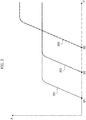
- Figure 2 is a diagram illustrating the various operating conditions of the valve 3 as a function of the electrical power supply voltage.
- the degree of opening of each of the three outlets 301, 302, 303 of the valve 3 is represented in the form of a lift A of a movable element of the valve upon variation in the electrical power supply voltage U.
- U1 Below a value U1, the valve 3 is in a completely closed condition.
- the power supply voltage U exceeds the value U1
- the first outlet 301 is progressively opened, until la condition of complete opening is reached.
- Above a voltage value U2 also in the second outlet 302 there is a progressive opening until a completely open condition is reached.
- the third outlet 303 is opened progressively until reaching a completely open condition when the power supply voltage exceeds a third value U3.
- the energizing of the solenoid of the distribution valve 3 is controlled by the electronic control unit E which may be the electronic control unit controlling the operation of the engine 2.
- the electronic control unit E can also provide control of the electric motor driving the pump 5, in the event that said pump is driven by an electric motor.
- two temperature sensors 605, 606 are provided in the conduit 109, respectively upstream and downstream from the tank 6.
- the output signals of the temperature sensors 605, 606 are sent to the electronic control unit E.
- the cooling system furthermore comprises at least one sensor 11 of the temperature of the coolant leaving the engine.
- the electronic control unit E is programmed so that, after a start of the internal combustion engine, a number of different operating phases are actuated in succession upon increasing of the temperature value of the coolant as detected by the sensor 11.
- the electronically controlled distribution valve is maintained in its closed condition, so that the coolant leaving the engine 2 immediately after the start of the engine flows entirely from the conduit 102 to the conduit 109, causing the heat exchanger 4 to be fed with the quantity of relatively warm coolant previously stored in the thermally insulated tank 6.
- the tank 6 is typically able to maintain the temperature of the coolant stored in it at a value higher than the ambient temperature, even during prolonged stops of the motor-vehicle with the engine inactive. As noted above, when the engine is started, the coolant leaving the engine 2, still relatively cold, is taken entirely to the tank 6, which is therefore emptied of the warm coolant previously stored therein. The warm coolant stored in the tank 6 is therefore fed to the heat exchanger 4.
- the heat exchanger functions as a heater of the lubricating oil and the quantity of warm liquid previously stored in the tank 6 makes it possible to accelerate the warm-up phase of the engine oil so as to reduce the time needed to bring the oil up to the ideal temperature in order to minimize engine frictions and, consequently, fuel consumption.
- the aforesaid first phase in which the tank 6 is emptied of the warm liquid previously contained therein may have a duration on the order of 20 seconds.
- the electronic control unit E is programmed to compare the temperature values coming from the temperature sensors 605, 606. When the control unit detects that these temperature values are identical within a predetermined tolerance margin, it deduces that the entire quantity of relatively warm coolant previously stored in the tank 6 has left the tank. This condition is considered to be the conclusion of the first operating phase of the system.
- the electronic control unit E triggers switching of the valve 3 from the closed condition to the aforesaid first opened condition, in which only the first outlet 301 communicates with the inlet 300 of the valve.
- this condition basically the entire flow of the coolant leaving the engine 2 flows from the conduit 102 into the conduit 103. Therefore, the entire flow of the coolant leaving the engine, also in this second operating phase, is directed to the heat exchanger 4 which in this phase acts as a heater of the lubricating oil, so as to allow reaching the ideal operating temperature of the oil as quickly as possible.
- the reaching of the end of this second operating phase can be detected as an exceeding of a predetermined threshold value detected by the temperature sensor 11.
- the electronic control unit E triggers switching of the valve 3 to a second opened condition, in which only the outlets 301 and 302 communicate with the inlet 300.
- a portion of the coolant coming from the conduit 102 continues to be fed to the heat exchanger 4, which will thus maintain the temperature of the engine lubricating oil at the desired value, as the the engine warms-up, while another portion of the coolant flows in the conduit 110, to activate the heater 8 of the passenger compartment.
- a third operating phase which can be initiated when the temperature value detected by the sensor 11 exceeds a second threshold value greater than the first threshold value, the valve 3 is switched to a third opened condition, in which all three outlets 301, 302, 303 communicate with the inlet 300.
- the coolant of the engine is also fed to the radiator 9 of the motor vehicle, where it is cooled prior to returning to the engine 2.
- the constricted cross-section 7 in the conduit 109 ensures that the coolant 102 is taken at least for the most part to the outlet 301 and/or to the outlet 302 and/or to the outlet 303, when the valve 3 is in one of its opened conditions.
- the electronic control unit E is designed to receive a signal indicative of a switch-off command of the engine and consequently to switch the valve 3 to its closed condition, so as to direct the entire flow of the coolant leaving the engine to the tank 6.
- the electronic control unit E will be able to detect the complete filling of the tank 6 with warm coolant, by checking that the temperature values detected by the sensors 605, 606 are substantially identical. Once reaching of this condition is detected, the electronic control unit E can enable the actual shutdown of the engine.
- the phase of filling the tank 6 with warm coolant can be activated even after the actual shutdown of the engine, since even when the engine is shut down the electronic control unit E can trigger the activation of the electric motor driving the pump 5.
- the pump is controlled by the engine 2, it is necessary to carry out the phase of filling the tank 6 with warm liquid before the engine is actually shut down.
- the constricted cross-section 7 in the conduit 109 enables a proper operation of the system without the need to provide the complication of an intercepting valve in the conduit 109.
- the same result can be achieved by arranging, in place of the constricted cross-section 7 in the conduit 109, a labyrinth pathway (not shown).
- the labyrinth pathway can be comprised, for example, of a tubing arranged in a winding course directly around the wall of the tank 6, on its outside.
Landscapes
- Engineering & Computer Science (AREA)
- Mechanical Engineering (AREA)
- General Engineering & Computer Science (AREA)
- Chemical & Material Sciences (AREA)
- Combustion & Propulsion (AREA)
- Life Sciences & Earth Sciences (AREA)
- Atmospheric Sciences (AREA)
- Lubrication Of Internal Combustion Engines (AREA)
Description
- The present invention relates to cooling systems for motor-vehicle internal combustion engines of the type comprising:
- a circuit for an engine coolant, including an inner circuit portion internal to the engine and an outer circuit portion external to the engine,
- a thermally insulated tank for the engine coolant, connected to said outer portion of the cooling circuit and adapted to maintain a determined quantity of coolant at a temperature higher than the ambient temperature when the engine is inactive, so as to enable said quantity of coolant at a temperature higher than ambient temperature to be used after a subsequent start of the engine, during an engine warm-up phase,
- said outer circuit portion further including:
- a pump to activate circulation of the coolant in the circuit,
- an oil cooler for cooling the engine lubricating oil,
- a heater for heating the passenger compartment,
- a radiator for cooling the coolant,
- an electronically controlled distribution valve to control the flow of coolant in the outer circuit portion, so as to direct this flow towards the lubricating oil cooler and/or towards the passenger compartment heater and/or towards the radiator, and
- an electronic control unit to control the operating condition of said electronically controlled distribution valve as a function of one or more operating parameters including at least one detected value of the coolant temperature,
- wherein said electronically controlled distribution valve has an inlet connected to a first conduit supplying the coolant coming out from the engine.
- In cooling systems of the above indicated type, the aforesaid thermally insulated tank is used to accelerate engine warm-up phase after a cold start, due to the possibility of using the relatively warm coolant contained therein. Systems of this type are known, for example, from documents
WO2007/113419 ,US 2005/229873 ,US 5,299,630 ,US 2,401,510 ,JP 3353236 JP 5189461 JP 2002266679 JP 2003 322019 JP H10 309933 JP 3843499 JP 2008 082225 - The object of the present invention is to provide a cooling system of the above indicated type in which the warm-up phase after a cold start of the engine is accelerated and in which furthermore an operating condition of the engine allowing minimal fuel consumption is achieved in the shortest possible time.
- In order to achieve the above object, the present invention deals with a cooling system for an internal combustion engine of a motor vehicle having all the features indicated in the beginning of the present specification and further characterized in that:
- said thermally insulated tank is placed in a second conduit connecting said first conduit to an inlet of said engine lubricating oil cooler,
- said electronically controlled distribution valve comprises:
- a first outlet connected to said inlet of the engine lubricating oil cooler,
- a second outlet connected to an inlet of said passenger compartment heater, and
- a third outlet connected to an inlet of said radiator,
- said electronically controlled distribution valve being selectively switchable to one of the following operating conditions:
- a closed condition, in which all of said first, second and third outlets are isolated with respect to said inlet of the valve,
- a first opened condition, in which only said first outlet communicates with the inlet of the valve,
- a second opened condition, in which only said first and second outlets communicate with the inlet of the valve, and
- a third opened condition, in which all said first, second and third outlets communicate with said inlet of the valve,
- said electronic control unit being programmed so that, after the internal combustion engine is started, the following operating phases are actuated in sequence, as the detected temperature of the engine coolant increases:
- a first phase in which the electronically controlled distribution valve is maintained in its closed condition, so that the coolant leaving the engine flows entirely from said first conduit to said second conduit, causing the quantity of coolant previously stored within the thermally insulated tank to be fed to the engine lubricating oil cooler,
- a second phase in which the electronically controlled distribution valve is maintained in its first opened condition, so that the coolant leaving the engine is still fed solely to the engine lubricating oil cooler,
- a third phase in which the electronically controlled distribution valve is maintained in its second opened condition, so that the coolant leaving the engine is fed both to the engine lubricating oil cooler and to the passenger compartment heater, and
- a fourth phase in which the electronically controlled distribution valve is maintained in its third opened condition, so that the coolant leaving the engine is fed both to the engine lubricating oil cooler and to the passenger compartment heater and to the radiator.
- Due to the above described arrangement, the system according to the invention is therefore able to give a priority to the engine lubricating oil cooler in the initial phase of engine warm-up, after a cold start. In this phase, the heat exchanger constituting the lubricating oil cooler is used to heat the lubricating oil in order to bring it up to an ideal temperature to guarantee minimum frictions in the engine and consequently minimum fuel consumption, in the shortest possible time.
- According to another characteristic of the invention, the inlet of said thermally insulated tank communicates with said first conduit through a passage of restricted cross-section and/or a labyrinth pathway, so that when the electronically controlled distribution valve is in one of its opened conditions the coolant leaving the engine tends to flow toward the outlets of the valve, rather than towards said thermally insulated tank.
- Thanks to this characteristic, the system according to the invention can be provided with no intercepting valve in the communication of the inlet of the thermally insulated tank with the first conduit feeding the coolant from the engine.
- In one sample embodiment of the cooling system according to the invention, two temperature sensors are provided in said second conduit, respectively arranged upstream and downstream of the thermally insulated tank, and the electronic control unit is configured to receive the output signals from said sensors and to command switching from said first operating phase to said second operating phase when the temperature values detected by said sensors become substantially identical. This condition in fact indicates that in the first phase following starting of the engine the warm coolant previously stored in the thermally insulated tank has completely left the tank to flow towards the engine lubricating oil cooler, while the tank continues to receive the flow of coolant leaving the engine, so that the temperature of the coolant at the inlet of the tank becomes substantially identical to the temperature of the coolant at the outlet of the tank.
- Again in the case of the preferred sample embodiment, switching from said second operating phase to said third operating phase is triggered by the electronic control unit when the detected value of the coolant temperature exceeds a first threshold value, while switching from the third operating phase to the fourth operating phase is triggered by said electronic control unit when the detected value of the coolant temperature exceeds a second threshold value, greater than said first threshold value. Naturally, switching from one operating condition to the next is implemented only when the respective thermal condition has been achieved. As an indicator parameter to be used for switching of the various operating phases of the system, one can use, instead of, or in addition to, the detected value of the coolant temperature, any other suitable parameter, such as the temperature of the engine lubricating oil or the temperature of the metal body of the engine.
- Further characteristics and advantages of the present invention shall emerge from the following description with respect to the enclosed drawings, provided merely as a nonlimiting example, where:
-
Figure 1 is a diagram of a preferred embodiment of the cooling system according to the invention, and -
Figure 2 is a diagram showing the various operating conditions of the electronically controlled distribution valve which is part of the cooling system according to the invention. - With regard to
Figure 1 ,reference number 1 generally indicates a cooling system for aninternal combustion engine 2 of a motor vehicle. - The
cooling system 1 comprises a circuit for a coolant of the engine, including a section ofcircuit 100 internal to theengine 2, and a section ofcircuit 101 external to the engine. - The section of
circuit 101 external to the engine includes afirst conduit 102 which feeds the coolant leaving theengine 2 to an electronically controlleddistribution valve 3 of any known kind. - The
distribution valve 3 has aninlet 300 which receives the coolant fed by thefirst conduit 102, afirst outlet 301, asecond outlet 302 and athird outlet 303. - In
Figure 1 , the arrows along the connecting conduits of the hydraulic circuit indicate the direction of flow of the coolant. - The
first outlet 301 of thedistribution valve 3 communicates with aconduit 103 connected to theinlet 401 of a heat exchanger 4 of any known kind, which is used as a cooler of the engine lubricating oil. For this purpose, the heat exchanger 4 receives a flow of both the coolant coming from theconduit 103 and a flow of engine lubricating oil, which is fed from theengine 2 to the heat exchanger 4 through aconduit 104, and which returns from the heat exchanger 4 to theengine 2 through aconduit 105. - The coolant passing through the heat exchanger 4 emerges by an
outlet 402 of the heat exchanger 4 to flow through aconduit 106 and aconduit 107 into areturn conduit 108 which brings the coolant back to theengine 2. - In the
return conduit 108 there is arranged apump 5 serving to activate the circulation of the coolant in the circuit. - The
pump 5 can be provided to be actuated by the shaft of theinternal combustion engine 2 or it can be controlled by a respective electric motor, whose operation is controlled by an electronic control unit E. -
Reference number 109 indicates a second conduit connecting thefirst conduit 102 to theconduit 103 communicating with theinlet 401 of the cooler 4 of the engine lubricating oil. - In the
second conduit 109 there is arranged a thermally insulatedtank 6, having aninlet 601 and anoutlet 602. Thetank 6 can be fabricated in any known manner. It is typically comprised of a container, such as one of cylindrical shape, having a thermally insulating wall.Check valves conduit 109 upstream and downstream of thetank 7 to allow a flow in theconduit 109 solely in the direction of theconduit 103 connected to theinlet 401 of the heat exchanger 4 constituting the cooler of the engine lubricating oil.Reference 7 shows schematically a constricted cross-section disposed in the connection between theinlet 601 of thetank 6 and theconduit 102 feeding the coolant leaving the engine. In the system calibration phase, theconstricted cross-section 7 is dimensioned so as to ensure that, when thedistribution valve 3 is in an opened condition in which one or more of itsoutlets inlet 300, the coolant leaving the engine and flowing in theconduit 102 tends to continue toward one or more outlets of thevalve 3 instead of flowing through theconduit 109. Vice versa, when thevalve 7 is in the closed condition in which all three of itsoutlets inlet 300, the coolant coming from theconduit 102 is forced to flow through theconduit 109, through the thermally insulatedtank 6 and the heat exchanger 4 making up the cooler of the engine lubricating oil. - Returning to the
distribution valve 3, itssecond outlet 302 communicates with aconduit 110 connected to theinlet 801 of aheat exchanger 8 utilized as a heater of the conditioning air of the passenger compartment of the motor vehicle. Anoutlet 802 of theheat exchanger 8 communicates with aconduit 111 which takes the coolant leaving theheat exchanger 8 back to theengine 2, through theconduits pump 5. - A
third outlet 303 of thevalve 3 communicates with aconduit 112 connected to aninlet 901 of aradiator 9 of the motor vehicle. Theoutlet 902 of theradiator 9 is connected to aconduit 113 by which the coolant leaving theradiator 9 returns to the engine, through theconduit 108 and thepump 5. - The
valve 3, finally, has afourth outlet 304 connected to aconduit 114 which communicates with anexpansion vessel 10, according to the conventional engineering. Theexpansion vessel 10 is provided, again in conventional manner, with adirect communication 1001 with the circuit of the coolant of the engine. In theconduit 114 there is disposed acheck valve 1002 which allows a flow in theconduit 114 only in the direction of theexpansion vessel 10. - The
distribution valve 3 is of any known type able to be selectively switched to one of the following operating positions: - a closed condition, in which all three
outlets inlet 300; - a first open condition, in which only the
first outlet 301 communicates with theinlet 300; - a second open condition, in which only the two
outlets inlet 300; and - a third open condition, in which all three
outlets inlet 300. - The
valve 3 is a solenoid valve and the switching to the various operating conditions is achieved by a progressive increase of the electrical power supply voltage of the solenoid.Figure 2 is a diagram illustrating the various operating conditions of thevalve 3 as a function of the electrical power supply voltage. In the diagram ofFigure 2 , the degree of opening of each of the threeoutlets valve 3 is represented in the form of a lift A of a movable element of the valve upon variation in the electrical power supply voltage U. Below a value U1, thevalve 3 is in a completely closed condition. When the power supply voltage U exceeds the value U1, thefirst outlet 301 is progressively opened, until la condition of complete opening is reached. Above a voltage value U2, also in thesecond outlet 302 there is a progressive opening until a completely open condition is reached. Finally, also thethird outlet 303 is opened progressively until reaching a completely open condition when the power supply voltage exceeds a third value U3. - The energizing of the solenoid of the
distribution valve 3 is controlled by the electronic control unit E which may be the electronic control unit controlling the operation of theengine 2. As noted, the electronic control unit E can also provide control of the electric motor driving thepump 5, in the event that said pump is driven by an electric motor. - Furthermore, in the sample embodiment illustrated here, two
temperature sensors conduit 109, respectively upstream and downstream from thetank 6. The output signals of thetemperature sensors - According to a conventional technique, the cooling system furthermore comprises at least one
sensor 11 of the temperature of the coolant leaving the engine. - According to the invention, the electronic control unit E is programmed so that, after a start of the internal combustion engine, a number of different operating phases are actuated in succession upon increasing of the temperature value of the coolant as detected by the
sensor 11. - In a first phase, the electronically controlled distribution valve is maintained in its closed condition, so that the coolant leaving the
engine 2 immediately after the start of the engine flows entirely from theconduit 102 to theconduit 109, causing the heat exchanger 4 to be fed with the quantity of relatively warm coolant previously stored in the thermally insulatedtank 6. Thetank 6 is typically able to maintain the temperature of the coolant stored in it at a value higher than the ambient temperature, even during prolonged stops of the motor-vehicle with the engine inactive. As noted above, when the engine is started, the coolant leaving theengine 2, still relatively cold, is taken entirely to thetank 6, which is therefore emptied of the warm coolant previously stored therein. The warm coolant stored in thetank 6 is therefore fed to the heat exchanger 4. In this phase, the heat exchanger functions as a heater of the lubricating oil and the quantity of warm liquid previously stored in thetank 6 makes it possible to accelerate the warm-up phase of the engine oil so as to reduce the time needed to bring the oil up to the ideal temperature in order to minimize engine frictions and, consequently, fuel consumption. - For example, in the case of a tank with a capacity of two liters, the aforesaid first phase in which the
tank 6 is emptied of the warm liquid previously contained therein may have a duration on the order of 20 seconds. The electronic control unit E is programmed to compare the temperature values coming from thetemperature sensors tank 6 has left the tank. This condition is considered to be the conclusion of the first operating phase of the system. - At the end of this first operating phase, the electronic control unit E triggers switching of the
valve 3 from the closed condition to the aforesaid first opened condition, in which only thefirst outlet 301 communicates with theinlet 300 of the valve. In this condition, as mentioned, basically the entire flow of the coolant leaving theengine 2 flows from theconduit 102 into theconduit 103. Therefore, the entire flow of the coolant leaving the engine, also in this second operating phase, is directed to the heat exchanger 4 which in this phase acts as a heater of the lubricating oil, so as to allow reaching the ideal operating temperature of the oil as quickly as possible. The reaching of the end of this second operating phase can be detected as an exceeding of a predetermined threshold value detected by thetemperature sensor 11. However, it is also possible to provide a sensor of the lubricating oil temperature, and to design the electronic control unit E to receive the output signal of this lubricating oil temperature sensor and to consider the second operating phase to be concluded when the value detected for the lubricating oil temperature reaches a predetermined threshold value. - Whatever solution is chosen, once the conclusion of the second operating phase is detected the electronic control unit E triggers switching of the
valve 3 to a second opened condition, in which only theoutlets inlet 300. In this phase, therefore, a portion of the coolant coming from theconduit 102 continues to be fed to the heat exchanger 4, which will thus maintain the temperature of the engine lubricating oil at the desired value, as the the engine warms-up, while another portion of the coolant flows in theconduit 110, to activate theheater 8 of the passenger compartment. - In a third operating phase, which can be initiated when the temperature value detected by the
sensor 11 exceeds a second threshold value greater than the first threshold value, thevalve 3 is switched to a third opened condition, in which all threeoutlets inlet 300. In this phase, the coolant of the engine is also fed to theradiator 9 of the motor vehicle, where it is cooled prior to returning to theengine 2. - As indicated above, the constricted
cross-section 7 in theconduit 109 ensures that thecoolant 102 is taken at least for the most part to theoutlet 301 and/or to theoutlet 302 and/or to theoutlet 303, when thevalve 3 is in one of its opened conditions. On the other hand, when theinternal combustion engine 2 is switched-off, it is necessary to activate a phase in which the thermally insulatedtank 6 is again refilled with coolant at elevated temperature. To accomplish this result, the electronic control unit E is designed to receive a signal indicative of a switch-off command of the engine and consequently to switch thevalve 3 to its closed condition, so as to direct the entire flow of the coolant leaving the engine to thetank 6. Once again, the electronic control unit E will be able to detect the complete filling of thetank 6 with warm coolant, by checking that the temperature values detected by thesensors - In the event that the
pump 5 is driven by an electric motor associated therewith, the phase of filling thetank 6 with warm coolant can be activated even after the actual shutdown of the engine, since even when the engine is shut down the electronic control unit E can trigger the activation of the electric motor driving thepump 5. However, in the case where the pump is controlled by theengine 2, it is necessary to carry out the phase of filling thetank 6 with warm liquid before the engine is actually shut down. - The provision of the constricted
cross-section 7 in theconduit 109 enables a proper operation of the system without the need to provide the complication of an intercepting valve in theconduit 109. On the other hand, the same result can be achieved by arranging, in place of the constrictedcross-section 7 in theconduit 109, a labyrinth pathway (not shown). In this case, the labyrinth pathway can be comprised, for example, of a tubing arranged in a winding course directly around the wall of thetank 6, on its outside. - Reverting to the
distribution valve 3, the communication of this valve with theconduit 114 connected to theexpansion vessel 10 is controlled in a conventional manner, by an on/off element sensitive to a pressure difference. - Naturally, while the principle of the invention remains the same, the details of construction and the embodiments may widely vary with respect to what has been described and illustrated, merely as an example, without thereby departing from the scope of the present invention, as it is defined in the following claims.
Claims (14)
- Cooling system for a motor-vehicle internal combustion engine, said system comprising:- a circuit (1) for an engine coolant, including an inner circuit portion (100) internal to the engine (2) and an outer circuit portion (101) external to the engine (2),- a thermally insulated tank (6) for the engine coolant, connected to said outer portion (101) of the cooling circuit (1) and adapted to maintain a determined quantity of coolant at a temperature higher than the ambient temperature when the engine (2) is inactive, so as to enable said quantity of coolant at a temperature higher than ambient temperature to be used after a subsequent start of the engine (2), during an engine warm-up stage,- said outer circuit portion (101) further including:- a pump (5) to activate circulation of the coolant in the circuit (1),- an oil cooler (4) for cooling the engine lubricating oil,- a heater (8) for heating the passenger compartment,- a radiator (9) for cooling the coolant,- an electronically controlled distribution valve (3) to control the flow of coolant in the outer circuit portion (101), so as to direct this flow towards the lubricating oil cooler (4) and/or towards the passenger compartment heater (8) and/or towards the radiator (9), and- an electronic control unit (E) to control the operating condition of said electronically controlled distribution valve (3) as a function of one or more operating parameters including at least one detected value of the coolant temperature,- wherein said electronically controlled distribution valve (3) has an inlet (300) connected to a first conduit (102) supplying the coolant coming out from the engine (2),said system being characterized in that:- said thermally insulated tank (6) is placed in a second conduit (109) connecting said first conduit (102) to an inlet (401) of said engine lubricating oil cooler (4),- said electronically controlled distribution valve (3) comprises:- a first outlet (301) connected to said inlet (401) of the engine lubricating oil cooler (4),- a second outlet (302) connected to an inlet (801) of said passenger compartment heater (8), and- a third outlet (303) connected to an inlet (901) of said radiator (9),- said electronically controlled distribution valve (3) being selectively switchable to one of the following operating conditions:- a closed condition, in which all of said first, second and third outlets (301, 302, 303) are isolated with respect to said inlet (300) of the valve (3),- a first opened condition, in which only said first outlet (301) communicates with the inlet (300) of the valve (3),- a second opened condition, in which only said first and second outlets (301, 302) communicate with the inlet (300) of the valve (3), and- a third opened condition, in which all said first, second and third outlets (301, 302, 303) communicate with said inlet (300) of the valve (3),- said electronic control unit (E) being programmed so that, after the internal combustion engine (2) is started, the following operating phases are actuated in sequence, as the detected temperature of the engine coolant increases:- a first stage in which the electronically controlled distribution valve (3) is maintained in its closed condition, so that the coolant leaving the engine (2) flows entirely from said first conduit (102) to said second conduit (109), causing the quantity of coolant previously stored within the thermally insulated tank (6) to be fed to the engine lubricating oil cooler (4),- a second stage in which the electronically controlled distribution valve (3) is maintained in its first opened condition, so that the coolant leaving the engine is still fed solely to the engine lubricating oil cooler (4),- a third stage in which the electronically controlled distribution valve (3) is maintained in its second opened condition, so that the coolant leaving the engine is fed both to the engine lubricating oil cooler (4) and to the passenger compartment heater (8), and- a fourth stage in which the electronically controlled distribution valve (3) is maintained in its third opened condition, so that the coolant leaving the engine (2) is fed both to the engine lubricating oil cooler (4) and to the passenger compartment heater (8) and to the radiator (9).
- Cooling system according to claim 1, characterized in that the inlet (601) of said thermally insulated tank (6) communicates with said first conduit (102) through a passage with a restricted cross-section (7) and/or through a labyrinth path, so that when the electronically controlled distribution valve (3) is in one of its opened conditions the coolant leaving the engine tends to flow toward the outlets of the valve (3), rather than towards said thermally insulated tank (6).
- Cooling system according to claim 1, characterized in that two temperature sensors (605, 606) are provided in said second conduit (109), respectively arranged upstream and downstream of the thermally insulated tank (6), and the electronic control unit (E) is configured to receive the output signals from said temperature sensors (605, 606) and to cause a switching from said first operating stage to said second operating stage when the temperature values detected by said sensors (605, 606) become substantially the same.
- Cooling system according to claim 1, characterized in that said electronic control unit (E) is configured to cause a switching from said second operating stage to said third operating stage when said detected value of the coolant temperature exceeds a first threshold value, and to cause a switching from said third operating stage to said fourth operating stage when the detected value of the coolant temperature exceeds a second threshold value, greater than said first threshold value.
- Cooling system according to claim 1, characterized in that the electronic control unit (E) is configured to receive a signal indicative of an engine switch-off command to switch-off the internal combustion engine (2), as well as to consequently cause switching of the electronically controlled distribution valve (3) to its closed condition, so that warm coolant leaving the internal combustion engine (2) is directed to said thermally insulated tank (6).
- Cooling system according to claim 5, characterized in that the pump (5) is actuated by the internal combustion engine (2) and said electronic control unit (E) is configured to enable switch-off of the engine only after detecting a filling of the thermally insulated tank (6) with warm coolant coming out from the engine (2).
- Cooling system according to claim 5, characterized in that the pump (5) is actuated electrically, and said switching of the valve (3) to the closed condition to obtain a filling of the thermally insulated tank (6) with warm coolant is triggered after the internal combustion engine has been switched-off.
- Cooling system according to claim 2, characterized in that the inlet (601) of the thermally insulated tank (6) communicates with the first conduit (102) through a labyrinth path defined by a conduit arranged in a winding path around the body of the thermally insulated tank (6).
- Method for controlling a cooling system of an internal combustion engine of a motor vehicle, wherein said system comprises:- a circuit (1) for an engine coolant, including an inner circuit portion (100) internal to the engine (2) and an outer circuit portion (101) external to the engine (2),- a thermally insulated tank (6) for the engine coolant, connected to said outer portion (101) of the cooling circuit (1) and able to maintain a determined quantity of coolant at a temperature higher than the ambient temperature when the engine (2) is inactive, to allow the use of such quantity of coolant at a temperature higher than ambient temperature after a subsequent starting of the engine (2), during the engine warm-up phase,- said outer circuit portion (101) further including:- a pump (5) to activate the circulation of the coolant in the circuit (1),- an oil cooler (4) for cooling the engine lubricating oil,- a heater (8) for heating the passenger compartment,- a radiator (9) for cooling the coolant,- an electronically controlled distribution valve (3) to control the flow of coolant in the outer circuit portion (101), so as to direct this flow towards the lubricating oil cooler (4) and/or towards the passenger compartment heater (8) and/or towards the radiator (9), and- the operating condition of said electronically controlled distribution valve (3) being controlled as a function of one or more operating parameters, including at least one detected value of the coolant temperature,,- wherein said electronically controlled distribution valve (3) has an inlet (300) connected to a first conduit (102) supplying the coolant coming out from the engine (2),said method being characterized in that:- said thermally insulated tank (6) is placed in a second conduit (109) connecting said first conduit (102) to an inlet (401) of said engine lubricating oil cooler (4),- said electronically controlled distribution valve (3) comprises:- a first outlet (301) connected to said inlet (401) of the engine lubricating oil cooler (4),- a second outlet (302) connected to an inlet (801) of said passenger compartment heater (8), and- a third outlet (303) connected to an inlet (901) of said radiator (9),- said electronically controlled distribution valve (3) being selectively switchable to one of the following operating conditions:- a closed condition, in which all of said first, second and third outlets (301, 302, 303) are isolated with respect to said inlet (300) of the valve (3),- a first opened condition, in which only said first outlet (301) communicates with the inlet (300) of the valve (3),- a second opened condition, in which only said first and second outlets (301, 302) communicate with the inlet (300) of the valve (3), and- a third opened condition, in which all said first, second and third outlets (301, 302, 303) communicate with said inlet (300) of the valve (3),- after the internal combustion engine (2) is started, the following operating phases are actuated in succession, as the detected temperature of the engine coolant increases:- a first phase in which the electronically controlled distribution valve (3) is maintained in its closed condition, so that the coolant leaving the engine (2) flows entirely from said first conduit (102) to said second conduit (109), causing the quantity of coolant previously stored within the thermally insulated tank (6) to be fed to the engine lubricating oil cooler (4),- a second phase in which the electronically controlled distribution valve (3) is maintained in its first opened condition, so that the coolant leaving the engine is still fed solely to the engine lubricating oil cooler (4),- a third phase in which the electronically controlled distribution valve (3) is maintained in its second opened condition, so that the coolant leaving the engine is fed both to the engine lubricating oil cooler (4) and to the passenger compartment heater (8), and- a fourth phase in which the electronically controlled distribution valve (3) is maintained in its third opened condition, so that the coolant leaving the engine (2) is fed both to the engine lubricating oil cooler (4) and to the passenger compartment heater (8) and to the radiator (9).
- Method according to claim 9, characterized in that two temperature sensors (605, 606) are provided in said second conduit (109), respectively arranged upstream and downstream from the thermally insulated tank (6), and a switching from said first operating phase to said second operating phase is triggered when the temperature values detected by said sensors (605, 606) become substantially identical.
- Method according to claim 9 or 10, characterized in that said electronic control unit (E) is configured to cause a switching from said second operating phase to said third operating phase when said detected value of the coolant temperature exceeds a first threshold value, and to cause a switching from said third operating stage to said fourth operating stage when the detected value of the coolant temperature exceeds a second threshold value, greater than said first threshold value.
- Method according to claim 9, characterized in that when a command to switch-off the internal combustion engine (2) is received, warm coolant leaving the internal combustion engine (2) is taken to said thermally insulated tank (6).
- Method according to claim 12, characterized in that the pump (5) is actuated by the internal combustion engine (2) and in that switch-off of the engine is enabled only after having detecting a filling of the thermally insulated tank (6) with warm coolant leaving the engine (2).
- Method according to claim 12, characterized in that the pump (5) is actuated electrically and in that the thermally insulated tank (6) is filled with warm coolant after the internal combustion engine has been switched-off.
Priority Applications (2)
| Application Number | Priority Date | Filing Date | Title |
|---|---|---|---|
| EP16169784.2A EP3246541B1 (en) | 2016-05-16 | 2016-05-16 | Cooling system for an internal combustion engine of a motor vehicle |
| US15/438,808 US10030551B2 (en) | 2016-05-16 | 2017-02-22 | Cooling system for an internal combustion engine of a motor vehicle |
Applications Claiming Priority (1)
| Application Number | Priority Date | Filing Date | Title |
|---|---|---|---|
| EP16169784.2A EP3246541B1 (en) | 2016-05-16 | 2016-05-16 | Cooling system for an internal combustion engine of a motor vehicle |
Publications (2)
| Publication Number | Publication Date |
|---|---|
| EP3246541A1 EP3246541A1 (en) | 2017-11-22 |
| EP3246541B1 true EP3246541B1 (en) | 2018-07-18 |
Family
ID=56112821
Family Applications (1)
| Application Number | Title | Priority Date | Filing Date |
|---|---|---|---|
| EP16169784.2A Active EP3246541B1 (en) | 2016-05-16 | 2016-05-16 | Cooling system for an internal combustion engine of a motor vehicle |
Country Status (2)
| Country | Link |
|---|---|
| US (1) | US10030551B2 (en) |
| EP (1) | EP3246541B1 (en) |
Cited By (1)
| Publication number | Priority date | Publication date | Assignee | Title |
|---|---|---|---|---|
| EP3623183A1 (en) | 2018-09-11 | 2020-03-18 | C.R.F. Società Consortile per Azioni | A system for thermal management of the components of a hybrid vehicle |
Families Citing this family (5)
| Publication number | Priority date | Publication date | Assignee | Title |
|---|---|---|---|---|
| EP3369907B1 (en) | 2017-03-03 | 2019-04-10 | C.R.F. Società Consortile per Azioni | Cooling system for an internal combustion engine of a motor-vehicle |
| CN108678850B (en) * | 2018-07-16 | 2023-10-24 | 河北工业大学 | Intelligent cylinder sleeve thermal management system using lubricating oil |
| CN111042891B (en) * | 2019-12-31 | 2021-08-03 | 宁波吉利罗佑发动机零部件有限公司 | Extended program lubrication management system, lubrication management method and vehicle |
| CN115013114A (en) * | 2022-06-13 | 2022-09-06 | 潍柴动力股份有限公司 | An engine preheating system and method |
| CN118572265B (en) * | 2024-08-01 | 2024-11-19 | 比亚迪股份有限公司 | Battery thermal management system for charging station, charging station and control method |
Family Cites Families (18)
| Publication number | Priority date | Publication date | Assignee | Title |
|---|---|---|---|---|
| JP2003322019A (en) | 2002-04-30 | 2003-11-14 | Denso Corp | Cooling system for internal combustion engine for vehicles |
| US2401510A (en) | 1944-03-25 | 1946-06-04 | Rowley Kennard Albert | Engine cooling system |
| JPS6183405A (en) * | 1984-09-29 | 1986-04-28 | Nissan Motor Co Ltd | Lubricating oil cooler |
| DE4136910C2 (en) | 1991-11-09 | 1994-10-20 | Schatz Oskar | Method for quickly setting the operating temperature of a mass by means of a flowable or free-flowing heat transfer medium, in particular for rapid heating of a motor vehicle engine during a cold start |
| JP3353236B2 (en) | 1995-02-24 | 2002-12-03 | 株式会社日本自動車部品総合研究所 | Internal combustion engine cooling system |
| JP3525538B2 (en) * | 1995-03-08 | 2004-05-10 | 株式会社デンソー | Cooling system for internal combustion engine for vehicles |
| JP3843499B2 (en) | 1996-08-30 | 2006-11-08 | 株式会社デンソー | Cooling water circuit for internal combustion engine |
| US5896833A (en) * | 1996-08-30 | 1999-04-27 | Denso Corporation | Cooling water circuit system and cooling water control valve |
| JPH10309933A (en) | 1997-05-13 | 1998-11-24 | Denso Corp | Vehicle heating system |
| US6520136B2 (en) * | 2000-09-13 | 2003-02-18 | Toyota Jidosha Kabushiki Kaisha | Warm-up control device for internal-combustion engine and warm-up control method |
| JP2002266679A (en) | 2001-03-06 | 2002-09-18 | Denso Corp | Control device for internal combustion engine |
| GB0310120D0 (en) * | 2003-05-02 | 2003-06-04 | Ford Global Tech Llc | Engine cooling systems |
| DE10344018B4 (en) | 2003-09-15 | 2016-12-22 | Mahle International Gmbh | Cooling system set up for an internal combustion engine with a hot water tank |
| FR2899647B1 (en) * | 2006-04-05 | 2011-09-16 | Renault Sas | SYSTEM AND METHOD FOR CONTROLLING THE TEMPERATURE OF A SUPERCHARGED MOTOR AND COMPRISING A SUPER-AIR AIR RADIATOR |
| JP2008082225A (en) | 2006-09-27 | 2008-04-10 | Mazda Motor Corp | Engine cooling system |
| US7533636B2 (en) * | 2007-04-30 | 2009-05-19 | General Electric Company | System, method, and computer readable media for controlling cooling in a diesel fueled power generation unit |
| JP5189461B2 (en) | 2008-11-05 | 2013-04-24 | トヨタ自動車株式会社 | Cooling device for internal combustion engine |
| DE102011084632B4 (en) * | 2011-10-17 | 2015-03-05 | Ford Global Technologies, Llc | Method for heating an internal combustion engine and internal combustion engine for carrying out such a method |
-
2016
- 2016-05-16 EP EP16169784.2A patent/EP3246541B1/en active Active
-
2017
- 2017-02-22 US US15/438,808 patent/US10030551B2/en active Active
Non-Patent Citations (1)
| Title |
|---|
| None * |
Cited By (2)
| Publication number | Priority date | Publication date | Assignee | Title |
|---|---|---|---|---|
| EP3623183A1 (en) | 2018-09-11 | 2020-03-18 | C.R.F. Società Consortile per Azioni | A system for thermal management of the components of a hybrid vehicle |
| US11091007B2 (en) | 2018-09-11 | 2021-08-17 | C.R.F. Societè Consortile per Azioni | System for thermal management of the components of a hybrid vehicle |
Also Published As
| Publication number | Publication date |
|---|---|
| US20170328246A1 (en) | 2017-11-16 |
| EP3246541A1 (en) | 2017-11-22 |
| US10030551B2 (en) | 2018-07-24 |
Similar Documents
| Publication | Publication Date | Title |
|---|---|---|
| US10030551B2 (en) | Cooling system for an internal combustion engine of a motor vehicle | |
| EP3369907B1 (en) | Cooling system for an internal combustion engine of a motor-vehicle | |
| KR100305358B1 (en) | Cooling system for internal combustion engine | |
| EP2864607B1 (en) | Fluid flow control device | |
| US7721683B2 (en) | Integrated engine thermal management | |
| US8291870B2 (en) | Cooling systems | |
| US6966278B2 (en) | Electronically controlled thermostat | |
| CN102529638B (en) | vehicle heating system | |
| US9452660B2 (en) | Valve system configurations for warming and cooling transmission fluid | |
| US20130263802A1 (en) | Engine cooling system, electronic thermostat control system and control method for the same | |
| CN109790773A (en) | Electric coolant pump | |
| GB2540401A (en) | A cooling assembly | |
| CN103867683A (en) | Reservoir for transmission fluid | |
| JP2012102639A (en) | Engine cooling system | |
| US6471134B2 (en) | Thermostatic device having two regulating conditions and two thermostatic elements | |
| CN106460613A (en) | System for heating a storage container for an aqueous operating liquid in a motor vehicle and method for heating the storage container | |
| US6595432B2 (en) | Heating system for heating the passenger compartment of an automobile | |
| CN103306800B (en) | The cooling equipment of internal combustion engine for vehicle | |
| JP4608539B2 (en) | Coolant circuit for internal combustion engines cooled by coolant | |
| US6929189B2 (en) | Thermostat device and temperature control method and system for engine coolant | |
| JP2016114224A (en) | Thermostat and thermostat control method | |
| KR20190142954A (en) | Thermostat and cooling system provided with the same | |
| US12007796B2 (en) | Thermostatic valve | |
| SE1151136A1 (en) | System for controlling the fluid flow in a vehicle | |
| KR20180062801A (en) | Fuel oil supplying system for ship |
Legal Events
| Date | Code | Title | Description |
|---|---|---|---|
| PUAI | Public reference made under article 153(3) epc to a published international application that has entered the european phase |
Free format text: ORIGINAL CODE: 0009012 |
|
| STAA | Information on the status of an ep patent application or granted ep patent |
Free format text: STATUS: THE APPLICATION HAS BEEN PUBLISHED |
|
| STAA | Information on the status of an ep patent application or granted ep patent |
Free format text: STATUS: REQUEST FOR EXAMINATION WAS MADE |
|
| AK | Designated contracting states |
Kind code of ref document: A1 Designated state(s): AL AT BE BG CH CY CZ DE DK EE ES FI FR GB GR HR HU IE IS IT LI LT LU LV MC MK MT NL NO PL PT RO RS SE SI SK SM TR |
|
| AX | Request for extension of the european patent |
Extension state: BA ME |
|
| 17P | Request for examination filed |
Effective date: 20171026 |
|
| RBV | Designated contracting states (corrected) |
Designated state(s): AL AT BE BG CH CY CZ DE DK EE ES FI FR GB GR HR HU IE IS IT LI LT LU LV MC MK MT NL NO PL PT RO RS SE SI SK SM TR |
|
| RIC1 | Information provided on ipc code assigned before grant |
Ipc: F01P 11/20 20060101ALI20171215BHEP Ipc: F01P 7/16 20060101AFI20171215BHEP |
|
| GRAP | Despatch of communication of intention to grant a patent |
Free format text: ORIGINAL CODE: EPIDOSNIGR1 |
|
| STAA | Information on the status of an ep patent application or granted ep patent |
Free format text: STATUS: GRANT OF PATENT IS INTENDED |
|
| INTG | Intention to grant announced |
Effective date: 20180214 |
|
| GRAS | Grant fee paid |
Free format text: ORIGINAL CODE: EPIDOSNIGR3 |
|
| GRAA | (expected) grant |
Free format text: ORIGINAL CODE: 0009210 |
|
| STAA | Information on the status of an ep patent application or granted ep patent |
Free format text: STATUS: THE PATENT HAS BEEN GRANTED |
|
| AK | Designated contracting states |
Kind code of ref document: B1 Designated state(s): AL AT BE BG CH CY CZ DE DK EE ES FI FR GB GR HR HU IE IS IT LI LT LU LV MC MK MT NL NO PL PT RO RS SE SI SK SM TR |
|
| REG | Reference to a national code |
Ref country code: GB Ref legal event code: FG4D |
|
| REG | Reference to a national code |
Ref country code: CH Ref legal event code: EP |
|
| REG | Reference to a national code |
Ref country code: IE Ref legal event code: FG4D |
|
| REG | Reference to a national code |
Ref country code: AT Ref legal event code: REF Ref document number: 1019620 Country of ref document: AT Kind code of ref document: T Effective date: 20180815 |
|
| REG | Reference to a national code |
Ref country code: DE Ref legal event code: R096 Ref document number: 602016004072 Country of ref document: DE |
|
| REG | Reference to a national code |
Ref country code: NL Ref legal event code: MP Effective date: 20180718 |
|
| REG | Reference to a national code |
Ref country code: LT Ref legal event code: MG4D |
|
| REG | Reference to a national code |
Ref country code: AT Ref legal event code: MK05 Ref document number: 1019620 Country of ref document: AT Kind code of ref document: T Effective date: 20180718 |
|
| PG25 | Lapsed in a contracting state [announced via postgrant information from national office to epo] |
Ref country code: NL Free format text: LAPSE BECAUSE OF FAILURE TO SUBMIT A TRANSLATION OF THE DESCRIPTION OR TO PAY THE FEE WITHIN THE PRESCRIBED TIME-LIMIT Effective date: 20180718 |
|
| PG25 | Lapsed in a contracting state [announced via postgrant information from national office to epo] |
Ref country code: PL Free format text: LAPSE BECAUSE OF FAILURE TO SUBMIT A TRANSLATION OF THE DESCRIPTION OR TO PAY THE FEE WITHIN THE PRESCRIBED TIME-LIMIT Effective date: 20180718 Ref country code: RS Free format text: LAPSE BECAUSE OF FAILURE TO SUBMIT A TRANSLATION OF THE DESCRIPTION OR TO PAY THE FEE WITHIN THE PRESCRIBED TIME-LIMIT Effective date: 20180718 Ref country code: LT Free format text: LAPSE BECAUSE OF FAILURE TO SUBMIT A TRANSLATION OF THE DESCRIPTION OR TO PAY THE FEE WITHIN THE PRESCRIBED TIME-LIMIT Effective date: 20180718 Ref country code: SE Free format text: LAPSE BECAUSE OF FAILURE TO SUBMIT A TRANSLATION OF THE DESCRIPTION OR TO PAY THE FEE WITHIN THE PRESCRIBED TIME-LIMIT Effective date: 20180718 Ref country code: BG Free format text: LAPSE BECAUSE OF FAILURE TO SUBMIT A TRANSLATION OF THE DESCRIPTION OR TO PAY THE FEE WITHIN THE PRESCRIBED TIME-LIMIT Effective date: 20181018 Ref country code: GR Free format text: LAPSE BECAUSE OF FAILURE TO SUBMIT A TRANSLATION OF THE DESCRIPTION OR TO PAY THE FEE WITHIN THE PRESCRIBED TIME-LIMIT Effective date: 20181019 Ref country code: FI Free format text: LAPSE BECAUSE OF FAILURE TO SUBMIT A TRANSLATION OF THE DESCRIPTION OR TO PAY THE FEE WITHIN THE PRESCRIBED TIME-LIMIT Effective date: 20180718 Ref country code: AT Free format text: LAPSE BECAUSE OF FAILURE TO SUBMIT A TRANSLATION OF THE DESCRIPTION OR TO PAY THE FEE WITHIN THE PRESCRIBED TIME-LIMIT Effective date: 20180718 Ref country code: IS Free format text: LAPSE BECAUSE OF FAILURE TO SUBMIT A TRANSLATION OF THE DESCRIPTION OR TO PAY THE FEE WITHIN THE PRESCRIBED TIME-LIMIT Effective date: 20181118 Ref country code: NO Free format text: LAPSE BECAUSE OF FAILURE TO SUBMIT A TRANSLATION OF THE DESCRIPTION OR TO PAY THE FEE WITHIN THE PRESCRIBED TIME-LIMIT Effective date: 20181018 |
|
| PG25 | Lapsed in a contracting state [announced via postgrant information from national office to epo] |
Ref country code: HR Free format text: LAPSE BECAUSE OF FAILURE TO SUBMIT A TRANSLATION OF THE DESCRIPTION OR TO PAY THE FEE WITHIN THE PRESCRIBED TIME-LIMIT Effective date: 20180718 Ref country code: LV Free format text: LAPSE BECAUSE OF FAILURE TO SUBMIT A TRANSLATION OF THE DESCRIPTION OR TO PAY THE FEE WITHIN THE PRESCRIBED TIME-LIMIT Effective date: 20180718 Ref country code: AL Free format text: LAPSE BECAUSE OF FAILURE TO SUBMIT A TRANSLATION OF THE DESCRIPTION OR TO PAY THE FEE WITHIN THE PRESCRIBED TIME-LIMIT Effective date: 20180718 |
|
| REG | Reference to a national code |
Ref country code: DE Ref legal event code: R097 Ref document number: 602016004072 Country of ref document: DE |
|
| PG25 | Lapsed in a contracting state [announced via postgrant information from national office to epo] |
Ref country code: RO Free format text: LAPSE BECAUSE OF FAILURE TO SUBMIT A TRANSLATION OF THE DESCRIPTION OR TO PAY THE FEE WITHIN THE PRESCRIBED TIME-LIMIT Effective date: 20180718 Ref country code: CZ Free format text: LAPSE BECAUSE OF FAILURE TO SUBMIT A TRANSLATION OF THE DESCRIPTION OR TO PAY THE FEE WITHIN THE PRESCRIBED TIME-LIMIT Effective date: 20180718 Ref country code: EE Free format text: LAPSE BECAUSE OF FAILURE TO SUBMIT A TRANSLATION OF THE DESCRIPTION OR TO PAY THE FEE WITHIN THE PRESCRIBED TIME-LIMIT Effective date: 20180718 Ref country code: ES Free format text: LAPSE BECAUSE OF FAILURE TO SUBMIT A TRANSLATION OF THE DESCRIPTION OR TO PAY THE FEE WITHIN THE PRESCRIBED TIME-LIMIT Effective date: 20180718 |
|
| PLBE | No opposition filed within time limit |
Free format text: ORIGINAL CODE: 0009261 |
|
| STAA | Information on the status of an ep patent application or granted ep patent |
Free format text: STATUS: NO OPPOSITION FILED WITHIN TIME LIMIT |
|
| PG25 | Lapsed in a contracting state [announced via postgrant information from national office to epo] |
Ref country code: SK Free format text: LAPSE BECAUSE OF FAILURE TO SUBMIT A TRANSLATION OF THE DESCRIPTION OR TO PAY THE FEE WITHIN THE PRESCRIBED TIME-LIMIT Effective date: 20180718 Ref country code: DK Free format text: LAPSE BECAUSE OF FAILURE TO SUBMIT A TRANSLATION OF THE DESCRIPTION OR TO PAY THE FEE WITHIN THE PRESCRIBED TIME-LIMIT Effective date: 20180718 Ref country code: SM Free format text: LAPSE BECAUSE OF FAILURE TO SUBMIT A TRANSLATION OF THE DESCRIPTION OR TO PAY THE FEE WITHIN THE PRESCRIBED TIME-LIMIT Effective date: 20180718 |
|
| 26N | No opposition filed |
Effective date: 20190423 |
|
| PG25 | Lapsed in a contracting state [announced via postgrant information from national office to epo] |
Ref country code: SI Free format text: LAPSE BECAUSE OF FAILURE TO SUBMIT A TRANSLATION OF THE DESCRIPTION OR TO PAY THE FEE WITHIN THE PRESCRIBED TIME-LIMIT Effective date: 20180718 |
|
| REG | Reference to a national code |
Ref country code: CH Ref legal event code: PL |
|
| PG25 | Lapsed in a contracting state [announced via postgrant information from national office to epo] |
Ref country code: CH Free format text: LAPSE BECAUSE OF NON-PAYMENT OF DUE FEES Effective date: 20190531 Ref country code: LI Free format text: LAPSE BECAUSE OF NON-PAYMENT OF DUE FEES Effective date: 20190531 Ref country code: MC Free format text: LAPSE BECAUSE OF FAILURE TO SUBMIT A TRANSLATION OF THE DESCRIPTION OR TO PAY THE FEE WITHIN THE PRESCRIBED TIME-LIMIT Effective date: 20180718 |
|
| REG | Reference to a national code |
Ref country code: BE Ref legal event code: MM Effective date: 20190531 |
|
| PG25 | Lapsed in a contracting state [announced via postgrant information from national office to epo] |
Ref country code: LU Free format text: LAPSE BECAUSE OF NON-PAYMENT OF DUE FEES Effective date: 20190516 |
|
| PG25 | Lapsed in a contracting state [announced via postgrant information from national office to epo] |
Ref country code: TR Free format text: LAPSE BECAUSE OF FAILURE TO SUBMIT A TRANSLATION OF THE DESCRIPTION OR TO PAY THE FEE WITHIN THE PRESCRIBED TIME-LIMIT Effective date: 20180718 |
|
| PG25 | Lapsed in a contracting state [announced via postgrant information from national office to epo] |
Ref country code: IE Free format text: LAPSE BECAUSE OF NON-PAYMENT OF DUE FEES Effective date: 20190516 |
|
| PG25 | Lapsed in a contracting state [announced via postgrant information from national office to epo] |
Ref country code: BE Free format text: LAPSE BECAUSE OF NON-PAYMENT OF DUE FEES Effective date: 20190531 |
|
| PG25 | Lapsed in a contracting state [announced via postgrant information from national office to epo] |
Ref country code: PT Free format text: LAPSE BECAUSE OF FAILURE TO SUBMIT A TRANSLATION OF THE DESCRIPTION OR TO PAY THE FEE WITHIN THE PRESCRIBED TIME-LIMIT Effective date: 20181118 |
|
| GBPC | Gb: european patent ceased through non-payment of renewal fee |
Effective date: 20200516 |
|
| PG25 | Lapsed in a contracting state [announced via postgrant information from national office to epo] |
Ref country code: GB Free format text: LAPSE BECAUSE OF NON-PAYMENT OF DUE FEES Effective date: 20200516 |
|
| PG25 | Lapsed in a contracting state [announced via postgrant information from national office to epo] |
Ref country code: CY Free format text: LAPSE BECAUSE OF FAILURE TO SUBMIT A TRANSLATION OF THE DESCRIPTION OR TO PAY THE FEE WITHIN THE PRESCRIBED TIME-LIMIT Effective date: 20180718 |
|
| PG25 | Lapsed in a contracting state [announced via postgrant information from national office to epo] |
Ref country code: HU Free format text: LAPSE BECAUSE OF FAILURE TO SUBMIT A TRANSLATION OF THE DESCRIPTION OR TO PAY THE FEE WITHIN THE PRESCRIBED TIME-LIMIT; INVALID AB INITIO Effective date: 20160516 Ref country code: MT Free format text: LAPSE BECAUSE OF FAILURE TO SUBMIT A TRANSLATION OF THE DESCRIPTION OR TO PAY THE FEE WITHIN THE PRESCRIBED TIME-LIMIT Effective date: 20180718 |
|
| PG25 | Lapsed in a contracting state [announced via postgrant information from national office to epo] |
Ref country code: MK Free format text: LAPSE BECAUSE OF FAILURE TO SUBMIT A TRANSLATION OF THE DESCRIPTION OR TO PAY THE FEE WITHIN THE PRESCRIBED TIME-LIMIT Effective date: 20180718 |
|
| PGFP | Annual fee paid to national office [announced via postgrant information from national office to epo] |
Ref country code: DE Payment date: 20250428 Year of fee payment: 10 |
|
| PGFP | Annual fee paid to national office [announced via postgrant information from national office to epo] |
Ref country code: IT Payment date: 20250430 Year of fee payment: 10 |
|
| PGFP | Annual fee paid to national office [announced via postgrant information from national office to epo] |
Ref country code: FR Payment date: 20250425 Year of fee payment: 10 |