EP3246498A1 - Combined electrical and mechanical door opener - Google Patents
Combined electrical and mechanical door opener Download PDFInfo
- Publication number
- EP3246498A1 EP3246498A1 EP16169830.3A EP16169830A EP3246498A1 EP 3246498 A1 EP3246498 A1 EP 3246498A1 EP 16169830 A EP16169830 A EP 16169830A EP 3246498 A1 EP3246498 A1 EP 3246498A1
- Authority
- EP
- European Patent Office
- Prior art keywords
- push button
- door opener
- door
- pushed
- opener according
- Prior art date
- Legal status (The legal status is an assumption and is not a legal conclusion. Google has not performed a legal analysis and makes no representation as to the accuracy of the status listed.)
- Granted
Links
Images

Classifications
-
- E—FIXED CONSTRUCTIONS
- E05—LOCKS; KEYS; WINDOW OR DOOR FITTINGS; SAFES
- E05B—LOCKS; ACCESSORIES THEREFOR; HANDCUFFS
- E05B81/00—Power-actuated vehicle locks
- E05B81/54—Electrical circuits
- E05B81/90—Manual override in case of power failure
-
- E—FIXED CONSTRUCTIONS
- E05—LOCKS; KEYS; WINDOW OR DOOR FITTINGS; SAFES
- E05B—LOCKS; ACCESSORIES THEREFOR; HANDCUFFS
- E05B1/00—Knobs or handles for wings; Knobs, handles, or press buttons for locks or latches on wings
- E05B1/0038—Sliding handles, e.g. push buttons
-
- E—FIXED CONSTRUCTIONS
- E05—LOCKS; KEYS; WINDOW OR DOOR FITTINGS; SAFES
- E05B—LOCKS; ACCESSORIES THEREFOR; HANDCUFFS
- E05B79/00—Mounting or connecting vehicle locks or parts thereof
- E05B79/10—Connections between movable lock parts
- E05B79/20—Connections between movable lock parts using flexible connections, e.g. Bowden cables
-
- E—FIXED CONSTRUCTIONS
- E05—LOCKS; KEYS; WINDOW OR DOOR FITTINGS; SAFES
- E05B—LOCKS; ACCESSORIES THEREFOR; HANDCUFFS
- E05B81/00—Power-actuated vehicle locks
- E05B81/54—Electrical circuits
- E05B81/64—Monitoring or sensing, e.g. by using switches or sensors
- E05B81/76—Detection of handle operation; Detection of a user approaching a handle; Electrical switching actions performed by door handles
-
- E—FIXED CONSTRUCTIONS
- E05—LOCKS; KEYS; WINDOW OR DOOR FITTINGS; SAFES
- E05B—LOCKS; ACCESSORIES THEREFOR; HANDCUFFS
- E05B85/00—Details of vehicle locks not provided for in groups E05B77/00 - E05B83/00
- E05B85/10—Handles
- E05B85/12—Inner door handles
-
- E—FIXED CONSTRUCTIONS
- E05—LOCKS; KEYS; WINDOW OR DOOR FITTINGS; SAFES
- E05B—LOCKS; ACCESSORIES THEREFOR; HANDCUFFS
- E05B17/00—Accessories in connection with locks
- E05B17/10—Illuminating devices on or for locks or keys; Transparent or translucent lock parts; Indicator lights
-
- E—FIXED CONSTRUCTIONS
- E05—LOCKS; KEYS; WINDOW OR DOOR FITTINGS; SAFES
- E05B—LOCKS; ACCESSORIES THEREFOR; HANDCUFFS
- E05B39/00—Locks giving indication of authorised or unauthorised unlocking
- E05B39/007—Indication by a tactile impulse to the user, e.g. vibration of a lock-, handle- or key-part
-
- E—FIXED CONSTRUCTIONS
- E05—LOCKS; KEYS; WINDOW OR DOOR FITTINGS; SAFES
- E05B—LOCKS; ACCESSORIES THEREFOR; HANDCUFFS
- E05B77/00—Vehicle locks characterised by special functions or purposes
- E05B77/54—Automatic securing or unlocking of bolts triggered by certain vehicle parameters, e.g. exceeding a speed threshold
Definitions
- the present invention relates to a combined electrical and mechanical door opener adapted to be used as an inner door opener in a vehicle.
- a door opener comprising both an electrical switch and a mechanical actuating means, a simple and cost-effective door opener is provided, which is easy to install and which requires less space than a conventional door lever.
- Most modern cars are provided with a central lock function, in which every door lock is provided with an electrical actuator that operates the lock mechanism.
- the central lock is operated by the use of a remote control, which sends an open or close signal to the vehicle control unit.
- Some cars are also provided with a keyless entry system, in which a key comprising a transmitter is recognized by the vehicle control unit when it is in the close proximity of the vehicle.
- a door of the vehicle can then be opened without the need of using a remote control or by using a car key.
- a driver and possible one or more passengers are seated in the car and the car engine is started, some manufacturers have implemented an automatic car lock function, which locks the doors after a few minutes. This is seen as a security function intended to avoid carjacking or preventing someone from opening a door from the outside, e.g. at a red light.
- a door is provided with a door handle or door lever in the interior door panel, which comprises a mechanical connection to the door lock such that the lock mechanism can be unlatched from the inside when the lock is either closed or locked.
- the mechanical connection also allows a door to be opened from the inside even if the car would be without electricity, e.g. if the battery is empty or if the electrical actuator at the rear door is broken.
- Some cars may also be provided with an electrical switch in the handle that will open the door with just a touch of the switch, such that the handle must not be operated in normal conditions, i.e. when the vehicle has electric power. If the battery is empty, the handle must be pulled in order to activate a mechanical latch of the lock. Alternatively, a key may be rotated in order to open the door.
- EP 1162332 B1 discloses a handle for a vehicle door, arranged on the outside of the vehicle door.
- An inner lateral surface facing the door is provided with a first push-button actuating device for electrically controlling a lock on the door, and a second mechanical push-button actuating device.
- the second mechanical actuating device is provided with a trigger-type actuating member, who extends through an opening formed in the inner surface, and is movable between an extracted rest position extending partly outwards of the inner surface, and a withdrawn control position inserted inside the handle.
- the second mechanical actuating device cooperates with a lever forming part of a mechanical actuating device for activating the door lock.
- an inner door handle or door grip with an electrical switch in order to be able to open a door in an easy way, without having to pull the handle.
- a handle or a grip may be relatively large and may be difficult to design into the interior door panel in an aesthetic satisfactory manner. Further, it may be difficult to provide a mechanical lever to operate the lock, especially if there are several different car models using the same lock arrangement.
- An object of the invention is therefore to provide an improved inner door opener for a vehicle.
- a further object of the invention is to provide a vehicle comprising such an interior trim panel.
- an inner door opener for a vehicle comprising a spring-loaded push button with a front surface, where the push button is adapted to close an electric circuit in a first pushed-in position
- the object of the invention is achieved in that the push button is adapted to release a door lock latch through a Bowden cable in a second pushed-in position.
- a spring-loaded push button adapted to be used in an interior trim panel of a car.
- the push button is provided with a first pushed-in position in which an electrical circuit is closed, such that an electric actuator can release a latch in a door lock.
- the operating button is further provided with a second pushed-in position in which a wire in a Bowden cable is operated, such that the latch of the door lock can be released mechanically.
- the door opener is further relatively small and can easily be designed into an interior panel of a vehicle.
- an emergency opening of the door is provided, in which the push button can release the latch of the door lock when no electricity is available for the electrical actuator.
- the push button can release the latch when the door lock is closed and when it is locked.
- the push button is spring-loaded and is pushed in a linear movement.
- the front surface of the push button may be flush with the bezel of the door opener, or may protrude some from the bezel when the push button is in an idle position.
- the front surface of the push button protrudes from the bezel by 1 mm in the idle position and the stroke to the first pushed-in position is 2 mm, such that the front surface of the push button is 1 mm lower than the bezel when the push button is in the first pushed-in position. This will give a pleasant appearance of the push button in the bezel, and ensures that the front surface must be pushed pass the surface of the bezel in order to open the door. An elbow or the like will thus not be able to open the door accidentally.
- a micro switch is preferably used as the switch element that closes the electric circuit. It is also possible to use e.g. an optical fork coupler or another type of electrical contact. A micro switch is however reliable and weather proof.
- the second pushed-in position is reached when the push button is pushed further into the door opener.
- the stroke to reach the second pushed-in position is preferably in the range between 13 - 20 mm from the idle position.
- the push button will pull an inner wire of a Bowden cable which is mechanically attached to the release latch of the door lock.
- the latch will be released and the door will be opened.
- the inner wire of the Bowden cable may be attached directly to the push button, but it may be difficult to obtain a pulling action of the Bowden cable in an easy way by a direct attachment of the Bowden cable. It is thus preferred to use a transmission between the push button and the wire of the Bowden cable.
- the transmission comprises a toothed wheel which interacts with teeth of the push button.
- the transmission is also possible to let the transmission be a lever that is pushed by the push button, where the lever is pivotally arranged and which pulls the wire of the Bowden cable on the other side of the pivot axle.
- a suitable travel distance for the wire of the Bowden cable to release the latch is between 10 - 20 mm. This is also a suitable stroke distance for the push button, in order to release a latch mechanically in an emergency situation.
- the ratio of the transmission may thus preferably be in the region of 1:1, even if it is also possible to use other ratios.
- Fig. 1 and Fig. 2 shows a first example of a door opener according to the invention in the idle position
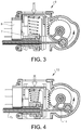
- Fig. 3 shows the door opener in the first pushed-in position
- Fig. 4 shows the door opener in the second pushed-in position.
- the door opener 1 comprises a push button 2 having a front surface 3 and side walls 4.
- the front surface 3 is adapted to be operated by a user and is thus preferably designed in a shape that is pleasant to touch and that is smooth.
- the front surface may be flat or slightly curved, and may comprise a symbol showing the function of the push button, i.e. that it is a door opener button.
- the symbol may be moulded in a two component moulding procedure and may be back lit with a light source.
- the shape is preferably rectangular, but other shapes are also plausible.
- the shape of the push button may be rectangular with the long side being at least 25 mm and the short side being at least 15 mm, such that the push button can easily be operated by a finger of a user.
- the shape of the push button may also be circular with a diameter of 20 mm or more. Other shapes are also possible. It is important that the user can push the push button to the second pushed-in position with a finger. However, the fit to a finger may be relatively tight since the second pushed-in position will not be used very often.
- the body 6 of the door opener preferably encloses the components of the door opener such that the door opener can be handled as a stand-alone component without damaging any of the included components.
- the body may thus be formed in e.g. a box-shape comprising attachment means such that the door opener can be mounted to a trim panel in an easy way and such that it easily can be removed if it needs to be replaced.
- the body is in the shown example provided with a position member 20 which is somewhat resilient and which is provided with an inward protrusion. A lower edge of the push button will interact with the position member when the push button is pushed past the first pushed-in position. In this way, a user will detect when the first pushed-in position is reached and when the move to the second pushed-in position starts.
- the side walls 4 of the push button are preferably parallel.
- the side walls may be provided with guiding means, such as one or more ridges, which are adapted to interact with corresponding grooves 5 in the body 6 of the door opener.
- the guiding means ensures that the push button will travel in a predictable manner and that the push button will spring back when it is released by a user.
- a side wall of the push button is further provided with an interaction section 7 adapted to interact with the actuator of a switch element 8, e.g. a micro switch, when the push button is in the first pushed-in position 9. It is also possible to use other types of position detecting means, such as other types of electrical contacts or optical position detection means, such as an optical fork coupler.
- a micro switch is however suitable since it is reliable, has a snap action contact element and is weather sealed, which is of advantage when the switch is positioned behind the interior panel, towards the outside of the door. It is also possible to drive an electric actuator, e.g. a solenoid, directly through a micro switch in order to open the door latch.
- an electric actuator e.g. a solenoid
- the shown push button is further provided with teeth 11 on one side wall 4.
- the teeth are adapted to interact with a toothed wheel 12 which constitutes a transmission 13.
- the purpose of the transmission is to transfer the pushing action of the push button to a pulling action that will be able to pull the inner wire 14 of the Bowden cable 15.
- the pushing action of the push button will be transferred to a perpendicular pulling action, but other pulling directions are of course also possible, depending on the positions of the door opener and the door lock of the door.
- the wire 14 is attached to the toothed wheel 12 and the Bowden cable is attached to a mounting socket 16 of the door opener body 6.
- the push button is in an idle position 18.
- the front surface 3 of the push button is in this example flush with the bezel of the door opener. In another example, the front surface 3 protrudes by e.g. 1 mm from the surface of the bezel 17.
- the door opener is shown in the first pushed-in position 9. In this position, the interaction section 7 of the push button body 4 interacts with the actuator of the micro switch 8, and pushes it inwards.
- the micro switch will in this position give a signal to an electric actuator, e.g. a solenoid or an electric motor, such that the door latch can be released.
- the signal may be directly connected to the electric actuator or may be routed through an electronic control unit.
- a release signal By sending a release signal to an electronic control unit, it is possible to apply further rules in order to control the release of the door latch, i.e. to control the opening of the door.
- One such rule may be the speed of the vehicle. It may e.g. be possible to prevent the release of the door latch if the vehicle is moving faster than 5 km/h, or if the vehicle is reversing. This will further ensure that the door is not opened erroneously.
- Fig. 4 shows the push button in the second pushed-in position 10.
- the push button is pushed to its lowermost position.
- the teeth 11 has caused the toothed wheel 12 to rotate counter-clockwise such that the wire 14 of the Bowden cable is pulled to its release position, in which the door latch is released.
- this second pushed-in position overrides other lock functions of the door lock, such that the door latch is always released when the push button is in the second pushed-in position 10. It is also possible to prevent the release of the latch in the second pushed-in position if there is power available in the vehicle, e.g. if the vehicle is travelling with a certain speed.
Landscapes
- Lock And Its Accessories (AREA)
Abstract
Description
- The present invention relates to a combined electrical and mechanical door opener adapted to be used as an inner door opener in a vehicle. By using a door opener comprising both an electrical switch and a mechanical actuating means, a simple and cost-effective door opener is provided, which is easy to install and which requires less space than a conventional door lever.
- Most modern cars are provided with a central lock function, in which every door lock is provided with an electrical actuator that operates the lock mechanism. The central lock is operated by the use of a remote control, which sends an open or close signal to the vehicle control unit. Some cars are also provided with a keyless entry system, in which a key comprising a transmitter is recognized by the vehicle control unit when it is in the close proximity of the vehicle.
- A door of the vehicle can then be opened without the need of using a remote control or by using a car key. When a driver and possible one or more passengers are seated in the car and the car engine is started, some manufacturers have implemented an automatic car lock function, which locks the doors after a few minutes. This is seen as a security function intended to avoid carjacking or preventing someone from opening a door from the outside, e.g. at a red light.
- When a door is closed or locked, it is possible to open it from the inside. A door is provided with a door handle or door lever in the interior door panel, which comprises a mechanical connection to the door lock such that the lock mechanism can be unlatched from the inside when the lock is either closed or locked. The mechanical connection also allows a door to be opened from the inside even if the car would be without electricity, e.g. if the battery is empty or if the electrical actuator at the rear door is broken. Some cars may also be provided with an electrical switch in the handle that will open the door with just a touch of the switch, such that the handle must not be operated in normal conditions, i.e. when the vehicle has electric power. If the battery is empty, the handle must be pulled in order to activate a mechanical latch of the lock. Alternatively, a key may be rotated in order to open the door.
-
EP 1162332 B1 discloses a handle for a vehicle door, arranged on the outside of the vehicle door. An inner lateral surface facing the door is provided with a first push-button actuating device for electrically controlling a lock on the door, and a second mechanical push-button actuating device. The second mechanical actuating device is provided with a trigger-type actuating member, who extends through an opening formed in the inner surface, and is movable between an extracted rest position extending partly outwards of the inner surface, and a withdrawn control position inserted inside the handle. The second mechanical actuating device cooperates with a lever forming part of a mechanical actuating device for activating the door lock. - It is also possible to provide an inner door handle or door grip with an electrical switch in order to be able to open a door in an easy way, without having to pull the handle. In some cases, a handle or a grip may be relatively large and may be difficult to design into the interior door panel in an aesthetic satisfactory manner. Further, it may be difficult to provide a mechanical lever to operate the lock, especially if there are several different car models using the same lock arrangement.
- There is thus room for an improved inner door opener for a door lock in a vehicle door.
- An object of the invention is therefore to provide an improved inner door opener for a vehicle. A further object of the invention is to provide a vehicle comprising such an interior trim panel.
- The solution to the problem according to the invention is described in the characterizing part of claim 1 regarding the inner door opener and in
claim 14 regarding the vehicle. The other claims contain advantageous further developments of the inner door opener. - In an inner door opener for a vehicle, comprising a spring-loaded push button with a front surface, where the push button is adapted to close an electric circuit in a first pushed-in position, the object of the invention is achieved in that the push button is adapted to release a door lock latch through a Bowden cable in a second pushed-in position.
- By this first embodiment of an inner door opener according to the invention, a spring-loaded push button adapted to be used in an interior trim panel of a car is provided. The push button is provided with a first pushed-in position in which an electrical circuit is closed, such that an electric actuator can release a latch in a door lock. The operating button is further provided with a second pushed-in position in which a wire in a Bowden cable is operated, such that the latch of the door lock can be released mechanically. In this way, a simple and convenient way of opening the door is provided. The door opener is further relatively small and can easily be designed into an interior panel of a vehicle. At the same time, an emergency opening of the door is provided, in which the push button can release the latch of the door lock when no electricity is available for the electrical actuator. The push button can release the latch when the door lock is closed and when it is locked.
- The push button is spring-loaded and is pushed in a linear movement. The front surface of the push button may be flush with the bezel of the door opener, or may protrude some from the bezel when the push button is in an idle position. In one example, the front surface of the push button protrudes from the bezel by 1 mm in the idle position and the stroke to the first pushed-in position is 2 mm, such that the front surface of the push button is 1 mm lower than the bezel when the push button is in the first pushed-in position. This will give a pleasant appearance of the push button in the bezel, and ensures that the front surface must be pushed pass the surface of the bezel in order to open the door. An elbow or the like will thus not be able to open the door accidentally.
- A micro switch is preferably used as the switch element that closes the electric circuit. It is also possible to use e.g. an optical fork coupler or another type of electrical contact. A micro switch is however reliable and weather proof.
- The second pushed-in position is reached when the push button is pushed further into the door opener. The stroke to reach the second pushed-in position is preferably in the range between 13 - 20 mm from the idle position. When the first pushed-in position is reached and the push button is pushed further, the push button will pull an inner wire of a Bowden cable which is mechanically attached to the release latch of the door lock. When the second pushed-in position is reached, the latch will be released and the door will be opened. By using a Bowden cable, the installation of the door opener is simplified and it is possible to use the same door opener in different car models without exchanging any parts.
- The inner wire of the Bowden cable may be attached directly to the push button, but it may be difficult to obtain a pulling action of the Bowden cable in an easy way by a direct attachment of the Bowden cable. It is thus preferred to use a transmission between the push button and the wire of the Bowden cable. In on example, the transmission comprises a toothed wheel which interacts with teeth of the push button. It is also possible to let the transmission be a lever that is pushed by the push button, where the lever is pivotally arranged and which pulls the wire of the Bowden cable on the other side of the pivot axle. A suitable travel distance for the wire of the Bowden cable to release the latch is between 10 - 20 mm. This is also a suitable stroke distance for the push button, in order to release a latch mechanically in an emergency situation. The ratio of the transmission may thus preferably be in the region of 1:1, even if it is also possible to use other ratios.
- The invention will be described in greater detail in the following, with reference to the attached drawings, in which
- Fig. 1
- shows an example of a door opener according to the invention in an idle position,
- Fig. 2
- shows a split view of a door opener according to the invention in an idle position,
- Fig. 3
- shows a split view a door opener according to the invention in a first pushed-in position, and
- Fig. 4
- shows a split view of a door opener according to the invention in a second pushed-in position.
- The embodiments of the invention with further developments described in the following are to be regarded only as examples and are in no way to limit the scope of the protection provided by the patent claims.
-
Fig. 1 and Fig. 2 shows a first example of a door opener according to the invention in the idle position,Fig. 3 shows the door opener in the first pushed-in position, andFig. 4 shows the door opener in the second pushed-in position. The door opener 1 comprises apush button 2 having afront surface 3 andside walls 4. Thefront surface 3 is adapted to be operated by a user and is thus preferably designed in a shape that is pleasant to touch and that is smooth. The front surface may be flat or slightly curved, and may comprise a symbol showing the function of the push button, i.e. that it is a door opener button. The symbol may be moulded in a two component moulding procedure and may be back lit with a light source. The shape is preferably rectangular, but other shapes are also plausible. The shape of the push button may be rectangular with the long side being at least 25 mm and the short side being at least 15 mm, such that the push button can easily be operated by a finger of a user. The shape of the push button may also be circular with a diameter of 20 mm or more. Other shapes are also possible. It is important that the user can push the push button to the second pushed-in position with a finger. However, the fit to a finger may be relatively tight since the second pushed-in position will not be used very often. - The body 6 of the door opener preferably encloses the components of the door opener such that the door opener can be handled as a stand-alone component without damaging any of the included components. The body may thus be formed in e.g. a box-shape comprising attachment means such that the door opener can be mounted to a trim panel in an easy way and such that it easily can be removed if it needs to be replaced. The body is in the shown example provided with a
position member 20 which is somewhat resilient and which is provided with an inward protrusion. A lower edge of the push button will interact with the position member when the push button is pushed past the first pushed-in position. In this way, a user will detect when the first pushed-in position is reached and when the move to the second pushed-in position starts. - The
side walls 4 of the push button are preferably parallel. The side walls may be provided with guiding means, such as one or more ridges, which are adapted to interact withcorresponding grooves 5 in the body 6 of the door opener. The guiding means ensures that the push button will travel in a predictable manner and that the push button will spring back when it is released by a user. A side wall of the push button is further provided with aninteraction section 7 adapted to interact with the actuator of aswitch element 8, e.g. a micro switch, when the push button is in the first pushed-inposition 9. It is also possible to use other types of position detecting means, such as other types of electrical contacts or optical position detection means, such as an optical fork coupler. A micro switch is however suitable since it is reliable, has a snap action contact element and is weather sealed, which is of advantage when the switch is positioned behind the interior panel, towards the outside of the door. It is also possible to drive an electric actuator, e.g. a solenoid, directly through a micro switch in order to open the door latch. - The shown push button is further provided with
teeth 11 on oneside wall 4. The teeth are adapted to interact with atoothed wheel 12 which constitutes atransmission 13. The purpose of the transmission is to transfer the pushing action of the push button to a pulling action that will be able to pull theinner wire 14 of theBowden cable 15. In the shown example, the pushing action of the push button will be transferred to a perpendicular pulling action, but other pulling directions are of course also possible, depending on the positions of the door opener and the door lock of the door. Thewire 14 is attached to thetoothed wheel 12 and the Bowden cable is attached to a mounting socket 16 of the door opener body 6. - In
Fig. 2 , the push button is in anidle position 18. Thefront surface 3 of the push button is in this example flush with the bezel of the door opener. In another example, thefront surface 3 protrudes by e.g. 1 mm from the surface of thebezel 17. InFig. 3 , the door opener is shown in the first pushed-inposition 9. In this position, theinteraction section 7 of thepush button body 4 interacts with the actuator of themicro switch 8, and pushes it inwards. The micro switch will in this position give a signal to an electric actuator, e.g. a solenoid or an electric motor, such that the door latch can be released. The signal may be directly connected to the electric actuator or may be routed through an electronic control unit. By sending a release signal to an electronic control unit, it is possible to apply further rules in order to control the release of the door latch, i.e. to control the opening of the door. One such rule may be the speed of the vehicle. It may e.g. be possible to prevent the release of the door latch if the vehicle is moving faster than 5 km/h, or if the vehicle is reversing. This will further ensure that the door is not opened erroneously. -
Fig. 4 shows the push button in the second pushed-inposition 10. In this position, the push button is pushed to its lowermost position. Theteeth 11 has caused thetoothed wheel 12 to rotate counter-clockwise such that thewire 14 of the Bowden cable is pulled to its release position, in which the door latch is released. Preferably, this second pushed-in position overrides other lock functions of the door lock, such that the door latch is always released when the push button is in the second pushed-inposition 10. It is also possible to prevent the release of the latch in the second pushed-in position if there is power available in the vehicle, e.g. if the vehicle is travelling with a certain speed. - The invention is not to be regarded as being limited to the embodiments described above, a number of additional variants and modifications being possible within the scope of the subsequent patent claims.
-
- 1:
- Door opener
- 2:
- Push button
- 3:
- Front surface
- 4:
- Side wall
- 5:
- Groove
- 6:
- Door opener body
- 7:
- Interaction section
- 8:
- Micro switch
- 9:
- First pushed-in position
- 10:
- Second pushed-in position
- 11:
- Teeth
- 12:
- Toothed wheel
- 13:
- Transmission
- 14:
- Wire
- 15:
- Bowden cable
- 16:
- Mounting socket
- 17:
- Bezel
- 18:
- Idle position
- 19:
- Coil spring
- 20:
- Position member
Claims (14)
- Inner door opener (1) for a vehicle, comprising a spring-loaded push button (2) with a front surface (3), where the push button (2) is adapted to close an electric circuit in a first pushed-in position (9), characterized in that the push button (2) is adapted to release a door lock latch through a Bowden cable (15) in a second pushed-in position (10).
- Door opener according to claim 1, characterized in that the door opener (1) comprises a micro switch (8) for the closing of the electric circuit.
- Door opener according to claim 1 or 2, characterized in that the stroke from an idle position (18) to the first pushed-in position (9) is in the range of 1 - 4 mm.
- Door opener according to any of the preceding claims, characterized in that the stroke from an idle position (18) to the second pushed-in position (10) is in the range of 13 - 20 mm.
- Door opener according to any of the preceding claims, characterized in that the push button (2) will return to the idle position (18) by the use of a coil spring (19).
- Door opener according to any of the preceding claims, characterized in that the push button (2) is attached directly to the wire (14) of the Bowden cable (15).
- Door opener according to any of claims 1 to 5, characterized in that the push button (2) is attached to the wire (14) of the Bowden cable (15) through a transmission element (13).
- Door opener according claim 7, characterized in that the transmission element (13) is a toothed wheel (12).
- Door opener according claim 7, characterized in that the transmission element (13) is a lever.
- Door opener according to any of claims 7 to 9, characterized in that the ratio of the transmission element (13) is 1:1.
- Door opener according to any of the preceding claims, characterized in that the front surface (3) of the push button (2) is flush with the bezel (17) of the door opener when the push button (2) is in the idle position (18).
- Door opener according to any of claims 1 to 10, characterized in that the front surface (3) of the push button (2) protrudes from the bezel (17) of the door opener when the push button (2) is in the idle position (18).
- Door opener according to any of the preceding claims, characterized in that the front surface (3) of the push button (2) extends inwards from the bezel (17) of the door opener when the push button (2) is in the first pushed-in position (9).
- Vehicle, comprising a door opener according to any of claims 1 to 13.
Priority Applications (1)
| Application Number | Priority Date | Filing Date | Title |
|---|---|---|---|
| EP16169830.3A EP3246498B1 (en) | 2016-05-17 | 2016-05-17 | Combined electrical and mechanical door opener |
Applications Claiming Priority (1)
| Application Number | Priority Date | Filing Date | Title |
|---|---|---|---|
| EP16169830.3A EP3246498B1 (en) | 2016-05-17 | 2016-05-17 | Combined electrical and mechanical door opener |
Publications (2)
| Publication Number | Publication Date |
|---|---|
| EP3246498A1 true EP3246498A1 (en) | 2017-11-22 |
| EP3246498B1 EP3246498B1 (en) | 2019-11-27 |
Family
ID=56024118
Family Applications (1)
| Application Number | Title | Priority Date | Filing Date |
|---|---|---|---|
| EP16169830.3A Active EP3246498B1 (en) | 2016-05-17 | 2016-05-17 | Combined electrical and mechanical door opener |
Country Status (1)
| Country | Link |
|---|---|
| EP (1) | EP3246498B1 (en) |
Cited By (9)
| Publication number | Priority date | Publication date | Assignee | Title |
|---|---|---|---|---|
| CN108720782A (en) * | 2018-06-07 | 2018-11-02 | 温州天健电器有限公司 | A kind of dish-washing machine door lock |
| WO2019120598A1 (en) * | 2017-12-22 | 2019-06-27 | Huf Hülsbeck & Fürst Gmbh & Co. Kg | Motor vehicle door handle arrangement with an operating module |
| DE102018108999A1 (en) * | 2018-04-16 | 2019-10-17 | Lisa Dräxlmaier GmbH | OPERATING UNIT FOR OPENING A LOCK TRAP OF A DOOR AND / OR FLAP OF A MOTOR VEHICLE |
| WO2019207220A1 (en) | 2018-04-23 | 2019-10-31 | Psa Automobiles Sa | Electrical control for opening door from the inside also comprising mechanical means |
| DE102018210422A1 (en) * | 2018-06-26 | 2020-01-02 | Witte Automotive Gmbh | Handle arrangement for a door lock |
| CN112554672A (en) * | 2019-09-26 | 2021-03-26 | 利萨·德雷克塞迈尔有限责任公司 | Emergency operating device for manually opening a vehicle door |
| US20220145673A1 (en) * | 2019-04-08 | 2022-05-12 | Trimark Europe Limited | A Remotely Operable Push Button Lock Mechanism |
| CN114776151A (en) * | 2022-03-22 | 2022-07-22 | 神通科技集团股份有限公司 | Push type vehicle internal open switch |
| WO2025184009A1 (en) * | 2024-02-29 | 2025-09-04 | Mullen Technologies, Inc. | Multifunction switch |
Citations (6)
| Publication number | Priority date | Publication date | Assignee | Title |
|---|---|---|---|---|
| DE3307541A1 (en) * | 1983-03-03 | 1984-09-06 | Paul Stoessel GmbH + Co KG, 4005 Meerbusch | Adjusting device, for example for a throttle flap |
| DE20114838U1 (en) * | 2001-09-08 | 2001-12-13 | Drumm GmbH, 97337 Dettelbach | Generator drive for electrical or electronic locking systems |
| EP1455039A2 (en) * | 2003-03-06 | 2004-09-08 | Huf Hülsbeck & Fürst GmbH & Co. KG | Device for motor actuation and emergency device for manual action of a lock for lids or doors of a vehicle, in particular for a glove compartment |
| EP1162332B1 (en) | 2000-06-09 | 2004-09-08 | FIAT AUTO S.p.A. | Vehicle door handle |
| US20060005589A1 (en) * | 2004-07-06 | 2006-01-12 | Honda Motor Co., Ltd. | Push-button box-opening structure |
| DE102004049435A1 (en) * | 2004-10-08 | 2006-04-13 | Zf Friedrichshafen Ag | Button with cable |
-
2016
- 2016-05-17 EP EP16169830.3A patent/EP3246498B1/en active Active
Patent Citations (6)
| Publication number | Priority date | Publication date | Assignee | Title |
|---|---|---|---|---|
| DE3307541A1 (en) * | 1983-03-03 | 1984-09-06 | Paul Stoessel GmbH + Co KG, 4005 Meerbusch | Adjusting device, for example for a throttle flap |
| EP1162332B1 (en) | 2000-06-09 | 2004-09-08 | FIAT AUTO S.p.A. | Vehicle door handle |
| DE20114838U1 (en) * | 2001-09-08 | 2001-12-13 | Drumm GmbH, 97337 Dettelbach | Generator drive for electrical or electronic locking systems |
| EP1455039A2 (en) * | 2003-03-06 | 2004-09-08 | Huf Hülsbeck & Fürst GmbH & Co. KG | Device for motor actuation and emergency device for manual action of a lock for lids or doors of a vehicle, in particular for a glove compartment |
| US20060005589A1 (en) * | 2004-07-06 | 2006-01-12 | Honda Motor Co., Ltd. | Push-button box-opening structure |
| DE102004049435A1 (en) * | 2004-10-08 | 2006-04-13 | Zf Friedrichshafen Ag | Button with cable |
Cited By (11)
| Publication number | Priority date | Publication date | Assignee | Title |
|---|---|---|---|---|
| WO2019120598A1 (en) * | 2017-12-22 | 2019-06-27 | Huf Hülsbeck & Fürst Gmbh & Co. Kg | Motor vehicle door handle arrangement with an operating module |
| DE102018108999A1 (en) * | 2018-04-16 | 2019-10-17 | Lisa Dräxlmaier GmbH | OPERATING UNIT FOR OPENING A LOCK TRAP OF A DOOR AND / OR FLAP OF A MOTOR VEHICLE |
| WO2019207220A1 (en) | 2018-04-23 | 2019-10-31 | Psa Automobiles Sa | Electrical control for opening door from the inside also comprising mechanical means |
| CN108720782A (en) * | 2018-06-07 | 2018-11-02 | 温州天健电器有限公司 | A kind of dish-washing machine door lock |
| DE102018210422A1 (en) * | 2018-06-26 | 2020-01-02 | Witte Automotive Gmbh | Handle arrangement for a door lock |
| US20220145673A1 (en) * | 2019-04-08 | 2022-05-12 | Trimark Europe Limited | A Remotely Operable Push Button Lock Mechanism |
| CN112554672A (en) * | 2019-09-26 | 2021-03-26 | 利萨·德雷克塞迈尔有限责任公司 | Emergency operating device for manually opening a vehicle door |
| EP3798393A1 (en) * | 2019-09-26 | 2021-03-31 | Lisa Dräxlmaier GmbH | Emergency operating device for manually opening a vehicle door |
| CN112554672B (en) * | 2019-09-26 | 2022-02-01 | 利萨·德雷克塞迈尔有限责任公司 | Emergency operating device for manually opening a vehicle door |
| CN114776151A (en) * | 2022-03-22 | 2022-07-22 | 神通科技集团股份有限公司 | Push type vehicle internal open switch |
| WO2025184009A1 (en) * | 2024-02-29 | 2025-09-04 | Mullen Technologies, Inc. | Multifunction switch |
Also Published As
| Publication number | Publication date |
|---|---|
| EP3246498B1 (en) | 2019-11-27 |
Similar Documents
| Publication | Publication Date | Title |
|---|---|---|
| EP3246498B1 (en) | Combined electrical and mechanical door opener | |
| CN101666192B (en) | Latch system for a door of an automobile | |
| US10563437B2 (en) | Flush comfort handle | |
| CN102575487B (en) | Handle device | |
| CN106256982B (en) | Handle for vehicle door | |
| US11174663B2 (en) | Exterior door handle arrangement for a motor vehicle | |
| US10590681B2 (en) | Door latch system | |
| US8613160B2 (en) | Door opening and closing apparatus for vehicle | |
| US10995526B2 (en) | Door latch system | |
| CN103608540B (en) | Closing mechanism for vehicle doors | |
| US20140047877A1 (en) | Door handle assembly for a vehicle | |
| CN116876930B (en) | Electric suction locking device, motor vehicle lock and motor vehicle | |
| US8833813B2 (en) | Handle device | |
| WO2019147757A1 (en) | Flush door handle assembly | |
| JP2016023460A (en) | Door latch device for vehicle | |
| US11859417B2 (en) | Locking device for car doors | |
| US9145717B2 (en) | Locking system for a motor vehicle door | |
| US20240076915A1 (en) | Vehicular closure opening device with push to actuate function | |
| US12104414B2 (en) | Unlocking device for unlocking a lock of a movable vehicle element and vehicle | |
| KR101929454B1 (en) | Button-type door open device | |
| CN111344468B (en) | motor vehicle lock | |
| JP2013133640A (en) | Lock system with detection function of opening/closing body for vehicle | |
| US9127488B2 (en) | Method for assembling a handle in an openable body section of an automobile and associated openable body section handle | |
| GB2406608A (en) | Vehicle lock assembly with speed sensitive switch | |
| US11952809B2 (en) | Actuating device for a lock of a vehicle, and vehicle door and vehicle having said vehicle door |
Legal Events
| Date | Code | Title | Description |
|---|---|---|---|
| PUAI | Public reference made under article 153(3) epc to a published international application that has entered the european phase |
Free format text: ORIGINAL CODE: 0009012 |
|
| STAA | Information on the status of an ep patent application or granted ep patent |
Free format text: STATUS: THE APPLICATION HAS BEEN PUBLISHED |
|
| AK | Designated contracting states |
Kind code of ref document: A1 Designated state(s): AL AT BE BG CH CY CZ DE DK EE ES FI FR GB GR HR HU IE IS IT LI LT LU LV MC MK MT NL NO PL PT RO RS SE SI SK SM TR |
|
| AX | Request for extension of the european patent |
Extension state: BA ME |
|
| STAA | Information on the status of an ep patent application or granted ep patent |
Free format text: STATUS: REQUEST FOR EXAMINATION WAS MADE |
|
| 17P | Request for examination filed |
Effective date: 20180522 |
|
| RBV | Designated contracting states (corrected) |
Designated state(s): AL AT BE BG CH CY CZ DE DK EE ES FI FR GB GR HR HU IE IS IT LI LT LU LV MC MK MT NL NO PL PT RO RS SE SI SK SM TR |
|
| RIC1 | Information provided on ipc code assigned before grant |
Ipc: E05B 85/12 20140101ALI20190716BHEP Ipc: E05B 81/76 20140101ALI20190716BHEP Ipc: E05B 1/00 20060101ALI20190716BHEP Ipc: E05B 17/10 20060101ALN20190716BHEP Ipc: E05B 77/54 20140101ALN20190716BHEP Ipc: E05B 81/90 20140101AFI20190716BHEP Ipc: E05B 39/00 20060101ALN20190716BHEP Ipc: E05B 79/20 20140101ALI20190716BHEP |
|
| GRAP | Despatch of communication of intention to grant a patent |
Free format text: ORIGINAL CODE: EPIDOSNIGR1 |
|
| STAA | Information on the status of an ep patent application or granted ep patent |
Free format text: STATUS: GRANT OF PATENT IS INTENDED |
|
| INTG | Intention to grant announced |
Effective date: 20190903 |
|
| GRAS | Grant fee paid |
Free format text: ORIGINAL CODE: EPIDOSNIGR3 |
|
| GRAA | (expected) grant |
Free format text: ORIGINAL CODE: 0009210 |
|
| STAA | Information on the status of an ep patent application or granted ep patent |
Free format text: STATUS: THE PATENT HAS BEEN GRANTED |
|
| AK | Designated contracting states |
Kind code of ref document: B1 Designated state(s): AL AT BE BG CH CY CZ DE DK EE ES FI FR GB GR HR HU IE IS IT LI LT LU LV MC MK MT NL NO PL PT RO RS SE SI SK SM TR |
|
| REG | Reference to a national code |
Ref country code: GB Ref legal event code: FG4D |
|
| REG | Reference to a national code |
Ref country code: CH Ref legal event code: EP |
|
| REG | Reference to a national code |
Ref country code: AT Ref legal event code: REF Ref document number: 1206832 Country of ref document: AT Kind code of ref document: T Effective date: 20191215 |
|
| REG | Reference to a national code |
Ref country code: DE Ref legal event code: R096 Ref document number: 602016024932 Country of ref document: DE |
|
| REG | Reference to a national code |
Ref country code: IE Ref legal event code: FG4D |
|
| REG | Reference to a national code |
Ref country code: NL Ref legal event code: MP Effective date: 20191127 |
|
| REG | Reference to a national code |
Ref country code: LT Ref legal event code: MG4D |
|
| PG25 | Lapsed in a contracting state [announced via postgrant information from national office to epo] |
Ref country code: GR Free format text: LAPSE BECAUSE OF FAILURE TO SUBMIT A TRANSLATION OF THE DESCRIPTION OR TO PAY THE FEE WITHIN THE PRESCRIBED TIME-LIMIT Effective date: 20200228 Ref country code: LT Free format text: LAPSE BECAUSE OF FAILURE TO SUBMIT A TRANSLATION OF THE DESCRIPTION OR TO PAY THE FEE WITHIN THE PRESCRIBED TIME-LIMIT Effective date: 20191127 Ref country code: NL Free format text: LAPSE BECAUSE OF FAILURE TO SUBMIT A TRANSLATION OF THE DESCRIPTION OR TO PAY THE FEE WITHIN THE PRESCRIBED TIME-LIMIT Effective date: 20191127 Ref country code: LV Free format text: LAPSE BECAUSE OF FAILURE TO SUBMIT A TRANSLATION OF THE DESCRIPTION OR TO PAY THE FEE WITHIN THE PRESCRIBED TIME-LIMIT Effective date: 20191127 Ref country code: SE Free format text: LAPSE BECAUSE OF FAILURE TO SUBMIT A TRANSLATION OF THE DESCRIPTION OR TO PAY THE FEE WITHIN THE PRESCRIBED TIME-LIMIT Effective date: 20191127 Ref country code: NO Free format text: LAPSE BECAUSE OF FAILURE TO SUBMIT A TRANSLATION OF THE DESCRIPTION OR TO PAY THE FEE WITHIN THE PRESCRIBED TIME-LIMIT Effective date: 20200227 Ref country code: FI Free format text: LAPSE BECAUSE OF FAILURE TO SUBMIT A TRANSLATION OF THE DESCRIPTION OR TO PAY THE FEE WITHIN THE PRESCRIBED TIME-LIMIT Effective date: 20191127 Ref country code: BG Free format text: LAPSE BECAUSE OF FAILURE TO SUBMIT A TRANSLATION OF THE DESCRIPTION OR TO PAY THE FEE WITHIN THE PRESCRIBED TIME-LIMIT Effective date: 20200227 |
|
| PG25 | Lapsed in a contracting state [announced via postgrant information from national office to epo] |
Ref country code: RS Free format text: LAPSE BECAUSE OF FAILURE TO SUBMIT A TRANSLATION OF THE DESCRIPTION OR TO PAY THE FEE WITHIN THE PRESCRIBED TIME-LIMIT Effective date: 20191127 Ref country code: IS Free format text: LAPSE BECAUSE OF FAILURE TO SUBMIT A TRANSLATION OF THE DESCRIPTION OR TO PAY THE FEE WITHIN THE PRESCRIBED TIME-LIMIT Effective date: 20200327 Ref country code: HR Free format text: LAPSE BECAUSE OF FAILURE TO SUBMIT A TRANSLATION OF THE DESCRIPTION OR TO PAY THE FEE WITHIN THE PRESCRIBED TIME-LIMIT Effective date: 20191127 |
|
| PG25 | Lapsed in a contracting state [announced via postgrant information from national office to epo] |
Ref country code: AL Free format text: LAPSE BECAUSE OF FAILURE TO SUBMIT A TRANSLATION OF THE DESCRIPTION OR TO PAY THE FEE WITHIN THE PRESCRIBED TIME-LIMIT Effective date: 20191127 |
|
| PG25 | Lapsed in a contracting state [announced via postgrant information from national office to epo] |
Ref country code: EE Free format text: LAPSE BECAUSE OF FAILURE TO SUBMIT A TRANSLATION OF THE DESCRIPTION OR TO PAY THE FEE WITHIN THE PRESCRIBED TIME-LIMIT Effective date: 20191127 Ref country code: PT Free format text: LAPSE BECAUSE OF FAILURE TO SUBMIT A TRANSLATION OF THE DESCRIPTION OR TO PAY THE FEE WITHIN THE PRESCRIBED TIME-LIMIT Effective date: 20200419 Ref country code: DK Free format text: LAPSE BECAUSE OF FAILURE TO SUBMIT A TRANSLATION OF THE DESCRIPTION OR TO PAY THE FEE WITHIN THE PRESCRIBED TIME-LIMIT Effective date: 20191127 Ref country code: ES Free format text: LAPSE BECAUSE OF FAILURE TO SUBMIT A TRANSLATION OF THE DESCRIPTION OR TO PAY THE FEE WITHIN THE PRESCRIBED TIME-LIMIT Effective date: 20191127 Ref country code: CZ Free format text: LAPSE BECAUSE OF FAILURE TO SUBMIT A TRANSLATION OF THE DESCRIPTION OR TO PAY THE FEE WITHIN THE PRESCRIBED TIME-LIMIT Effective date: 20191127 Ref country code: RO Free format text: LAPSE BECAUSE OF FAILURE TO SUBMIT A TRANSLATION OF THE DESCRIPTION OR TO PAY THE FEE WITHIN THE PRESCRIBED TIME-LIMIT Effective date: 20191127 |
|
| REG | Reference to a national code |
Ref country code: DE Ref legal event code: R097 Ref document number: 602016024932 Country of ref document: DE |
|
| PG25 | Lapsed in a contracting state [announced via postgrant information from national office to epo] |
Ref country code: SM Free format text: LAPSE BECAUSE OF FAILURE TO SUBMIT A TRANSLATION OF THE DESCRIPTION OR TO PAY THE FEE WITHIN THE PRESCRIBED TIME-LIMIT Effective date: 20191127 Ref country code: SK Free format text: LAPSE BECAUSE OF FAILURE TO SUBMIT A TRANSLATION OF THE DESCRIPTION OR TO PAY THE FEE WITHIN THE PRESCRIBED TIME-LIMIT Effective date: 20191127 |
|
| REG | Reference to a national code |
Ref country code: AT Ref legal event code: MK05 Ref document number: 1206832 Country of ref document: AT Kind code of ref document: T Effective date: 20191127 |
|
| PLBE | No opposition filed within time limit |
Free format text: ORIGINAL CODE: 0009261 |
|
| STAA | Information on the status of an ep patent application or granted ep patent |
Free format text: STATUS: NO OPPOSITION FILED WITHIN TIME LIMIT |
|
| 26N | No opposition filed |
Effective date: 20200828 |
|
| PG25 | Lapsed in a contracting state [announced via postgrant information from national office to epo] |
Ref country code: PL Free format text: LAPSE BECAUSE OF FAILURE TO SUBMIT A TRANSLATION OF THE DESCRIPTION OR TO PAY THE FEE WITHIN THE PRESCRIBED TIME-LIMIT Effective date: 20191127 Ref country code: SI Free format text: LAPSE BECAUSE OF FAILURE TO SUBMIT A TRANSLATION OF THE DESCRIPTION OR TO PAY THE FEE WITHIN THE PRESCRIBED TIME-LIMIT Effective date: 20191127 Ref country code: AT Free format text: LAPSE BECAUSE OF FAILURE TO SUBMIT A TRANSLATION OF THE DESCRIPTION OR TO PAY THE FEE WITHIN THE PRESCRIBED TIME-LIMIT Effective date: 20191127 |
|
| PG25 | Lapsed in a contracting state [announced via postgrant information from national office to epo] |
Ref country code: CH Free format text: LAPSE BECAUSE OF NON-PAYMENT OF DUE FEES Effective date: 20200531 Ref country code: MC Free format text: LAPSE BECAUSE OF FAILURE TO SUBMIT A TRANSLATION OF THE DESCRIPTION OR TO PAY THE FEE WITHIN THE PRESCRIBED TIME-LIMIT Effective date: 20191127 Ref country code: LI Free format text: LAPSE BECAUSE OF NON-PAYMENT OF DUE FEES Effective date: 20200531 |
|
| REG | Reference to a national code |
Ref country code: BE Ref legal event code: MM Effective date: 20200531 |
|
| GBPC | Gb: european patent ceased through non-payment of renewal fee |
Effective date: 20200517 |
|
| PG25 | Lapsed in a contracting state [announced via postgrant information from national office to epo] |
Ref country code: LU Free format text: LAPSE BECAUSE OF NON-PAYMENT OF DUE FEES Effective date: 20200517 |
|
| PG25 | Lapsed in a contracting state [announced via postgrant information from national office to epo] |
Ref country code: IE Free format text: LAPSE BECAUSE OF NON-PAYMENT OF DUE FEES Effective date: 20200517 Ref country code: GB Free format text: LAPSE BECAUSE OF NON-PAYMENT OF DUE FEES Effective date: 20200517 |
|
| PG25 | Lapsed in a contracting state [announced via postgrant information from national office to epo] |
Ref country code: BE Free format text: LAPSE BECAUSE OF NON-PAYMENT OF DUE FEES Effective date: 20200531 |
|
| PG25 | Lapsed in a contracting state [announced via postgrant information from national office to epo] |
Ref country code: TR Free format text: LAPSE BECAUSE OF FAILURE TO SUBMIT A TRANSLATION OF THE DESCRIPTION OR TO PAY THE FEE WITHIN THE PRESCRIBED TIME-LIMIT Effective date: 20191127 Ref country code: MT Free format text: LAPSE BECAUSE OF FAILURE TO SUBMIT A TRANSLATION OF THE DESCRIPTION OR TO PAY THE FEE WITHIN THE PRESCRIBED TIME-LIMIT Effective date: 20191127 Ref country code: CY Free format text: LAPSE BECAUSE OF FAILURE TO SUBMIT A TRANSLATION OF THE DESCRIPTION OR TO PAY THE FEE WITHIN THE PRESCRIBED TIME-LIMIT Effective date: 20191127 |
|
| PG25 | Lapsed in a contracting state [announced via postgrant information from national office to epo] |
Ref country code: MK Free format text: LAPSE BECAUSE OF FAILURE TO SUBMIT A TRANSLATION OF THE DESCRIPTION OR TO PAY THE FEE WITHIN THE PRESCRIBED TIME-LIMIT Effective date: 20191127 |
|
| P01 | Opt-out of the competence of the unified patent court (upc) registered |
Effective date: 20231212 |
|
| PGFP | Annual fee paid to national office [announced via postgrant information from national office to epo] |
Ref country code: DE Payment date: 20250423 Year of fee payment: 10 |
|
| PGFP | Annual fee paid to national office [announced via postgrant information from national office to epo] |
Ref country code: IT Payment date: 20250423 Year of fee payment: 10 |
|
| PGFP | Annual fee paid to national office [announced via postgrant information from national office to epo] |
Ref country code: FR Payment date: 20250423 Year of fee payment: 10 |