EP3246206A1 - Control device mounted on vehicle and method for controlling the vehicle - Google Patents
Control device mounted on vehicle and method for controlling the vehicle Download PDFInfo
- Publication number
- EP3246206A1 EP3246206A1 EP17169849.1A EP17169849A EP3246206A1 EP 3246206 A1 EP3246206 A1 EP 3246206A1 EP 17169849 A EP17169849 A EP 17169849A EP 3246206 A1 EP3246206 A1 EP 3246206A1
- Authority
- EP
- European Patent Office
- Prior art keywords
- vehicle
- light
- state
- road surface
- processor
- Prior art date
- Legal status (The legal status is an assumption and is not a legal conclusion. Google has not performed a legal analysis and makes no representation as to the accuracy of the status listed.)
- Withdrawn
Links
Images


Classifications
-
- B—PERFORMING OPERATIONS; TRANSPORTING
- B60—VEHICLES IN GENERAL
- B60Q—ARRANGEMENT OF SIGNALLING OR LIGHTING DEVICES, THE MOUNTING OR SUPPORTING THEREOF OR CIRCUITS THEREFOR, FOR VEHICLES IN GENERAL
- B60Q1/00—Arrangement of optical signalling or lighting devices, the mounting or supporting thereof or circuits therefor
- B60Q1/02—Arrangement of optical signalling or lighting devices, the mounting or supporting thereof or circuits therefor the devices being primarily intended to illuminate the way ahead or to illuminate other areas of way or environments
- B60Q1/04—Arrangement of optical signalling or lighting devices, the mounting or supporting thereof or circuits therefor the devices being primarily intended to illuminate the way ahead or to illuminate other areas of way or environments the devices being headlights
- B60Q1/06—Arrangement of optical signalling or lighting devices, the mounting or supporting thereof or circuits therefor the devices being primarily intended to illuminate the way ahead or to illuminate other areas of way or environments the devices being headlights adjustable, e.g. remotely-controlled from inside vehicle
- B60Q1/08—Arrangement of optical signalling or lighting devices, the mounting or supporting thereof or circuits therefor the devices being primarily intended to illuminate the way ahead or to illuminate other areas of way or environments the devices being headlights adjustable, e.g. remotely-controlled from inside vehicle automatically
- B60Q1/10—Arrangement of optical signalling or lighting devices, the mounting or supporting thereof or circuits therefor the devices being primarily intended to illuminate the way ahead or to illuminate other areas of way or environments the devices being headlights adjustable, e.g. remotely-controlled from inside vehicle automatically due to vehicle inclination, e.g. due to load distribution
-
- B—PERFORMING OPERATIONS; TRANSPORTING
- B60—VEHICLES IN GENERAL
- B60Q—ARRANGEMENT OF SIGNALLING OR LIGHTING DEVICES, THE MOUNTING OR SUPPORTING THEREOF OR CIRCUITS THEREFOR, FOR VEHICLES IN GENERAL
- B60Q1/00—Arrangement of optical signalling or lighting devices, the mounting or supporting thereof or circuits therefor
- B60Q1/02—Arrangement of optical signalling or lighting devices, the mounting or supporting thereof or circuits therefor the devices being primarily intended to illuminate the way ahead or to illuminate other areas of way or environments
- B60Q1/04—Arrangement of optical signalling or lighting devices, the mounting or supporting thereof or circuits therefor the devices being primarily intended to illuminate the way ahead or to illuminate other areas of way or environments the devices being headlights
- B60Q1/06—Arrangement of optical signalling or lighting devices, the mounting or supporting thereof or circuits therefor the devices being primarily intended to illuminate the way ahead or to illuminate other areas of way or environments the devices being headlights adjustable, e.g. remotely-controlled from inside vehicle
- B60Q1/08—Arrangement of optical signalling or lighting devices, the mounting or supporting thereof or circuits therefor the devices being primarily intended to illuminate the way ahead or to illuminate other areas of way or environments the devices being headlights adjustable, e.g. remotely-controlled from inside vehicle automatically
- B60Q1/085—Arrangement of optical signalling or lighting devices, the mounting or supporting thereof or circuits therefor the devices being primarily intended to illuminate the way ahead or to illuminate other areas of way or environments the devices being headlights adjustable, e.g. remotely-controlled from inside vehicle automatically due to special conditions, e.g. adverse weather, type of road, badly illuminated road signs or potential dangers
-
- B—PERFORMING OPERATIONS; TRANSPORTING
- B60—VEHICLES IN GENERAL
- B60Q—ARRANGEMENT OF SIGNALLING OR LIGHTING DEVICES, THE MOUNTING OR SUPPORTING THEREOF OR CIRCUITS THEREFOR, FOR VEHICLES IN GENERAL
- B60Q1/00—Arrangement of optical signalling or lighting devices, the mounting or supporting thereof or circuits therefor
- B60Q1/02—Arrangement of optical signalling or lighting devices, the mounting or supporting thereof or circuits therefor the devices being primarily intended to illuminate the way ahead or to illuminate other areas of way or environments
- B60Q1/04—Arrangement of optical signalling or lighting devices, the mounting or supporting thereof or circuits therefor the devices being primarily intended to illuminate the way ahead or to illuminate other areas of way or environments the devices being headlights
- B60Q1/06—Arrangement of optical signalling or lighting devices, the mounting or supporting thereof or circuits therefor the devices being primarily intended to illuminate the way ahead or to illuminate other areas of way or environments the devices being headlights adjustable, e.g. remotely-controlled from inside vehicle
- B60Q1/08—Arrangement of optical signalling or lighting devices, the mounting or supporting thereof or circuits therefor the devices being primarily intended to illuminate the way ahead or to illuminate other areas of way or environments the devices being headlights adjustable, e.g. remotely-controlled from inside vehicle automatically
- B60Q1/10—Arrangement of optical signalling or lighting devices, the mounting or supporting thereof or circuits therefor the devices being primarily intended to illuminate the way ahead or to illuminate other areas of way or environments the devices being headlights adjustable, e.g. remotely-controlled from inside vehicle automatically due to vehicle inclination, e.g. due to load distribution
- B60Q1/115—Arrangement of optical signalling or lighting devices, the mounting or supporting thereof or circuits therefor the devices being primarily intended to illuminate the way ahead or to illuminate other areas of way or environments the devices being headlights adjustable, e.g. remotely-controlled from inside vehicle automatically due to vehicle inclination, e.g. due to load distribution by electric means
-
- B—PERFORMING OPERATIONS; TRANSPORTING
- B60—VEHICLES IN GENERAL
- B60Q—ARRANGEMENT OF SIGNALLING OR LIGHTING DEVICES, THE MOUNTING OR SUPPORTING THEREOF OR CIRCUITS THEREFOR, FOR VEHICLES IN GENERAL
- B60Q1/00—Arrangement of optical signalling or lighting devices, the mounting or supporting thereof or circuits therefor
- B60Q1/02—Arrangement of optical signalling or lighting devices, the mounting or supporting thereof or circuits therefor the devices being primarily intended to illuminate the way ahead or to illuminate other areas of way or environments
- B60Q1/04—Arrangement of optical signalling or lighting devices, the mounting or supporting thereof or circuits therefor the devices being primarily intended to illuminate the way ahead or to illuminate other areas of way or environments the devices being headlights
- B60Q1/06—Arrangement of optical signalling or lighting devices, the mounting or supporting thereof or circuits therefor the devices being primarily intended to illuminate the way ahead or to illuminate other areas of way or environments the devices being headlights adjustable, e.g. remotely-controlled from inside vehicle
- B60Q1/08—Arrangement of optical signalling or lighting devices, the mounting or supporting thereof or circuits therefor the devices being primarily intended to illuminate the way ahead or to illuminate other areas of way or environments the devices being headlights adjustable, e.g. remotely-controlled from inside vehicle automatically
- B60Q1/12—Arrangement of optical signalling or lighting devices, the mounting or supporting thereof or circuits therefor the devices being primarily intended to illuminate the way ahead or to illuminate other areas of way or environments the devices being headlights adjustable, e.g. remotely-controlled from inside vehicle automatically due to steering position
-
- B—PERFORMING OPERATIONS; TRANSPORTING
- B60—VEHICLES IN GENERAL
- B60Q—ARRANGEMENT OF SIGNALLING OR LIGHTING DEVICES, THE MOUNTING OR SUPPORTING THEREOF OR CIRCUITS THEREFOR, FOR VEHICLES IN GENERAL
- B60Q1/00—Arrangement of optical signalling or lighting devices, the mounting or supporting thereof or circuits therefor
- B60Q1/02—Arrangement of optical signalling or lighting devices, the mounting or supporting thereof or circuits therefor the devices being primarily intended to illuminate the way ahead or to illuminate other areas of way or environments
- B60Q1/04—Arrangement of optical signalling or lighting devices, the mounting or supporting thereof or circuits therefor the devices being primarily intended to illuminate the way ahead or to illuminate other areas of way or environments the devices being headlights
- B60Q1/14—Arrangement of optical signalling or lighting devices, the mounting or supporting thereof or circuits therefor the devices being primarily intended to illuminate the way ahead or to illuminate other areas of way or environments the devices being headlights having dimming means
- B60Q1/1415—Dimming circuits
- B60Q1/1423—Automatic dimming circuits, i.e. switching between high beam and low beam due to change of ambient light or light level in road traffic
-
- B—PERFORMING OPERATIONS; TRANSPORTING
- B60—VEHICLES IN GENERAL
- B60Q—ARRANGEMENT OF SIGNALLING OR LIGHTING DEVICES, THE MOUNTING OR SUPPORTING THEREOF OR CIRCUITS THEREFOR, FOR VEHICLES IN GENERAL
- B60Q1/00—Arrangement of optical signalling or lighting devices, the mounting or supporting thereof or circuits therefor
- B60Q1/02—Arrangement of optical signalling or lighting devices, the mounting or supporting thereof or circuits therefor the devices being primarily intended to illuminate the way ahead or to illuminate other areas of way or environments
- B60Q1/24—Arrangement of optical signalling or lighting devices, the mounting or supporting thereof or circuits therefor the devices being primarily intended to illuminate the way ahead or to illuminate other areas of way or environments for lighting other areas than only the way ahead
-
- B—PERFORMING OPERATIONS; TRANSPORTING
- B60—VEHICLES IN GENERAL
- B60W—CONJOINT CONTROL OF VEHICLE SUB-UNITS OF DIFFERENT TYPE OR DIFFERENT FUNCTION; CONTROL SYSTEMS SPECIALLY ADAPTED FOR HYBRID VEHICLES; ROAD VEHICLE DRIVE CONTROL SYSTEMS FOR PURPOSES NOT RELATED TO THE CONTROL OF A PARTICULAR SUB-UNIT
- B60W40/00—Estimation or calculation of non-directly measurable driving parameters for road vehicle drive control systems not related to the control of a particular sub unit, e.g. by using mathematical models
- B60W40/02—Estimation or calculation of non-directly measurable driving parameters for road vehicle drive control systems not related to the control of a particular sub unit, e.g. by using mathematical models related to ambient conditions
- B60W40/06—Road conditions
-
- B—PERFORMING OPERATIONS; TRANSPORTING
- B60—VEHICLES IN GENERAL
- B60W—CONJOINT CONTROL OF VEHICLE SUB-UNITS OF DIFFERENT TYPE OR DIFFERENT FUNCTION; CONTROL SYSTEMS SPECIALLY ADAPTED FOR HYBRID VEHICLES; ROAD VEHICLE DRIVE CONTROL SYSTEMS FOR PURPOSES NOT RELATED TO THE CONTROL OF A PARTICULAR SUB-UNIT
- B60W40/00—Estimation or calculation of non-directly measurable driving parameters for road vehicle drive control systems not related to the control of a particular sub unit, e.g. by using mathematical models
- B60W40/10—Estimation or calculation of non-directly measurable driving parameters for road vehicle drive control systems not related to the control of a particular sub unit, e.g. by using mathematical models related to vehicle motion
- B60W40/105—Speed
-
- F—MECHANICAL ENGINEERING; LIGHTING; HEATING; WEAPONS; BLASTING
- F21—LIGHTING
- F21S—NON-PORTABLE LIGHTING DEVICES; SYSTEMS THEREOF; VEHICLE LIGHTING DEVICES SPECIALLY ADAPTED FOR VEHICLE EXTERIORS
- F21S41/00—Illuminating devices specially adapted for vehicle exteriors, e.g. headlamps
-
- B—PERFORMING OPERATIONS; TRANSPORTING
- B60—VEHICLES IN GENERAL
- B60Q—ARRANGEMENT OF SIGNALLING OR LIGHTING DEVICES, THE MOUNTING OR SUPPORTING THEREOF OR CIRCUITS THEREFOR, FOR VEHICLES IN GENERAL
- B60Q2300/00—Indexing codes for automatically adjustable headlamps or automatically dimmable headlamps
- B60Q2300/10—Indexing codes relating to particular vehicle conditions
- B60Q2300/11—Linear movements of the vehicle
- B60Q2300/112—Vehicle speed
-
- B—PERFORMING OPERATIONS; TRANSPORTING
- B60—VEHICLES IN GENERAL
- B60Q—ARRANGEMENT OF SIGNALLING OR LIGHTING DEVICES, THE MOUNTING OR SUPPORTING THEREOF OR CIRCUITS THEREFOR, FOR VEHICLES IN GENERAL
- B60Q2300/00—Indexing codes for automatically adjustable headlamps or automatically dimmable headlamps
- B60Q2300/10—Indexing codes relating to particular vehicle conditions
- B60Q2300/11—Linear movements of the vehicle
- B60Q2300/114—Vehicle acceleration or deceleration
-
- B—PERFORMING OPERATIONS; TRANSPORTING
- B60—VEHICLES IN GENERAL
- B60Q—ARRANGEMENT OF SIGNALLING OR LIGHTING DEVICES, THE MOUNTING OR SUPPORTING THEREOF OR CIRCUITS THEREFOR, FOR VEHICLES IN GENERAL
- B60Q2300/00—Indexing codes for automatically adjustable headlamps or automatically dimmable headlamps
- B60Q2300/10—Indexing codes relating to particular vehicle conditions
- B60Q2300/12—Steering parameters
- B60Q2300/122—Steering angle
-
- B—PERFORMING OPERATIONS; TRANSPORTING
- B60—VEHICLES IN GENERAL
- B60Q—ARRANGEMENT OF SIGNALLING OR LIGHTING DEVICES, THE MOUNTING OR SUPPORTING THEREOF OR CIRCUITS THEREFOR, FOR VEHICLES IN GENERAL
- B60Q2300/00—Indexing codes for automatically adjustable headlamps or automatically dimmable headlamps
- B60Q2300/10—Indexing codes relating to particular vehicle conditions
- B60Q2300/12—Steering parameters
- B60Q2300/124—Steering speed
-
- B—PERFORMING OPERATIONS; TRANSPORTING
- B60—VEHICLES IN GENERAL
- B60Q—ARRANGEMENT OF SIGNALLING OR LIGHTING DEVICES, THE MOUNTING OR SUPPORTING THEREOF OR CIRCUITS THEREFOR, FOR VEHICLES IN GENERAL
- B60Q2300/00—Indexing codes for automatically adjustable headlamps or automatically dimmable headlamps
- B60Q2300/10—Indexing codes relating to particular vehicle conditions
- B60Q2300/13—Attitude of the vehicle body
- B60Q2300/132—Pitch
-
- B—PERFORMING OPERATIONS; TRANSPORTING
- B60—VEHICLES IN GENERAL
- B60Q—ARRANGEMENT OF SIGNALLING OR LIGHTING DEVICES, THE MOUNTING OR SUPPORTING THEREOF OR CIRCUITS THEREFOR, FOR VEHICLES IN GENERAL
- B60Q2300/00—Indexing codes for automatically adjustable headlamps or automatically dimmable headlamps
- B60Q2300/10—Indexing codes relating to particular vehicle conditions
- B60Q2300/14—Other vehicle conditions
- B60Q2300/142—Turn signal actuation
-
- B—PERFORMING OPERATIONS; TRANSPORTING
- B60—VEHICLES IN GENERAL
- B60Q—ARRANGEMENT OF SIGNALLING OR LIGHTING DEVICES, THE MOUNTING OR SUPPORTING THEREOF OR CIRCUITS THEREFOR, FOR VEHICLES IN GENERAL
- B60Q2300/00—Indexing codes for automatically adjustable headlamps or automatically dimmable headlamps
- B60Q2300/30—Indexing codes relating to the vehicle environment
- B60Q2300/32—Road surface or travel path
- B60Q2300/324—Road inclination, e.g. uphill or downhill
-
- B—PERFORMING OPERATIONS; TRANSPORTING
- B60—VEHICLES IN GENERAL
- B60Q—ARRANGEMENT OF SIGNALLING OR LIGHTING DEVICES, THE MOUNTING OR SUPPORTING THEREOF OR CIRCUITS THEREFOR, FOR VEHICLES IN GENERAL
- B60Q2300/00—Indexing codes for automatically adjustable headlamps or automatically dimmable headlamps
- B60Q2300/40—Indexing codes relating to other road users or special conditions
- B60Q2300/45—Special conditions, e.g. pedestrians, road signs or potential dangers
-
- B—PERFORMING OPERATIONS; TRANSPORTING
- B60—VEHICLES IN GENERAL
- B60W—CONJOINT CONTROL OF VEHICLE SUB-UNITS OF DIFFERENT TYPE OR DIFFERENT FUNCTION; CONTROL SYSTEMS SPECIALLY ADAPTED FOR HYBRID VEHICLES; ROAD VEHICLE DRIVE CONTROL SYSTEMS FOR PURPOSES NOT RELATED TO THE CONTROL OF A PARTICULAR SUB-UNIT
- B60W2552/00—Input parameters relating to infrastructure
- B60W2552/15—Road slope, i.e. the inclination of a road segment in the longitudinal direction
-
- G—PHYSICS
- G06—COMPUTING OR CALCULATING; COUNTING
- G06V—IMAGE OR VIDEO RECOGNITION OR UNDERSTANDING
- G06V20/00—Scenes; Scene-specific elements
- G06V20/50—Context or environment of the image
- G06V20/56—Context or environment of the image exterior to a vehicle by using sensors mounted on the vehicle
Definitions
- the present invention relates to a control device mounted on a vehicle and a method for controlling the vehicle.
- a vehicle is an apparatus capable of moving a user in the user-desired direction, and a representative example may be a car.
- a vehicle may be provided with various types of lamps.
- the vehicle includes various vehicle lamps having a lighting function of facilitating articles or objects near the vehicle to be recognized during driving at night, and a signaling function of notifying a driving state of the vehicle to other vehicles or pedestrians.
- the vehicle may include devices operating in a manner of directly emitting light using lamps, such as a head lamp emitting light to a front side to ensure a driver's view, a brake lamp turned on when slamming the brake on, turn indicator lamps used upon a left turn or a right turn.
- lamps such as a head lamp emitting light to a front side to ensure a driver's view, a brake lamp turned on when slamming the brake on, turn indicator lamps used upon a left turn or a right turn.
- reflectors for reflecting light to facilitate the vehicle to be recognized from outside are mounted on front and rear sides of the vehicle.
- Installation criteria and standards of the lamps for the vehicle are regulated as rules to fully exhibit each function.
- ADAS advanced deriving assist system
- an aspect of the detailed description is to provide a control device mounted on a vehicle, capable of controlling lamps provided on the vehicle in an optimized manner, and a method for controlling the vehicle.
- Another aspect of the detailed description is to provide a control device mounted on a vehicle, capable of emitting light in an optimized manner on the basis of at least one of a state of a road surface on which the vehicle is currently moving and a driving state of the vehicle, and a method for controlling the vehicle.
- Another aspect of the detailed description is to provide a control device mounted on a vehicle, capable of emitting light in a manner of minimizing a user's fatigue even though at least one of a state of a road surface on which the vehicle is currently moving and a driving state of the vehicle is changed, and a method for controlling the vehicle.
- Another aspect of the detailed description is to provide a control device mounted on a vehicle, capable of ensuring a front viewing field in an optimized manner on the basis of at least one of a state of a road surface on which the vehicle is currently moving and a driving state of the vehicle, and a method for controlling the vehicle.
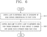
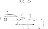
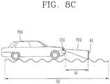
- a control device including a sensing unit to sense a topographical state of a currently-driving road surface of a vehicle, a head lamp to emit light to the front of the vehicle, the head lamp outputting the light to a reference area when the topographical state of the road surface is a first state, and a processor to control the head lamp to output the light to the reference area even though the topographical state of the road surface is changed into a second state different from the first state.
- the processor may detect through the sensing unit a point where the topographical state of the road surface is the second state, and decide a control time point of the head lamp on the basis of the detected point and a driving speed of the vehicle.
- the processor may control a light output direction of the head lamp such that the light is continuously output to the reference area, on the basis of the topography of the road surface corresponding to the second state, detected through the sensing unit.
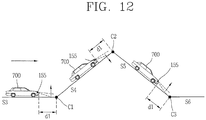
- the head lamp may include a left lamp and a right lamp.
- the processor may control the left lamp and the right lamp in different manners on the basis of the topography of the road surface corresponding to the second state.
- the processor may detect a driving state of the vehicle through the sensing unit, and control the head lamp emitting the light in a preset manner, on the basis of a change in the driving state of the vehicle.
- the processor controls the head lamp to output the light to the reference area even though a body of the vehicle with the head lamp is tilted due to the change in the driving state of the vehicle.
- the processor may detect through the sensing unit a zone in which a light output area to the currently-driving road surface is changed by more than a reference, and change the light output direction of the head lamp before a predetermined distance from a start point of the zone.
- the processor may detect a surrounding area of a currently-driving lane of the vehicle through the sensing unit, and control the head lamp not to output the light to the surrounding area when the surrounding area meets a preset condition.
- the processor may control the head lamp to output light only to a currently-driving lane of the vehicle.
- the processor may control the head lamp to output light up to another end opposite to one end of a lane to change, the lane to change being adjacent to the currently-driving lane, when a manipulation for the vehicle is determined as a lane change.
- a vehicle in accordance with one embodiment of the present invention may include a control device described in this specification.
- a method for controlling a vehicle in accordance with one embodiment of the present invention may include detecting a topographical state of a currently-driving road surface of a vehicle, emitting light to a reference area in a topography of the road surface which is in a first state, and controlling the head lamp to output light to the reference area even though the topography of the road surface is changed into a second state difference from the first state.
- the present invention can provide a control device, capable of controlling a light output direction to prevent an accident when a state of a currently-driving road surface and a driving state of a vehicle change.
- a singular representation may include a plural representation unless it represents a definitely different meaning from the context.
- a vehicle according to an embodiment of the present invention may be understood as a conception including cars, motorcycles and the like. Hereinafter, the vehicle will be described based on a car.
- the vehicle according to the embodiment of the present invention may be a conception including all of an internal combustion engine car having an engine as a power source, a hybrid vehicle having an engine and an electric motor as power sources, an electric vehicle having an electric motor as a power source, and the like.
- the vehicle according to the embodiment of the present invention may be an autonomous vehicle.
- a left side of a vehicle refers to a left side in a driving direction of the vehicle, and a right side of the vehicle refers to a right side in the driving direction.
- a front side is a forward driving direction
- a rear side is a backward driving direction
- FIG. 1 is a view illustrating appearance of a vehicle in accordance with an embodiment of the present invention.
- a vehicle 700 may include wheels 103FR, 103FL, 103RL, ..., which turn by a power source, and a steering apparatus for adjusting a driving (ongoing) direction of the vehicle 700.
- the steering apparatus may include a steering wheel.
- a user may decide a driving direction of the vehicle 700 using the steering wheel.
- a steering input received through the steering apparatus may be transferred to the steering wheel.
- the steering apparatus and the steering wheel may be connected to each other electrically or mechanically.
- the steering wheels may preferably be the front wheels 103FL and 103FR, but alternatively all of the front wheels 103FL and 103FR and the rear wheels 103RR may operate as the steering wheels.
- FIGS. 2A to 2C are views illustrating various embodiments of a camera module included in a control device according to the present invention.
- a camera unit 200a may include an image sensor (e.g., CCD or CMOS), a lens 203, and a light shield 202 for shielding a part of light incident on the lens 203.
- an image sensor e.g., CCD or CMOS
- a lens 203 e.g., a lens 203
- a light shield 202 for shielding a part of light incident on the lens 203.
- the camera unit 200a may have a structure which is attachable on or detachable from an inner ceiling or a wind shield of the vehicle 700.
- the camera unit 200a may acquire surrounding images of the vehicle 700.
- the camera unit 200a may acquire front or rear images of the vehicle 700.
- the images acquired through the camera unit 200a may be transmitted to an image processor (not illustrated).
- the image acquired through the camera unit 200a may be referred to as a mono image.
- the camera unit 200a described with reference to FIG. 2A may be referred to as a mono camera unit or a single camera unit.
- a camera unit 200b may include a first camera 211a and a second camera 211b.
- the first camera 211a may include a first image sensor (e.g., CCD or CMOS) and a first lens 213a.
- the second camera 211b may include a second image sensor (e.g., CCD or CMOS) and a second lens 213b.
- the camera unit 200b may include a first light shield 212a and a second light shield 212b for partially shielding light incident on the first lens 213a and the second lens 213b.
- the camera unit 200b may have a structure which is attachable on or detachable from an inner ceiling or a wind shield of the vehicle 700.
- the camera unit 200b may acquire surrounding images of the vehicle 700.
- the camera unit 200b may acquire front or rear images of the vehicle 700.
- the images acquired through the camera unit 200b may be transmitted to an image processor (not illustrated).
- the images acquired through the first camera 211a and the second camera 211b may be referred to as stereo images.
- the camera unit 200b described with reference to FIG. 2B may be referred to as a stereo camera unit.
- a camera unit 200c may include a plurality of cameras 221a, 221b 221c and 221d.
- the left camera 221a may be disposed within a case surrounding a left side mirror.
- the right camera 221c may be disposed within a case surrounding a right side mirror.
- the front camera 221d may be disposed on one area of a front bumper, and the rear camera 221b may be disposed on one area of a trunk lid.
- the plurality of cameras 221a, 221b, 221c and 221d may be disposed on the left side, the rear side, the right side and the front side of the vehicle, respectively.
- Each of the plurality of cameras 221a, 221b, 221c and 221d may include an image sensor (e.g., CCD or CMOS) and a lens.
- the camera unit 200c may acquire surrounding images of the vehicle.
- the camera unit 200c may acquire front, rear, left and right images of the vehicle.
- the images acquired through the camera unit 200c may be transmitted to an image processor (not illustrated).
- the images acquired through the plurality of cameras 221a, 221b, 221c and 221d of FIG. 2C or a merged image of the acquired images may be referred to as an around view image.
- the camera unit 200c described with reference to FIG. 2C may be referred to as an around view camera unit.
- FIG. 3 is a block diagram illustrating a vehicle 700 in accordance with an embodiment of the present invention.
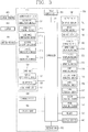
- the vehicle 700 may include a communication unit 710, an input unit 720, a sensing unit 760, an output unit 740, a vehicle operating unit 750, a memory 730, an interface unit 780, a controller 770, a power supply unit 790, a control device 100, a driver status monitoring (DSM) system, and a vehicle display device 400.
- a communication unit 710 an input unit 720, a sensing unit 760, an output unit 740, a vehicle operating unit 750, a memory 730, an interface unit 780, a controller 770, a power supply unit 790, a control device 100, a driver status monitoring (DSM) system, and a vehicle display device 400.
- DSM driver status monitoring
- the communicating unit 710 may include at least one module allowing wireless communications between the vehicle 700 and a mobile terminal 600, between the vehicle 700 and an external server 601 or between the vehicle 700 and another vehicle 602. Also, the communication unit 710 may include at least one module connecting the vehicle 700 to at least one network.
- the communication unit 710 may include a broadcast receiving module 711, a wireless Internet module 712, a short-range communication module 713, a location information module 714, an optical communication module 715, and a V2X communication module 716.
- the communication unit 710 may receive weather information.
- the communication unit 710 may receive the weather information from the outside through the broadcast receiving module 711, the wireless Internet module 712 or the V2X communication module 716.
- the communication unit 710 may receive (driving) road information.
- the communication unit 710 may recognize a location of the vehicle 700 through the location information module 714, and receive road information corresponding to the location of the vehicle 700 through the wireless Internet module 712 or the V2X communication module 716.
- the communication unit 710 may receive traffic light change information from the external server 601 through the V2X communication module 716.
- the external server 601 may be a server which is located at a traffic control station which controls traffic conditions.
- the broadcast receiving module 711 receives a broadcast signal and/or broadcast associated information from an external broadcast managing entity via a broadcast channel.
- broadcasting includes radio broadcasting or TV broadcasting.
- the wireless Internet module 712 refers to a module that is configured to facilitate wireless Internet access and may be mounted within the vehicle 700 or detachably coupled to the vehicle 700.
- the wireless Internet module 712 transmits and/or receives wireless signals via communication networks according to wireless Internet technologies.
- wireless Internet access examples include Wireless LAN (WLAN), Wireless Fidelity (Wi-Fi), Wi-Fi Direct, Digital Living Network Alliance (DLNA), Wireless Broadband (WiBro), Worldwide Interoperability for Microwave Access (WiMAX), High Speed Downlink Packet Access (HSDPA), High Speed Uplink Packet Access (HSUPA), Long Term Evolution (LTE), LTE-advanced (LTE-A) and the like.
- the wireless Internet module 712 transmits/receives data according to one or more of such wireless Internet technologies, and other Internet technologies as well.
- the wireless Internet module 712 receives weather information, road traffic condition information (e.g., transport protocol expert group (TPEG)) from the external server 601.
- TPEG transport protocol expert group
- the short-range communication module 713 facilitates short-range communications. Suitable technologies for implementing such short-range communications include BLUETOOTH TM , Radio Frequency IDentification (RFID), Infrared Data Association (IrDA), Ultra-WideBand (UWB), ZigBee, Near Field Communication (NFC), Wireless-Fidelity (Wi-Fi), Wi-Fi Direct, Wireless USB (Wireless Universal Serial Bus), and the like.
- RFID Radio Frequency IDentification
- IrDA Infrared Data Association
- UWB Ultra-WideBand
- ZigBee Near Field Communication
- NFC Near Field Communication
- Wi-Fi Wireless-Fidelity
- Wi-Fi Direct Wireless USB (Wireless Universal Serial Bus), and the like.
- the short-range communication module 713 may construct short-range wireless area networks to support short-range communications between the vehicle 700 and at least one external device. For example, the short-range communication module 713 may exchange data with the mobile terminal 600 in a wireless manner. The short-range communication module 713 may receive weather information, road traffic condition information (e.g., transport protocol expert group (TPEG) from the mobile terminal 600. If the user gets in the vehicle 700, the user's mobile terminal 600 and the vehicle 700 may be paired with each other automatically or by an application executed by the user.
- TPEG transport protocol expert group
- the location information module 714 is a module for acquiring the location of the vehicle 700, and representatively includes a global positioning system (GPS) module.
- GPS global positioning system
- the location of the vehicle can be acquired using signals sent from a GPS satellite.
- the optical communication module 715 may include a light transmitting portion and a light receiving portion.
- the light receiving portion may receive information by converting a light signal into an electric signal.
- the light receiving portion may include a photo diode (PD) for receiving light.
- the photo diode may convert light into an electric signal.
- the light receiving portion may receive information related to a front vehicle based on light emitted from a light source included in the front vehicle.
- the light transmitting portion may include at least one light emitting element for converting an electric signal into a light signal.
- the light emitting element is preferably a light emitting diode (LED).
- the light transmitting portion converts an electric signal into a light signal and transmits the light signal to outside.
- the light transmitting portion may transmit a light signal to outside in a manner of turning on or off the light emitting element corresponding to a predetermined frequency.
- the light transmitting portion may include a plurality of light emitting element arrays.
- the light transmitting portion may be integrated with lamps provided on the vehicle 700.
- the light transmitting portion may be at least one of a head lamp, a rear lamp, a brake lamp, a turn indicator lamp and a clearance lamp.
- the light transmission module 715 may exchange data with another vehicle 602 through light communication.
- the V2X communication module 716 is a module for performing wireless communication with the external server 601 or the another vehicle 602.
- the V2X communication module 716 includes a module which can implement a vehicle-to-vehicle (V2V) communication protocol or a vehicle-to-infra (V2I) communication protocol.
- the vehicle 700 may perform wireless communications with the external server 601 and the another vehicle 602 through the V2X communication module 716.
- the input unit 720 may include a camera, the camera unit 200a, 200b, 200c, a microphone 723 and a user input unit 724.
- the microphone 723 may process an external sound signal into electric data.
- the processed data may be variously used according to a function currently performed in the vehicle 700.
- the microphone 723 may convert a user's voice command into electric data.
- the converted electric data may be transferred to the controller 770.
- the camera or microphone 723 may alternatively be a component included in the sensing unit 760, other than a component included in the input unit 720.
- the user input unit 724 allows the user to input information.
- the controller 770 may control an operation of the vehicle 700 to correspond to the input information.
- the user input unit 724 may include a touch input device or a mechanical input device.
- the user input unit 724 may be disposed on one area of the steering wheel. In this instance, the user (driver) can manipulate the user input unit 724 with fingers while holding the steering wheel.
- the user input unit 724 may receive a turn signal input.
- the sensing unit 760 senses a signal associated with driving and the like.
- the sensing unit 760 may include a collision sensor, a wheel sensor, a velocity sensor, a tilt sensor, a weight sensor, a heading sensor, a yaw sensor, an acceleration sensor, a gyro sensor, a position module, a vehicle forward/backward movement sensor, a battery sensor, a fuel sensor, a tire sensor, a steering sensor by a turn of a handle, a vehicle internal temperature sensor, a vehicle internal humidity sensor, a rain sensor, an illumination sensor, a tire air pressure sensor, an ultrasonic sensor, a radar, a light detection and ranging (LiADAR) and the like.
- LiADAR light detection and ranging
- the sensing unit 760 may acquire sensing signals with respect to information related to a car collision, an orientation of the vehicle, a location (GPS) of the vehicle, an angel of the vehicle, a driving speed of the vehicle, an acceleration of the vehicle, a tilt of the vehicle, a forward/backward movement of the vehicle, a battery, a fuel, a tire, a vehicle lamp, internal temperature of the vehicle, internal humidity of the vehicle, raining, a turning angle of a steering wheel, ambient brightness, tire air pressure and the like.
- GPS location
- the sensing unit 760 may further include an acceleration paddle sensor, a pressure sensor, an engine speed sensor, an air flow sensor (AFS), an air temperature sensor (ATS), a water temperature sensor (WTS), a throttle position sensor (TPS), a TDC sensor, a crank angle sensor (CAS), and the like.
- AFS air flow sensor
- ATS air temperature sensor
- WTS water temperature sensor
- TPS throttle position sensor
- TDC crank angle sensor
- CAS crank angle sensor
- the ultrasonic sensor, the radar or the LiADAR may detect an object and track the object.
- the ultrasonic sensor, the radar or the LiADAR may calculate a distance from the detected object and a relative speed with respect to the object.
- the ultrasonic sensor, the radar or the LiADAR may detect a dangerous situation.
- a processor included in the ultrasonic sensor, the radar or the LiADAR may detect such dangerous situation based on the distance from the object.
- the sensing unit 760 may include a posture detecting sensor.
- the posture detecting sensor may sense a posture of the vehicle.
- the posture detecting sensor may generate vehicle posture information.
- the posture detecting sensor may include the yaw sensor, the acceleration sensor, the gyro sensor and the tilt sensor.
- the sensing unit 760 may include a wind sensor.
- the wind sensor may detect a direction or speed of the wind.
- the wind sensor may generate wind direction information or wind speed information.
- the wind sensor may include an ultrasonic type wind sensor.
- the wind sensor may measure the speed and direction of the wind using the property that a transfer speed of ultrasonic waves transferred through an air medium increases or decreases due to the wind.
- the sensing unit 760 may include a biometric information detecting portion.
- the biometric information detecting portion detects biometric information related to a passenger for acquisition.
- the biometric information may include fingerprint information, iris-scan information, retina-scan information, hand geometry information, facial recognition information, and voice recognition information.
- the biometric information detecting portion may include a sensor for detecting the biometric information related to the passenger.
- an internal camera and the microphone 723 may operate as sensors.
- the biometric information detecting portion may acquire hand geometry information and facial recognition information through the internal camera.
- the output unit 740 is configured to output information processed in the controller 770, and may include a display module 741, an audio output module 742 and a haptic output module 743.
- the display module 741 may output information processed in the controller 770.
- the display module 741 may output vehicle-related information.
- the vehicle-related information may include vehicle control information for a direct control of the vehicle, or vehicle driving assist information for guiding the driving of a driver of the vehicle.
- the vehicle-related information may include vehicle status information notifying a current status of the vehicle or vehicle driving information related to a driving state of the vehicle.
- the display module 741 may include at least one of a liquid crystal display (LCD), a thin film transistor-liquid crystal display (TFT-LCD), an organic light emitting diode (OLED), a flexible display, a 3-dimensional (3D) display, an e-ink display, and combinations thereof.
- LCD liquid crystal display
- TFT-LCD thin film transistor-liquid crystal display
- OLED organic light emitting diode
- flexible display a 3-dimensional (3D) display
- 3D 3-dimensional
- e-ink display and combinations thereof.
- the display module 741 may be layered or integrated with a touch sensor to implement a touch screen.
- the touch screen may function as the user input unit 724 providing a user input interface between the vehicle 700 and the user and simultaneously provide an output interface between the vehicle 700 and the user.
- the display module 741 may include a touch sensor which senses a touch input applied to the display module 741, so as to receive a control command applied in a touching manner.
- the touch sensor may sense the touch, and the controller 770 may generate a control command corresponding to the touch.
- Contents input by the touching method may be characters, numbers, instructions in various modes, or menu items to be designated.
- the display module 741 may include a cluster which allows the driver to check vehicle status information or vehicle driving information while driving the vehicle.
- the cluster may be located on a dashboard. In this instance, the driver may check information output on the cluster while viewing the front of the vehicle.
- the display module 741 may be implemented as a head up display (HUD).
- HUD head up display
- information may be output through a transparent display provided on a wind shield.
- the display module 741 may be provided with a projection module and thus output information through an image projected on the wind shield.
- the audio output module 742 converts an electric signal sent from the controller 770 into an audio signal and outputs the audio signal.
- the audio output module 742 may include a speaker and the like.
- the audio output module 742 can output sound corresponding to an operation of the user input unit 724.
- the haptic output module 743 generates a tactile output.
- the haptic output module 743 may vibrate a steering wheel, a safety belt or a seat to make the user recognize such output.
- the vehicle operating unit 750 may control operations of various vehicle devices.
- the vehicle operating unit 750 may receive a control signal from the steering apparatus.
- the vehicle operating unit 750 may control each device based on the control signal.
- the vehicle operating unit 750 may include a power source operating portion 751, a steering operating portion 752, a brake operating portion 753, a lamp operating portion 754, an air conditioner operating portion 755, a window operating portion 756, an airbag operating portion 757, a sunroof operating portion 758, and a suspension operating portion 759.
- the power source operating portion 751 may perform an electronic control for the power source within the vehicle 700.
- the power source operating portion 751 may perform an electronic control for the engine. Accordingly, an output torque or the like of the engine may be controlled.
- the power source operating portion 751 is the engine, the engine output torque may be limited according to the control of the controller 770, thereby limiting speed of the vehicle.
- the power source operating portion 751 may perform a control for the motor, thereby controlling a rotation speed, torque and the like of the motor.
- the power source operating portion 751 may receive an acceleration control signal from the steering apparatus or the control device 100. The power source operating portion 751 may control the power source according to the received acceleration control signal.
- the steering operating portion 752 may perform an electronic control for the steering apparatus within the vehicle 700. Accordingly, a moving (driving, ongoing) direction of he vehicle can change.
- the steering operating portion 752 may receive a steering control signal from the steering apparatus or the control device 100.
- the steering operating portion 752 may control the steering apparatus to be steered according to the received steering control signal.
- the brake operating portion 753 may perform an electronic control for the brake apparatus 153 within the vehicle 700.
- the braking operating portion 753 may control an operation of a brake (or brake apparatus) provided on a wheel to reduce speed of the vehicle 700 or stop the vehicle 700.
- the brake operating portion 753 may differently control operations of brakes disposed on a left wheel and a right wheel to adjust a moving direction of the vehicle 700 to left or right.
- the brake operating portion 753 may receive a deceleration control signal from the steering apparatus or the control device 100.
- the brake operating portion 753 may control the brake apparatus according to the received deceleration control signal.
- the lamp operating portion 754 may control lamps disposed within or outside the vehicle to be turned on or ff. Also, the lamp operating portion 754 may control intensity, direction and the like of light. For example, the lamp operating portion 754 may control head lamps (low beam, high beam), turn indicator lamps, brake lamps and the like.
- the air conditioner operating portion 755 may perform an electronic control for an air conditioner within the vehicle 700. For example, when internal temperature of the vehicle is high, the air conditioner operating portion 755 may control the air conditioner to be activated to supply cold air into the vehicle.
- the window operating portion 756 may perform an electronic control for a window apparatus within the vehicle 700.
- the window operating portion 756 may control left and right windows provided on side surfaces of the vehicle to be open or closed.
- the airbag operating portion 757 may perform an electronic control for an airbag apparatus within the vehicle 700.
- the airbag operating portion 757 may control an airbag to be deployed upon exposed to danger.
- the sunroof operating portion 758 may perform an electronic control for a sunroof apparatus within the vehicle 700.
- the sunroof operating portion 758 may control the sunroof to be open or closed.
- the suspension operating portion 759 may perform an electronic control for a suspension apparatus within the vehicle 700. For example, when a bump is present on a road surface, the suspension operating portion 759 may control the suspension apparatus to reduce vibration transferred to the vehicle 700.
- the suspension operating portion 759 may receive a suspension control signal from the steering apparatus or the control device 100. The suspension operating portion 759 may control the suspension apparatus according to the received suspension control signal.
- the memory 730 is electrically connected to the controller 770.
- the memory 730 may store basic data for units, control data for controlling operations of units and input/output data.
- the memory 730 may store various data for overall operations of the vehicle 700, such as programs for processing or controlling the controller 770.
- the memory 730 may include one or more types of storage mediums including a flash memory type, a hard disk type, a solid state disk (SSD) type, a silicon disk drive (SDD) type, a multimedia card micro type, a card-type memory (e.g., SD or XD memory, etc), a Random Access Memory (RAM), a Static Random Access Memory (SRAM), a Read-Only Memory (ROM), an Electrically Erasable Programmable Read-Only Memory (EEPROM), a Programmable Read-Only memory (PROM), a magnetic memory, a magnetic disk, an optical disk, and the like.
- the vehicle 700 may also be operated in relation to a network storage device that performs the storage function of the memory 730 over a network, such as the Internet.
- the memory 730 may be integrated with the controller 770.
- the interface unit 780 may serve as a path allowing the vehicle 700 to interface with various types of external devices connected thereto.
- the interface unit 780 may be provided with a port connectable with the mobile terminal 600, and connected to the mobile terminal 600 through the port. In this instance, the interface unit 780 may exchange data with the mobile terminal 600.
- the interface unit 780 may serve as a path for supplying electric energy to the connected mobile terminal 600.
- the interface unit 780 supplies electric energy supplied from the power supply unit 790 to the mobile terminal 600 according to the control of the controller 770.
- the interface unit 780 may serve as a path allowing the vehicle 700 to interface with various types of external devices connected thereto.
- the interface unit 780 may include any of wired or wireless ports, external power supply ports, wired or wireless data ports, memory card ports, ports for connecting a device having an identification module, audio input/output (I/O) ports, video I/O ports, earphone ports, and the like.
- the vehicle 700 may perform assorted control functions associated with a connected external device, in response to the external device being connected to the interface unit 780.
- the controller 770 may control an overall operation of each unit, apparatus or component within the vehicle 700.
- the controller 770 may be referred to as an electronic control unit (ECU).
- the controller 770 may be implemented in hardware configuration by using at least one of digital signal processors (DSPs), digital signal processing devices (DSPDs), programmable logic devices (PLDs), field programmable gate arrays (FPGAs), processors, controllers, micro controllers, microprocessors, and electric units performing other functions.
- DSPs digital signal processors
- DSPDs digital signal processing devices
- PLDs programmable logic devices
- FPGAs field programmable gate arrays
- processors controllers, micro controllers, microprocessors, and electric units performing other functions.
- the power supply unit 790 may supply power required for operations of components according to the control of the controller 770. Specifically, the power supply unit 790 may receive power supplied from an internal battery (not illustrated) of the vehicle 700.
- the steering apparatus or the control device 100 may exchange data with the controller 770. Various information, data or control signals generated in the steering apparatus may be output to the controller 770.
- the steering apparatus may be the control device described with reference to FIGS. 1 to 3 .
- a driver status monitoring (DSM) system (not illustrated) is a system of sensing a driver's status and controlling the vehicle 700 according to the driver's status.
- the DSM system may include an input device such as an internal camera, a microphone and the like.
- the DSM system may monitor the driver's status, such as whether the driver is looking at the front, dozing off, eating food, manipulating a device or the like. Also, the DSM system may sense the driver's concentration on driving during the driving.
- the DSM system may include a photoplenthysmogram (PPG) sensor.
- the PPG sensor may be disposed on one area of the steering wheel which is contactable with the user's (e.g., the driver's) body.
- the PPG sensor may be disposed on one area of a steering wheel rim.
- the DSM system may acquire a biometric signal of the driver through the PPG sensor and analyze the acquired biometric signal.
- the DSM system may acquire a biometric signal and generate driver condition information as the driver status information.
- the DSM system may acquire biometric information and generate information related to the driver's excited condition as the driver status information.
- the DSM system may analyze a driver image acquired through the internal camera, and generate information related to the driver's dozing state as the driver status information.
- the DSM system may analyze a driver image acquired through the internal camera, and generate information related to the driver's device manipulating state.
- the DSM system may provide the driver status information to the steering apparatus or the control device 100.
- the vehicle display device 400 may exchange data with the controller 770.
- the controller 770 may receive navigation information from the vehicle display device 400 or a separate navigator (not illustrated).
- the navigation information may include information related to a preset destination, path information based on the destination, map information related to driving of the vehicle, or vehicle location information.
- the vehicle 700 disclosed herein may include the control device 100.
- the control device 100 may control various lamps provided in the vehicle 700.
- the various lamps may include head lamps configured to emit visible light to the front of the vehicle, rear lamps configured to emit visible light to the rear of the vehicle, turn indicator lamps and the like.
- the head lamp 155 may be configured by one or more of a headlight, a lamp emitting at least one of low beam and high beam based on a user request, and a turn indicator lamp.
- the control device 100 disclosed herein may be an independent device (structure or component) that controls at least one component (e.g., the head lamp 155, the sensing unit 760 and the like) provided in the vehicle 700.
- at least one component e.g., the head lamp 155, the sensing unit 760 and the like
- the control apparatus 100 may generally control various units, components, apparatuses, and the like described in FIG. 3 . That is, the control device 100 may be the controller 770 of the vehicle 700. That is, hereinafter, operations, functions and controls described in relation to the control device 100 may be performed by the controller 770 of the vehicle 700.
- control device 100 may be referred to as a lamp control device, a vehicle control device, a vehicle assist device or the like, from the perspective of controlling the lamps provided on the vehicle.
- control device 100 is a single independent device (structure or component).
- control device 100 according to the present invention will be described in more detail, with reference to FIG. 4 .
- the following description will be applied to a case where the control device 100 provided in the vehicle is configured as the independent device.
- FIG. 4 is a block diagram illustrating a control device in accordance with an embodiment of the present invention.
- the control device 100 may include a camera module 200, a communication unit 110, an input unit 120, an interface unit 130, a memory 140, an output unit 150, a head lamp 155, a sensing unit 160, a processor 170 and a power supply unit 190.
- the camera module 200 may acquire surrounding images of the vehicle.
- Data, signals or information generated in the camera module 200 are transmitted to the processor 170.
- the camera module 200 may be the camera unit 200a, 200b, 200c illustrated in FIGS. 2A to 2C .
- the camera module 200 may be the mono camera unit 200a.
- the mono camera unit 200a may acquire a mono image as the surrounding image of the vehicle.
- the camera module 200 may be the stereo camera unit 200b.
- the stereo camera unit 200b may acquire a stereo image as the surrounding image of the vehicle.
- the camera module 200 may be an around view camera unit 200c.
- the around view camera unit 200c may acquire an around view image as the surrounding image of the vehicle.
- the communication unit 110 may exchange data with the mobile terminal 600, the server 601 or the another vehicle 602 in a wireless manner. Specifically, the communication unit 110 may exchange data with the mobile terminal of the driver of the vehicle in a wireless (or wired) manner. Examples of such wireless communication method may include various communication methods, such as Bluetooth, WiFi direct, WiFi, APiX, NFC, etc.
- the communication unit 110 may receive weather information, road traffic condition information, for example, TPEG information from the mobile terminal 600 or the server 601. Meanwhile, the vehicle assist device 100 may also transmit recognized real-time information to the mobile terminal 600 or the server 601.
- the control device 100 may perform pairing with each other automatically or by the user's execution of an application.
- the control device 100 may be referred to as a vehicle assist device.
- the communication unit 110 may receive traffic light change information from the external server 601.
- the external server 601 may be a server located in a traffic control station for controlling traffic.
- the communication unit 110 may receive weather information from the external server 601.
- the external server 601 may be a server of an organization or an operator providing the weather information.
- the communication unit 110 may receive, for each region, fine dust information, smog information or yellow dust information from the external server 601.
- the input unit 120 may include a user input unit 121 and an audio input unit 122.
- the user input unit 121 may include a plurality of buttons or a touch screen.
- the user input unit 121 may turn on the control device 100 through the plurality of buttons or the touch screen.
- the user input unit 121 may also perform various input operations.
- the audio input unit 122 may receive the user's voice input.
- the audio input unit 122 may include a microphone switching the voice input into an electric signal.
- the audio input unit 122 may receive the user's voice to turn on the vehicle assist device 100.
- the user input unit 121 may also perform other various input operations.
- the input unit 120 may be the input unit 720 illustrated in FIG. 3 .
- the input unit 120 may refer to the vehicle driving portion 750.
- the input unit 120 may include a lamp operating portion 754 for turning on/off the head lamp 155.
- the interface unit 130 may allow for receiving information, signals or data, or externally transmitting information, signals or data processed or generated in the processor 170. To this end, the interface unit 130 may perform data communication with the controller 770, the vehicle display device 400, the sensing unit 760, the vehicle driving portion 750 and the like provided in the vehicle, through wired or wireless communication technologies.
- the interface unit 130 may allow for receiving navigation information through data communications with the controller 770, the vehicle display device 400 or a separate navigator.
- the navigation information may include information related to a preset destination, path information based on the destination, map information related to driving of the vehicle, or vehicle location information. Meanwhile, the navigation information may include location information related to the vehicle on a road.
- the interface unit 130 may allow for receiving sensor information from the controller 770 or the sensing unit 160, 760.
- the sensor information may include information related to at least one of an orientation of the vehicle, a location (GPS) of the vehicle, an angel of the vehicle, a driving speed of the vehicle, an acceleration of the vehicle, a tilt of the vehicle, a forward/backward movement of the vehicle, a battery, a fuel, a tire, a vehicle lamp, internal temperature of the vehicle, external temperature of the vehicle, internal humidity of the vehicle, external humidity of the vehicle, and raining.
- GPS location
- the sensor information may be acquired from a heading sensor, a yaw sensor, a gyro sensor, a position module, a vehicle forward/backward movement sensor, a wheel sensor, a vehicle velocity sensor, a vehicle tilt detecting sensor, a battery sensor, a fuel sensor, a tire sensor, a steering sensor by a turn of a handle, a vehicle internal temperature sensor, a vehicle external temperature sensor, a vehicle internal humidity sensor, a vehicle external humidity sensor, a rain sensor, a GPS sensor and the like.
- vehicle driving information the vehicle orientation information, the vehicle location information, the vehicle angle information, vehicle velocity information, the vehicle tilt information and the like, all related to the driving of the vehicle.
- the interface unit 130 may receive passenger information.
- the passenger information may be information received through an input device.
- the passenger information may be information acquired through a passenger detecting sensor (e.g., a camera capturing a passenger's state).
- the passenger information may be information received from a mobile terminal belonging to the passenger.
- the memory 140 may store various data for an overall operation of the control device 100, such as programs for processing or control of the processor 170.
- the memory 140 may store data for checking a predetermined object.
- the memory140 may store information for checking (or verifying) what the object corresponds to, according to a preset algorithm, when the predetermined object is detected from an image acquired through the camera module 200.
- the memory 140 may be various storage media, such as ROM, RAM, EPROM, a flash drive, a hard drive and the like, in hardware configuration.
- the memory 140 may be integrally formed with the processor 170.
- the output unit 150 may generate a visual, audible or tactile output, and may include at least one of the display unit 151, the audio output module 152, the haptic module and an optical output module.
- the display unit 151 may implement a touch screen as being layered or integrated with a touch sensor.
- the touch screen may function as the user input unit 121 providing a user input interface between the control device 100 and the user and simultaneously providing an output interface between the control device 100 and the user.
- the output unit 150 of the control device 100 may be the output unit 740 illustrated in FIG. 3 , or a separate device.
- the display unit 151 may also be the display device 400 illustrated in FIG. 3 , or a separate device.
- the head lamp 155 may be provided on the front of the vehicle 700.
- the head lamp 155 may be configured as various light sources.
- the head lamp 155 may emit light by a light source including at least one of a bulb, a micro LED, a matrix LED, an OLED and a laser diode.
- the head lamp 155 may also be implemented by at least one of a light source, a reflector reflecting light output from a light source, a shield forming a preset low-beam pattern, a structure changing a color of light, and a projection lens.
- the head lamp 155 may output (emit, irradiate) at least one of low beam and high beam to the front of the vehicle according to a user request.
- the head lamp 155 may be turned on/off, for example, when a user request is received through the lamp operating portion 754 or the input unit 120. when the head lamp 155 is turned on, light (e.g., visible light) may be output to the front of the vehicle.
- light e.g., visible light
- the head lamp 155 and the lamp operating portion 754 are preferably provided at the vehicle 700. Meanwhile, for the sake of explanation, the head lamp 155 and the lamp operating portion 754 will be described as being included in the control device 100.
- the control device 100 may include a sensing unit 160.
- the sensing unit 160 may be the sensing unit 760 illustrated in FIG. 3 .
- the sensing unit 160 may be the sensing unit 760 itself provided in the vehicle, or a separate component.
- the structure of the sensing unit 760 provided in the vehicle will be applied equally/similarly.
- sensing unit 160 is included in the control device 100. Also, the same/like description of the sensing unit 760 provided in the vehicle and the use of the sensing unit 760 provided in the vehicle will be applied to description of the sensing unit 160 and the use of the sensing unit 160.
- the processor 170 may control an overall operation of each unit within the control device 100.
- the processor 170 may be electrically connected to each unit, component or apparatus within the control device 100.
- the processor 170 may process surrounding images acquired through the camera module 200.
- the processor 170 may process the vehicle surrounding image into a computer vision-based signal.
- the processor 170 may merge a plurality of images received from the around view camera module 200c of FIG. 2C .
- the plurality of images may be images received from the plurality of cameras 221a, 221b, 221c and 221d of FIG. 2C .
- the processor 170 may generate an around view image or an omnidirectional image by merging the plurality of images.
- the around view image may be a top view image.
- the processor 170 may detect at least one object based on each of the images acquired from the plurality of cameras 221a, 221b, 221c and 221d of FIG. 2C ). Or, the processor 170 may detect at least one object based on the around view image.
- the processor 170 may detect at least one object based on the omnidirectional image.
- the lamp control device 100 may track a movement of the detected object.
- the processor 170 may perform a lane detection (LD), a vehicle detection (VD), a pedestrian detection (PD), a brightspot detection (BD), a traffic sign recognition (TSR), a road surface detection, a structure detection and the like.
- LD lane detection
- VD vehicle detection
- PD pedestrian detection
- BD brightspot detection
- TSR traffic sign recognition
- the processor 170 may detect an object based on at least one of intensity, a color, histogram, a feature point, a shape, a space position and a motion.
- the processor 170 may verify the detected object.
- the processor 170 may verify the detected object using an identifying method using a neural network, a support vector machine (SVM) method, an identifying method by AdaBoost using a Haar-like characteristic, a histograms of oriented gradients (HOG) technology, or the like.
- the processor 170 may perform such verification by comparing the object detected from the surrounding image of the vehicle with data stored in the memory 140.
- the processor 170 may track the verified object.
- the processor 170 may calculate a motion or a motion vector of the verified object and track a movement and the like of the object based on the calculated motion or motion vector.
- processor 170 for hardware implementation, may be implemented using at least one of application specific integrated circuits (ASICs), digital signal processors (DSPs), digital signal processing devices (DSPDs), programmable logic devices (PLDs), field programmable gate arrays (FPGAs), processors, controllers, micro-controllers, microprocessors, electronic units designed to perform the functions described herein.
- ASICs application specific integrated circuits
- DSPs digital signal processors
- DSPDs digital signal processing devices
- PLDs programmable logic devices
- FPGAs field programmable gate arrays
- processors controllers, micro-controllers, microprocessors, electronic units designed to perform the functions described herein.
- the power supply unit 190 may supply power required for an operation of each component according to the control of the processor 170. Specifically, the power supply unit 190 may receive power supplied from an internal battery of the vehicle and the like.
- control device 100 described in FIG. 4 may be a component or device independently provided in the vehicle 700 or the controller 770 itself.
- the control device 100 which can include at least one of those components may control various lamps provided on the vehicle.
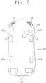
- FIG. 5 is a conceptual view illustrating a head lamp provided on a vehicle in accordance with one embodiment of the present invention.
- the vehicle 700 disclosed herein may include lamps 154, 155 and 156 controllable by the control device 100 (or the controller 770), and a brake apparatus 153.
- the lamps may include a head lamp 155 provided on a front of the vehicle and emitting (outputting) visible light to the front of the vehicle, rear lamps 154 provided on a rear of the vehicle and emitting visible light to the rear of the vehicle, and turn indicator lamps 156.
- the rear lamps 154 and the turn indicator lamps 156 are irrespective of the present invention, so detailed description thereof will be omitted.
- the head lamp 155 may be turned on when a user request is received through the lamp operating portion 754 or the input unit 120.
- the head lamp 155 may output low beams to the front of the vehicle 700.
- the low beam may form a preset cutoff line, which may have various shapes according to designs.
- the head lamp 155 may output high beams to the front of the vehicle 700 when a high beam output is requested by the user.
- high beam output When the high beam output is requested, low beams and high beams may generally be output simultaneously, and an area to which the high beams are output and an area to which the low beams are output may partially overlap each other.
- the low beam or the high beam may be output to the front of the vehicle under the control of the control device 100.
- the processor 170 of the control device 100 may control the head lamp 155 to output light to the front of the vehicle.
- the head lamp 155 may be turned on when surrounding brightness detected through the sensing unit 160, 760 is darker than reference brightness. For example, when the surrounding brightness of the vehicle detected through the sensing unit 160 is darker than a preset brightness, the processor 170 may control the head lamp 155 to output light to the front of the vehicle.
- the head lamp 155 may be configured to vary a light output direction.
- the head lamp 155 may vary a direction of outputting light (i.e., light output direction) by the control of the processor 170 of the control device 100.
- the processor 170 may control the head lamp 155 to output light in an upward direction (e.g., height direction H).
- This example illustrates that the head lamp 155 can change the light output direction to the upward direction, but the present invention may not be limited to this.
- the head lamp 155 may vary the light output direction into every direction.
- the light output direction of the head lamp 155 may be changed (varied) by at least one of various components (e.g., a light source, a reflector, a shield, a forming body (or structure) or a lens) forming the head lamp 155, or by a transforming member which is disposed on a housing of the head lamp 155 or at an outside of the head lamp 155.
- various components e.g., a light source, a reflector, a shield, a forming body (or structure) or a lens
- the operation that the processor 170 controls (changes, varies) the light output direction of the head lamp 155 may be executed by at least one of the components of the head lamp, the housing or the transforming member.
- the present invention may not be limited to this, but can employ any means, structure, function or the like which is capable of changing (varying) the output direction of light which is output from the head lamp.
- a technology of varying the light output direction of the head lamp corresponds to a generally-known technology, and thus detailed description thereof will be omitted.
- control device 100 may control the head lamp 155 in an optimized manner, such that the user can safely drive the vehicle.
- control device capable of controlling head lamp by an optimized control device will be described in more detail.
- FIG. 6 is a flowchart illustrating a representative control method in accordance with the present invention
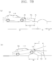
- FIGS. 7A and 7B are conceptual views illustrating the control method of FIG. 6 .
- the control device 100 may include a sensing unit 160 which is configured to detect a topographical state of a road surface (lane, road, etc.) that the vehicle 700 is currently moving.
- the sensing unit 160 may be a sensing unit 760 provided on the vehicle 700 or a separate sensing unit 160 provided on the control device 100.
- the sensing unit 160 may detect a topographical state of a road surface on which the vehicle 700 is currently driven.
- the topographical state of the road surface may refer to an external shape of the road surface (the ground, a road, a lane) where the vehicle is driven.
- the topographical state of the road surface may include a first state, and a second state different from the first state.
- the first state may refer to a flat state, for example.
- the topographical state of the road surface where the vehicle is currently driven may be referred to as the first state.
- the first state may include a road surface which is perpendicular to a gravitational direction (e.g., a direction in parallel to a horizon), and also a topography on which a body of the currently-moving vehicle is in parallel to a road surface for a predetermined time.
- a gravitational direction e.g., a direction in parallel to a horizon
- the first state may include a state that an obstacle in a preset size (e.g., an obstacle which does not cause a change in a tilt of the vehicle body) is laid on a road surface.
- a topography of a road surface corresponding to the first state may also include a case where the vehicle body is not tilted by a suspension connected to wheels of the vehicle even though an obstacle in a predetermined size is laid on the road surface.
- the topographical state of the road surface may be the first state.
- the topography of the road surface in the first state may refer to a topography at which the tilt of the vehicle body is 0° based on the road surface, or a topography on which the vehicle body and the road surface are in parallel to each other.
- the second state may include a topographical state of a road surface in which the vehicle body is not in parallel to the road surface due to a shape of the road surface (a shape of the ground).
- a shape of the road surface a shape of the ground.
- the topography of the road surface in the second state may include a topography on which the tilt of the vehicle (body of the vehicle) is changed for a predetermined time.
- This topography may include a topography with at least one of a speed bump, a port hole and an obstacle in a preset size or more.
- the sensing unit 160 may include various sensors for detecting (sensing) a topographical state of a road surface on which the vehicle is currently driven.
- the sensing unit 160 may detect the topographical state of the road surface where the vehicle 700 is currently driven, by using at least one of an image sensor (e.g., the camera 200), an infrared sensor, a radar sensor, a LiADAR sensor, an ultrasonic sensor, an acceleration sensor, a gyroscopic sensor, a collision sensor, a tire sensor, and a tire air pressure sensor.
- control device 100 may include head lamp 155 that emits (outputs) light to the front of the vehicle 700.
- the head lamp 155 may be configured to irradiate (emit, output) light to a reference area in a topography of a road surface in the first state.
- light is output to a reference area in a topography of a road surface corresponding to a first state (S610).
- the processor 170 of the control device 100 may turn on the head lamp 155 based on a user request or a surrounding environment.
- the head lamp 155 may emit light to the reference area.
- a reference area A1 may refer to an area A1 where light is emitted to a space, which is spaced apart from one point (e.g., the head lamp 155) of the vehicle 700 by a preset distance d1, within a topography S1 of a road surface corresponding to the first state.
- the reference area A1 may refer to an area where light 702 emitted from the head lamp 155 is output to a virtual plane P, which is spaced apart from one point (e.g., the head lamp 155) of the vehicle 700 by the preset distance d1.
- the virtual plane P may be perpendicular to the topography of the road surface corresponding to the first state.
- the preset distance d1 may be decided (changed) by a user setting or the processor 170. Also, the preset distance d1 may be defined variously within a light-outputtable distance.
- the preset distance d1 may be the closest distance from the vehicle 700 in an area A2 where the light 702 output from the head lamp 155 reaches the road surface.
- the reference area may also be the area A2 in which the light 702 output from the head lamp 155 reaches the road surface corresponding to the first state.
- the shape and size of the reference area A1, A2 may differ according to at least one of a type of the head lamp 155, a light source, a shield, a reflector, a forming body, a projection lens, a low beam and high beam.
- the reference area is the area A1 in which the light 702 output from the head lamp 155 reaches the space (the virtual plane P), which is spaced apart from one point of the vehicle 700 by the predetermined distance d1.
- the head lamp is controlled to output light to the reference area even though the topography of the road surface changes into a second state different from the first state (S620).
- the processor 170 may detect a topography of a road surface, on which the vehicle is currently driven, through the sensing unit 160.
- the sensing unit 150 may detect a topography of the road surface corresponding to the second state different from the first state.
- the processor 170 may control the head lamp 155 to output light to the reference area even though the topography of the road surface changes into the second state different from the first state.
- the light 702 emitted from the head lamp 155 may be output to the reference area A1, which is spaced apart from one point of the vehicle 700 by the predetermined distance d1.
- the processor 170 may control the head lamp 155 to output the light 702 continuously to the reference area A1 spaced apart from the one point of the vehicle 700 by the predetermined distance d1 (i.e., the reference area A1 to which light is output in the first state S1).
- the processor 170 may control a light output direction of the head lamp 155 such that the light 702 is continuously emitted to the reference area A1.
- the body of the vehicle may be tilted such that a front portion of the vehicle is raised up.
- the processor 170 may change the light output direction of the head lamp 155 into one direction (e.g., a downward direction), such that the light 702 can be output to the reference area A1.
- the processor 170 may change the light output direction back into the upward direction such that the light 702 output from the head lamp 155 can continuously be output to the reference area A1.
- the body of the vehicle may be tilted such that the front portion of the vehicle faces a lower side.
- the processor 170 may change the light output direction of the head lamp 155 into a direction opposite to the one direction (e.g., an upward direction), such that the light 702 can be output to the reference area A1.
- the processor 170 may differently control a degree that the light output direction of the head lamp 155 changes, such that the light 702 emitted from the head lamp 155 can continuously be output to the reference area A1, even though a changed degree of the tilt of the body of the vehicle differs according to the topography of the road surface corresponding to the second state S2.
- the present invention can make the light 702 continuously output to the reference area A1 even though the tilt of the body of the vehicle is continuously changed according to the topography of the road surface corresponding to the second state.
- the processor 170 may allow the light 702 emitted from the head lamp 155 to be continuously output to the reference area, which is spaced apart from the one point of the vehicle by the predetermined distance, even though the tilt of the vehicle changes in response to the vehicle entering the topography of the road surface corresponding to the second state, different from the first state.
- the present invention can provide a vehicle capable of controlling the light output direction of the head lamp such that light can always be output to a predetermined area even though the tilt of the vehicle changes.
- the present invention can maintain light to be output to a predetermined area even though a topography of a road surface changes, thereby minimizing user's fatigue.
- FIGS. 8A , 8B , 8C and 9 are conceptual views illustrating a method of controlling head lamp according to a state of a road surface on which a vehicle is currently driven.
- the processor 170 may detect a point where a topography of a road surface corresponding to the second state is started through the sensing unit 160.
- the processor 170 may sense through the sensing unit 160 a point where the topography of the road surface is in the second state, and decide a control time point of the head lamp 155 based on the sensed point and a driving speed of the vehicle700.
- the processor 170 may detect a point where the topographical state of the road surface is changed into the second state S2 different from the first state S1. Afterwards, the processor 170 may calculate a distance between the point S2 which is in the second state and a part of the vehicle (e.g., the front wheels 103FL and 103FR of the vehicle).
- a part of the vehicle e.g., the front wheels 103FL and 103FR of the vehicle.
- the processor 170 may calculate a time point that the vehicle 700 (e.g., the front or rear wheels of the vehicle) enters the topography of the road surface corresponding to the second state, on the basis of the calculated distance and a driving speed V of the vehicle which is currently driven.
- the vehicle 700 e.g., the front or rear wheels of the vehicle
- the processor 170 may decide the calculated time point as the control time point of the head lamp 155.
- the processor 170 may calculate a time point that the body of the vehicle is tilted on the basis of the point where the topographic state of the road surface is changed from the first state S1 into the second state S2 (or a distance D between the point and the part of the vehicle (front or rear wheels)) and the driving speed of the vehicle. The processor 170 may then change the light output direction of the head lamp 155 at the calculated time point.
- the time point that the body of the vehicle is tilted can accurately be determined, and an unintentional change of the light output direction of the head lamp can be prevented.
- the processor 170 may control the light output direction of the head lamp 155 such that the light 701 can continuously be output to the reference area A1, on the basis of the topography of the road surface corresponding to the second state S2 which is detected through the sensing unit 160.
- the processor 170 may determine the topography of the road surface corresponding to the second state, which is different from the first state, through the sensing unit 160.
- the processor 170 may determine a size of a section of the road surface corresponding to the second state, a shape of the road surface, a height of the road surface, and the like, through the sensing unit 160.
- the processor 170 may change the light output direction of the head lamp 155 such that the light 702 is output to the reference area A1, on the basis of the topography of the road surface (e.g., the height of the road surface) corresponding to the second state.
- the processor 170 may determine (decide) that the topography of the road surface corresponding to the second state S2 detected through the sensing unit 160 has a first height h1.
- the processor 170 may change the light output direction of the head lamp 155, such that the light 702 output to the reference area A1 in the first state S1 can be maintained, even though the vehicle 700 enters the topography of the road surface corresponding to the second state S2.
- the processor 170 may change the light output direction into one direction (e.g., downward direction) by a first angle ⁇ 1, such that the light 702 can be emitted to the reference area A1.
- the processor 170 may change the light output direction into one direction (e.g., downward direction) by a second angle ⁇ 2 greater than the first angel ⁇ 1, such that the light 702 can be emitted to the reference area A1.
- the processor 170 may control a degree (angle) by which the light output direction of the head lamp 155 is changed to be in proportion to the variation of the tilt of the vehicle body.
- the degree (angel) by which the light output direction of the head lamp 155 is changed may be in proportion to the variation of the tilt of the vehicle body.
- the changed direction of the light output direction of the head lamp 155 may be a direction opposite to the tilted direction of the vehicle body.
- the processor 170 may change the light output direction of the head lamp into an upward direction.
- the processor 170 may change the light output direction of the head lamp into a downward direction.
- the processor 170 may change the light output direction of the head lamp 155 continuously into downward and upward directions, such that the light 702 can be kept output to the reference area A1 spaced apart from the part of the vehicle 700 by the predetermined distance d1.
- the head lamp 155 may include a left lamp 155L and a right lamp 155R.
- the processor 170 may control the left lamp 155L and the right lamp 155R in a simultaneous or individual manner.
- the processor 170 may control the left lamp 155L and the right lamp 155R in different manners on the basis of a topography of a road surface corresponding to the second state.
- the processor 170 may control the left lamp and the right lamp when a left side and a right side of the vehicle body are moved by a predetermined height or more due to the topography of the road surface corresponding to the second state.
- the processor 170 may control a lamp corresponding to one of the left lamp and the right lamp when one of the left side and the right side of the vehicle body is moved by the predetermined height or more due to the topography of the road surface corresponding to the second state.
- a topography 900a of a road surface corresponding to the second state may be a topography (e.g., speed bump) in which the left and right sides of the vehicle body are moved by the predetermined height or more.
- a part e.g., front wheels 103FL and 103FR
- both of the left and right sides of the vehicle body are lifted up by the predetermined height or more. That is, the front side of the vehicle is tilted upwardly.
- the processor 170 may control both of the left lamp 155L and the right lamp 155R to emit light to the reference area A1.
- the processor 170 may change the light output direction of each of the left lamp 155L and the right lamp 155R such that the light can continuously be output to the reference area A1.
- the light output directions of the left lamp 155L and the right lamp 155R can all be changed into the downward direction.
- a topography 900b of a road surface corresponding to the second state may be a topography (e.g., port hole) in which one of the left and right sides of the vehicle body is lifted up by a predetermined height or more.
- a part e.g., front wheels 103FL and 103FR
- only one e.g., right side of the left and right sides of the vehicle body is lifted up by the predetermined height or more.
- the vehicle when a part of a lane is destroyed, the vehicle may be moved by a predetermined height or more at only one of left and right sides thereof.
- the processor 170 may determine which of the left side and the right side of the vehicle body is to be moved by the predetermined height or more, on the basis of the topography 900b of the road surface corresponding to the second state, sensed through the sensing unit 160.
- the processor 170 may control only one (e.g., right lamp 155R) of the left lamp 155L and the right lamp 155R.
- the foregoing embodiment has illustrated only the case where only the front wheels of the vehicle enter the topography 900a, 900b of the road surface corresponding to the second state, but the described method can similarly be applied to a case where the rear wheels of the vehicle enter the topography 900a, 900b of the road surface corresponding to the second state.
- the processor may change the light output direction of at least one of the left lamp and the right lamp into a downward direction when the front wheels of the vehicle enter the topography, whereas changing the light output direction of at least one of the left lamp and the right lamp into an upward direction when the rear wheels of the vehicle enters the topography.
- the present invention can control each of a right lamp and a left lamp even in such various topographies (i.e., shapes) of a road surface corresponding to a second state. Accordingly, the present invention can provide a head lamp capable of continuously outputting light to a reference area in an optimized manner, and a control device for controlling the same.
- the present invention can change a light output direction based on a driving state of a vehicle.
- description will be given in more detail of a method of changing a light out direction on the basis of a driving state of a vehicle, with reference to the accompanying drawings.
- FIGS. 10 and 11 are conceptual views illustrating a method of controlling head lamp according to a change in a driving state of a vehicle.
- the processor 170 may detect a driving state of the vehicle 700 through the sensing unit 160.
- the driving state of the vehicle may include a stopped state, a driving state at a uniform speed, acceleration driving, deceleration driving, driving on a curved road and the like.
- the processor 170 may control the head lamp 155 emitting light in a preset manner on the basis of the change in the driving state of the vehicle.
- the change in the driving state of the vehicle may include every case of driving the vehicle such that the vehicle body is tilted.
- the change in the driving state of the vehicle may include acceleration driving or deceleration driving to cause the vehicle body to be tilted.
- the control in the preset manner may refer to controlling the light 702 emitted from the head lamp 155 to be continuously output to the reference area A1 spaced apart from the one point of the vehicle 700 by the predetermined distance d1.
- the processor 170 may control the head lamp 155 to keep outputting light to the reference area A1 even though the body of the vehicle 700 having the head lamp 155 is tilted due to the change in the driving state of the vehicle 700.
- the change in the driving state of the vehicle may include a case where an acceleration of the vehicle is more than a reference value.
- the processor 170 may determine it as the change in the driving state of the vehicle. This instance may be referred to as fast acceleration driving.
- the reference value may be defined as an acceleration value accelerating the vehicle as fast as the body of the vehicle being tilted.
- the vehicle body When the acceleration of the vehicle is more than the reference value, the vehicle body may be tilted such that the front side of the vehicle is lifted up.
- the processor 170 may change the light output direction of the head lamp into a downward direction, such that the light 702 emitted from the head lamp 155 can be output to the reference area A1, even though the vehicle body is tilted.
- the change in the driving state of the vehicle may include a case where a braking force of the vehicle is more than a predetermined value.
- the vehicle body may be tilted such that the front side of the vehicle is set down. This case may be referred to as rapid braking driving.
- the predetermined value may be defined as a braking force of braking the vehicle such that the vehicle body is tilted.
- the vehicle body When the braking force of the vehicle is more than the predetermined value, the vehicle body may be tilted such that the front side of the vehicle is set down.
- the processor 170 may change the light output direction of the head lamp 155 into an upward direction, such that the light 702 emitted from the head lamp 155 can be output to the reference area A1, even though the vehicle body is tilted.
- the present invention can provide the head lamp, capable of continuously outputting the light 702 to the reference area A1, which is spaced apart from the part (e.g., front wheels) of the vehicle by the predetermined distance d1, even though the vehicle body is tilted according to the driving state in addition to the topographical state of the road surface, and a control device for controlling the same.
- the light output direction of the head lamp may be decided based on a braking distance of the vehicle which is currently driven.
- the processor 170 may calculate a braking distance on the basis of the driving state of the vehicle 700 and a state of a road surface on which the vehicle 700 is currently driven. Afterwards, the processor 170 may decide the light output direction of the head lamp 155 based on the calculated braking distance.
- the driving state of the vehicle 700 may include a driving speed, a current weight, a braking force, a maximum braking force, a surrounding environment and the like of the vehicle.
- the driving state of the vehicle 700 may be detected by the sensing unit 160.
- the state of the road surface on which the vehicle 700 is currently moving may include frictional force, a material, a tilt based on a horizon and the like.
- the state of the road surface may also be detected through the sensing unit 160.
- the processor 170 may calculate the braking distance (or a time to collision (TTC)) of the vehicle on the basis of the driving state of the vehicle and the state of the road surface.
- TTC time to collision
- the braking distance may be proportional to the driving speed and the weight of the vehicle, and inversely proportional to the braking force and the frictional force of the vehicle.
- the processor 170 may change the light output direction such that the light 702 emitted from the head lamp 155 is output in an upward direction when a long braking distance is calculated (in other words, when the speed of the vehicle is fast, or the weight of the vehicle is heavy).
- the processor 170 may control the light output direction such that the light is output, starting from a point spaced apart from the vehicle by a first distance d3, when the calculated braking distance is a first distance Q1.
- the processor 170 may change the light output direction into an upward direction such that the light is output, starting from a point spaced apart from the vehicle 700 by a second distance d4 farther than the first distance d3.
- the change in the light output direction may be executed at a time point that the braking force of the vehicle is applied.
- the present invention can control the light 702 emitted from the head lamp 155 to reach a place farther away from the vehicle when the braking distance of the vehicle is far (or the driving speed of the vehicle is fast), thereby providing an effect of remarkably reducing an accident incidence rate.
- the present invention may provide a new control method capable of reducing an accident incidence rate.
- FIG. 12 is a conceptual view illustrating a method of controlling head lamp based on a sate of a road surface in accordance with another embodiment of the present invention.
- the processor 170 may detect a zone, in which an area (size of a portion) that light is output (i.e., light output area) to a currently-driving road surface of the vehicle is changed by more than a reference, through the sensing unit 160.
- the zone in which the light output area to the currently-driving road surface is changed by more than the reference may be an uphill topography with a positive tilt or a downhill topography with a negative tilt on the basis of a tile of a currently-driving lane.
- the zone in which the light output area to the currently-driving road surface is changed by more than the reference, as illustrated in FIG. 12 , may be the uphill topography S4 with the positive tilt on the basis of the currently-driving road surface S3.
- the zone in which the light output area to the currently-driving road surface is changed by more than the reference may be a road surface S6 with a positive tilt, rather than the tilt of the currently-driving road surface S5.
- the zone in which the light output area to the currently-driving road surface is changed by more than the reference may be a downhill topography with a negative tilt, rather than the tilt of the currently-driving flat road surface S5.
- the zone in which the light output area to the currently-driving road surface is changed by more than the reference may be the road surface S5 with the negative tilt, rather than the currently-driving road surface S4.
- the positive tilt may refer to a tilt that the front side of the vehicle is raised up.
- the negative tilt may refer to a tilt that the front side of the vehicle is set down.
- a light output area i.e., a size (area) of a portion to which light is output
- a light output area i.e., a size of a portion to which light is output
- the processor 170 may detect areas S3-S4, S4-S5, S5-S6 where the light-output area to the road surface is changed by the reference or more, and change the light output direction of the head lamp 155 before a predetermined distance d1 from start points C1, C2 and C3 of the areas.
- the reference may refer to a reference size that the light output area to the road surface is changed as the tilt of the vehicle is increased by a reference or more.
- the reference may be decided (or changed) by a user setting or the control of the processor.
- the processor 170 may change the light output direction such that light is output in an upward direction.
- the processor 170 may change the light output direction such that light is output in a downward direction.
- the processor 170 may detect the area (road surface) S4 with the positive tilt rather than the tilt of the road surface S3. In this instance, a size that light output on the road surface S3 is output to the area S4 is reduced smaller than the size that light emitted on the road surface S3 is output on the road surface S3.
- the processor 170 may determine that the topography located in front of the vehicle is an uphill topography (or a topography with a positive tilt rather than the currently-driving road surface).
- the processor 170 may change the light output direction of the light emitted from the head lamp 155 into the upward direction.
- the present invention can ensure a user's field of vision by allowing the vehicle to output light farther at an uphill topography (or a topography with a positive tilt rather than a tilt of a currently-driving road surface).
- the processor 170 may detect the area (road surface) S5 with the negative tilt rather than the tilt of the road surface S4. In this instance, the size that light emitted on the road surface S4 reaches the road surface S5 is increased more than the size that the light emitted on the road surface S4 is output to the road surface S4.
- the processor 170 may determine that the topography where the front side of the vehicle is located is a downhill topography (or a topography with a negative tilt rather than the currently-driving road surface.
- the processor 170 may change the light output direction of the head lamp 155 into a downward direction.
- the present invention can ensure a field of vision with respect to an area close to the vehicle, which fails to be ensured in a downhill topography, in a manner of outputting light more closely in a downhill topography (or a topography with a negative tilt rather than the tilt of the currently-driving road surface.
- the predetermined distance d1 may be decided (or changed) by a user setting or the control of the processor.
- the predetermined distance d1 may be defined as a distance between the closest point from the vehicle, among points that light emitted from the head lamp 155 is irradiated on the road surface, and one point (e.g., head lamp) of the vehicle.
- the processor 170 may decide a degree that the light output direction of the head lamp changes, on the basis of a changed degree of the light output area to the road surface.
- the processor 170 may change the light output direction more greatly.
- the degree of changing the light output direction may be decided in proportion to the tilt difference between the currently-driving road surface and the zone where the light output area is changed.
- the present invention can provide head lamp capable of remarkably reducing an accident incidence rate, at a predetermined section where a topography of a road surface is changed into an uphill or downhill topography, as well as in a situation that a light output direction is suddenly changed due to a topography of a road surface, and a control device for controlling the same.
- the head lamp can variously be controlled in association with a driving lane.
- FIGS. 13A and 13B are conceptual views illustrating a method of controlling head lamp in association with a driving lane.
- the processor 170 may detect a currently-driving lane of the vehicle 700 through the sensing unit 160.
- the lane for example, may be detected by analyzing images received through the camera 200.
- the processor 170 may also detect a surrounding region of the currently-driving lane of the vehicle 700 through the sensing unit 160.
- the processor 170 may control the head lamp 155 not to output the light 702 to the surrounding region when the surrounding region meets a preset condition.
- the light 702 emitted from the head lamp155 may be output over the currently-driving lane 1330a (i.e., between 1300a and 1300b.
- the processor 170 may control the head lamp 155 not to output the light 702b to the surrounding region 1310.
- the preset condition may include a topography higher than the currently-driving lane by a predetermined height, an obstacle with a predetermined height, or the like.
- the processor 170 may control the head lamp 155 (e.g., right lamp 155R) not to output light to the right region 1310.
- the processor 170 may control the head lamp 155 (e.g., left lamp 155L) not to output light to the left region.
- the head lamp 155 e.g., left lamp 155L
- the processor 170 may control the head lamp 155 to output(or not to output) light 702b to a preset object 1320 when the preset object 1320 is detected at the surrounding region 1310 of the currently-driving lane through the sensing unit 160.
- the preset object 1320 may include a person, an animal, a road sign, etc. Also, the preset object 1320 may be decided by a user setting or the control of the processor 170.
- the processor 170 may track a preset object when the preset object (e.g., another vehicle which is currently driven in an opposite direction) is detected at a surrounding region (e.g., opposite driving lane) of the currently-driving lane through the sensing unit 160.
- the preset object e.g., another vehicle which is currently driven in an opposite direction
- a surrounding region e.g., opposite driving lane
- the processor 170 may control the head lamp 155 to output (or not to output) light only to the preset object on the basis of the tracking result of the preset object.
- the processor 170 may detect a currently-driving lane 1330a of the vehicle 700 through the sensing unit 160.
- the processor 170 may control the head lamp 155 (155L and 155R) to output light 702c only to the currently-driving lane 1330a of the vehicle 700.
- the processor 170 may control the head lamp 155 (155L and 155R) to output light 702d to a lane 1330b to change, from one end 1300b of the lane 1330b, adjacent to the currently-driving lane 1330a, to another end 1300c opposite to the one end 1300b of the lane 1330b to change.
- the manipulation for the vehicle may correspond to the user's manipulation for the steering wheel 752.
- the processor 1700 may determine the manipulation for the vehicle as a lane change.
- the processor 170 may control the head lamp 155 to output light to an entire range of the lane to change.
- the processor 170 may decide a speed of changing the light output direction such that the head lamp can output light up to the opposite end 1300c of the lane 1330b, on the basis of the manipulation for the vehicle.
- the processor 170 may change the light output direction in proportion to a rotating speed of the steering wheel when the manipulation for the vehicle is the rotation of the steering wheel.
- the processor 170 can fast change the light output direction such that light can be output up to the opposite end 1300b of the lane 1330b to change, when the rotation speed of the steering wheel is fast.
- the present invention can provide a control device capable of controlling the head lamp in an optimized manner according to a surrounding environment of a currently-driving lane or a driving manipulation for the vehicle.
- the aforementioned control device 100 may be included in the vehicle 700.
- the aforementioned operation or control method of the control device 100 may also be equally/similarly applied as the operation or control method of the vehicle 700.
- control method of the vehicle may include detecting a topographical state of a currently-driving road surface of the vehicle, outputting light to a reference area in a topography of a road surface corresponding to a first state, and controlling head lamp to output the light to the reference area even though the topography of the road surface is changed into a second state different from the first state.
- the controlling may be configured to control the head lamp outputting the light in a preset manner on the basis of a change in a driving state of the vehicle.
- Each of the steps may be performed by a controller 770 provided in the vehicle 700, as well as the control device 100.
- every function, configuration or control method performed by the control device 100 can be performed by the controller 770 of the vehicle 700. That is, every control method described herein can also be applied to the control method of the vehicle and the control method of the control device.
- the present invention can be implemented as computer-readable codes in a program-recorded medium.
- the computer-readable medium may include all types of recording devices each storing data readable by a computer system. Examples of such computer-readable media may include hard disk drive (HDD), solid state disk (SSD), silicon disk drive (SDD), ROM, RAM, CD-ROM, magnetic tape, floppy disk, optical data storage element and the like. Also, the computer-readable medium may also be implemented as a format of carrier wave (e.g., transmission via an Internet).
- the computer may include the controller 180 of the terminal.
Landscapes
- Engineering & Computer Science (AREA)
- Mechanical Engineering (AREA)
- Physics & Mathematics (AREA)
- Automation & Control Theory (AREA)
- Mathematical Physics (AREA)
- Transportation (AREA)
- General Engineering & Computer Science (AREA)
- General Physics & Mathematics (AREA)
- Multimedia (AREA)
- Theoretical Computer Science (AREA)
- Lighting Device Outwards From Vehicle And Optical Signal (AREA)
Abstract
Description
- The present invention relates to a control device mounted on a vehicle and a method for controlling the vehicle.
- A vehicle is an apparatus capable of moving a user in the user-desired direction, and a representative example may be a car.
- A vehicle may be provided with various types of lamps. In general, the vehicle includes various vehicle lamps having a lighting function of facilitating articles or objects near the vehicle to be recognized during driving at night, and a signaling function of notifying a driving state of the vehicle to other vehicles or pedestrians.
- For example, the vehicle may include devices operating in a manner of directly emitting light using lamps, such as a head lamp emitting light to a front side to ensure a driver's view, a brake lamp turned on when slamming the brake on, turn indicator lamps used upon a left turn or a right turn.
- As another example, reflectors for reflecting light to facilitate the vehicle to be recognized from outside are mounted on front and rear sides of the vehicle.
- Installation criteria and standards of the lamps for the vehicle are regulated as rules to fully exhibit each function.
- Meanwhile, as development of an advanced deriving assist system (ADAS) is actively undergoing in recent time, development of a technology for optimizing user's convenience and safety while driving a vehicle is required.
- As one effort, it is needed to develop a technology of optimizing safety during driving a vehicle by controlling lamps.
- Therefore, an aspect of the detailed description is to provide a control device mounted on a vehicle, capable of controlling lamps provided on the vehicle in an optimized manner, and a method for controlling the vehicle.
- Another aspect of the detailed description is to provide a control device mounted on a vehicle, capable of emitting light in an optimized manner on the basis of at least one of a state of a road surface on which the vehicle is currently moving and a driving state of the vehicle, and a method for controlling the vehicle.
- Another aspect of the detailed description is to provide a control device mounted on a vehicle, capable of emitting light in a manner of minimizing a user's fatigue even though at least one of a state of a road surface on which the vehicle is currently moving and a driving state of the vehicle is changed, and a method for controlling the vehicle.
- Another aspect of the detailed description is to provide a control device mounted on a vehicle, capable of ensuring a front viewing field in an optimized manner on the basis of at least one of a state of a road surface on which the vehicle is currently moving and a driving state of the vehicle, and a method for controlling the vehicle.
- Problems to be solved in the present invention may not be limited to the aforementioned, and other unmentioned problems to be solved will be understood by those skilled in the art from the following description.
- To achieve these and other advantages and in accordance with the purpose of this specification, as embodied and broadly described herein, there is provided a control device, including a sensing unit to sense a topographical state of a currently-driving road surface of a vehicle, a head lamp to emit light to the front of the vehicle, the head lamp outputting the light to a reference area when the topographical state of the road surface is a first state, and a processor to control the head lamp to output the light to the reference area even though the topographical state of the road surface is changed into a second state different from the first state.
- In one exemplary embodiment disclosed herein, the processor may detect through the sensing unit a point where the topographical state of the road surface is the second state, and decide a control time point of the head lamp on the basis of the detected point and a driving speed of the vehicle.
- In one exemplary embodiment disclosed herein, the processor may control a light output direction of the head lamp such that the light is continuously output to the reference area, on the basis of the topography of the road surface corresponding to the second state, detected through the sensing unit.
- In one exemplary embodiment disclosed herein, the head lamp may include a left lamp and a right lamp. The processor may control the left lamp and the right lamp in different manners on the basis of the topography of the road surface corresponding to the second state.
- In one exemplary embodiment disclosed herein, the processor may detect a driving state of the vehicle through the sensing unit, and control the head lamp emitting the light in a preset manner, on the basis of a change in the driving state of the vehicle.
- In one exemplary embodiment disclosed herein, the processor controls the head lamp to output the light to the reference area even though a body of the vehicle with the head lamp is tilted due to the change in the driving state of the vehicle.
- In one exemplary embodiment disclosed herein, the processor may detect through the sensing unit a zone in which a light output area to the currently-driving road surface is changed by more than a reference, and change the light output direction of the head lamp before a predetermined distance from a start point of the zone.
- In one exemplary embodiment disclosed herein, the processor may detect a surrounding area of a currently-driving lane of the vehicle through the sensing unit, and control the head lamp not to output the light to the surrounding area when the surrounding area meets a preset condition.
- In one exemplary embodiment disclosed herein, the processor may control the head lamp to output light only to a currently-driving lane of the vehicle. The processor may control the head lamp to output light up to another end opposite to one end of a lane to change, the lane to change being adjacent to the currently-driving lane, when a manipulation for the vehicle is determined as a lane change.
- A vehicle in accordance with one embodiment of the present invention may include a control device described in this specification.
- A method for controlling a vehicle in accordance with one embodiment of the present invention may include detecting a topographical state of a currently-driving road surface of a vehicle, emitting light to a reference area in a topography of the road surface which is in a first state, and controlling the head lamp to output light to the reference area even though the topography of the road surface is changed into a second state difference from the first state.
- Details of other embodiments will be disclosed in the detailed description and the accompanying drawings.
- According to embodiments of the present invention, at least one of the following effects can be obtained.
- First, even though a state of a currently-driving road surface is changed, light can continuously be output to a reference area, which may result in minimizing user's fatigue.
- Second, even though a driving state of a vehicle is changed, light can continuously be output to a reference area, whereby a change in an area to which light emitted from a head lamp is output can be prevented, thereby minimizing an accident incidence rate.
- Third, the present invention can provide a control device, capable of controlling a light output direction to prevent an accident when a state of a currently-driving road surface and a driving state of a vehicle change.
- Further scope of applicability of the present application will become more apparent from the detailed description given hereinafter. However, it should be understood that the detailed description and specific examples, while indicating preferred embodiments of the invention, are given by way of illustration only, since various changes and modifications within the spirit and scope of the invention will become apparent to those skilled in the art from the detailed description.
- The accompanying drawings, which are included to provide a further understanding of the invention and are incorporated in and constitute a part of this specification, illustrate exemplary embodiments and together with the description serve to explain the principles of the invention.
- In the drawings:
-
FIG. 1 is a view illustrating appearance of a vehicle in accordance with an embodiment of the present invention; -
FIGS. 2A to 2C are views illustrating various embodiments of a camera module included in a control device according to the present invention; -
FIG. 3 is a block diagram illustrating a vehicle in accordance with an embodiment of the present invention; -
FIG. 4 is a block diagram illustrating a control device in accordance with an embodiment of the present invention; -
FIG. 5 is a conceptual view illustrating a head lamp provided on a vehicle in accordance with one embodiment of the present invention; -
FIG. 6 is a flowchart illustrating a representative control device in accordance with the present invention; -
FIGS. 7A and7B are conceptual views illustrating the control method ofFIG. 6 ; -
FIGS. 8A ,8B ,8C and9 are conceptual views illustrating a method of controlling a head lamp according to a state of a road surface on which a vehicle is currently moving; -
FIGS. 10 and11 are conceptual views illustrating a method of controlling a head lamp according to a change in a driving state of a vehicle; -
FIG. 12 is a conceptual view illustrating a method of controlling a head lamp based on a state of a road surface in accordance with another embodiment of the present invention; and -
FIG. 13A and13B are conceptual views illustrating a method of controlling a head lamp in relation to a currently-driving lane. - Description will now be given in detail according to exemplary embodiments disclosed herein, with reference to the accompanying drawings. For the sake of brief description with reference to the drawings, the same or equivalent components may be provided with the same or similar reference numbers, and description thereof will not be repeated. In general, a suffix such as "module" and "unit" may be used to refer to elements or components. Use of such a suffix herein is merely intended to facilitate description of the specification, and the suffix itself is not intended to give any special meaning or function. In the present disclosure, that which is well-known to one of ordinary skill in the relevant art has generally been omitted for the sake of brevity. The accompanying drawings are used to help easily understand various technical features and it should be understood that the embodiments presented herein are not limited by the accompanying drawings. As such, the present disclosure should be construed to extend to any alterations, equivalents and substitutes in addition to those which are particularly set out in the accompanying drawings.
- It will be understood that although the terms first, second, etc. may be used herein to describe various elements, these elements should not be limited by these terms. These terms are generally only used to distinguish one element from another.
- It will be understood that when an element is referred to as being "connected with" another element, the element can be connected with the other element or intervening elements may also be present. In contrast, when an element is referred to as being "directly connected with" another element, there are no intervening elements present.
- A singular representation may include a plural representation unless it represents a definitely different meaning from the context.
- Terms such as "include" or "has" are used herein and should be understood that they are intended to indicate an existence of several components, functions or steps, disclosed in the specification, and it is also understood that greater or fewer components, functions, or steps may likewise be utilized.
- A vehicle according to an embodiment of the present invention may be understood as a conception including cars, motorcycles and the like. Hereinafter, the vehicle will be described based on a car.
- The vehicle according to the embodiment of the present invention may be a conception including all of an internal combustion engine car having an engine as a power source, a hybrid vehicle having an engine and an electric motor as power sources, an electric vehicle having an electric motor as a power source, and the like.
- The vehicle according to the embodiment of the present invention may be an autonomous vehicle.
- A left side of a vehicle refers to a left side in a driving direction of the vehicle, and a right side of the vehicle refers to a right side in the driving direction.
- A front side is a forward driving direction, and a rear side is a backward driving direction.
-
FIG. 1 is a view illustrating appearance of a vehicle in accordance with an embodiment of the present invention. - As illustrated in
FIG. 1 , avehicle 700 may include wheels 103FR, 103FL, 103RL, ..., which turn by a power source, and a steering apparatus for adjusting a driving (ongoing) direction of thevehicle 700. - The steering apparatus may include a steering wheel. A user may decide a driving direction of the
vehicle 700 using the steering wheel. - A steering input received through the steering apparatus may be transferred to the steering wheel.
- The steering apparatus and the steering wheel may be connected to each other electrically or mechanically.
- The steering wheels may preferably be the front wheels 103FL and 103FR, but alternatively all of the front wheels 103FL and 103FR and the rear wheels 103RR may operate as the steering wheels.
-
FIGS. 2A to 2C are views illustrating various embodiments of a camera module included in a control device according to the present invention. - As illustrated in
FIG. 2A , acamera unit 200a may include an image sensor (e.g., CCD or CMOS), alens 203, and alight shield 202 for shielding a part of light incident on thelens 203. - The
camera unit 200a may have a structure which is attachable on or detachable from an inner ceiling or a wind shield of thevehicle 700. - The
camera unit 200a may acquire surrounding images of thevehicle 700. For example, thecamera unit 200a may acquire front or rear images of thevehicle 700. The images acquired through thecamera unit 200a may be transmitted to an image processor (not illustrated). - Meanwhile, the image acquired through the
camera unit 200a may be referred to as a mono image. Also, thecamera unit 200a described with reference toFIG. 2A may be referred to as a mono camera unit or a single camera unit. - Referring to
FIG. 2B , acamera unit 200b may include afirst camera 211a and asecond camera 211b. Thefirst camera 211a may include a first image sensor (e.g., CCD or CMOS) and afirst lens 213a. Thesecond camera 211b may include a second image sensor (e.g., CCD or CMOS) and asecond lens 213b. - Meanwhile, the
camera unit 200b may include afirst light shield 212a and a secondlight shield 212b for partially shielding light incident on thefirst lens 213a and thesecond lens 213b. - Meanwhile, the
camera unit 200b may have a structure which is attachable on or detachable from an inner ceiling or a wind shield of thevehicle 700. - The
camera unit 200b may acquire surrounding images of thevehicle 700. For example, thecamera unit 200b may acquire front or rear images of thevehicle 700. The images acquired through thecamera unit 200b may be transmitted to an image processor (not illustrated). - Meanwhile, the images acquired through the
first camera 211a and thesecond camera 211b may be referred to as stereo images. - The
camera unit 200b described with reference toFIG. 2B may be referred to as a stereo camera unit. - Referring to
FIG. 2C , acamera unit 200c may include a plurality ofcameras 221b - For example, the
left camera 221a may be disposed within a case surrounding a left side mirror. Theright camera 221c may be disposed within a case surrounding a right side mirror. Thefront camera 221d may be disposed on one area of a front bumper, and therear camera 221b may be disposed on one area of a trunk lid. - The plurality of
cameras cameras - The
camera unit 200c may acquire surrounding images of the vehicle. For example, thecamera unit 200c may acquire front, rear, left and right images of the vehicle. The images acquired through thecamera unit 200c may be transmitted to an image processor (not illustrated). - Meanwhile, the images acquired through the plurality of
cameras FIG. 2C or a merged image of the acquired images may be referred to as an around view image. Also, thecamera unit 200c described with reference toFIG. 2C may be referred to as an around view camera unit. -
FIG. 3 is a block diagram illustrating avehicle 700 in accordance with an embodiment of the present invention. - As illustrated in
FIG. 3 , thevehicle 700 may include acommunication unit 710, aninput unit 720, asensing unit 760, anoutput unit 740, avehicle operating unit 750, amemory 730, aninterface unit 780, acontroller 770, apower supply unit 790, acontrol device 100, a driver status monitoring (DSM) system, and avehicle display device 400. - The communicating
unit 710 may include at least one module allowing wireless communications between thevehicle 700 and amobile terminal 600, between thevehicle 700 and anexternal server 601 or between thevehicle 700 and anothervehicle 602. Also, thecommunication unit 710 may include at least one module connecting thevehicle 700 to at least one network. - The
communication unit 710 may include abroadcast receiving module 711, awireless Internet module 712, a short-range communication module 713, alocation information module 714, anoptical communication module 715, and aV2X communication module 716. - The
communication unit 710 may receive weather information. Thecommunication unit 710 may receive the weather information from the outside through thebroadcast receiving module 711, thewireless Internet module 712 or theV2X communication module 716. - The
communication unit 710 may receive (driving) road information. Thecommunication unit 710 may recognize a location of thevehicle 700 through thelocation information module 714, and receive road information corresponding to the location of thevehicle 700 through thewireless Internet module 712 or theV2X communication module 716. - The
communication unit 710 may receive traffic light change information from theexternal server 601 through theV2X communication module 716. Here, theexternal server 601 may be a server which is located at a traffic control station which controls traffic conditions. - The
broadcast receiving module 711 receives a broadcast signal and/or broadcast associated information from an external broadcast managing entity via a broadcast channel. Here, broadcasting includes radio broadcasting or TV broadcasting. - The
wireless Internet module 712 refers to a module that is configured to facilitate wireless Internet access and may be mounted within thevehicle 700 or detachably coupled to thevehicle 700. Thewireless Internet module 712 transmits and/or receives wireless signals via communication networks according to wireless Internet technologies. - Examples of such wireless Internet access include Wireless LAN (WLAN), Wireless Fidelity (Wi-Fi), Wi-Fi Direct, Digital Living Network Alliance (DLNA), Wireless Broadband (WiBro), Worldwide Interoperability for Microwave Access (WiMAX), High Speed Downlink Packet Access (HSDPA), High Speed Uplink Packet Access (HSUPA), Long Term Evolution (LTE), LTE-advanced (LTE-A) and the like. The
wireless Internet module 712 transmits/receives data according to one or more of such wireless Internet technologies, and other Internet technologies as well. Thewireless Internet module 712 receives weather information, road traffic condition information (e.g., transport protocol expert group (TPEG)) from theexternal server 601. - The short-
range communication module 713 facilitates short-range communications. Suitable technologies for implementing such short-range communications include BLUETOOTH™, Radio Frequency IDentification (RFID), Infrared Data Association (IrDA), Ultra-WideBand (UWB), ZigBee, Near Field Communication (NFC), Wireless-Fidelity (Wi-Fi), Wi-Fi Direct, Wireless USB (Wireless Universal Serial Bus), and the like. - The short-
range communication module 713 may construct short-range wireless area networks to support short-range communications between thevehicle 700 and at least one external device. For example, the short-range communication module 713 may exchange data with themobile terminal 600 in a wireless manner. The short-range communication module 713 may receive weather information, road traffic condition information (e.g., transport protocol expert group (TPEG) from themobile terminal 600. If the user gets in thevehicle 700, the user'smobile terminal 600 and thevehicle 700 may be paired with each other automatically or by an application executed by the user. - The
location information module 714 is a module for acquiring the location of thevehicle 700, and representatively includes a global positioning system (GPS) module. For example, when the vehicle uses the GPS module, the location of the vehicle can be acquired using signals sent from a GPS satellite. - The
optical communication module 715 may include a light transmitting portion and a light receiving portion. - The light receiving portion may receive information by converting a light signal into an electric signal. The light receiving portion may include a photo diode (PD) for receiving light. The photo diode may convert light into an electric signal. For example, the light receiving portion may receive information related to a front vehicle based on light emitted from a light source included in the front vehicle.
- The light transmitting portion may include at least one light emitting element for converting an electric signal into a light signal. Here, the light emitting element is preferably a light emitting diode (LED). The light transmitting portion converts an electric signal into a light signal and transmits the light signal to outside. For example, the light transmitting portion may transmit a light signal to outside in a manner of turning on or off the light emitting element corresponding to a predetermined frequency. According to an embodiment, the light transmitting portion may include a plurality of light emitting element arrays. According to an embodiment, the light transmitting portion may be integrated with lamps provided on the
vehicle 700. - For example, the light transmitting portion may be at least one of a head lamp, a rear lamp, a brake lamp, a turn indicator lamp and a clearance lamp. For example, the
light transmission module 715 may exchange data with anothervehicle 602 through light communication. - The
V2X communication module 716 is a module for performing wireless communication with theexternal server 601 or the anothervehicle 602. TheV2X communication module 716 includes a module which can implement a vehicle-to-vehicle (V2V) communication protocol or a vehicle-to-infra (V2I) communication protocol. Thevehicle 700 may perform wireless communications with theexternal server 601 and the anothervehicle 602 through theV2X communication module 716. - The
input unit 720 may include a camera, thecamera unit microphone 723 and auser input unit 724. - The
microphone 723 may process an external sound signal into electric data. The processed data may be variously used according to a function currently performed in thevehicle 700. Themicrophone 723 may convert a user's voice command into electric data. - The converted electric data may be transferred to the
controller 770. - Meanwhile, according to an embodiment, the camera or
microphone 723 may alternatively be a component included in thesensing unit 760, other than a component included in theinput unit 720. - The
user input unit 724 allows the user to input information. When information is input through theuser input unit 724, thecontroller 770 may control an operation of thevehicle 700 to correspond to the input information. Theuser input unit 724 may include a touch input device or a mechanical input device. According to an embodiment, theuser input unit 724 may be disposed on one area of the steering wheel. In this instance, the user (driver) can manipulate theuser input unit 724 with fingers while holding the steering wheel. - The
user input unit 724 may receive a turn signal input. - The
sensing unit 760 senses a signal associated with driving and the like. To this end, thesensing unit 760 may include a collision sensor, a wheel sensor, a velocity sensor, a tilt sensor, a weight sensor, a heading sensor, a yaw sensor, an acceleration sensor, a gyro sensor, a position module, a vehicle forward/backward movement sensor, a battery sensor, a fuel sensor, a tire sensor, a steering sensor by a turn of a handle, a vehicle internal temperature sensor, a vehicle internal humidity sensor, a rain sensor, an illumination sensor, a tire air pressure sensor, an ultrasonic sensor, a radar, a light detection and ranging (LiADAR) and the like. - Accordingly, the
sensing unit 760 may acquire sensing signals with respect to information related to a car collision, an orientation of the vehicle, a location (GPS) of the vehicle, an angel of the vehicle, a driving speed of the vehicle, an acceleration of the vehicle, a tilt of the vehicle, a forward/backward movement of the vehicle, a battery, a fuel, a tire, a vehicle lamp, internal temperature of the vehicle, internal humidity of the vehicle, raining, a turning angle of a steering wheel, ambient brightness, tire air pressure and the like. - Meanwhile, in addition to those sensors, the
sensing unit 760 may further include an acceleration paddle sensor, a pressure sensor, an engine speed sensor, an air flow sensor (AFS), an air temperature sensor (ATS), a water temperature sensor (WTS), a throttle position sensor (TPS), a TDC sensor, a crank angle sensor (CAS), and the like. - Meanwhile, the ultrasonic sensor, the radar or the LiADAR may detect an object and track the object. The ultrasonic sensor, the radar or the LiADAR may calculate a distance from the detected object and a relative speed with respect to the object.
- The ultrasonic sensor, the radar or the LiADAR may detect a dangerous situation. A processor included in the ultrasonic sensor, the radar or the LiADAR may detect such dangerous situation based on the distance from the object.
- The
sensing unit 760 may include a posture detecting sensor. The posture detecting sensor may sense a posture of the vehicle. The posture detecting sensor may generate vehicle posture information. - The posture detecting sensor may include the yaw sensor, the acceleration sensor, the gyro sensor and the tilt sensor.
- The
sensing unit 760 may include a wind sensor. The wind sensor may detect a direction or speed of the wind. The wind sensor may generate wind direction information or wind speed information. The wind sensor may include an ultrasonic type wind sensor. The wind sensor may measure the speed and direction of the wind using the property that a transfer speed of ultrasonic waves transferred through an air medium increases or decreases due to the wind. - The
sensing unit 760 may include a biometric information detecting portion. The biometric information detecting portion detects biometric information related to a passenger for acquisition. The biometric information may include fingerprint information, iris-scan information, retina-scan information, hand geometry information, facial recognition information, and voice recognition information. The biometric information detecting portion may include a sensor for detecting the biometric information related to the passenger. Here, an internal camera and themicrophone 723 may operate as sensors. The biometric information detecting portion may acquire hand geometry information and facial recognition information through the internal camera. - The
output unit 740 is configured to output information processed in thecontroller 770, and may include adisplay module 741, anaudio output module 742 and ahaptic output module 743. - The
display module 741 may output information processed in thecontroller 770. For example, thedisplay module 741 may output vehicle-related information. Here, the vehicle-related information may include vehicle control information for a direct control of the vehicle, or vehicle driving assist information for guiding the driving of a driver of the vehicle. Also, the vehicle-related information may include vehicle status information notifying a current status of the vehicle or vehicle driving information related to a driving state of the vehicle. - The
display module 741 may include at least one of a liquid crystal display (LCD), a thin film transistor-liquid crystal display (TFT-LCD), an organic light emitting diode (OLED), a flexible display, a 3-dimensional (3D) display, an e-ink display, and combinations thereof. - The
display module 741 may be layered or integrated with a touch sensor to implement a touch screen. The touch screen may function as theuser input unit 724 providing a user input interface between thevehicle 700 and the user and simultaneously provide an output interface between thevehicle 700 and the user. In this instance, thedisplay module 741 may include a touch sensor which senses a touch input applied to thedisplay module 741, so as to receive a control command applied in a touching manner. By using this structure, when a touch is applied to thedisplay module 741, the touch sensor may sense the touch, and thecontroller 770 may generate a control command corresponding to the touch. Contents input by the touching method may be characters, numbers, instructions in various modes, or menu items to be designated. - Meanwhile, the
display module 741 may include a cluster which allows the driver to check vehicle status information or vehicle driving information while driving the vehicle. The cluster may be located on a dashboard. In this instance, the driver may check information output on the cluster while viewing the front of the vehicle. - Meanwhile, according to an embodiment, the
display module 741 may be implemented as a head up display (HUD). When thedisplay module 741 is implemented as the HUD, information may be output through a transparent display provided on a wind shield. Or, thedisplay module 741 may be provided with a projection module and thus output information through an image projected on the wind shield. - The
audio output module 742 converts an electric signal sent from thecontroller 770 into an audio signal and outputs the audio signal. To this end, theaudio output module 742 may include a speaker and the like. Theaudio output module 742 can output sound corresponding to an operation of theuser input unit 724. - The
haptic output module 743 generates a tactile output. For example, thehaptic output module 743 may vibrate a steering wheel, a safety belt or a seat to make the user recognize such output. - The
vehicle operating unit 750 may control operations of various vehicle devices. Thevehicle operating unit 750 may receive a control signal from the steering apparatus. Thevehicle operating unit 750 may control each device based on the control signal. - The
vehicle operating unit 750 may include a powersource operating portion 751, asteering operating portion 752, abrake operating portion 753, alamp operating portion 754, an airconditioner operating portion 755, awindow operating portion 756, anairbag operating portion 757, asunroof operating portion 758, and asuspension operating portion 759. - The power
source operating portion 751 may perform an electronic control for the power source within thevehicle 700. - For example, when a fossil fuel-based engine is a power source, the power
source operating portion 751 may perform an electronic control for the engine. Accordingly, an output torque or the like of the engine may be controlled. When the powersource operating portion 751 is the engine, the engine output torque may be limited according to the control of thecontroller 770, thereby limiting speed of the vehicle. - As another example, when an electric motor is a power source, the power
source operating portion 751 may perform a control for the motor, thereby controlling a rotation speed, torque and the like of the motor. - The power
source operating portion 751 may receive an acceleration control signal from the steering apparatus or thecontrol device 100. The powersource operating portion 751 may control the power source according to the received acceleration control signal. - The
steering operating portion 752 may perform an electronic control for the steering apparatus within thevehicle 700. Accordingly, a moving (driving, ongoing) direction of he vehicle can change. - The
steering operating portion 752 may receive a steering control signal from the steering apparatus or thecontrol device 100. - The
steering operating portion 752 may control the steering apparatus to be steered according to the received steering control signal. - The
brake operating portion 753 may perform an electronic control for the brake apparatus 153 within thevehicle 700. For example, thebraking operating portion 753 may control an operation of a brake (or brake apparatus) provided on a wheel to reduce speed of thevehicle 700 or stop thevehicle 700. As another example, thebrake operating portion 753 may differently control operations of brakes disposed on a left wheel and a right wheel to adjust a moving direction of thevehicle 700 to left or right. Thebrake operating portion 753 may receive a deceleration control signal from the steering apparatus or thecontrol device 100. Thebrake operating portion 753 may control the brake apparatus according to the received deceleration control signal. - The
lamp operating portion 754 may control lamps disposed within or outside the vehicle to be turned on or ff. Also, thelamp operating portion 754 may control intensity, direction and the like of light. For example, thelamp operating portion 754 may control head lamps (low beam, high beam), turn indicator lamps, brake lamps and the like. - The air
conditioner operating portion 755 may perform an electronic control for an air conditioner within thevehicle 700. For example, when internal temperature of the vehicle is high, the airconditioner operating portion 755 may control the air conditioner to be activated to supply cold air into the vehicle. - The
window operating portion 756 may perform an electronic control for a window apparatus within thevehicle 700. For example, thewindow operating portion 756 may control left and right windows provided on side surfaces of the vehicle to be open or closed. - The
airbag operating portion 757 may perform an electronic control for an airbag apparatus within thevehicle 700. For example, theairbag operating portion 757 may control an airbag to be deployed upon exposed to danger. - The
sunroof operating portion 758 may perform an electronic control for a sunroof apparatus within thevehicle 700. For example, thesunroof operating portion 758 may control the sunroof to be open or closed. - The
suspension operating portion 759 may perform an electronic control for a suspension apparatus within thevehicle 700. For example, when a bump is present on a road surface, thesuspension operating portion 759 may control the suspension apparatus to reduce vibration transferred to thevehicle 700. Thesuspension operating portion 759 may receive a suspension control signal from the steering apparatus or thecontrol device 100. Thesuspension operating portion 759 may control the suspension apparatus according to the received suspension control signal. - The
memory 730 is electrically connected to thecontroller 770. Thememory 730 may store basic data for units, control data for controlling operations of units and input/output data. Thememory 730 may store various data for overall operations of thevehicle 700, such as programs for processing or controlling thecontroller 770. - The
memory 730 may include one or more types of storage mediums including a flash memory type, a hard disk type, a solid state disk (SSD) type, a silicon disk drive (SDD) type, a multimedia card micro type, a card-type memory (e.g., SD or XD memory, etc), a Random Access Memory (RAM), a Static Random Access Memory (SRAM), a Read-Only Memory (ROM), an Electrically Erasable Programmable Read-Only Memory (EEPROM), a Programmable Read-Only memory (PROM), a magnetic memory, a magnetic disk, an optical disk, and the like. Thevehicle 700 may also be operated in relation to a network storage device that performs the storage function of thememory 730 over a network, such as the Internet. - The
memory 730 may be integrated with thecontroller 770. - The
interface unit 780 may serve as a path allowing thevehicle 700 to interface with various types of external devices connected thereto. For example, theinterface unit 780 may be provided with a port connectable with themobile terminal 600, and connected to themobile terminal 600 through the port. In this instance, theinterface unit 780 may exchange data with themobile terminal 600. - Meanwhile, the
interface unit 780 may serve as a path for supplying electric energy to the connectedmobile terminal 600. When themobile terminal 600 is electrically connected to theinterface unit 780, theinterface unit 780 supplies electric energy supplied from thepower supply unit 790 to themobile terminal 600 according to the control of thecontroller 770. - The
interface unit 780 may serve as a path allowing thevehicle 700 to interface with various types of external devices connected thereto. Theinterface unit 780 may include any of wired or wireless ports, external power supply ports, wired or wireless data ports, memory card ports, ports for connecting a device having an identification module, audio input/output (I/O) ports, video I/O ports, earphone ports, and the like. In some cases, thevehicle 700 may perform assorted control functions associated with a connected external device, in response to the external device being connected to theinterface unit 780. - The
controller 770 may control an overall operation of each unit, apparatus or component within thevehicle 700. - The
controller 770 may be referred to as an electronic control unit (ECU). Thecontroller 770 may be implemented in hardware configuration by using at least one of digital signal processors (DSPs), digital signal processing devices (DSPDs), programmable logic devices (PLDs), field programmable gate arrays (FPGAs), processors, controllers, micro controllers, microprocessors, and electric units performing other functions. - The
power supply unit 790 may supply power required for operations of components according to the control of thecontroller 770. Specifically, thepower supply unit 790 may receive power supplied from an internal battery (not illustrated) of thevehicle 700. - The steering apparatus or the
control device 100 may exchange data with thecontroller 770. Various information, data or control signals generated in the steering apparatus may be output to thecontroller 770. The steering apparatus may be the control device described with reference toFIGS. 1 to 3 . - A driver status monitoring (DSM) system (not illustrated) is a system of sensing a driver's status and controlling the
vehicle 700 according to the driver's status. The DSM system may include an input device such as an internal camera, a microphone and the like. - The DSM system may monitor the driver's status, such as whether the driver is looking at the front, dozing off, eating food, manipulating a device or the like. Also, the DSM system may sense the driver's concentration on driving during the driving.
- The DSM system may include a photoplenthysmogram (PPG) sensor. The PPG sensor may be disposed on one area of the steering wheel which is contactable with the user's (e.g., the driver's) body. The PPG sensor may be disposed on one area of a steering wheel rim. The DSM system may acquire a biometric signal of the driver through the PPG sensor and analyze the acquired biometric signal.
- For example, the DSM system may acquire a biometric signal and generate driver condition information as the driver status information.
- For example, the DSM system may acquire biometric information and generate information related to the driver's excited condition as the driver status information.
- For example, the DSM system may analyze a driver image acquired through the internal camera, and generate information related to the driver's dozing state as the driver status information.
- For example, the DSM system may analyze a driver image acquired through the internal camera, and generate information related to the driver's device manipulating state.
- The DSM system may provide the driver status information to the steering apparatus or the
control device 100. - The
vehicle display device 400 may exchange data with thecontroller 770. Thecontroller 770 may receive navigation information from thevehicle display device 400 or a separate navigator (not illustrated). Here, the navigation information may include information related to a preset destination, path information based on the destination, map information related to driving of the vehicle, or vehicle location information. - Meanwhile, the
vehicle 700 disclosed herein may include thecontrol device 100. Thecontrol device 100 may control various lamps provided in thevehicle 700. - The various lamps, for example, may include head lamps configured to emit visible light to the front of the vehicle, rear lamps configured to emit visible light to the rear of the vehicle, turn indicator lamps and the like.
- The
head lamp 155 may be configured by one or more of a headlight, a lamp emitting at least one of low beam and high beam based on a user request, and a turn indicator lamp. - The
control device 100 disclosed herein may be an independent device (structure or component) that controls at least one component (e.g., thehead lamp 155, thesensing unit 760 and the like) provided in thevehicle 700. - The
control apparatus 100 may generally control various units, components, apparatuses, and the like described inFIG. 3 . That is, thecontrol device 100 may be thecontroller 770 of thevehicle 700. That is, hereinafter, operations, functions and controls described in relation to thecontrol device 100 may be performed by thecontroller 770 of thevehicle 700. - Also, the
control device 100 may be referred to as a lamp control device, a vehicle control device, a vehicle assist device or the like, from the perspective of controlling the lamps provided on the vehicle. - Meanwhile, for the sake of explanation in this specification, description will be given under assumption that the
control device 100 is a single independent device (structure or component). - Hereinafter, the
control device 100 according to the present invention will be described in more detail, with reference toFIG. 4 . The following description will be applied to a case where thecontrol device 100 provided in the vehicle is configured as the independent device. -
FIG. 4 is a block diagram illustrating a control device in accordance with an embodiment of the present invention. - As illustrated in
FIG. 4 , thecontrol device 100 according to the present invention may include acamera module 200, acommunication unit 110, aninput unit 120, aninterface unit 130, a memory 140, anoutput unit 150, ahead lamp 155, asensing unit 160, aprocessor 170 and apower supply unit 190. - The camera module 200 (or camera) may acquire surrounding images of the vehicle.
- Data, signals or information generated in the
camera module 200 are transmitted to theprocessor 170. - The
camera module 200 may be thecamera unit FIGS. 2A to 2C . - For example, the
camera module 200 may be themono camera unit 200a. Themono camera unit 200a may acquire a mono image as the surrounding image of the vehicle. - For example, the
camera module 200 may be thestereo camera unit 200b. Thestereo camera unit 200b may acquire a stereo image as the surrounding image of the vehicle. - For example, the
camera module 200 may be an aroundview camera unit 200c. The aroundview camera unit 200c may acquire an around view image as the surrounding image of the vehicle. - The
communication unit 110 may exchange data with themobile terminal 600, theserver 601 or the anothervehicle 602 in a wireless manner. Specifically, thecommunication unit 110 may exchange data with the mobile terminal of the driver of the vehicle in a wireless (or wired) manner. Examples of such wireless communication method may include various communication methods, such as Bluetooth, WiFi direct, WiFi, APiX, NFC, etc. - The
communication unit 110 may receive weather information, road traffic condition information, for example, TPEG information from themobile terminal 600 or theserver 601. Meanwhile, the vehicle assistdevice 100 may also transmit recognized real-time information to themobile terminal 600 or theserver 601. - Meanwhile, when the user gets in the vehicle, the user's
mobile terminal 600 and thecontrol device 100 may perform pairing with each other automatically or by the user's execution of an application. In view of this, thecontrol device 100 may be referred to as a vehicle assist device. - The
communication unit 110 may receive traffic light change information from theexternal server 601. - Here, the
external server 601 may be a server located in a traffic control station for controlling traffic. - The
communication unit 110 may receive weather information from theexternal server 601. Here, theexternal server 601 may be a server of an organization or an operator providing the weather information. For example, thecommunication unit 110 may receive, for each region, fine dust information, smog information or yellow dust information from theexternal server 601. - The
input unit 120 may include auser input unit 121 and anaudio input unit 122. - The
user input unit 121 may include a plurality of buttons or a touch screen. Theuser input unit 121 may turn on thecontrol device 100 through the plurality of buttons or the touch screen. Theuser input unit 121 may also perform various input operations. - The
audio input unit 122 may receive the user's voice input. Theaudio input unit 122 may include a microphone switching the voice input into an electric signal. Theaudio input unit 122 may receive the user's voice to turn on the vehicle assistdevice 100. Theuser input unit 121 may also perform other various input operations. - The
input unit 120 may be theinput unit 720 illustrated inFIG. 3 . - Also, the
input unit 120 may refer to thevehicle driving portion 750. For example, theinput unit 120 may include alamp operating portion 754 for turning on/off thehead lamp 155. - The
interface unit 130 may allow for receiving information, signals or data, or externally transmitting information, signals or data processed or generated in theprocessor 170. To this end, theinterface unit 130 may perform data communication with thecontroller 770, thevehicle display device 400, thesensing unit 760, thevehicle driving portion 750 and the like provided in the vehicle, through wired or wireless communication technologies. - The
interface unit 130 may allow for receiving navigation information through data communications with thecontroller 770, thevehicle display device 400 or a separate navigator. - Here, the navigation information may include information related to a preset destination, path information based on the destination, map information related to driving of the vehicle, or vehicle location information. Meanwhile, the navigation information may include location information related to the vehicle on a road.
- Meanwhile, the
interface unit 130 may allow for receiving sensor information from thecontroller 770 or thesensing unit - Here, the sensor information may include information related to at least one of an orientation of the vehicle, a location (GPS) of the vehicle, an angel of the vehicle, a driving speed of the vehicle, an acceleration of the vehicle, a tilt of the vehicle, a forward/backward movement of the vehicle, a battery, a fuel, a tire, a vehicle lamp, internal temperature of the vehicle, external temperature of the vehicle, internal humidity of the vehicle, external humidity of the vehicle, and raining.
- The sensor information may be acquired from a heading sensor, a yaw sensor, a gyro sensor, a position module, a vehicle forward/backward movement sensor, a wheel sensor, a vehicle velocity sensor, a vehicle tilt detecting sensor, a battery sensor, a fuel sensor, a tire sensor, a steering sensor by a turn of a handle, a vehicle internal temperature sensor, a vehicle external temperature sensor, a vehicle internal humidity sensor, a vehicle external humidity sensor, a rain sensor, a GPS sensor and the like.
- Meanwhile, among those sensor information, the vehicle orientation information, the vehicle location information, the vehicle angle information, vehicle velocity information, the vehicle tilt information and the like, all related to the driving of the vehicle, may be referred to as vehicle driving information.
- The
interface unit 130 may receive passenger information. Here, the passenger information may be information received through an input device. Or, the passenger information may be information acquired through a passenger detecting sensor (e.g., a camera capturing a passenger's state). Or, the passenger information may be information received from a mobile terminal belonging to the passenger. - The memory 140 may store various data for an overall operation of the
control device 100, such as programs for processing or control of theprocessor 170. - The memory 140 may store data for checking a predetermined object. For example, the memory140 may store information for checking (or verifying) what the object corresponds to, according to a preset algorithm, when the predetermined object is detected from an image acquired through the
camera module 200. - Meanwhile, the memory 140 may be various storage media, such as ROM, RAM, EPROM, a flash drive, a hard drive and the like, in hardware configuration. The memory 140 may be integrally formed with the
processor 170. - The
output unit 150 may generate a visual, audible or tactile output, and may include at least one of thedisplay unit 151, theaudio output module 152, the haptic module and an optical output module. Thedisplay unit 151 may implement a touch screen as being layered or integrated with a touch sensor. The touch screen may function as theuser input unit 121 providing a user input interface between thecontrol device 100 and the user and simultaneously providing an output interface between thecontrol device 100 and the user. - The
output unit 150 of thecontrol device 100 may be theoutput unit 740 illustrated inFIG. 3 , or a separate device. - Similarly, the
display unit 151 may also be thedisplay device 400 illustrated inFIG. 3 , or a separate device. - The
head lamp 155 may be provided on the front of thevehicle 700. Thehead lamp 155 may be configured as various light sources. For example, thehead lamp 155 may emit light by a light source including at least one of a bulb, a micro LED, a matrix LED, an OLED and a laser diode. - The
head lamp 155 may also be implemented by at least one of a light source, a reflector reflecting light output from a light source, a shield forming a preset low-beam pattern, a structure changing a color of light, and a projection lens. Thehead lamp 155 may output (emit, irradiate) at least one of low beam and high beam to the front of the vehicle according to a user request. - The
head lamp 155 may be turned on/off, for example, when a user request is received through thelamp operating portion 754 or theinput unit 120. when thehead lamp 155 is turned on, light (e.g., visible light) may be output to the front of the vehicle. - The
head lamp 155 and thelamp operating portion 754 are preferably provided at thevehicle 700. Meanwhile, for the sake of explanation, thehead lamp 155 and thelamp operating portion 754 will be described as being included in thecontrol device 100. - The
control device 100 according to the present invention may include asensing unit 160. Here, thesensing unit 160 may be thesensing unit 760 illustrated inFIG. 3 . Thesensing unit 160 may be thesensing unit 760 itself provided in the vehicle, or a separate component. - Even when the
sensing unit 160 is the separate component, the structure of thesensing unit 760 provided in the vehicle will be applied equally/similarly. - For the sake of explanation, description will be given under assumption that the
sensing unit 160 is included in thecontrol device 100. Also, the same/like description of thesensing unit 760 provided in the vehicle and the use of thesensing unit 760 provided in the vehicle will be applied to description of thesensing unit 160 and the use of thesensing unit 160. - The
processor 170 may control an overall operation of each unit within thecontrol device 100. Theprocessor 170 may be electrically connected to each unit, component or apparatus within thecontrol device 100. - The
processor 170 may process surrounding images acquired through thecamera module 200. Theprocessor 170 may process the vehicle surrounding image into a computer vision-based signal. - The
processor 170 may merge a plurality of images received from the aroundview camera module 200c ofFIG. 2C . Here, the plurality of images may be images received from the plurality ofcameras FIG. 2C . Theprocessor 170 may generate an around view image or an omnidirectional image by merging the plurality of images. For example, the around view image may be a top view image. - The
processor 170 may detect at least one object based on each of the images acquired from the plurality ofcameras FIG. 2C ). Or, theprocessor 170 may detect at least one object based on the around view image. - Also, the
processor 170 may detect at least one object based on the omnidirectional image. Thelamp control device 100 may track a movement of the detected object. - During the detection of the object, the
processor 170 may perform a lane detection (LD), a vehicle detection (VD), a pedestrian detection (PD), a brightspot detection (BD), a traffic sign recognition (TSR), a road surface detection, a structure detection and the like. - For example, the
processor 170 may detect an object based on at least one of intensity, a color, histogram, a feature point, a shape, a space position and a motion. - The
processor 170 may verify the detected object. Theprocessor 170 may verify the detected object using an identifying method using a neural network, a support vector machine (SVM) method, an identifying method by AdaBoost using a Haar-like characteristic, a histograms of oriented gradients (HOG) technology, or the like. In this instance, theprocessor 170 may perform such verification by comparing the object detected from the surrounding image of the vehicle with data stored in the memory 140. - The
processor 170 may track the verified object. Theprocessor 170 may calculate a motion or a motion vector of the verified object and track a movement and the like of the object based on the calculated motion or motion vector. - Meanwhile, the
processor 170, for hardware implementation, may be implemented using at least one of application specific integrated circuits (ASICs), digital signal processors (DSPs), digital signal processing devices (DSPDs), programmable logic devices (PLDs), field programmable gate arrays (FPGAs), processors, controllers, micro-controllers, microprocessors, electronic units designed to perform the functions described herein. - The
power supply unit 190 may supply power required for an operation of each component according to the control of theprocessor 170. Specifically, thepower supply unit 190 may receive power supplied from an internal battery of the vehicle and the like. - As aforementioned, the
control device 100 described inFIG. 4 may be a component or device independently provided in thevehicle 700 or thecontroller 770 itself. - The
control device 100 which can include at least one of those components may control various lamps provided on the vehicle. -
FIG. 5 is a conceptual view illustrating a head lamp provided on a vehicle in accordance with one embodiment of the present invention. - As illustrated in
FIG. 5 , thevehicle 700 disclosed herein may includelamps - For example, the lamps may include a
head lamp 155 provided on a front of the vehicle and emitting (outputting) visible light to the front of the vehicle,rear lamps 154 provided on a rear of the vehicle and emitting visible light to the rear of the vehicle, and turnindicator lamps 156. - The
rear lamps 154 and theturn indicator lamps 156 are irrespective of the present invention, so detailed description thereof will be omitted. - The
head lamp 155, as aforementioned, may be turned on when a user request is received through thelamp operating portion 754 or theinput unit 120. - When a low beam output request is received by the user request, the
head lamp 155 may output low beams to the front of thevehicle 700. The low beam may form a preset cutoff line, which may have various shapes according to designs. - Also, the
head lamp 155 may output high beams to the front of thevehicle 700 when a high beam output is requested by the user. When the high beam output is requested, low beams and high beams may generally be output simultaneously, and an area to which the high beams are output and an area to which the low beams are output may partially overlap each other. - Meanwhile, the low beam or the high beam may be output to the front of the vehicle under the control of the
control device 100. For example, when a light output request is received through thelamp operating portion 754 or theinput unit 120, theprocessor 170 of thecontrol device 100 may control thehead lamp 155 to output light to the front of the vehicle. - Also, the
head lamp 155 may be turned on when surrounding brightness detected through thesensing unit sensing unit 160 is darker than a preset brightness, theprocessor 170 may control thehead lamp 155 to output light to the front of the vehicle. - Meanwhile, the
head lamp 155 may be configured to vary a light output direction. - For example, the
head lamp 155 may vary a direction of outputting light (i.e., light output direction) by the control of theprocessor 170 of thecontrol device 100. - For example, the
processor 170 may control thehead lamp 155 to output light in an upward direction (e.g., height direction H). - This example illustrates that the
head lamp 155 can change the light output direction to the upward direction, but the present invention may not be limited to this. Thehead lamp 155 may vary the light output direction into every direction. - The light output direction of the
head lamp 155 may be changed (varied) by at least one of various components (e.g., a light source, a reflector, a shield, a forming body (or structure) or a lens) forming thehead lamp 155, or by a transforming member which is disposed on a housing of thehead lamp 155 or at an outside of thehead lamp 155. - Hereinafter, the operation that the
processor 170 controls (changes, varies) the light output direction of thehead lamp 155, as aforementioned, may be executed by at least one of the components of the head lamp, the housing or the transforming member. However, the present invention may not be limited to this, but can employ any means, structure, function or the like which is capable of changing (varying) the output direction of light which is output from the head lamp. - A technology of varying the light output direction of the head lamp corresponds to a generally-known technology, and thus detailed description thereof will be omitted.
- Meanwhile, the
control device 100 according to the present invention may control thehead lamp 155 in an optimized manner, such that the user can safely drive the vehicle. Hereinafter, a control device capable of controlling head lamp by an optimized control device will be described in more detail. -
FIG. 6 is a flowchart illustrating a representative control method in accordance with the present invention, andFIGS. 7A and7B are conceptual views illustrating the control method ofFIG. 6 . - The
control device 100 according to the present invention may include asensing unit 160 which is configured to detect a topographical state of a road surface (lane, road, etc.) that thevehicle 700 is currently moving. Thesensing unit 160 may be asensing unit 760 provided on thevehicle 700 or aseparate sensing unit 160 provided on thecontrol device 100. - The
sensing unit 160 may detect a topographical state of a road surface on which thevehicle 700 is currently driven. The topographical state of the road surface may refer to an external shape of the road surface (the ground, a road, a lane) where the vehicle is driven. The topographical state of the road surface may include a first state, and a second state different from the first state. - The first state may refer to a flat state, for example. For example, when a currently-driven vehicle is in parallel to the ground, the topographical state of the road surface where the vehicle is currently driven may be referred to as the first state.
- Also, the first state may include a road surface which is perpendicular to a gravitational direction (e.g., a direction in parallel to a horizon), and also a topography on which a body of the currently-moving vehicle is in parallel to a road surface for a predetermined time.
- The first state may include a state that an obstacle in a preset size (e.g., an obstacle which does not cause a change in a tilt of the vehicle body) is laid on a road surface. Also, a topography of a road surface corresponding to the first state may also include a case where the vehicle body is not tilted by a suspension connected to wheels of the vehicle even though an obstacle in a predetermined size is laid on the road surface. In this instance, the topographical state of the road surface may be the first state.
- That is, the topography of the road surface in the first state may refer to a topography at which the tilt of the vehicle body is 0° based on the road surface, or a topography on which the vehicle body and the road surface are in parallel to each other.
- On the other hand, the second state may include a topographical state of a road surface in which the vehicle body is not in parallel to the road surface due to a shape of the road surface (a shape of the ground). For example, when the tilt of the currently-moving vehicle differs from the tilt thereof in the first state due to an obstacle, a speed bump, a port hole, or the like, the topography of the road surface may correspond to the second state.
- Also, the topography of the road surface in the second state may include a topography on which the tilt of the vehicle (body of the vehicle) is changed for a predetermined time. This topography, for example, may include a topography with at least one of a speed bump, a port hole and an obstacle in a preset size or more.
- The
sensing unit 160 may include various sensors for detecting (sensing) a topographical state of a road surface on which the vehicle is currently driven. For example, thesensing unit 160 may detect the topographical state of the road surface where thevehicle 700 is currently driven, by using at least one of an image sensor (e.g., the camera 200), an infrared sensor, a radar sensor, a LiADAR sensor, an ultrasonic sensor, an acceleration sensor, a gyroscopic sensor, a collision sensor, a tire sensor, and a tire air pressure sensor. - Meanwhile, the
control device 100 according to the present invention may includehead lamp 155 that emits (outputs) light to the front of thevehicle 700. Also, thehead lamp 155 may be configured to irradiate (emit, output) light to a reference area in a topography of a road surface in the first state. - Referring to
FIG. 6 , light is output to a reference area in a topography of a road surface corresponding to a first state (S610). - In detail, the
processor 170 of thecontrol device 100 may turn on thehead lamp 155 based on a user request or a surrounding environment. - In this instance, when the
vehicle 700 is in a stopped state or is currently driven in the topography of the road surface corresponding to the first state, thehead lamp 155 may emit light to the reference area. - Referring to
FIG. 7A , a reference area A1 may refer to an area A1 where light is emitted to a space, which is spaced apart from one point (e.g., the head lamp 155) of thevehicle 700 by a preset distance d1, within a topography S1 of a road surface corresponding to the first state. - In other words, the reference area A1, as illustrated in (b) of
FIG. 7A , may refer to an area where light 702 emitted from thehead lamp 155 is output to a virtual plane P, which is spaced apart from one point (e.g., the head lamp 155) of thevehicle 700 by the preset distance d1. - Here, the virtual plane P may be perpendicular to the topography of the road surface corresponding to the first state.
- The preset distance d1 may be decided (changed) by a user setting or the
processor 170. Also, the preset distance d1 may be defined variously within a light-outputtable distance. - For example, the preset distance d1, as illustrated in (a) of
FIG. 7A , may be the closest distance from thevehicle 700 in an area A2 where the light 702 output from thehead lamp 155 reaches the road surface. - Also, the reference area may also be the area A2 in which the light 702 output from the
head lamp 155 reaches the road surface corresponding to the first state. - The shape and size of the reference area A1, A2 may differ according to at least one of a type of the
head lamp 155, a light source, a shield, a reflector, a forming body, a projection lens, a low beam and high beam. - This specification will describe an example in which the reference area is the area A1 in which the light 702 output from the
head lamp 155 reaches the space (the virtual plane P), which is spaced apart from one point of thevehicle 700 by the predetermined distance d1. - Referring back to
FIG. 6 , the head lamp is controlled to output light to the reference area even though the topography of the road surface changes into a second state different from the first state (S620). - In detail, the
processor 170 may detect a topography of a road surface, on which the vehicle is currently driven, through thesensing unit 160. In a state that the vehicle is currently driven in the topography of the road surface corresponding to the first state, thesensing unit 150 may detect a topography of the road surface corresponding to the second state different from the first state. - In the state that the light was output to the reference area in the topography of the road surface corresponding to the first state, when the
vehicle 700 is driven into a topography of the road surface corresponding to the second state different from the first state, theprocessor 170 may control thehead lamp 155 to output light to the reference area even though the topography of the road surface changes into the second state different from the first state. - For example, as illustrated in (a) of
FIG. 7B , when thevehicle 700 is currently driven in a topography of a road surface corresponding to the first state S1, the light 702 emitted from thehead lamp 155 may be output to the reference area A1, which is spaced apart from one point of thevehicle 700 by the predetermined distance d1. - Afterwards, as illustrated in (b) of
FIG. 7B , when thevehicle 700 is driven into a topography corresponding to the second state S2 different from the first state S1, theprocessor 170 may control thehead lamp 155 to output the light 702 continuously to the reference area A1 spaced apart from the one point of thevehicle 700 by the predetermined distance d1 (i.e., the reference area A1 to which light is output in the first state S1). - In this instance, the
processor 170 may control a light output direction of thehead lamp 155 such that the light 702 is continuously emitted to the reference area A1. - For example, in case where the topography of the road surface corresponding to the second state S2 is a speed bump, when the front wheels 103FL and 103FR of the vehicle enter the topography of the road surface corresponding to the second state S2, the body of the vehicle may be tilted such that a front portion of the vehicle is raised up.
- In this instance, the
processor 170 may change the light output direction of thehead lamp 155 into one direction (e.g., a downward direction), such that the light 702 can be output to the reference area A1. - When the vehicle becomes parallel to the road surface as the front wheels 103FL and 103FR of the vehicle passes through the topography of the road surface corresponding to the second state, the
processor 170 may change the light output direction back into the upward direction such that the light 702 output from thehead lamp 155 can continuously be output to the reference area A1. - Afterwards, when the front wheels 103FL and 103FR of the vehicle enters the topography of the road surface corresponding to the second state S2 as the vehicle is driven, the body of the vehicle may be tilted such that the front portion of the vehicle faces a lower side.
- In this instance, the
processor 170 may change the light output direction of thehead lamp 155 into a direction opposite to the one direction (e.g., an upward direction), such that the light 702 can be output to the reference area A1. - Meanwhile, the
processor 170, as illustrated inFIG. 7B , may differently control a degree that the light output direction of thehead lamp 155 changes, such that the light 702 emitted from thehead lamp 155 can continuously be output to the reference area A1, even though a changed degree of the tilt of the body of the vehicle differs according to the topography of the road surface corresponding to the second state S2. - Accordingly, the present invention can make the light 702 continuously output to the reference area A1 even though the tilt of the body of the vehicle is continuously changed according to the topography of the road surface corresponding to the second state.
- The
processor 170 may allow the light 702 emitted from thehead lamp 155 to be continuously output to the reference area, which is spaced apart from the one point of the vehicle by the predetermined distance, even though the tilt of the vehicle changes in response to the vehicle entering the topography of the road surface corresponding to the second state, different from the first state. - That is, the present invention can provide a vehicle capable of controlling the light output direction of the head lamp such that light can always be output to a predetermined area even though the tilt of the vehicle changes.
- Consequently, the present invention can maintain light to be output to a predetermined area even though a topography of a road surface changes, thereby minimizing user's fatigue.
- Hereinafter, description will be given in more detail of various methods of controlling the head lamp according to the present invention with reference to the accompanying drawings.
-
FIGS. 8A ,8B ,8C and9 are conceptual views illustrating a method of controlling head lamp according to a state of a road surface on which a vehicle is currently driven. - The
processor 170 may detect a point where a topography of a road surface corresponding to the second state is started through thesensing unit 160. - The
processor 170 may sense through the sensing unit 160 a point where the topography of the road surface is in the second state, and decide a control time point of thehead lamp 155 based on the sensed point and a driving speed of the vehicle700. - For example, as illustrated in
FIG. 8A , theprocessor 170 may detect a point where the topographical state of the road surface is changed into the second state S2 different from the first state S1. Afterwards, theprocessor 170 may calculate a distance between the point S2 which is in the second state and a part of the vehicle (e.g., the front wheels 103FL and 103FR of the vehicle). - Then, the
processor 170 may calculate a time point that the vehicle 700 (e.g., the front or rear wheels of the vehicle) enters the topography of the road surface corresponding to the second state, on the basis of the calculated distance and a driving speed V of the vehicle which is currently driven. - The
processor 170 may decide the calculated time point as the control time point of thehead lamp 155. - That is, the
processor 170 may calculate a time point that the body of the vehicle is tilted on the basis of the point where the topographic state of the road surface is changed from the first state S1 into the second state S2 (or a distance D between the point and the part of the vehicle (front or rear wheels)) and the driving speed of the vehicle. Theprocessor 170 may then change the light output direction of thehead lamp 155 at the calculated time point. - With the configuration, the time point that the body of the vehicle is tilted can accurately be determined, and an unintentional change of the light output direction of the head lamp can be prevented.
- Meanwhile, the
processor 170 may control the light output direction of thehead lamp 155 such that the light 701 can continuously be output to the reference area A1, on the basis of the topography of the road surface corresponding to the second state S2 which is detected through thesensing unit 160. - The
processor 170 may determine the topography of the road surface corresponding to the second state, which is different from the first state, through thesensing unit 160. - For example, the
processor 170 may determine a size of a section of the road surface corresponding to the second state, a shape of the road surface, a height of the road surface, and the like, through thesensing unit 160. - The
processor 170 may change the light output direction of thehead lamp 155 such that the light 702 is output to the reference area A1, on the basis of the topography of the road surface (e.g., the height of the road surface) corresponding to the second state. - For example, as illustrated in (a) of
FIG. 8B , theprocessor 170 may determine (decide) that the topography of the road surface corresponding to the second state S2 detected through thesensing unit 160 has a first height h1. - Afterwards, the
processor 170 may change the light output direction of thehead lamp 155, such that the light 702 output to the reference area A1 in the first state S1 can be maintained, even though thevehicle 700 enters the topography of the road surface corresponding to the second state S2. - For example, as illustrated in (a) of
FIG. 8B , when the topography of the road surface corresponding to the second state S2 has the first height h1 and the vehicle (e.g., front wheels) reaches a point with the first height h1, theprocessor 170 may change the light output direction into one direction (e.g., downward direction) by a first angle θ1, such that the light 702 can be emitted to the reference area A1. - As another example, referring to (b) of
FIG. 8B , when the topography of the road surface corresponding to the second state S2 has a second height h2 higher than the first height h1 and the vehicle (e.g., front wheels) reaches a point with the second height h2, theprocessor 170 may change the light output direction into one direction (e.g., downward direction) by a second angle θ2 greater than the first angel θ1, such that the light 702 can be emitted to the reference area A1. - That is, when the topography of the road surface corresponding to the second state is high, a variation of the tilt of the vehicle body may increase. In this instance, the
processor 170 may control a degree (angle) by which the light output direction of thehead lamp 155 is changed to be in proportion to the variation of the tilt of the vehicle body. - In other words, the degree (angel) by which the light output direction of the
head lamp 155 is changed may be in proportion to the variation of the tilt of the vehicle body. - Also, the changed direction of the light output direction of the
head lamp 155 may be a direction opposite to the tilted direction of the vehicle body. - For example, when the vehicle body is tilted such that the front side of the vehicle faces a downward direction, the
processor 170 may change the light output direction of the head lamp into an upward direction. On the other hand, when the vehicle body is tilted such that the front side of the vehicle faces an upward direction, theprocessor 170 may change the light output direction of the head lamp into a downward direction. - Meanwhile, as illustrated in
FIG. 8C , when the vehicle enters a topography of a road surface corresponding to the second state S2, in which the front side of the vehicle is lifted up and laid down continuously, theprocessor 170 may change the light output direction of thehead lamp 155 continuously into downward and upward directions, such that the light 702 can be kept output to the reference area A1 spaced apart from the part of thevehicle 700 by the predetermined distance d1. - Meanwhile, referring to
FIG. 9 , thehead lamp 155 according to the present invention may include aleft lamp 155L and aright lamp 155R. - The
processor 170 may control theleft lamp 155L and theright lamp 155R in a simultaneous or individual manner. - The
processor 170 may control theleft lamp 155L and theright lamp 155R in different manners on the basis of a topography of a road surface corresponding to the second state. - In detail, the
processor 170 may control the left lamp and the right lamp when a left side and a right side of the vehicle body are moved by a predetermined height or more due to the topography of the road surface corresponding to the second state. - Also, the
processor 170 may control a lamp corresponding to one of the left lamp and the right lamp when one of the left side and the right side of the vehicle body is moved by the predetermined height or more due to the topography of the road surface corresponding to the second state. - For example, as illustrated in (a) of
FIG. 9 , atopography 900a of a road surface corresponding to the second state may be a topography (e.g., speed bump) in which the left and right sides of the vehicle body are moved by the predetermined height or more. When a part (e.g., front wheels 103FL and 103FR) of thevehicle 700 enters thetopography 900a of the road surface, both of the left and right sides of the vehicle body are lifted up by the predetermined height or more. That is, the front side of the vehicle is tilted upwardly. - In this instance, the
processor 170 may control both of theleft lamp 155L and theright lamp 155R to emit light to the reference area A1. In detail, theprocessor 170 may change the light output direction of each of theleft lamp 155L and theright lamp 155R such that the light can continuously be output to the reference area A1. - In this instance, the light output directions of the
left lamp 155L and theright lamp 155R can all be changed into the downward direction. - As another example, referring to (b) of
FIG. 9 , atopography 900b of a road surface corresponding to the second state may be a topography (e.g., port hole) in which one of the left and right sides of the vehicle body is lifted up by a predetermined height or more. As illustrated in (b) ofFIG. 9 , when a part (e.g., front wheels 103FL and 103FR) of the vehicle enters thetopography 900b of the road surface, only one (e.g., right side) of the left and right sides of the vehicle body is lifted up by the predetermined height or more. - That is, when a part of a lane is destroyed, the vehicle may be moved by a predetermined height or more at only one of left and right sides thereof.
- The
processor 170 may determine which of the left side and the right side of the vehicle body is to be moved by the predetermined height or more, on the basis of thetopography 900b of the road surface corresponding to the second state, sensed through thesensing unit 160. - Afterwards, when a part (front wheels 103FL and 103FR) of the vehicle enters the
topography 900b of the road surface corresponding to the second state, theprocessor 170 may control only one (e.g.,right lamp 155R) of theleft lamp 155L and theright lamp 155R. - The foregoing embodiment has illustrated only the case where only the front wheels of the vehicle enter the
topography topography - For example, in case where a topography of a road surface corresponding to the second state has a structure protruding upwardly, the processor may change the light output direction of at least one of the left lamp and the right lamp into a downward direction when the front wheels of the vehicle enter the topography, whereas changing the light output direction of at least one of the left lamp and the right lamp into an upward direction when the rear wheels of the vehicle enters the topography.
- With the configuration, the present invention can control each of a right lamp and a left lamp even in such various topographies (i.e., shapes) of a road surface corresponding to a second state. Accordingly, the present invention can provide a head lamp capable of continuously outputting light to a reference area in an optimized manner, and a control device for controlling the same.
- Meanwhile, the present invention can change a light output direction based on a driving state of a vehicle. Hereinafter, description will be given in more detail of a method of changing a light out direction on the basis of a driving state of a vehicle, with reference to the accompanying drawings.
-
FIGS. 10 and11 are conceptual views illustrating a method of controlling head lamp according to a change in a driving state of a vehicle. - First, the
processor 170 may detect a driving state of thevehicle 700 through thesensing unit 160. - Here, the driving state of the vehicle may include a stopped state, a driving state at a uniform speed, acceleration driving, deceleration driving, driving on a curved road and the like.
- The
processor 170 may control thehead lamp 155 emitting light in a preset manner on the basis of the change in the driving state of the vehicle. - Here, the change in the driving state of the vehicle may include every case of driving the vehicle such that the vehicle body is tilted.
- For example, the change in the driving state of the vehicle may include acceleration driving or deceleration driving to cause the vehicle body to be tilted.
- The control in the preset manner may refer to controlling the light 702 emitted from the
head lamp 155 to be continuously output to the reference area A1 spaced apart from the one point of thevehicle 700 by the predetermined distance d1. - In detail, the
processor 170 may control thehead lamp 155 to keep outputting light to the reference area A1 even though the body of thevehicle 700 having thehead lamp 155 is tilted due to the change in the driving state of thevehicle 700. - For example, the change in the driving state of the vehicle, as illustrated in (a) of
FIG. 10 , may include a case where an acceleration of the vehicle is more than a reference value. - For example, when it is detected that the vehicle currently driven at a uniform speed is accelerated up to a reference speed or more, the
processor 170 may determine it as the change in the driving state of the vehicle. This instance may be referred to as fast acceleration driving. - The reference value may be defined as an acceleration value accelerating the vehicle as fast as the body of the vehicle being tilted.
- When the acceleration of the vehicle is more than the reference value, the vehicle body may be tilted such that the front side of the vehicle is lifted up.
- In this instance, the
processor 170 may change the light output direction of the head lamp into a downward direction, such that the light 702 emitted from thehead lamp 155 can be output to the reference area A1, even though the vehicle body is tilted. - As another example, the change in the driving state of the vehicle, as illustrated in (b) of
FIG. 10 , may include a case where a braking force of the vehicle is more than a predetermined value. - For example, when the braking force of the vehicle is more than the predetermined value in response to the user operating a braking apparatus of the vehicle, the vehicle body may be tilted such that the front side of the vehicle is set down. This case may be referred to as rapid braking driving.
- The predetermined value may be defined as a braking force of braking the vehicle such that the vehicle body is tilted.
- When the braking force of the vehicle is more than the predetermined value, the vehicle body may be tilted such that the front side of the vehicle is set down.
- In this instance, the
processor 170 may change the light output direction of thehead lamp 155 into an upward direction, such that the light 702 emitted from thehead lamp 155 can be output to the reference area A1, even though the vehicle body is tilted. - That is, the present invention can provide the head lamp, capable of continuously outputting the light 702 to the reference area A1, which is spaced apart from the part (e.g., front wheels) of the vehicle by the predetermined distance d1, even though the vehicle body is tilted according to the driving state in addition to the topographical state of the road surface, and a control device for controlling the same.
- Meanwhile, the light output direction of the head lamp may be decided based on a braking distance of the vehicle which is currently driven.
- Referring to
FIG. 11 , theprocessor 170 may calculate a braking distance on the basis of the driving state of thevehicle 700 and a state of a road surface on which thevehicle 700 is currently driven. Afterwards, theprocessor 170 may decide the light output direction of thehead lamp 155 based on the calculated braking distance. - The driving state of the
vehicle 700 may include a driving speed, a current weight, a braking force, a maximum braking force, a surrounding environment and the like of the vehicle. The driving state of thevehicle 700 may be detected by thesensing unit 160. - The state of the road surface on which the
vehicle 700 is currently moving may include frictional force, a material, a tilt based on a horizon and the like. The state of the road surface may also be detected through thesensing unit 160. - The
processor 170 may calculate the braking distance (or a time to collision (TTC)) of the vehicle on the basis of the driving state of the vehicle and the state of the road surface. - In general, the braking distance may be proportional to the driving speed and the weight of the vehicle, and inversely proportional to the braking force and the frictional force of the vehicle.
- The
processor 170, as illustrated in (a) and (b) ofFIG. 11 , may change the light output direction such that the light 702 emitted from thehead lamp 155 is output in an upward direction when a long braking distance is calculated (in other words, when the speed of the vehicle is fast, or the weight of the vehicle is heavy). - For example, the
processor 170 may control the light output direction such that the light is output, starting from a point spaced apart from the vehicle by a first distance d3, when the calculated braking distance is a first distance Q1. - As another example, when the calculated braking distance is a second distance Q2 longer than the first distance Q1, the
processor 170 may change the light output direction into an upward direction such that the light is output, starting from a point spaced apart from thevehicle 700 by a second distance d4 farther than the first distance d3. - The change in the light output direction, for example, may be executed at a time point that the braking force of the vehicle is applied.
- With the configuration, the present invention can control the light 702 emitted from the
head lamp 155 to reach a place farther away from the vehicle when the braking distance of the vehicle is far (or the driving speed of the vehicle is fast), thereby providing an effect of remarkably reducing an accident incidence rate. - Meanwhile, the present invention may provide a new control method capable of reducing an accident incidence rate.
-
FIG. 12 is a conceptual view illustrating a method of controlling head lamp based on a sate of a road surface in accordance with another embodiment of the present invention. - The
processor 170 may detect a zone, in which an area (size of a portion) that light is output (i.e., light output area) to a currently-driving road surface of the vehicle is changed by more than a reference, through thesensing unit 160. - Here, the zone in which the light output area to the currently-driving road surface is changed by more than the reference may be an uphill topography with a positive tilt or a downhill topography with a negative tilt on the basis of a tile of a currently-driving lane.
- The zone in which the light output area to the currently-driving road surface is changed by more than the reference, as illustrated in
FIG. 12 , may be the uphill topography S4 with the positive tilt on the basis of the currently-driving road surface S3. - When the currently-driving road surface is a topography S5 with a negative tilt, the zone in which the light output area to the currently-driving road surface is changed by more than the reference may be a road surface S6 with a positive tilt, rather than the tilt of the currently-driving road surface S5.
- Meanwhile, the zone in which the light output area to the currently-driving road surface is changed by more than the reference may be a downhill topography with a negative tilt, rather than the tilt of the currently-driving flat road surface S5.
- Also, when the currently-driving road surface is the road surface S4 with the positive tilt, the zone in which the light output area to the currently-driving road surface is changed by more than the reference may be the road surface S5 with the negative tilt, rather than the currently-driving road surface S4.
- Here, the positive tilt may refer to a tilt that the front side of the vehicle is raised up. Also, the negative tilt may refer to a tilt that the front side of the vehicle is set down.
- That is, in an area which is tilted in a positive direction rather than a tilt of a currently-driving road surface, a light output area (i.e., a size (area) of a portion to which light is output) on the road surface can be reduced.
- Also, in an area which is tilted in a negative direction rather than a time of a currently-driving road surface, a light output area (i.e., a size of a portion to which light is output) on the road surface can be increased.
- The
processor 170 may detect areas S3-S4, S4-S5, S5-S6 where the light-output area to the road surface is changed by the reference or more, and change the light output direction of thehead lamp 155 before a predetermined distance d1 from start points C1, C2 and C3 of the areas. - The reference may refer to a reference size that the light output area to the road surface is changed as the tilt of the vehicle is increased by a reference or more. The reference may be decided (or changed) by a user setting or the control of the processor.
- For example, when the light output area to the road surface is reduced by the reference or more, the
processor 170 may change the light output direction such that light is output in an upward direction. - As another example, when the light output area to the road surface is increased by the reference or more, the
processor 170 may change the light output direction such that light is output in a downward direction. - Referring to
FIG. 12 , when the currently-driving road surface is S3, theprocessor 170 may detect the area (road surface) S4 with the positive tilt rather than the tilt of the road surface S3. In this instance, a size that light output on the road surface S3 is output to the area S4 is reduced smaller than the size that light emitted on the road surface S3 is output on the road surface S3. - When the light output area is reduced by the reference or more, the
processor 170 may determine that the topography located in front of the vehicle is an uphill topography (or a topography with a positive tilt rather than the currently-driving road surface). - In this instance, when the vehicle arrives at a position spaced apart from a start point C1 of the area S4 by a predetermined distance d1, the
processor 170 may change the light output direction of the light emitted from thehead lamp 155 into the upward direction. - Accordingly, the present invention can ensure a user's field of vision by allowing the vehicle to output light farther at an uphill topography (or a topography with a positive tilt rather than a tilt of a currently-driving road surface).
- Also, referring to
FIG. 12 , when the currently-driving road surface is S4, theprocessor 170 may detect the area (road surface) S5 with the negative tilt rather than the tilt of the road surface S4. In this instance, the size that light emitted on the road surface S4 reaches the road surface S5 is increased more than the size that the light emitted on the road surface S4 is output to the road surface S4. - When the light output area is increased by the reference or more, the
processor 170 may determine that the topography where the front side of the vehicle is located is a downhill topography (or a topography with a negative tilt rather than the currently-driving road surface. - In this instance, when the vehicle arrives at a position spaced apart from a start point C2 of the area S5 by the predetermined distance d1, the
processor 170 may change the light output direction of thehead lamp 155 into a downward direction. - Accordingly, the present invention can ensure a field of vision with respect to an area close to the vehicle, which fails to be ensured in a downhill topography, in a manner of outputting light more closely in a downhill topography (or a topography with a negative tilt rather than the tilt of the currently-driving road surface.
- The predetermined distance d1 may be decided (or changed) by a user setting or the control of the processor. For example, the predetermined distance d1 may be defined as a distance between the closest point from the vehicle, among points that light emitted from the
head lamp 155 is irradiated on the road surface, and one point (e.g., head lamp) of the vehicle. - Meanwhile, the
processor 170 may decide a degree that the light output direction of the head lamp changes, on the basis of a changed degree of the light output area to the road surface. - For example, when a greater tilt difference is detected between the currently-driving road surface and a zone where the light output area is changed, the
processor 170 may change the light output direction more greatly. - That is, the degree of changing the light output direction may be decided in proportion to the tilt difference between the currently-driving road surface and the zone where the light output area is changed.
- With the configuration, the present invention can provide head lamp capable of remarkably reducing an accident incidence rate, at a predetermined section where a topography of a road surface is changed into an uphill or downhill topography, as well as in a situation that a light output direction is suddenly changed due to a topography of a road surface, and a control device for controlling the same.
- Meanwhile, the head lamp can variously be controlled in association with a driving lane.
-
FIGS. 13A and13B are conceptual views illustrating a method of controlling head lamp in association with a driving lane. - The
processor 170 may detect a currently-driving lane of thevehicle 700 through thesensing unit 160. The lane, for example, may be detected by analyzing images received through thecamera 200. - The
processor 170 may also detect a surrounding region of the currently-driving lane of thevehicle 700 through thesensing unit 160. - The
processor 170 may control thehead lamp 155 not to output the light 702 to the surrounding region when the surrounding region meets a preset condition. - For example, as illustrated in (a) of
FIG. 13A , the light 702 emitted from the head lamp155 may be output over the currently-driving lane 1330a (i.e., between 1300a and 1300b. - Meanwhile, as illustrated in (b) of
FIG. 13A , when asurrounding region 1310 of the currently-driving lane 1330a meets a preset condition, theprocessor 170 may control thehead lamp 155 not to output the light 702b to thesurrounding region 1310. - The preset condition may include a topography higher than the currently-driving lane by a predetermined height, an obstacle with a predetermined height, or the like.
- For example, when the
right region 1310 of the driving lane is a topography (e.g., sidewalk) with a predetermined height, theprocessor 170 may control the head lamp 155 (e.g.,right lamp 155R) not to output light to theright region 1310. - Although not illustrated, when an obstacle (e.g., median) with a predetermined height is sensed at a left region of the driving lane, the
processor 170 may control the head lamp 155 (e.g.,left lamp 155L) not to output light to the left region. - Meanwhile, the
processor 170, as illustrated in (b) ofFIG. 13A , may control thehead lamp 155 to output(or not to output) light 702b to apreset object 1320 when thepreset object 1320 is detected at thesurrounding region 1310 of the currently-driving lane through thesensing unit 160. - For example, the
preset object 1320 may include a person, an animal, a road sign, etc. Also, thepreset object 1320 may be decided by a user setting or the control of theprocessor 170. - As another example, the
processor 170 may track a preset objet when the preset object (e.g., another vehicle which is currently driven in an opposite direction) is detected at a surrounding region (e.g., opposite driving lane) of the currently-driving lane through thesensing unit 160. - Afterwards, the
processor 170 may control thehead lamp 155 to output (or not to output) light only to the preset object on the basis of the tracking result of the preset object. - Meanwhile, referring to (a) of
FIG. 13B , theprocessor 170 may detect a currently-driving lane 1330a of thevehicle 700 through thesensing unit 160. - Afterwards, the
processor 170 may control the head lamp 155 (155L and 155R) tooutput light 702c only to the currently-driving lane 1330a of thevehicle 700. - Also, when a manipulation for the vehicle is determined as a lane change, the
processor 170, as illustrated in (b) ofFIG. 13B , may control the head lamp 155 (155L and 155R) tooutput light 702d to alane 1330b to change, from oneend 1300b of thelane 1330b, adjacent to the currently-driving lane 1330a, to anotherend 1300c opposite to the oneend 1300b of thelane 1330b to change. - The manipulation for the vehicle, for example, may correspond to the user's manipulation for the
steering wheel 752. - For example, as illustrated in (a) of
FIG. 13B , when thesteering wheel 752 is rotated by a predetermined angle or more in a right direction (or when a user's driving manipulation of turning on a right turn indicator light is input), the processor 1700 may determine the manipulation for the vehicle as a lane change. - In this instance, the
processor 170 may control thehead lamp 155 to output light to an entire range of the lane to change. - In this instance, the
processor 170 may decide a speed of changing the light output direction such that the head lamp can output light up to theopposite end 1300c of thelane 1330b, on the basis of the manipulation for the vehicle. - For example, the
processor 170 may change the light output direction in proportion to a rotating speed of the steering wheel when the manipulation for the vehicle is the rotation of the steering wheel. - That is, the
processor 170 can fast change the light output direction such that light can be output up to theopposite end 1300b of thelane 1330b to change, when the rotation speed of the steering wheel is fast. - With the configuration, the present invention can provide a control device capable of controlling the head lamp in an optimized manner according to a surrounding environment of a currently-driving lane or a driving manipulation for the vehicle.
- The
aforementioned control device 100 may be included in thevehicle 700. - The aforementioned operation or control method of the
control device 100 may also be equally/similarly applied as the operation or control method of thevehicle 700. - For example, the control method of the vehicle (or the control method of the control device) may include detecting a topographical state of a currently-driving road surface of the vehicle, outputting light to a reference area in a topography of a road surface corresponding to a first state, and controlling head lamp to output the light to the reference area even though the topography of the road surface is changed into a second state different from the first state.
- The controlling may be configured to control the head lamp outputting the light in a preset manner on the basis of a change in a driving state of the vehicle.
- Each of the steps may be performed by a
controller 770 provided in thevehicle 700, as well as thecontrol device 100. - Also, every function, configuration or control method performed by the
control device 100 can be performed by thecontroller 770 of thevehicle 700. That is, every control method described herein can also be applied to the control method of the vehicle and the control method of the control device. - The present invention can be implemented as computer-readable codes in a program-recorded medium. The computer-readable medium may include all types of recording devices each storing data readable by a computer system. Examples of such computer-readable media may include hard disk drive (HDD), solid state disk (SSD), silicon disk drive (SDD), ROM, RAM, CD-ROM, magnetic tape, floppy disk, optical data storage element and the like. Also, the computer-readable medium may also be implemented as a format of carrier wave (e.g., transmission via an Internet). The computer may include the controller 180 of the terminal. Therefore, it should also be understood that the above-described embodiments are not limited by any of the details of the foregoing description, unless otherwise specified, but rather should be construed broadly within its scope as defined in the appended claims, and therefore all changes and modifications that fall within the metes and bounds of the claims, or equivalents of such metes and bounds are therefore intended to be embraced by the appended claims.
Claims (15)
- A control device, comprising:a sensing unit to sense a topographical state of a currently-driving road surface of a vehicle;a head lamp to emit light to the front of the vehicle, the head lamp outputting the light to a reference area when the topographical state of the road surface is a first state; anda processor to control the head lamp to output the light to the reference area even though the topographical state of the road surface is changed into a second state different from the first state.
- The device of claim 1, wherein the processor detects through the sensing unit a point where the topographical state of the road surface is the second state, and decides a control time point of the head lamp on the basis of the detected point and a driving speed of the vehicle.
- The device of claim 1 or 2, wherein the processor controls a light output direction of the head lamp such that the light is continuously output to the reference area, on the basis of the topography of the road surface corresponding to the second state, detected through the sensing unit.
- The device of any one of claims 1 to 3, wherein the head lamp comprises a left lamp and a right lamp, and
wherein the processor controls the left lamp and the right lamp in different manners on the basis of the topography of the road surface corresponding to the second state. - The device of claim 4, wherein the processor controls the left lamp and the right lamp when a left body of the vehicle and a right body of the vehicle are raised up by a predetermined height or more due to the topography of the road surface corresponding to the second state, and
wherein the processor controls one of the left lamp and the right lamp when only one of the left and right bodies of the vehicle is raised up by the predetermined height or more due to the topography of the road surface corresponding to the second state. - The device of any one of claims 1 to 5, wherein the processor detects a driving state of the vehicle through the sensing unit, and controls the head lamp emitting the light in a preset manner, on the basis of a change in the driving state of the vehicle.
- The device of claim 6, wherein the processor controls the head lamp to output the light to the reference area even though a body of the vehicle with the head lamp is tilted due to the change in the driving state of the vehicle.
- The device of claim 6 or 7, wherein the change in the driving state of the vehicle comprises at least one of a case where an acceleration of the vehicle is more than a reference value and a case where a braking force of the vehicle is more than a predetermined value.
- The device of any one of claims 6 to 8, wherein the processor calculates a braking distance based on the driving state of the vehicle and the state of the currently-driving road surface of the vehicle, and decides a light output direction of the head lamp based on the calculated braking distance.
- The device of claim 9, wherein the processor changes the light output direction such that the light is output in an upward direction when the calculated braking distance is far.
- The device of any one of claims 1 to 10, wherein the processor detects through the sensing unit a zone in which a light output area to the currently-driving road surface is changed by more than a reference, and
wherein the processor changes the light output direction of the head lamp before a predetermined distance from a start point of the zone. - The device of claim 11, wherein the processor changes the light output direction such that the light is output in an upward direction when the area is reduced by more than the reference, and
wherein the processor changes the light output direction such that the light is output in a downward direction when the area is increased by more than the reference. - The device of claim 11 or 12, wherein the processor decides a degree that the light output direction of the head lamp changes, on the basis of a changed degree of the area.
- The device of any one of claims 1 to 13, wherein the processor detects a surrounding area of a currently-driving lane of the vehicle through the sensing unit, and controls the head lamp not to output the light to the surrounding area when the surrounding area meets a preset condition.
- The device of any one of claims 1 to 14, wherein the processor controls the head lamp to output light only to a currently-driving lane of the vehicle, and
wherein the processor controls the head lamp to output light up to another end opposite to one end of a lane to change, the lane to change being adjacent to the currently-driving lane, when a manipulation for the vehicle is determined as a lane change.
Applications Claiming Priority (1)
| Application Number | Priority Date | Filing Date | Title |
|---|---|---|---|
| KR1020160059745A KR101832967B1 (en) | 2016-05-16 | 2016-05-16 | Control device mounted on vehicle and method for controlling the same |
Publications (1)
| Publication Number | Publication Date |
|---|---|
| EP3246206A1 true EP3246206A1 (en) | 2017-11-22 |
Family
ID=58672478
Family Applications (1)
| Application Number | Title | Priority Date | Filing Date |
|---|---|---|---|
| EP17169849.1A Withdrawn EP3246206A1 (en) | 2016-05-16 | 2017-05-08 | Control device mounted on vehicle and method for controlling the vehicle |
Country Status (4)
| Country | Link |
|---|---|
| US (1) | US10399480B2 (en) |
| EP (1) | EP3246206A1 (en) |
| KR (1) | KR101832967B1 (en) |
| CN (1) | CN107380054B (en) |
Cited By (1)
| Publication number | Priority date | Publication date | Assignee | Title |
|---|---|---|---|---|
| WO2022248105A1 (en) * | 2021-05-28 | 2022-12-01 | Mercedes-Benz Group AG | Method for adjusting a headlight system |
Families Citing this family (26)
| Publication number | Priority date | Publication date | Assignee | Title |
|---|---|---|---|---|
| DE202015106996U1 (en) * | 2015-12-22 | 2017-03-23 | Zweibrüder Optoelectronics Gmbh & Co. Kg | Head or flashlight |
| KR101989099B1 (en) * | 2017-06-14 | 2019-06-13 | 엘지전자 주식회사 | Lamp for vehicle and vehicle |
| KR102368927B1 (en) * | 2017-08-08 | 2022-03-03 | 주식회사 만도모빌리티솔루션즈 | Head light control apparatus and method for protecting light pollution by speed bump |
| DE102017216945A1 (en) * | 2017-09-25 | 2019-03-28 | Robert Bosch Gmbh | Method and system for automatically adjusting a tilt angle of a vehicle headlight |
| WO2019079941A1 (en) * | 2017-10-23 | 2019-05-02 | Bayerische Motoren Werke Aktiengesellschaft | Method and apparatus for determining driving strategy of a vehicle |
| US10723258B2 (en) * | 2018-01-04 | 2020-07-28 | Ford Global Technologies, Llc | Vehicle lamp assembly |
| KR102434007B1 (en) * | 2018-01-05 | 2022-08-19 | 현대자동차주식회사 | Vehicle, and control method for the same |
| US10935670B2 (en) * | 2018-03-28 | 2021-03-02 | Psionic, Llc | Navigation system for GPS denied environments |
| KR102639078B1 (en) * | 2018-08-07 | 2024-02-22 | 현대자동차주식회사 | Vehicle and method of projecting informtion on ground |
| US11328605B2 (en) * | 2019-03-26 | 2022-05-10 | Toyota Jidosha Kabushiki Kaisha | Adjustable blind spot monitor |
| US11030472B2 (en) | 2019-04-30 | 2021-06-08 | Axon Enterprise, Inc. | Asymmetrical license plate reading (ALPR) camera system |
| AU2020264481B2 (en) | 2019-04-30 | 2025-11-06 | Axon Enterprise, Inc. | License plate reading system with enhancements |
| CN112009353B (en) * | 2019-05-28 | 2022-05-27 | 北京车和家信息技术有限公司 | LED headlamp control method, LED headlamp controller and vehicle |
| WO2021005666A1 (en) * | 2019-07-05 | 2021-01-14 | ヤマハ発動機株式会社 | Headlight device, and tilting vehicle comprising said headlight device |
| KR102812373B1 (en) * | 2019-12-03 | 2025-05-23 | 현대모비스 주식회사 | Headlamp leveling system |
| DE102019220171A1 (en) * | 2019-12-19 | 2021-06-24 | Conti Temic Microelectronic Gmbh | Conversion of input image data from a plurality of vehicle cameras of an all-round vision system into optimized output image data |
| US10787115B1 (en) * | 2020-01-21 | 2020-09-29 | Eugene Scanlon | Angle-adjusting vehicular headlights |
| KR102939194B1 (en) * | 2020-12-07 | 2026-03-12 | 현대자동차주식회사 | Aiming adjusting system of head lamp for vehicle |
| CN112937423A (en) * | 2021-03-11 | 2021-06-11 | 重庆长安汽车股份有限公司 | Height adjusting method of self-adaptive front lighting system |
| CN113352982A (en) * | 2021-06-10 | 2021-09-07 | 云度新能源汽车有限公司 | Control method for automatically adjusting height of automobile headlamp and storage device |
| DE102021127149A1 (en) * | 2021-10-20 | 2023-04-20 | Valeo Schalter Und Sensoren Gmbh | AMBIENT CAMERA DEVICE, CAMERA SYSTEM AND VEHICLE |
| CN115027481B (en) * | 2022-05-20 | 2024-09-27 | 上汽通用五菱汽车股份有限公司 | Driving road condition detection method, device, electronic equipment and readable storage medium |
| US12018810B2 (en) | 2022-07-08 | 2024-06-25 | Rivian Ip Holdings, Llc | Crossbar with lighting |
| US20240011614A1 (en) * | 2022-07-08 | 2024-01-11 | Rivian Ip Holdings, Llc | Departure lighting |
| KR102790120B1 (en) * | 2022-11-24 | 2025-04-04 | 에스엘 주식회사 | Lamp for vehicle |
| KR20250029631A (en) * | 2023-08-23 | 2025-03-05 | 현대자동차주식회사 | Aiming and leveling control system for headlamp |
Citations (10)
| Publication number | Priority date | Publication date | Assignee | Title |
|---|---|---|---|---|
| US5798911A (en) * | 1994-09-02 | 1998-08-25 | Ante Josic | Automatic light system for motor vehicles of all kinds and a method for controlling a light system |
| EP0869031A2 (en) * | 1997-04-04 | 1998-10-07 | Robert Bosch Gmbh | Device for controlling the light beam and/or the lighting direction |
| US5877680A (en) * | 1996-12-13 | 1999-03-02 | Denso Corporation | Apparatus for automatically adjusting aiming of headlights of an automotive vehicle |
| EP1964717A2 (en) * | 2007-03-02 | 2008-09-03 | Hella KGaA Hueck & Co. | Method and device for controlling the light emission of a vehicle dependent on the inclination of a roadway ahead |
| US20100309674A1 (en) * | 2009-06-05 | 2010-12-09 | Yi-Feng Su | Vehicular tilt-sensing method and automatic headlight leveling system using the same |
| US20140129081A1 (en) * | 2011-04-28 | 2014-05-08 | Tobias Ehlgen | Method for regulating the beam range of at least one headlamp of a vehicle and light control device |
| DE102013201850A1 (en) * | 2013-02-05 | 2014-08-07 | Hella Kgaa Hueck & Co. | Device for adjusting range of headlight of vehicle, is provided with adjustment of headlamps that is carried out for driving vehicle, based on determined topography and evaluation unit to analyze data generated by imaging device |
| US20140301094A1 (en) * | 2011-08-23 | 2014-10-09 | Tobias Ehlgen | Method, control unit, and computer program product for setting a range of a headlight of a vehicle |
| US20150175055A1 (en) * | 2013-12-20 | 2015-06-25 | Gentex Corporation | Controlling exterior vehicle lights |
| US20150239391A1 (en) * | 2012-09-11 | 2015-08-27 | Robert Bosch Gmbh | Method and evaluation and control unit for adapting a headlight beam boundary of a light cone |
Family Cites Families (34)
| Publication number | Priority date | Publication date | Assignee | Title |
|---|---|---|---|---|
| FR2365461A1 (en) * | 1976-09-24 | 1978-04-21 | Sev Marchal | METHOD FOR ADJUSTING THE ORIENTATION OF THE LIGHTING PROJECTORS OF A VEHICLE, DEVICE FOR IMPLEMENTING THIS PROCEDURE AND VEHICLE INCLUDING THIS DEVICE |
| DE4122531C2 (en) * | 1991-07-08 | 2001-06-07 | Bosch Gmbh Robert | Device for regulating the headlight range of motor vehicle headlights |
| IT1272047B (en) * | 1993-11-10 | 1997-06-11 | Carello Spa | ELECTRONIC SYSTEM FOR THE AUTOMATIC ADJUSTMENT OF THE INCLINATION OF THE PROJECTORS OF A VEHICLE, IN PARTICULAR A VEHICLE. |
| JPH07277068A (en) * | 1994-04-11 | 1995-10-24 | Murata Mfg Co Ltd | Automotive head lamp illuminating direction control device |
| DE4437949C1 (en) * | 1994-10-24 | 1996-04-04 | Daimler Benz Ag | Headlight range control on a vehicle |
| AU4188996A (en) * | 1994-12-15 | 1996-07-03 | Masatoshi Araya | Illuminating lamp control apparatus and mobile body provided with illuminating lamp control apparatus |
| JP3095971B2 (en) * | 1995-02-07 | 2000-10-10 | 本田技研工業株式会社 | Headlight device for vehicles |
| DE69941636D1 (en) * | 1998-06-16 | 2009-12-31 | Denso Corp | System for automatically adjusting the direction of an optical axis of a vehicle headlight |
| JP2000062525A (en) * | 1998-08-24 | 2000-02-29 | Koito Mfg Co Ltd | Illuminating direction control device for vehicular lighting fixture |
| JP2000062524A (en) * | 1998-08-25 | 2000-02-29 | Mitsubishi Electric Corp | Automatic headlight adjustment device |
| DE19860676A1 (en) * | 1998-12-29 | 2000-07-06 | Bosch Gmbh Robert | Visualization device for imaging area illuminated by at headlights of moving vehicle has camera that collects data during journey of vehicle while scenes are simulated by illumination from headlight |
| JP2000233682A (en) | 1999-02-17 | 2000-08-29 | Koito Mfg Co Ltd | Automatic leveling device of headlamp for automobile |
| JP2001213227A (en) * | 2000-02-04 | 2001-08-07 | Koito Mfg Co Ltd | Lighting system for vehicle |
| JP2002104065A (en) * | 2000-09-28 | 2002-04-09 | Denso Corp | Automatic adjustment of headlight optical axis direction for vehicles |
| JP2003112567A (en) * | 2001-10-04 | 2003-04-15 | Koito Mfg Co Ltd | Lighting device for vehicle |
| JP2004168179A (en) * | 2002-11-20 | 2004-06-17 | Koito Mfg Co Ltd | Irradiating direction control device of head lamp for vehicle |
| US7156542B2 (en) * | 2002-12-13 | 2007-01-02 | Ford Global Technologies, Llc | Vehicle headlight system having digital beam-forming optics |
| DE102004006133B4 (en) * | 2004-02-07 | 2006-11-23 | Bayerische Motoren Werke Ag | Device for headlight range adjustment of a motor vehicle |
| DE102004052434B4 (en) * | 2004-10-28 | 2016-09-15 | Volkswagen Ag | Device and method for headlight range control of vehicle headlights |
| DE102005032848A1 (en) * | 2005-07-14 | 2007-01-25 | Robert Bosch Gmbh | Method and device for driver assistance |
| JP4661759B2 (en) * | 2006-10-06 | 2011-03-30 | 株式会社デンソー | Vehicle lighting control system |
| EP2119592A1 (en) * | 2008-05-14 | 2009-11-18 | Hella KG Hueck & Co. | Control device to control vehicle's main headlights |
| JP4715878B2 (en) * | 2008-07-18 | 2011-07-06 | 株式会社デンソー | LIGHT CONTROL DEVICE AND LIGHT CONTROL PROGRAM |
| KR20100018366A (en) * | 2008-08-06 | 2010-02-17 | 현대자동차주식회사 | Auto-adjusting device of head light and fog light |
| DE102009028342A1 (en) * | 2009-08-07 | 2011-02-17 | Robert Bosch Gmbh | To debounce light characteristic changes from e.g. street lights, for a vehicle fitted with a camera, action to change the headlight beam is taken according to the vehicle speed and the time interval between the changes |
| JP5514666B2 (en) * | 2010-08-09 | 2014-06-04 | 株式会社小糸製作所 | Vehicle headlamp |
| KR101232308B1 (en) * | 2010-11-25 | 2013-02-13 | 에스엘 주식회사 | Apparatus and method for controlling head lamp for vehicles |
| KR101344423B1 (en) * | 2011-06-08 | 2013-12-23 | 에스엘 주식회사 | Apparatus for controllimg automotive headlamp |
| DE102011081354B4 (en) * | 2011-08-23 | 2025-05-15 | Robert Bosch Gmbh | Method for determining a road surface unevenness of a road section illuminated by at least one headlight of a vehicle and method for controlling a light emission of at least one headlight of a vehicle |
| DE102011081382A1 (en) * | 2011-08-23 | 2013-02-28 | Robert Bosch Gmbh | Method and device for changing a light emission of at least one headlight of a vehicle |
| KR101354131B1 (en) | 2012-03-15 | 2014-01-24 | 박종국 | Accident prevention indicating device, and automobile including the same |
| JP2014004922A (en) * | 2012-06-25 | 2014-01-16 | Denso Corp | Head lamp light distribution control device for vehicle |
| JP5723417B2 (en) * | 2013-06-26 | 2015-05-27 | 富士重工業株式会社 | Vehicle headlamp |
| DE102013216904A1 (en) * | 2013-08-26 | 2015-02-26 | Robert Bosch Gmbh | Method and device for determining a safety angle of a headlight beam of at least one headlight of a vehicle |
-
2016
- 2016-05-16 KR KR1020160059745A patent/KR101832967B1/en not_active Expired - Fee Related
- 2016-07-13 CN CN201610551947.0A patent/CN107380054B/en not_active Expired - Fee Related
-
2017
- 2017-05-08 EP EP17169849.1A patent/EP3246206A1/en not_active Withdrawn
- 2017-05-16 US US15/596,851 patent/US10399480B2/en active Active
Patent Citations (10)
| Publication number | Priority date | Publication date | Assignee | Title |
|---|---|---|---|---|
| US5798911A (en) * | 1994-09-02 | 1998-08-25 | Ante Josic | Automatic light system for motor vehicles of all kinds and a method for controlling a light system |
| US5877680A (en) * | 1996-12-13 | 1999-03-02 | Denso Corporation | Apparatus for automatically adjusting aiming of headlights of an automotive vehicle |
| EP0869031A2 (en) * | 1997-04-04 | 1998-10-07 | Robert Bosch Gmbh | Device for controlling the light beam and/or the lighting direction |
| EP1964717A2 (en) * | 2007-03-02 | 2008-09-03 | Hella KGaA Hueck & Co. | Method and device for controlling the light emission of a vehicle dependent on the inclination of a roadway ahead |
| US20100309674A1 (en) * | 2009-06-05 | 2010-12-09 | Yi-Feng Su | Vehicular tilt-sensing method and automatic headlight leveling system using the same |
| US20140129081A1 (en) * | 2011-04-28 | 2014-05-08 | Tobias Ehlgen | Method for regulating the beam range of at least one headlamp of a vehicle and light control device |
| US20140301094A1 (en) * | 2011-08-23 | 2014-10-09 | Tobias Ehlgen | Method, control unit, and computer program product for setting a range of a headlight of a vehicle |
| US20150239391A1 (en) * | 2012-09-11 | 2015-08-27 | Robert Bosch Gmbh | Method and evaluation and control unit for adapting a headlight beam boundary of a light cone |
| DE102013201850A1 (en) * | 2013-02-05 | 2014-08-07 | Hella Kgaa Hueck & Co. | Device for adjusting range of headlight of vehicle, is provided with adjustment of headlamps that is carried out for driving vehicle, based on determined topography and evaluation unit to analyze data generated by imaging device |
| US20150175055A1 (en) * | 2013-12-20 | 2015-06-25 | Gentex Corporation | Controlling exterior vehicle lights |
Cited By (2)
| Publication number | Priority date | Publication date | Assignee | Title |
|---|---|---|---|---|
| WO2022248105A1 (en) * | 2021-05-28 | 2022-12-01 | Mercedes-Benz Group AG | Method for adjusting a headlight system |
| US12576775B2 (en) | 2021-05-28 | 2026-03-17 | Mercedes-Benz Group AG | Method for adjusting a headlight system |
Also Published As
| Publication number | Publication date |
|---|---|
| US10399480B2 (en) | 2019-09-03 |
| CN107380054A (en) | 2017-11-24 |
| KR101832967B1 (en) | 2018-02-28 |
| KR20170128971A (en) | 2017-11-24 |
| CN107380054B (en) | 2020-05-08 |
| US20170327030A1 (en) | 2017-11-16 |
Similar Documents
| Publication | Publication Date | Title |
|---|---|---|
| EP3246206A1 (en) | Control device mounted on vehicle and method for controlling the vehicle | |
| US10304340B2 (en) | Control device mounted on vehicle and method for controlling the same | |
| KR101830664B1 (en) | Control device mounted on vehicle and method for controlling the same | |
| US10410069B2 (en) | Apparatus for providing around view and vehicle | |
| US10737689B2 (en) | Parking assistance apparatus and vehicle having the same | |
| US9937948B2 (en) | Steering input apparatus for vehicle and vehicle | |
| US10207631B2 (en) | Control device mounted on vehicle and method for controlling the same | |
| KR101859047B1 (en) | Headlamp, Adaptive Driver Assistance System and Vehicle | |
| KR102135261B1 (en) | Autonomous driving vehicle control method | |
| EP3190005B1 (en) | Lamp for vehicle, and vehicle including the same | |
| KR101834349B1 (en) | Steer Input apparatus and Vehicle | |
| KR102183133B1 (en) | How to control an autonomous vehicle | |
| KR102470298B1 (en) | A method of correcting cameras and device thereof | |
| KR20180080939A (en) | Driving assistance apparatus and vehicle having the same | |
| US11546555B2 (en) | Around-view image control device and around-view image processing method therefor | |
| KR101843535B1 (en) | Driver Assistance Apparatus and Vehicle Having The Same | |
| KR101894636B1 (en) | Driver Assistance Apparatus and Vehicle Having The Same | |
| KR20180052293A (en) | Vehicle Assistance Apparatus and Vehicle Having The Same | |
| KR101737236B1 (en) | Driver Assistance Apparatus and Vehicle Having The Same | |
| KR101796449B1 (en) | Vehicle Having Assistance Apparatus Having Function For Controlling With Center Of Weight |
Legal Events
| Date | Code | Title | Description |
|---|---|---|---|
| PUAI | Public reference made under article 153(3) epc to a published international application that has entered the european phase |
Free format text: ORIGINAL CODE: 0009012 |
|
| STAA | Information on the status of an ep patent application or granted ep patent |
Free format text: STATUS: REQUEST FOR EXAMINATION WAS MADE |
|
| 17P | Request for examination filed |
Effective date: 20170508 |
|
| AK | Designated contracting states |
Kind code of ref document: A1 Designated state(s): AL AT BE BG CH CY CZ DE DK EE ES FI FR GB GR HR HU IE IS IT LI LT LU LV MC MK MT NL NO PL PT RO RS SE SI SK SM TR |
|
| AX | Request for extension of the european patent |
Extension state: BA ME |
|
| RBV | Designated contracting states (corrected) |
Designated state(s): AL AT BE BG CH CY CZ DE DK EE ES FI FR GB GR HR HU IE IS IT LI LT LU LV MC MK MT NL NO PL PT RO RS SE SI SK SM TR |
|
| STAA | Information on the status of an ep patent application or granted ep patent |
Free format text: STATUS: EXAMINATION IS IN PROGRESS |
|
| 17Q | First examination report despatched |
Effective date: 20200508 |
|
| STAA | Information on the status of an ep patent application or granted ep patent |
Free format text: STATUS: THE APPLICATION IS DEEMED TO BE WITHDRAWN |
|
| 18D | Application deemed to be withdrawn |
Effective date: 20210224 |