EP3246198A1 - Electric vehicle supply equipment with interchangeable power supply cords conforming to different technical standards - Google Patents
Electric vehicle supply equipment with interchangeable power supply cords conforming to different technical standards Download PDFInfo
- Publication number
- EP3246198A1 EP3246198A1 EP17171163.3A EP17171163A EP3246198A1 EP 3246198 A1 EP3246198 A1 EP 3246198A1 EP 17171163 A EP17171163 A EP 17171163A EP 3246198 A1 EP3246198 A1 EP 3246198A1
- Authority
- EP
- European Patent Office
- Prior art keywords
- terminals
- module
- cord
- power supply
- terminal
- Prior art date
- Legal status (The legal status is an assumption and is not a legal conclusion. Google has not performed a legal analysis and makes no representation as to the accuracy of the status listed.)
- Withdrawn
Links
- 239000004020 conductor Substances 0.000 claims description 31
- 238000001514 detection method Methods 0.000 claims description 28
- 238000010586 diagram Methods 0.000 description 3
- 229910000881 Cu alloy Inorganic materials 0.000 description 2
- 238000013459 approach Methods 0.000 description 2
- 238000005516 engineering process Methods 0.000 description 1
Images


Classifications
-
- B—PERFORMING OPERATIONS; TRANSPORTING
- B60—VEHICLES IN GENERAL
- B60L—PROPULSION OF ELECTRICALLY-PROPELLED VEHICLES; SUPPLYING ELECTRIC POWER FOR AUXILIARY EQUIPMENT OF ELECTRICALLY-PROPELLED VEHICLES; ELECTRODYNAMIC BRAKE SYSTEMS FOR VEHICLES IN GENERAL; MAGNETIC SUSPENSION OR LEVITATION FOR VEHICLES; MONITORING OPERATING VARIABLES OF ELECTRICALLY-PROPELLED VEHICLES; ELECTRIC SAFETY DEVICES FOR ELECTRICALLY-PROPELLED VEHICLES
- B60L53/00—Methods of charging batteries, specially adapted for electric vehicles; Charging stations or on-board charging equipment therefor; Exchange of energy storage elements in electric vehicles
- B60L53/10—Methods of charging batteries, specially adapted for electric vehicles; Charging stations or on-board charging equipment therefor; Exchange of energy storage elements in electric vehicles characterised by the energy transfer between the charging station and the vehicle
- B60L53/14—Conductive energy transfer
- B60L53/16—Connectors, e.g. plugs or sockets, specially adapted for charging electric vehicles
-
- H—ELECTRICITY
- H01—ELECTRIC ELEMENTS
- H01R—ELECTRICALLY-CONDUCTIVE CONNECTIONS; STRUCTURAL ASSOCIATIONS OF A PLURALITY OF MUTUALLY-INSULATED ELECTRICAL CONNECTING ELEMENTS; COUPLING DEVICES; CURRENT COLLECTORS
- H01R25/00—Coupling parts adapted for simultaneous co-operation with two or more identical counterparts, e.g. for distributing energy to two or more circuits
-
- B—PERFORMING OPERATIONS; TRANSPORTING
- B60—VEHICLES IN GENERAL
- B60L—PROPULSION OF ELECTRICALLY-PROPELLED VEHICLES; SUPPLYING ELECTRIC POWER FOR AUXILIARY EQUIPMENT OF ELECTRICALLY-PROPELLED VEHICLES; ELECTRODYNAMIC BRAKE SYSTEMS FOR VEHICLES IN GENERAL; MAGNETIC SUSPENSION OR LEVITATION FOR VEHICLES; MONITORING OPERATING VARIABLES OF ELECTRICALLY-PROPELLED VEHICLES; ELECTRIC SAFETY DEVICES FOR ELECTRICALLY-PROPELLED VEHICLES
- B60L53/00—Methods of charging batteries, specially adapted for electric vehicles; Charging stations or on-board charging equipment therefor; Exchange of energy storage elements in electric vehicles
- B60L53/10—Methods of charging batteries, specially adapted for electric vehicles; Charging stations or on-board charging equipment therefor; Exchange of energy storage elements in electric vehicles characterised by the energy transfer between the charging station and the vehicle
- B60L53/14—Conductive energy transfer
- B60L53/18—Cables specially adapted for charging electric vehicles
-
- H—ELECTRICITY
- H01—ELECTRIC ELEMENTS
- H01R—ELECTRICALLY-CONDUCTIVE CONNECTIONS; STRUCTURAL ASSOCIATIONS OF A PLURALITY OF MUTUALLY-INSULATED ELECTRICAL CONNECTING ELEMENTS; COUPLING DEVICES; CURRENT COLLECTORS
- H01R13/00—Details of coupling devices of the kinds covered by groups H01R12/70 or H01R24/00 - H01R33/00
- H01R13/66—Structural association with built-in electrical component
- H01R13/665—Structural association with built-in electrical component with built-in electronic circuit
- H01R13/6666—Structural association with built-in electrical component with built-in electronic circuit with built-in overvoltage protection
-
- H—ELECTRICITY
- H01—ELECTRIC ELEMENTS
- H01R—ELECTRICALLY-CONDUCTIVE CONNECTIONS; STRUCTURAL ASSOCIATIONS OF A PLURALITY OF MUTUALLY-INSULATED ELECTRICAL CONNECTING ELEMENTS; COUPLING DEVICES; CURRENT COLLECTORS
- H01R13/00—Details of coupling devices of the kinds covered by groups H01R12/70 or H01R24/00 - H01R33/00
- H01R13/66—Structural association with built-in electrical component
- H01R13/665—Structural association with built-in electrical component with built-in electronic circuit
- H01R13/6683—Structural association with built-in electrical component with built-in electronic circuit with built-in sensor
-
- H—ELECTRICITY
- H01—ELECTRIC ELEMENTS
- H01R—ELECTRICALLY-CONDUCTIVE CONNECTIONS; STRUCTURAL ASSOCIATIONS OF A PLURALITY OF MUTUALLY-INSULATED ELECTRICAL CONNECTING ELEMENTS; COUPLING DEVICES; CURRENT COLLECTORS
- H01R24/00—Two-part coupling devices, or either of their cooperating parts, characterised by their overall structure
-
- H—ELECTRICITY
- H01—ELECTRIC ELEMENTS
- H01R—ELECTRICALLY-CONDUCTIVE CONNECTIONS; STRUCTURAL ASSOCIATIONS OF A PLURALITY OF MUTUALLY-INSULATED ELECTRICAL CONNECTING ELEMENTS; COUPLING DEVICES; CURRENT COLLECTORS
- H01R31/00—Coupling parts supported only by co-operation with counterpart
- H01R31/06—Intermediate parts for linking two coupling parts, e.g. adapter
- H01R31/065—Intermediate parts for linking two coupling parts, e.g. adapter with built-in electric apparatus
-
- H—ELECTRICITY
- H01—ELECTRIC ELEMENTS
- H01R—ELECTRICALLY-CONDUCTIVE CONNECTIONS; STRUCTURAL ASSOCIATIONS OF A PLURALITY OF MUTUALLY-INSULATED ELECTRICAL CONNECTING ELEMENTS; COUPLING DEVICES; CURRENT COLLECTORS
- H01R2201/00—Connectors or connections adapted for particular applications
- H01R2201/26—Connectors or connections adapted for particular applications for vehicles
-
- Y—GENERAL TAGGING OF NEW TECHNOLOGICAL DEVELOPMENTS; GENERAL TAGGING OF CROSS-SECTIONAL TECHNOLOGIES SPANNING OVER SEVERAL SECTIONS OF THE IPC; TECHNICAL SUBJECTS COVERED BY FORMER USPC CROSS-REFERENCE ART COLLECTIONS [XRACs] AND DIGESTS
- Y02—TECHNOLOGIES OR APPLICATIONS FOR MITIGATION OR ADAPTATION AGAINST CLIMATE CHANGE
- Y02T—CLIMATE CHANGE MITIGATION TECHNOLOGIES RELATED TO TRANSPORTATION
- Y02T10/00—Road transport of goods or passengers
- Y02T10/60—Other road transportation technologies with climate change mitigation effect
- Y02T10/70—Energy storage systems for electromobility, e.g. batteries
-
- Y—GENERAL TAGGING OF NEW TECHNOLOGICAL DEVELOPMENTS; GENERAL TAGGING OF CROSS-SECTIONAL TECHNOLOGIES SPANNING OVER SEVERAL SECTIONS OF THE IPC; TECHNICAL SUBJECTS COVERED BY FORMER USPC CROSS-REFERENCE ART COLLECTIONS [XRACs] AND DIGESTS
- Y02—TECHNOLOGIES OR APPLICATIONS FOR MITIGATION OR ADAPTATION AGAINST CLIMATE CHANGE
- Y02T—CLIMATE CHANGE MITIGATION TECHNOLOGIES RELATED TO TRANSPORTATION
- Y02T10/00—Road transport of goods or passengers
- Y02T10/60—Other road transportation technologies with climate change mitigation effect
- Y02T10/7072—Electromobility specific charging systems or methods for batteries, ultracapacitors, supercapacitors or double-layer capacitors
-
- Y—GENERAL TAGGING OF NEW TECHNOLOGICAL DEVELOPMENTS; GENERAL TAGGING OF CROSS-SECTIONAL TECHNOLOGIES SPANNING OVER SEVERAL SECTIONS OF THE IPC; TECHNICAL SUBJECTS COVERED BY FORMER USPC CROSS-REFERENCE ART COLLECTIONS [XRACs] AND DIGESTS
- Y02—TECHNOLOGIES OR APPLICATIONS FOR MITIGATION OR ADAPTATION AGAINST CLIMATE CHANGE
- Y02T—CLIMATE CHANGE MITIGATION TECHNOLOGIES RELATED TO TRANSPORTATION
- Y02T90/00—Enabling technologies or technologies with a potential or indirect contribution to GHG emissions mitigation
- Y02T90/10—Technologies relating to charging of electric vehicles
- Y02T90/12—Electric charging stations
-
- Y—GENERAL TAGGING OF NEW TECHNOLOGICAL DEVELOPMENTS; GENERAL TAGGING OF CROSS-SECTIONAL TECHNOLOGIES SPANNING OVER SEVERAL SECTIONS OF THE IPC; TECHNICAL SUBJECTS COVERED BY FORMER USPC CROSS-REFERENCE ART COLLECTIONS [XRACs] AND DIGESTS
- Y02—TECHNOLOGIES OR APPLICATIONS FOR MITIGATION OR ADAPTATION AGAINST CLIMATE CHANGE
- Y02T—CLIMATE CHANGE MITIGATION TECHNOLOGIES RELATED TO TRANSPORTATION
- Y02T90/00—Enabling technologies or technologies with a potential or indirect contribution to GHG emissions mitigation
- Y02T90/10—Technologies relating to charging of electric vehicles
- Y02T90/14—Plug-in electric vehicles
Definitions
- the invention relates to electric vehicle supply equipment, in particular to electric vehicle supply equipment having multiple interchangeable power supply cords that conform to different technical standards.
- Electric vehicle supply equipment is a portable charging cord set that supplies alternating current (AC) electrical power to on-board battery chargers present in electric vehicles (EVs) or plug-in hybrid electric vehicles (PHEVs).
- AC alternating current
- PHEVs plug-in hybrid electric vehicles
- a typical original equipment manufacturer (OEM) charging cord set used in North America provides a line operating voltage of 120 Volts AC (VAC) to the vehicle and has a grid cord conforming to the National Electrical Manufacturers Association (NEMA) 5-15 standard which is hard-wired to the EVSE. With a line voltage of 120 VAC, it typicality takes 8-10 hours to completely charge the vehicle's battery pack.
- OEM original equipment manufacturer
- NEMA National Electrical Manufacturers Association
- an electric vehicle battery charging assembly includes an electronic module having a six-way module connector housing in which six module terminals are disposed. A first and second module terminals of the six module terminals are connected power supply circuitry within the electronic module. A third module terminal of the six module terminals is connected to a power supply ground circuit. A fourth and fifth module terminals of the six module terminals are connected to a resistance detection circuit within the electronic module. A sixth module terminal of the six module terminals is connected to a voltage detection circuit within the electronic module.
- the electric vehicle supply equipment further includes a first power supply cord configured to supply electrical power at about 120 VAC from a socket conforming to the National Electrical Manufacturers Association (NEMA) 5-15S technical standard.
- NEMA National Electrical Manufacturers Association
- the first power supply cord has five wire conductors, a first plug connector conforming to the NEMA 5-15P technical standard, and a first cord connector housing that is configured to mate with the six-way module connector housing in which five first cord terminals are disposed.
- the first cord connector housing may be a five-way or six-way connector housing.
- a first and second power pin and a ground pin of the first plug connector are interconnected by a first, second and third wire conductor of the five wire conductors to a first, second, and third first cord terminals respectively of the five first cord terminals that are configured to interconnect with the first, second, and third module terminals respectively of the six module terminals.
- a first thermistor is disposed within the first plug connector and is interconnected by a fourth and fifth wire connector to a fourth and fifth first cord terminal of the five first cord terminals that are configured to interconnect with the fourth and fifth module terminals of the six module terminals.
- the electric vehicle supply equipment may further include a second power supply cord that is configured to supply electrical power at about 240 VAC from a socket conforming to the National Electrical Manufacturers Association (NEMA) 6-20S technical standard having five wire conductors, a second plug connector conforming to the NEMA 6-20P technical standard, and a six-way second cord connector housing configured to mate with the six-way module connector housing in which six second cord terminals are disposed.
- NEMA National Electrical Manufacturers Association
- a first and second power pin and a ground pin of the second plug connector are interconnected by a first, second and third wire conductor of the five wire conductors to a first, second, and third second cord terminal respectively of the six second cord terminals that are configured to interconnect with the first, second, and third module terminals respectively of the six module terminals.
- a second thermistor is disposed within the second plug connector and is interconnected by a fourth and fifth wire connector of the five wire conductors to a fourth and fifth second cord terminal of the six second cord terminals that are configured to interconnect with the fourth and fifth module terminals of the six module terminals.
- a sixth second cord terminal of the six second cord terminals is interconnected to the third second cord terminal of the six second cord terminals and is configured to interconnect with the sixth module terminal of the six module terminals.
- the electronic module may further include a controller connected to the voltage detection circuit and the controller may be configured to operate the electronic module with an input voltage of about 240 VAC when the voltage detection circuit detects a ground voltage at the sixth module terminal.
- the fourth and fifth module terminals may be shorter than the first, second, third, and sixth module terminals.
- the fourth and fifth second cord terminals may be shorter than the first, second, third, and sixth second cord terminals.
- the electric vehicle supply equipment assembly optionally has one of at least two interchangeable power supply cords with plugs that conform to different technical standards, such as National Electrical Manufacturers Association (NEMA) 5-15P or 6-20P.
- the interchangeable power supply cord plugs each include a thermistor adapted to monitor plug temperatures.
- the EVSE assembly is configured to disable charging until a proper resistance of the thermistor in the plug is detected, thereby indicating the plug is within an acceptable temperature range.
- the EVSE assembly is also configured to detect ground circuit faults and current overvoltage conditions, providing additional circuit protection to that provided by the grid supply circuit.
- the EVSE assembly is further configured to automatically switch between 120 volt and 240 volt operation based on which of the interchangeable power supply cords is connected to the EVSE.
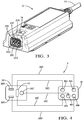
- Figs. 1-7B illustrate a non-limiting example of an electric vehicle supply equipment assembly 10.
- the electric vehicle supply equipment assembly 10 hereinafter referred to as the assembly 10 includes an electronic module 12, hereinafter referred to as the module 12, that contains the electronic circuitry of the EVSE assembly, a first detachable power supply cord 14 that is configured to supply electrical power at about 120 VAC from a socket (not shown) conforming to the National Electrical Manufacturers Association (NEMA) 5-15S technical standard, and a second detachable power supply cord 16 that is configured to supply electrical power at about 240 VAC from a socket (not shown) conforming to the NEMA 6-20S technical standard.
- NEMA National Electrical Manufacturers Association
- about 120 VAC is a voltage in the range of 114 VAC to 126 VAC and is hereinafter referred to as 120 VAC and about 240 VAC is a voltage in the range of 228 VAC to 252 VAC and is hereafter referred to as 240 VAC.
- the module 12 includes a six-way module connector housing 18 in which six round male pin module terminals 20A-20F are disposed.
- the first and second module terminals 20A, 20B are connected to a power supply circuit 22 within the module 12 that converts the 120 VAC or 240 VAC electrical power delivered to the module 12 by the first or second power supply cords 14, 16 to a direct current voltage that is output to the electric vehicle via a power output cord 24 to a coupler (not shown) that is configured to interconnect to the vehicle's charging port (not shown).
- the third module terminal 20C is connected to a power supply ground circuit.
- the fourth and fifth module terminals 20D, 20E are connected to a resistance detection circuit 26 within the module 12 and the sixth module terminal 20F is connected to a voltage detection circuit 28 within the module 12.
- the resistance detection circuit 26 and the voltage detection circuit 28 are both connected to a controller 30 that is configured to control the power supply circuit 22 as will be explained below.
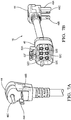
- the first power supply cord 14 has five wire conductors 38A-38E contained within an insulative jacket (not shown), a first plug connector 32 conforming to the NEMA 5-15P technical standard, and a first cord connector housing 34 configured to mate with the six-way module connector housing 18 in which five female socket first cord terminals 40A-40E are disposed.
- the first and second power pin 36A, 36B and a ground pin 36C of the first plug connector 32 conform to the NEMA 5-15P standard and are made of a conductive material, such as a copper alloy.
- the first and second power pin 36A, 36B and the ground pin 36C are interconnected by the first, second and third wire conductors 38A, 38B, 38C of the five wire conductors to the first, second, and third first cord terminals 40A, 40B, 40C respectively. These first cord terminals 40A, 40B, 40C are configured to interconnect with the first, second, and third module terminals 20A, 20B, 20C respectively.
- a first thermistor 42 is disposed within the first plug connector 32 and is interconnected by a fourth and fifth wire connector 38D, 38E to the fourth and fifth first cord terminals 40D, 40E. These terminals are configured to interconnect with the fourth and fifth module terminals 20D, 20E.
- the first thermistor 42 is interconnected to the resistance detection circuit 26 in the module 12. A change in the resistance of the first thermistor 42 indicates a change in the temperature of the first plug connector 32.
- the second power supply cord 16 has five wire conductors 50A-50E contained within an insulative jacket (not shown), a second plug connector 44 conforming to the NEMA 6-20P technical standard, and a six way second cord connector housing 46 configured to mate with the six-way module connector housing 18 in which six female socket second cord terminals 52A-52F are disposed.
- the first and second power pin 48A, 48B and a ground pin 48C of the second plug connector 44 conform to the NEMA 6-20P standard and are made of a conductive material, such as a copper alloy.
- the first and second power pin 48A, 48B and the ground pin 48C of the second plug connector 44 are interconnected by a first, second and third wire conductor 50A, 50B, 50C to a first, second, and third second cord terminal 52A, 52B, 52C respectively. These terminals 52A, 52B, 52C are configured to interconnect with the first, second, and third module terminals 20A, 20B, 20C respectively.
- a second thermistor 54 having the same characteristics and the first thermistor 42 is disposed within the second plug connector 44 and is interconnected by a fourth and fifth wire conductor 50D, 50E to the fourth and fifth second cord terminals 52D, 52E that are configured to interconnect with the fourth and fifth module terminals 20D, 20E.
- a sixth second cord terminal 52F is interconnected to the third second cord terminal 52C by a jumper 50F and is configured to interconnect with the sixth module terminal 20F.
- the controller 30 may include a processor (not shown) such as a microprocessor or other control circuitry as should be evident to those in the art.
- the controller 30 may also include analog to digital convertor circuitry (not shown) and digital to analog convertor circuitry (not shown) to be able to communicate with the resistance detection circuit 26, the voltage detection circuit 28, the power supply circuit 22 and other circuitry (not shown) that may be included in the module 12.
- the controller 30 may also include memory (not shown), including non-volatile memory, such as electrically erasable programmable read-only memory (EEPROM) for storing one or more routines, thresholds and captured data. The one or more routines may be executed by the processor to perform steps for determining the value of the output of the resistance detection circuit 26, the value of the output of the voltage detection circuit 28, and operation of the power supply circuit 22 based on these output values.
- EEPROM electrically erasable programmable read-only memory
- the resistance detection circuit 26 may be a simple voltage divider network and an analog to digital convertor circuit of the controller 30 that is connected to the resistance detection circuit 26 can determine the voltage and provide a digital datum to the controller 30 indicating the value of the voltage and therefore the temperature of the first plug connector 32.
- the controller 30 may be programmed to inhibit operation of the power supply circuit 22 when the temperature of the first plug connector 32 exceeds a threshold temperature.
- the fourth and fifth module terminals 20D, 20E and/or the fourth and fifth cord terminals 40D, 40E, 52D, 52E of the first and second power supply cord 14, 16 may be shorter than the other terminals 20A-C, 20F, 40A-C, 52A-C, 52F and are configured to connect only after the other terminals 20A-C, 20F, 40A-C, 52A-C, 52F have been connected.
- the controller 30 may also be programmed to inhibit operation until a resistance value within an expected range is detected by the resistance detection circuit 26.
- the third module terminal 20C and/or the third cord terminals 40C, 52C may be longer than the other terminals in order to complete a ground circuit prior to the connection of the other circuits.
- the voltage detection circuit 28 may be a simple pull up circuit that is connected to an input of the controller 30.
- the controller 30 configures the power supply circuit 22 to accept 120 VAC electrical power.
- the controller 30 detects ground voltage via the input attached to the voltage, the controller 30 configures the power supply circuit 22 to accept 240 VAC electrical power.
- the first cord connector housing 34 may be a five-way connector housing 34 was shown in Figs. 4 and 5B or it may be a six-way connector housing 46 as shown in Fig. 7B with an empty sixth terminal cavity. While the illustrated examples of the connector housings have connector cavities configured to receive the terminals in a 2 by 3 array, other embodiments may be arranged according to a different configuration, e.g. a 3 by 2 array, a 1 by 6 array or a circular arrangement with terminal cavities spaced at 60 degree intervals. The arrangement and order of the terminals may also be changed in other embodiments.
- the six-way module connector housing 18 and the first and second cord connector housings 34, 46 have corresponding locking features configured to inhibit inadvertent disconnection of the power supply cords from the module 12.
- While the illustrated example shows power supply cords having first and second plug connectors 32, 44 conforming to NEMA 5-15 and 6-20 standards, other embodiments may be envisioned wherein the plug connectors conform to other technical standards, such as Europlug CCE 7/16, British Standard (BS) 1363, Australian/New Zealand Standard AS/NZS 3112, or Chinese PPCS-CCC technical standards.
- other technical standards such as Europlug CCE 7/16, British Standard (BS) 1363, Australian/New Zealand Standard AS/NZS 3112, or Chinese PPCS-CCC technical standards.
- the first and second thermistors 42, 54 are chosen so that they have different initial resistance values.
- the first thermistor 42 may be a negative temperature coefficient (NTC) type thermistor while the second thermistor 54 may be a positive temperature coefficient (PTC) type thermistor.
- NTC negative temperature coefficient
- PTC positive temperature coefficient
- the first thermistor 42 may be selected so that its resistance at normal ambient temperatures is near the highest value in the allowable resistance range and the second thermistor 54 may be selected so that its resistance at normal ambient temperatures is near the lowest value in the allowable resistance range.
- the controller 30 may be configured to determine whether the first or second power supply cord 16 is attached based on the initial thermistor resistance value output by the resistance detection circuit 26. This could be used in place of the voltage detection circuit 28 input or in conjunction with it to improve determination of the power supply circuit's 22 operation.
- an electric vehicle supply equipment assembly 10 having two interchangeable power supply cords 14, 16 is provided.
- the assembly 10 provides the benefit of detecting whether a power supply cord configured to connect with a 120 VAC socket or a 240 VAC socket is connected and automatically configure the module 12 for 120 VAC or 240 VAC operation without any further operator action. This automatic detection prevents damage that may occur to a similar EVSE if an operator changes the power supply cord but does not set the EVSE to the proper operating voltage configuration.
- While the illustrated embodiment is an electrical vehicle supply equipment assembly, other embodiments of this invention may be used for other electrical devices that are configured to be powered by two different voltages supplied by power cords conforming to different technical standards. Still other embodiments of the invention may be envisioned in which the thermistor is not installed within the plug. In these embodiments the associated wire conductors, cord terminals, and module terminals may be deleted.
Landscapes
- Engineering & Computer Science (AREA)
- Microelectronics & Electronic Packaging (AREA)
- Power Engineering (AREA)
- Transportation (AREA)
- Mechanical Engineering (AREA)
- Details Of Connecting Devices For Male And Female Coupling (AREA)
- Electric Propulsion And Braking For Vehicles (AREA)
Abstract
Description
- The invention relates to electric vehicle supply equipment, in particular to electric vehicle supply equipment having multiple interchangeable power supply cords that conform to different technical standards.
- Electric vehicle supply equipment (EVSE) is a portable charging cord set that supplies alternating current (AC) electrical power to on-board battery chargers present in electric vehicles (EVs) or plug-in hybrid electric vehicles (PHEVs). There are many portable charging cord sets available for consumers to purchase and use with their EVs or PHEVs. A typical original equipment manufacturer (OEM) charging cord set used in North America provides a line operating voltage of 120 Volts AC (VAC) to the vehicle and has a grid cord conforming to the National Electrical Manufacturers Association (NEMA) 5-15 standard which is hard-wired to the EVSE. With a line voltage of 120 VAC, it typicality takes 8-10 hours to completely charge the vehicle's battery pack. As newer charging technologies are developed for EVs and PHEVs, some OEMs are requesting a provision for interchangeable grid cords on the EVSE. This approach enables the consumer to either use the 120 VAC grid cord, or remove that cord and replace it with an interchangeable 240 VAC grid cord conforming to the NEMA 6-20 standard that can be used with a 240 VAC input. The 240 VAC option reduces the overall battery charging time by up to 50%.
- The subject matter discussed in the background section should not be assumed to be prior art merely as a result of its mention in the background section. Similarly, a problem mentioned in the background section or associated with the subject matter of the background section should not be assumed to have been previously recognized in the prior art. The subject matter in the background section merely represents different approaches, which in and of themselves may also be inventions.
- In accordance with an embodiment of the invention, an electric vehicle battery charging assembly is provided. The electric vehicle supply equipment includes an electronic module having a six-way module connector housing in which six module terminals are disposed. A first and second module terminals of the six module terminals are connected power supply circuitry within the electronic module. A third module terminal of the six module terminals is connected to a power supply ground circuit. A fourth and fifth module terminals of the six module terminals are connected to a resistance detection circuit within the electronic module. A sixth module terminal of the six module terminals is connected to a voltage detection circuit within the electronic module. The electric vehicle supply equipment further includes a first power supply cord configured to supply electrical power at about 120 VAC from a socket conforming to the National Electrical Manufacturers Association (NEMA) 5-15S technical standard. The first power supply cord has five wire conductors, a first plug connector conforming to the NEMA 5-15P technical standard, and a first cord connector housing that is configured to mate with the six-way module connector housing in which five first cord terminals are disposed. The first cord connector housing may be a five-way or six-way connector housing.
- A first and second power pin and a ground pin of the first plug connector are interconnected by a first, second and third wire conductor of the five wire conductors to a first, second, and third first cord terminals respectively of the five first cord terminals that are configured to interconnect with the first, second, and third module terminals respectively of the six module terminals. A first thermistor is disposed within the first plug connector and is interconnected by a fourth and fifth wire connector to a fourth and fifth first cord terminal of the five first cord terminals that are configured to interconnect with the fourth and fifth module terminals of the six module terminals.
- The electric vehicle supply equipment may further include a second power supply cord that is configured to supply electrical power at about 240 VAC from a socket conforming to the National Electrical Manufacturers Association (NEMA) 6-20S technical standard having five wire conductors, a second plug connector conforming to the NEMA 6-20P technical standard, and a six-way second cord connector housing configured to mate with the six-way module connector housing in which six second cord terminals are disposed. A first and second power pin and a ground pin of the second plug connector are interconnected by a first, second and third wire conductor of the five wire conductors to a first, second, and third second cord terminal respectively of the six second cord terminals that are configured to interconnect with the first, second, and third module terminals respectively of the six module terminals. A second thermistor is disposed within the second plug connector and is interconnected by a fourth and fifth wire connector of the five wire conductors to a fourth and fifth second cord terminal of the six second cord terminals that are configured to interconnect with the fourth and fifth module terminals of the six module terminals. A sixth second cord terminal of the six second cord terminals is interconnected to the third second cord terminal of the six second cord terminals and is configured to interconnect with the sixth module terminal of the six module terminals.
- The electronic module may further include a controller connected to the voltage detection circuit and the controller may be configured to operate the electronic module with an input voltage of about 240 VAC when the voltage detection circuit detects a ground voltage at the sixth module terminal.
- The fourth and fifth module terminals may be shorter than the first, second, third, and sixth module terminals. The fourth and fifth second cord terminals may be shorter than the first, second, third, and sixth second cord terminals.
- The present invention will now be described, by way of example with reference to the accompanying drawings, in which:
-
Fig. 1 is an exploded perspective view of an electric vehicle supply equipment according to one embodiment; -
Fig. 2 is a schematic diagram view of a the electric vehicle supply equipment ofFig. 1 according to one embodiment; -
Fig. 3 is a perspective view of the electric vehicle supply equipment ofFig. 1 according to one embodiment; -
Fig. 4 is a schematic diagram view of a first power supply cord of the electric vehicle supply equipment ofFig. 1 according to one embodiment; -
Fig. 5A is a close up view of a plug connector of the first power supply cord of the electric vehicle supply equipment ofFig. 1 according to one embodiment; -
Fig. 5B is a close up view of a cord connector of the first power supply cord of the electric vehicle supply equipment ofFig. 1 according to one embodiment; -
Fig. 6 is a schematic diagram view of a second power supply cord of the electric vehicle supply equipment ofFig. 1 according to one embodiment; -
Fig. 7A is a close up view of a plug connector of the second power supply cord of the electric vehicle supply equipment ofFig. 1 according to one embodiment; and -
Fig. 7B is a close up view of a cord connector of the second power supply cord of the electric vehicle supply equipment ofFig. 1 according to one embodiment. - An electric vehicle supply equipment (EVSE) assembly for an electric vehicle (EV) or plug-in hybrid electric vehicle (PHEV), is presented herein. The electric vehicle supply equipment assembly optionally has one of at least two interchangeable power supply cords with plugs that conform to different technical standards, such as National Electrical Manufacturers Association (NEMA) 5-15P or 6-20P. The interchangeable power supply cord plugs each include a thermistor adapted to monitor plug temperatures. The EVSE assembly is configured to disable charging until a proper resistance of the thermistor in the plug is detected, thereby indicating the plug is within an acceptable temperature range. The EVSE assembly is also configured to detect ground circuit faults and current overvoltage conditions, providing additional circuit protection to that provided by the grid supply circuit. The EVSE assembly is further configured to automatically switch between 120 volt and 240 volt operation based on which of the interchangeable power supply cords is connected to the EVSE.
- Although the disclosure hereof is detailed and exact to enable those skilled in the art to practice the invention, the physical embodiments herein disclosed merely exemplify the invention which may be embodied in other specific structures. While a preferred embodiment has been described, the details may be changed without departing from the invention. A description of example embodiments of the invention follows.
-
Figs. 1-7B illustrate a non-limiting example of an electric vehiclesupply equipment assembly 10. As shown inFig. 1 , the electric vehiclesupply equipment assembly 10, hereinafter referred to as theassembly 10, includes anelectronic module 12, hereinafter referred to as themodule 12, that contains the electronic circuitry of the EVSE assembly, a first detachablepower supply cord 14 that is configured to supply electrical power at about 120 VAC from a socket (not shown) conforming to the National Electrical Manufacturers Association (NEMA) 5-15S technical standard, and a second detachablepower supply cord 16 that is configured to supply electrical power at about 240 VAC from a socket (not shown) conforming to the NEMA 6-20S technical standard. As used herein, about 120 VAC is a voltage in the range of 114 VAC to 126 VAC and is hereinafter referred to as 120 VAC and about 240 VAC is a voltage in the range of 228 VAC to 252 VAC and is hereafter referred to as 240 VAC. - As shown in
Figs. 2 and3 , themodule 12 includes a six-waymodule connector housing 18 in which six round malepin module terminals 20A-20F are disposed. The first andsecond module terminals power supply circuit 22 within themodule 12 that converts the 120 VAC or 240 VAC electrical power delivered to themodule 12 by the first or secondpower supply cords power output cord 24 to a coupler (not shown) that is configured to interconnect to the vehicle's charging port (not shown). Thethird module terminal 20C is connected to a power supply ground circuit. The fourth andfifth module terminals resistance detection circuit 26 within themodule 12 and thesixth module terminal 20F is connected to avoltage detection circuit 28 within themodule 12. Theresistance detection circuit 26 and thevoltage detection circuit 28 are both connected to acontroller 30 that is configured to control thepower supply circuit 22 as will be explained below. - As shown in
Figs 4 ,5A, and 5B , the firstpower supply cord 14 has fivewire conductors 38A-38E contained within an insulative jacket (not shown), afirst plug connector 32 conforming to the NEMA 5-15P technical standard, and a firstcord connector housing 34 configured to mate with the six-waymodule connector housing 18 in which five female socketfirst cord terminals 40A-40E are disposed. The first andsecond power pin ground pin 36C of thefirst plug connector 32 conform to the NEMA 5-15P standard and are made of a conductive material, such as a copper alloy. The first andsecond power pin ground pin 36C are interconnected by the first, second andthird wire conductors first cord terminals first cord terminals third module terminals first thermistor 42 is disposed within thefirst plug connector 32 and is interconnected by a fourth andfifth wire connector first cord terminals fifth module terminals first thermistor 42 is interconnected to theresistance detection circuit 26 in themodule 12. A change in the resistance of thefirst thermistor 42 indicates a change in the temperature of thefirst plug connector 32. - As shown in
Figs 6 ,7A, and 7B , the secondpower supply cord 16 has fivewire conductors 50A-50E contained within an insulative jacket (not shown), asecond plug connector 44 conforming to the NEMA 6-20P technical standard, and a six way secondcord connector housing 46 configured to mate with the six-waymodule connector housing 18 in which six female socketsecond cord terminals 52A-52F are disposed. The first andsecond power pin ground pin 48C of thesecond plug connector 44 conform to the NEMA 6-20P standard and are made of a conductive material, such as a copper alloy. The first andsecond power pin ground pin 48C of thesecond plug connector 44 are interconnected by a first, second andthird wire conductor second cord terminal terminals third module terminals second thermistor 54 having the same characteristics and thefirst thermistor 42 is disposed within thesecond plug connector 44 and is interconnected by a fourth andfifth wire conductor second cord terminals fifth module terminals second cord terminal 52F is interconnected to the thirdsecond cord terminal 52C by ajumper 50F and is configured to interconnect with thesixth module terminal 20F. - The
controller 30 may include a processor (not shown) such as a microprocessor or other control circuitry as should be evident to those in the art. Thecontroller 30 may also include analog to digital convertor circuitry (not shown) and digital to analog convertor circuitry (not shown) to be able to communicate with theresistance detection circuit 26, thevoltage detection circuit 28, thepower supply circuit 22 and other circuitry (not shown) that may be included in themodule 12. Thecontroller 30 may also include memory (not shown), including non-volatile memory, such as electrically erasable programmable read-only memory (EEPROM) for storing one or more routines, thresholds and captured data. The one or more routines may be executed by the processor to perform steps for determining the value of the output of theresistance detection circuit 26, the value of the output of thevoltage detection circuit 28, and operation of thepower supply circuit 22 based on these output values. - The
resistance detection circuit 26 may be a simple voltage divider network and an analog to digital convertor circuit of thecontroller 30 that is connected to theresistance detection circuit 26 can determine the voltage and provide a digital datum to thecontroller 30 indicating the value of the voltage and therefore the temperature of thefirst plug connector 32. Thecontroller 30 may be programmed to inhibit operation of thepower supply circuit 22 when the temperature of thefirst plug connector 32 exceeds a threshold temperature. - The fourth and
fifth module terminals fifth cord terminals power supply cord other terminals 20A-C, 20F, 40A-C, 52A-C, 52F and are configured to connect only after theother terminals 20A-C, 20F, 40A-C, 52A-C, 52F have been connected. Thecontroller 30 may also be programmed to inhibit operation until a resistance value within an expected range is detected by theresistance detection circuit 26. In addition, thethird module terminal 20C and/or thethird cord terminals - The
voltage detection circuit 28 may be a simple pull up circuit that is connected to an input of thecontroller 30. When the firstpower supply cord 14 is connected to themodule 12, the voltage on thesixth module terminal 20F is at the pull up voltage and thecontroller 30 configures thepower supply circuit 22 to accept 120 VAC electrical power. However, when the secondpower supply cord 16 is attached thesixth module terminal 20F is at ground voltage due to the interconnection of the third and sixthsecond cord terminals controller 30 detects ground voltage via the input attached to the voltage, thecontroller 30 configures thepower supply circuit 22 to accept 240 VAC electrical power. - The first
cord connector housing 34 may be a five-way connector housing 34 was shown inFigs. 4 and5B or it may be a six-way connector housing 46 as shown inFig. 7B with an empty sixth terminal cavity. While the illustrated examples of the connector housings have connector cavities configured to receive the terminals in a 2 by 3 array, other embodiments may be arranged according to a different configuration, e.g. a 3 by 2 array, a 1 by 6 array or a circular arrangement with terminal cavities spaced at 60 degree intervals. The arrangement and order of the terminals may also be changed in other embodiments. - As shown in
Figs. 3 ,5B and7B , the six-waymodule connector housing 18 and the first and secondcord connector housings module 12. - While the illustrated example shows power supply cords having first and
second plug connectors - In an alternative embodiment, the first and
second thermistors first thermistor 42 may be a negative temperature coefficient (NTC) type thermistor while thesecond thermistor 54 may be a positive temperature coefficient (PTC) type thermistor. Thefirst thermistor 42 may be selected so that its resistance at normal ambient temperatures is near the highest value in the allowable resistance range and thesecond thermistor 54 may be selected so that its resistance at normal ambient temperatures is near the lowest value in the allowable resistance range. Thecontroller 30 may be configured to determine whether the first or secondpower supply cord 16 is attached based on the initial thermistor resistance value output by theresistance detection circuit 26. This could be used in place of thevoltage detection circuit 28 input or in conjunction with it to improve determination of the power supply circuit's 22 operation. - Therefore an electric vehicle
supply equipment assembly 10 having two interchangeablepower supply cords assembly 10 provides the benefit of detecting whether a power supply cord configured to connect with a 120 VAC socket or a 240 VAC socket is connected and automatically configure themodule 12 for 120 VAC or 240 VAC operation without any further operator action. This automatic detection prevents damage that may occur to a similar EVSE if an operator changes the power supply cord but does not set the EVSE to the proper operating voltage configuration. - While the illustrated embodiment is an electrical vehicle supply equipment assembly, other embodiments of this invention may be used for other electrical devices that are configured to be powered by two different voltages supplied by power cords conforming to different technical standards. Still other embodiments of the invention may be envisioned in which the thermistor is not installed within the plug. In these embodiments the associated wire conductors, cord terminals, and module terminals may be deleted.
- While this invention has been described in terms of the preferred embodiments thereof, it is not intended to be so limited, but rather only to the extent set forth in the claims that follow. Moreover, the use of the terms first, second, etc. does not denote any order of importance, but rather the terms first, second, etc. are used to distinguish one element from another. Furthermore, the use of the terms a, an, etc. do not denote a limitation of quantity, but rather denote the presence of at least one of the referenced items.
Claims (14)
- An electric vehicle supply equipment (10), comprising:an electronic module (12) having a six-way module connector housing (18) in which six module terminals (20A-F) are disposed, wherein a first and second module terminal (20A, 20B) of said six module terminals (20A-F) are connected to power supply circuitry within the electronic module (12), wherein a third module terminal (20C) of said six module terminals (20A-F) is connected to a power supply ground circuit, wherein a fourth and fifth module terminal (20D, 20E) of said six module terminals (20A-F) are connected to a resistance detection circuit (26) within the electronic module (12), and wherein a sixth module terminal (20F) of said six module terminals (20A-F) is connected to a voltage detection circuit (28) within the electronic module (12);a first power supply cord (14) configured to supply electrical power at about 120 VAC from a socket conforming to the National Electrical Manufacturers Association (NEMA) 5-15S technical standard having five wire conductors (38A-E), a first plug connector (32) conforming to the NEMA 5-15P technical standard, and a first cord connector housing (34) configured to mate with the six-way module connector housing (18) in which five first cord terminals (40A-E) are disposed, wherein a first and second power pin (36A, 36B) and a ground pin (36C) of the first plug connector (32) are interconnected by a first, second and third wire conductor (38A, 38B, 38C) of said five wire conductors (38A-E) to a first, second, and third first cord terminal (40A, 40B, 40C) respectively of said five first cord terminals (40A-F) that are configured to interconnect with the first, second, and third module terminals (20A, 20B, 20C) respectively of said six module terminals (20A-F), and wherein a first thermistor (42) is disposed within the first plug connector (32) and is interconnected by a fourth and fifth wire connector (38D, 38E) to a fourth and fifth first cord terminal (40D, 40E) of said five first cord terminals (40A-E) that are configured to interconnect with the fourth and fifth module terminals (20D, 20E) of said six module terminals (20A-F).
- The electric vehicle supply equipment (10) according to claim 1, further comprising a second power supply cord (16) configured to supply electrical power at about 240 VAC from a socket conforming to the NEMA 6-20S technical standard having five wire conductors (50A-50E), a second plug connector (44) conforming to the NEMA 6-20P technical standard, and six-way second cord connector housing (46) configured to mate with the six-way module connector housing (18) in which six second cord terminals (52A-52F) are disposed, wherein a first and second power pin (48A, 48B) and a ground pin (48C) of the second plug connector (44) are interconnected by a first, second and third wire conductor (50A, 50B, 50C) of said five wire conductors (50a-e) to a first, second, and third second cord terminal (52A, 52B, 52C) respectively of said six second cord terminals (52A-F) that are configured to interconnect with the first, second, and third module terminals (20A, 20B, 20C) respectively of said six module terminals (20A-F), wherein a second thermistor (54) is disposed within the second plug connector (44) and is interconnected by a fourth and fifth wire connector (50D, 50E) of said five wire conductors (50A-E) to a fourth and fifth second cord terminal (52D, 52E) of said six second cord terminals (52A-F) that are configured to interconnect with the fourth and fifth module terminals (20D, 20E) of said six module terminals (20A-F), wherein a sixth second cord terminal (52F) of said six second cord terminals (52A-F) is interconnected to the third second cord terminal (52C) of said six second cord terminals (52A-F) and is configured to interconnect with the sixth module terminal (20F) of said six module terminals (20A-F).
- The electric vehicle supply equipment (10) according to claim 2, wherein the fourth and fifth second cord terminals (52D, 52E) are shorter than the first, second, third, and sixth second cord terminals (52A, 52B, 52C, 52F).
- The electric vehicle supply equipment (10) according to one of the claims 1-3, wherein the electronic module (12) further includes a controller (30) connected to the voltage detection circuit (28) and wherein the controller (30) is configured to operate the electronic module (12) with an input voltage of about 240 VAC when the voltage detection circuit (28) detects a ground voltage at the sixth module terminal (20F).
- The electric vehicle supply equipment (10) according to one of the claims 1-4, wherein the fourth and fifth module terminals (20D, 20D) are shorter than the first, second, third, and sixth module terminals (20A, 20B, 20C, 20F).
- The electric vehicle supply equipment (10) according to one of the claims 1-5, wherein the fourth and fifth first cord terminals (40D, 40E) are shorter than the first, second, and third first cord terminals (40A, 40B, 40C).
- The electric vehicle supply equipment (10) according to one of the claims 1-6, wherein the first cord connector housing (34) is a five-way connector housing (34).
- The electric vehicle supply equipment (10) according to one of the claims 1-7, wherein the first cord connector housing (34) is a six-way connector housing (46).
- A power supply cord (14) configured to supply electrical power at about 120 VAC from a socket conforming to the 5-15S technical standard to an electronic module (12) having a six-way module connector housing (18) in which six module terminals (20A-F) are disposed, wherein a first and second module terminals (20A, 20B) of said six module terminals (20A-F) are connected to power supply circuitry within the electronic module (12), wherein a third module terminal (20C) of said six module terminals (20A-F) is connected to a power supply ground circuit, wherein a fourth and fifth module terminals (20D, 20E) of said six module terminals (20A-F) are connected to a resistance detection circuit (26) within the electronic module (12), and wherein a wherein a sixth module terminal (20F) of said six module terminals (20A) is connected to a voltage detection circuit (28) within the electronic module (12), said power supply cord (14) comprising:five wire conductors (38A-E);a plug connector (32) conforming to the NEMA 5-15P technical standard;a cord connector housing (34) configured to mate with the six-way module connector housing (18); andfive cord terminals (40A-E) disposed within the cord connector housing (34), wherein a first and second power pin (36A, 36B) and a ground pin (36C) of the plug connector (32) are interconnected by a first, second and third wire conductor (38A, 38B, 38C) of said five wire conductors (38A-E) to a first, second, and third cord terminal (40A, 40B, 40C) respectively of said five cord terminals (40A-E) that are configured to interconnect with the first, second, and third module terminals (20A, 20B, 20C) respectively of said six module terminals (20A-F), and wherein a thermistor (42) is disposed within the plug connector (32) and is interconnected by a fourth and fifth wire connector (38D, 38E) to a fourth and fifth cord terminals (40D, 40E) of said five cord terminals (40A-E) that are configured to interconnect with the fourth and fifth module terminals (20D, 20E) of said six module terminals (20A-F).
- The power supply cord (14) according to claim 9, wherein the fourth and fifth cord terminals (40D, 40E) are shorter than the first, second, and third first cord terminals (40A, 40B, 40C).
- The power supply cord (14) according to one of the claims 9-10, wherein the first cord connector housing (34) is a five-way connector housing (34).
- The power supply cord (14) according to one of the claims 9-11, wherein the first cord connector housing (34) is a six-way connector housing (46).
- A power supply cord (16) configured to supply electrical power at about 240 VAC from a socket conforming to the 6-20S technical standard to an electronic module (12) having a six-way module connector housing (18) in which six module terminals (20A-F) are disposed, wherein a first and second module terminals (20A, 20B) of said six module terminals (20A-F) are connected power supply circuitry within the electronic module (12), wherein a third module terminal (20C) of said six module terminals (20A-F) is connected to a power supply ground circuit, wherein a fourth and fifth module terminals (20D, 20E) of said six module terminals (20A-F) are connected to a resistance detection circuit (26) within the electronic module (12), and wherein a wherein a sixth module terminal (20F) of said six module terminals (20A-F) is connected to a voltage detection circuit (28) within the electronic module (12), said power supply cord (16) comprising:five wire conductors (50A-E);a plug connector (44) conforming to the NEMA 6-20P technical standard;a six way cord connector housing (46) configured to mate with the six-way module connector housing (18); andsix cord terminals (512A-F) within the cord connector housing (46),wherein a first and second power pin (48A, 48B) and a ground pin (48C) of the plug connector (44) are interconnected by a first, second and third wire conductor (50A, 50B, 50C) of said five wire conductors (50A-E) to a first, second, and third cord terminals (52A, 52B, 52C) respectively of said six cord terminals (52A-F) that are configured to interconnect with the first, second, and third module terminals (20A, 20B, 20C) respectively of said six module terminals (20A-F), wherein a thermistor (54) is disposed within the plug connector (44) and is interconnected by a fourth and fifth wire conductor 950D, 50E) of said five wire conductors (50A-E) to a fourth and fifth cord terminals (52D, 52E) of said six cord terminals (52A-F) that are configured to interconnect with the fourth and fifth module terminals (20D, 20E) of said six module terminals (20A-F), wherein a sixth cord terminal (52F) of said six cord terminals (52A-F) is interconnected to the third cord terminal (52C) of said six second cord terminals (52A-F) and is configured to interconnect with the sixth module terminal (20F) of said six module terminals (20A-F).
- The power supply cord (16) according to claim 13, wherein the fourth and fifth cord terminals (52D, 52E) are shorter than the first, second and third cord terminals (52A, 52B, 52C).
Applications Claiming Priority (1)
| Application Number | Priority Date | Filing Date | Title |
|---|---|---|---|
| US15/159,278 US9634435B1 (en) | 2016-05-19 | 2016-05-19 | Electric vehicle power supply equipment with interchangeable power supply cords conforming to different technical standards |
Publications (1)
| Publication Number | Publication Date |
|---|---|
| EP3246198A1 true EP3246198A1 (en) | 2017-11-22 |
Family
ID=58547222
Family Applications (1)
| Application Number | Title | Priority Date | Filing Date |
|---|---|---|---|
| EP17171163.3A Withdrawn EP3246198A1 (en) | 2016-05-19 | 2017-05-15 | Electric vehicle supply equipment with interchangeable power supply cords conforming to different technical standards |
Country Status (2)
| Country | Link |
|---|---|
| US (1) | US9634435B1 (en) |
| EP (1) | EP3246198A1 (en) |
Cited By (2)
| Publication number | Priority date | Publication date | Assignee | Title |
|---|---|---|---|---|
| CN107399243A (en) * | 2017-06-08 | 2017-11-28 | 江苏维科新能源科技有限公司 | A kind of battery harvester based on FPC soft arranging wires |
| CN110401075A (en) * | 2018-04-25 | 2019-11-01 | 矢崎总业株式会社 | charging connector |
Families Citing this family (17)
| Publication number | Priority date | Publication date | Assignee | Title |
|---|---|---|---|---|
| WO2017138939A1 (en) * | 2016-02-11 | 2017-08-17 | Lear Corporation | Vehicle charge-cord system |
| USD825568S1 (en) * | 2017-02-07 | 2018-08-14 | Idsc Holdings, Llc | Dual-connector wireless vehicle communication interface |
| USD806040S1 (en) * | 2017-02-07 | 2017-12-26 | Snap-On Incorporated | Dual-connector wireless vehicle communication interface |
| USD828838S1 (en) * | 2017-02-07 | 2018-09-18 | Idsc Holdings, Llc | Dual-connector wireless vehicle communication interface |
| US10393045B2 (en) | 2017-02-07 | 2019-08-27 | Idsc Holdings, Llc | Method and system for initiating regeneration of diesel particulate filters |
| CN109428245B (en) * | 2017-09-04 | 2020-06-16 | 芯籁半导体股份有限公司 | a charging cable |
| JP7395493B2 (en) * | 2018-03-28 | 2023-12-11 | デックスコム・インコーポレーテッド | Sensor cable support device including mechanical connectors |
| US10446979B1 (en) * | 2018-07-18 | 2019-10-15 | Prodigit Electronics Co., Ltd. | Power plug adapter with magnetically attachable module |
| US11506541B2 (en) * | 2019-01-03 | 2022-11-22 | Aptiv Technologies Limited | Temperature monitoring device |
| US11705680B2 (en) * | 2020-05-27 | 2023-07-18 | Drew Syingshun Liu | Wall-mounted electrical-connector-engaging assembly with quick installation features |
| CN112003052B (en) * | 2020-08-24 | 2021-07-20 | 东风汽车集团有限公司 | A multi-channel high-voltage electrical connector and a new energy vehicle |
| US12062869B2 (en) | 2020-12-18 | 2024-08-13 | Webasto Charging Systems, Inc. | Electrical connector assembly |
| CN112959907B (en) * | 2021-04-13 | 2022-03-18 | 东营科技职业学院 | Portable rifle that charges of car new forms of energy |
| US11688985B2 (en) * | 2021-05-07 | 2023-06-27 | Cummins Inc. | Electrical interconnect system for an electric vehicle |
| KR102898361B1 (en) | 2021-09-14 | 2025-12-09 | 현대자동차주식회사 | Control-box-deteachable charging cables |
| US12187145B2 (en) | 2021-09-24 | 2025-01-07 | Aptiv Technologies AG | Electric vehicle supply equipment power supply cord |
| US12597742B2 (en) | 2022-09-23 | 2026-04-07 | Aptiv Technologies AG | Electric vehicle supply equipment and power cord |
Citations (5)
| Publication number | Priority date | Publication date | Assignee | Title |
|---|---|---|---|---|
| JP2012135104A (en) * | 2010-12-21 | 2012-07-12 | Toyota Motor Corp | Charging connection device |
| WO2014036013A2 (en) * | 2012-08-27 | 2014-03-06 | Aerovironment, Inc. | Portable electric vehicle supply equipment |
| US20150035483A1 (en) * | 2013-08-01 | 2015-02-05 | Lear Corporation | Electrical cable assembly for electric vehicle |
| US20160059719A1 (en) * | 2014-09-01 | 2016-03-03 | Lsis Co., Ltd. | Vehicle charging device and method |
| EP3000647A2 (en) * | 2014-09-01 | 2016-03-30 | LSIS Co., Ltd. | Vehicle charging device and method |
Family Cites Families (13)
| Publication number | Priority date | Publication date | Assignee | Title |
|---|---|---|---|---|
| US5125854A (en) * | 1991-07-16 | 1992-06-30 | Molex Incorporated | Modular electrical connector |
| US6368155B1 (en) * | 1999-07-16 | 2002-04-09 | Molex Incorporated | Intelligent sensing connectors |
| DE202010006401U1 (en) * | 2010-05-04 | 2011-10-12 | Brose Fahrzeugteile GmbH & Co. Kommanditgesellschaft, Würzburg | Electrical module connection of a motor vehicle |
| KR20120025837A (en) * | 2010-09-08 | 2012-03-16 | 엘에스전선 주식회사 | Connector for charging an electric car |
| US8202124B1 (en) * | 2011-03-11 | 2012-06-19 | Lear Corporation | Contact and receptacle assembly for a vehicle charging inlet |
| JP5673309B2 (en) * | 2011-04-05 | 2015-02-18 | 住友電装株式会社 | Vehicle side connector |
| US8668506B2 (en) * | 2011-04-27 | 2014-03-11 | Lear Corporation | Charger receptacle |
| JP5813462B2 (en) * | 2011-10-31 | 2015-11-17 | 矢崎総業株式会社 | Connector mating structure |
| US8708745B2 (en) * | 2011-11-07 | 2014-04-29 | Apple Inc. | Dual orientation electronic connector |
| JP5981294B2 (en) * | 2012-10-12 | 2016-08-31 | 矢崎総業株式会社 | Charging inlet device |
| US8986030B2 (en) * | 2012-12-06 | 2015-03-24 | Phoenix Contact Development and Manufacturing, Inc. | Modular electric power distribution system |
| CN105075026B (en) * | 2013-03-19 | 2017-10-24 | 住友电装株式会社 | Vehicle-side connector |
| US9543696B2 (en) * | 2014-02-06 | 2017-01-10 | Peterson Manufacturing Company | Quick replacement connector |
-
2016
- 2016-05-19 US US15/159,278 patent/US9634435B1/en active Active
-
2017
- 2017-05-15 EP EP17171163.3A patent/EP3246198A1/en not_active Withdrawn
Patent Citations (5)
| Publication number | Priority date | Publication date | Assignee | Title |
|---|---|---|---|---|
| JP2012135104A (en) * | 2010-12-21 | 2012-07-12 | Toyota Motor Corp | Charging connection device |
| WO2014036013A2 (en) * | 2012-08-27 | 2014-03-06 | Aerovironment, Inc. | Portable electric vehicle supply equipment |
| US20150035483A1 (en) * | 2013-08-01 | 2015-02-05 | Lear Corporation | Electrical cable assembly for electric vehicle |
| US20160059719A1 (en) * | 2014-09-01 | 2016-03-03 | Lsis Co., Ltd. | Vehicle charging device and method |
| EP3000647A2 (en) * | 2014-09-01 | 2016-03-30 | LSIS Co., Ltd. | Vehicle charging device and method |
Cited By (3)
| Publication number | Priority date | Publication date | Assignee | Title |
|---|---|---|---|---|
| CN107399243A (en) * | 2017-06-08 | 2017-11-28 | 江苏维科新能源科技有限公司 | A kind of battery harvester based on FPC soft arranging wires |
| CN107399243B (en) * | 2017-06-08 | 2020-05-05 | 江苏维科新能源科技有限公司 | Battery collection system based on FPC soft arranging wire |
| CN110401075A (en) * | 2018-04-25 | 2019-11-01 | 矢崎总业株式会社 | charging connector |
Also Published As
| Publication number | Publication date |
|---|---|
| US9634435B1 (en) | 2017-04-25 |
Similar Documents
| Publication | Publication Date | Title |
|---|---|---|
| EP3246198A1 (en) | Electric vehicle supply equipment with interchangeable power supply cords conforming to different technical standards | |
| US9490640B2 (en) | Temperature monitoring HEV charger cord assembly and charging method | |
| US11309724B2 (en) | Battery connection method and apparatus | |
| KR101587356B1 (en) | Recharging device and recharging method for vehicle | |
| US6905362B2 (en) | Electric vehicle battery rapid charging connector | |
| CN104901080B (en) | Wall plug system for electric vehicle | |
| EP2990255A1 (en) | Vehicle charging device and method | |
| US7944667B2 (en) | Thermal security for hybrid vehicle recharging cable plugs device and method | |
| EP3960528A1 (en) | Standalone or networked electric vehicle supply equipment (evse) to detect and stop arcing before it becomes dangerous | |
| CN105610124B (en) | EVSE handle with automatic thermal shut-off through NTC to ground | |
| DE102015206840B4 (en) | Thermally monitored charging device | |
| US20190375299A1 (en) | Dual temperature-monitoring hev charger cord and adapter assembly | |
| US12055444B2 (en) | Temperature monitoring device | |
| US9707846B2 (en) | Connection system | |
| EP3166187B1 (en) | Adaptable electrical plug assembly | |
| CN108701984B (en) | Ground overcurrent control system and method of using ground overcurrent control system | |
| WO2013087482A1 (en) | Connector with indicator body and separation device mountable to a cable | |
| US10446974B2 (en) | Electrical connector having an arc suppression element | |
| CN114586210A (en) | Battery module | |
| CN105980195A (en) | System for managing the recharge of an electric or hybrid vehicle | |
| US20140361729A1 (en) | Devices, Systems and Methods for Mining Equipment | |
| WO2022215154A1 (en) | In-vehicle feed system |
Legal Events
| Date | Code | Title | Description |
|---|---|---|---|
| PUAI | Public reference made under article 153(3) epc to a published international application that has entered the european phase |
Free format text: ORIGINAL CODE: 0009012 |
|
| AK | Designated contracting states |
Kind code of ref document: A1 Designated state(s): AL AT BE BG CH CY CZ DE DK EE ES FI FR GB GR HR HU IE IS IT LI LT LU LV MC MK MT NL NO PL PT RO RS SE SI SK SM TR |
|
| AX | Request for extension of the european patent |
Extension state: BA ME |
|
| 17P | Request for examination filed |
Effective date: 20180522 |
|
| RBV | Designated contracting states (corrected) |
Designated state(s): AL AT BE BG CH CY CZ DE DK EE ES FI FR GB GR HR HU IE IS IT LI LT LU LV MC MK MT NL NO PL PT RO RS SE SI SK SM TR |
|
| RAP1 | Party data changed (applicant data changed or rights of an application transferred) |
Owner name: APTIV TECHNOLOGIES LIMITED |
|
| 17Q | First examination report despatched |
Effective date: 20190426 |
|
| STAA | Information on the status of an ep patent application or granted ep patent |
Free format text: STATUS: THE APPLICATION IS DEEMED TO BE WITHDRAWN |
|
| 18D | Application deemed to be withdrawn |
Effective date: 20190907 |