EP3246063A1 - Nasal cannula - Google Patents
Nasal cannula Download PDFInfo
- Publication number
- EP3246063A1 EP3246063A1 EP16183417.1A EP16183417A EP3246063A1 EP 3246063 A1 EP3246063 A1 EP 3246063A1 EP 16183417 A EP16183417 A EP 16183417A EP 3246063 A1 EP3246063 A1 EP 3246063A1
- Authority
- EP
- European Patent Office
- Prior art keywords
- gas
- nasal
- patient
- flow
- sensing module
- Prior art date
- Legal status (The legal status is an assumption and is not a legal conclusion. Google has not performed a legal analysis and makes no representation as to the accuracy of the status listed.)
- Granted
Links
Images






Classifications
-
- A—HUMAN NECESSITIES
- A61—MEDICAL OR VETERINARY SCIENCE; HYGIENE
- A61M—DEVICES FOR INTRODUCING MEDIA INTO, OR ONTO, THE BODY; DEVICES FOR TRANSDUCING BODY MEDIA OR FOR TAKING MEDIA FROM THE BODY; DEVICES FOR PRODUCING OR ENDING SLEEP OR STUPOR
- A61M16/00—Devices for influencing the respiratory system of patients by gas treatment, e.g. ventilators; Tracheal tubes
- A61M16/06—Respiratory or anaesthetic masks
- A61M16/0666—Nasal cannulas or tubing
-
- A—HUMAN NECESSITIES
- A61—MEDICAL OR VETERINARY SCIENCE; HYGIENE
- A61B—DIAGNOSIS; SURGERY; IDENTIFICATION
- A61B5/00—Measuring for diagnostic purposes; Identification of persons
- A61B5/08—Measuring devices for evaluating the respiratory organs
-
- A—HUMAN NECESSITIES
- A61—MEDICAL OR VETERINARY SCIENCE; HYGIENE
- A61M—DEVICES FOR INTRODUCING MEDIA INTO, OR ONTO, THE BODY; DEVICES FOR TRANSDUCING BODY MEDIA OR FOR TAKING MEDIA FROM THE BODY; DEVICES FOR PRODUCING OR ENDING SLEEP OR STUPOR
- A61M16/00—Devices for influencing the respiratory system of patients by gas treatment, e.g. ventilators; Tracheal tubes
- A61M16/0051—Devices for influencing the respiratory system of patients by gas treatment, e.g. ventilators; Tracheal tubes with alarm devices
-
- A—HUMAN NECESSITIES
- A61—MEDICAL OR VETERINARY SCIENCE; HYGIENE
- A61M—DEVICES FOR INTRODUCING MEDIA INTO, OR ONTO, THE BODY; DEVICES FOR TRANSDUCING BODY MEDIA OR FOR TAKING MEDIA FROM THE BODY; DEVICES FOR PRODUCING OR ENDING SLEEP OR STUPOR
- A61M16/00—Devices for influencing the respiratory system of patients by gas treatment, e.g. ventilators; Tracheal tubes
- A61M16/08—Bellows; Connecting tubes ; Water traps; Patient circuits
- A61M16/0816—Joints or connectors
- A61M16/0841—Joints or connectors for sampling
- A61M16/0858—Pressure sampling ports
-
- A—HUMAN NECESSITIES
- A61—MEDICAL OR VETERINARY SCIENCE; HYGIENE
- A61M—DEVICES FOR INTRODUCING MEDIA INTO, OR ONTO, THE BODY; DEVICES FOR TRANSDUCING BODY MEDIA OR FOR TAKING MEDIA FROM THE BODY; DEVICES FOR PRODUCING OR ENDING SLEEP OR STUPOR
- A61M16/00—Devices for influencing the respiratory system of patients by gas treatment, e.g. ventilators; Tracheal tubes
- A61M16/0003—Accessories therefor, e.g. sensors, vibrators, negative pressure
- A61M2016/0027—Accessories therefor, e.g. sensors, vibrators, negative pressure pressure meter
-
- A—HUMAN NECESSITIES
- A61—MEDICAL OR VETERINARY SCIENCE; HYGIENE
- A61M—DEVICES FOR INTRODUCING MEDIA INTO, OR ONTO, THE BODY; DEVICES FOR TRANSDUCING BODY MEDIA OR FOR TAKING MEDIA FROM THE BODY; DEVICES FOR PRODUCING OR ENDING SLEEP OR STUPOR
- A61M16/00—Devices for influencing the respiratory system of patients by gas treatment, e.g. ventilators; Tracheal tubes
- A61M16/0003—Accessories therefor, e.g. sensors, vibrators, negative pressure
- A61M2016/003—Accessories therefor, e.g. sensors, vibrators, negative pressure with a flowmeter
- A61M2016/0033—Accessories therefor, e.g. sensors, vibrators, negative pressure with a flowmeter electrical
- A61M2016/0036—Accessories therefor, e.g. sensors, vibrators, negative pressure with a flowmeter electrical in the breathing tube and used in both inspiratory and expiratory phase
-
- A—HUMAN NECESSITIES
- A61—MEDICAL OR VETERINARY SCIENCE; HYGIENE
- A61M—DEVICES FOR INTRODUCING MEDIA INTO, OR ONTO, THE BODY; DEVICES FOR TRANSDUCING BODY MEDIA OR FOR TAKING MEDIA FROM THE BODY; DEVICES FOR PRODUCING OR ENDING SLEEP OR STUPOR
- A61M2202/00—Special media to be introduced, removed or treated
- A61M2202/0007—Special media to be introduced, removed or treated introduced into the body
-
- A—HUMAN NECESSITIES
- A61—MEDICAL OR VETERINARY SCIENCE; HYGIENE
- A61M—DEVICES FOR INTRODUCING MEDIA INTO, OR ONTO, THE BODY; DEVICES FOR TRANSDUCING BODY MEDIA OR FOR TAKING MEDIA FROM THE BODY; DEVICES FOR PRODUCING OR ENDING SLEEP OR STUPOR
- A61M2202/00—Special media to be introduced, removed or treated
- A61M2202/02—Gases
- A61M2202/0208—Oxygen
-
- A—HUMAN NECESSITIES
- A61—MEDICAL OR VETERINARY SCIENCE; HYGIENE
- A61M—DEVICES FOR INTRODUCING MEDIA INTO, OR ONTO, THE BODY; DEVICES FOR TRANSDUCING BODY MEDIA OR FOR TAKING MEDIA FROM THE BODY; DEVICES FOR PRODUCING OR ENDING SLEEP OR STUPOR
- A61M2202/00—Special media to be introduced, removed or treated
- A61M2202/02—Gases
- A61M2202/0225—Carbon oxides, e.g. Carbon dioxide
-
- A—HUMAN NECESSITIES
- A61—MEDICAL OR VETERINARY SCIENCE; HYGIENE
- A61M—DEVICES FOR INTRODUCING MEDIA INTO, OR ONTO, THE BODY; DEVICES FOR TRANSDUCING BODY MEDIA OR FOR TAKING MEDIA FROM THE BODY; DEVICES FOR PRODUCING OR ENDING SLEEP OR STUPOR
- A61M2205/00—General characteristics of the apparatus
- A61M2205/50—General characteristics of the apparatus with microprocessors or computers
- A61M2205/502—User interfaces, e.g. screens or keyboards
-
- A—HUMAN NECESSITIES
- A61—MEDICAL OR VETERINARY SCIENCE; HYGIENE
- A61M—DEVICES FOR INTRODUCING MEDIA INTO, OR ONTO, THE BODY; DEVICES FOR TRANSDUCING BODY MEDIA OR FOR TAKING MEDIA FROM THE BODY; DEVICES FOR PRODUCING OR ENDING SLEEP OR STUPOR
- A61M2230/00—Measuring parameters of the user
- A61M2230/40—Respiratory characteristics
- A61M2230/42—Rate
Definitions
- the invention concerns a gas delivery installation or assembly comprising a nasal sub-system or nasal gas-delivery system comprising two prongs that are inserted into the patient's nostrils for delivering a respiratory gas to a patient in need thereof, and a sensing module, and preferably a processing unit and a high flow generator (HFG) for delivering a respiratory gas to a patient.
- a nasal sub-system or nasal gas-delivery system comprising two prongs that are inserted into the patient's nostrils for delivering a respiratory gas to a patient in need thereof, and a sensing module, and preferably a processing unit and a high flow generator (HFG) for delivering a respiratory gas to a patient.
- HFG high flow generator
- Nasal High Flow Therapy or NHFT is a widespread therapy used in many hospitals, especially in acute care services, for treating respiratory distresses. It does not require any mechanical ventilation and can prevent patients from being intubated.
- NHFT consists in providing a humidified, high flow of a respiratory gas to a patient in need thereof.
- Gaseous flows typically range from 10 to 60 L/min in adults and 1 to 10 L/min in infants.
- the gas is delivered by a nasal cannula system that typically comprises two prongs that are inserted into the patient's nostrils, while not totally occluding them.
- the prongs deliver the gaseous flow that the patient inhales and the space that exists between the outer portion of the prongs and the inner wall of the nostrils helps the expired gaseous flow to be vented upon exhalation.
- NHFT provides many advantages compared to continuous oxygen treatments or even to non-invasive ventilation, e.g.:
- a physician may decide to increase the O 2 concentration for reaching an adequate O 2 -saturation in the blood of the patient, whereas increasing the overall flow of gas would have been a better solution if the patient inspiratory flow was greater than the set one.
- Another goal of the present invention is to provide a nasal high flow therapy (NHFT) assembly for providing an efficient NHFT to patients.
- NHFT nasal high flow therapy
- NHFT nasal high flow therapy
- nasal high flow therapy (NHFT) assembly of the present invention can comprise one or more of the following features:
- the first pressure sensor and a second pressure sensor being connected to the internal gas circuit, said internal gas circuit being in fluid communication with the first port of the sensing module.
- the present invention also concerns a method of analyzing breathing activity of a patient whose nose is connected to a nasal gas-delivery system as described hereabove, i.e. a nasal gas-delivery system according to the present invention, the method comprising the steps of:
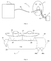
- Fig 1 shows a gas delivery equipment comprising a cannula assembly 2 according to the prior art that fluidly connects a patient 1 to a high flow generator 3 or "HFG", such as the device called Optiflow TM commercialized by Fisher & Paykel.
- HFG high flow generator
- the cannula assembly 2 comprises an elongated flexible tubing 20, such as a flexible hose, comprising, at one end, a nasal sub-system or nasal gas-delivery system 21 fluidly connected to the nose of patient 1, thereby delivering a respiratory gas to the patient 1.
- the elongated flexible tubing 20 is fluidly connected, at its other end, to the HFG 3.
- the nasal sub-system 21 comprises a hollow body 22 with an inner chamber 22a, acting as a manifold for receiving the respiratory gas conveyed and fed by the flexible tubing 20, and nasal prongs 23, 24, i.e. little nozzles, in fluid communication with the lumen of the inner chamber 22a of the hollow body 22, that are inserted, in use, into the nostrils of the patient 1 for delivering a respiratory gas to the patient 1 in need thereof.
- Each nasal prong 23, 24 comprises a unique inner channel or passage 123, 124 for conveying the gas from the inner chamber 22a of the hollow body 22 to the nostrils 13, 14 of the patient 1.
- the hollow body 22 can have various shapes, for example be of circular or rectangular cross section.
- the gas fed by the tubing 20 travels successively in the chamber 22a of the hollow body 22 and then in each nasal prongs 23, 24, and eventually is distributed into the nostrils 13, 14 of the patient.
- the gaseous flow delivered by the high flow generator 3 enters into the inner chamber 22a of the hollow body 22 and is then directed to the prongs 23, 24 so that upon inhalation, only a part of the gaseous flow is inspired by the patient 1, as the rest is unfortunately vented to the atmosphere, while escaping through the spacing 325 that inevitably exists.
- both gaseous flows coming, on the one hand, from the high flow generator 3 and, on the other hand, exhaled by the patient do circulate in said spacing 325, thereby creating a positive expiratory pressure before being vented to the atmosphere.
- Figure 3 represents a first embodiment of a gas delivery equipment comprising a first embodiment of a cannula assembly 112 according to the present invention for fluidly connecting a patient 1 to a HFG 3.
- the cannula assembly 112 comprises an elongated flexible tubing 20 connected, on the one hand, to the high flow generator 3, and, on the other hand, to a nasal sub-system or nasal gas-delivery system121 inserted into the nose of patient 1, thereby delivering respiratory gas to the patient 1.
- the nasal gas-delivery system 121 further comprises measurement elements or means for measuring and transmitting physiological signals, such as gas pressure and/or flowrate, to a processing unit 4.
- additional measurement elements or means comprise three measurement lines, namely flexible tubings 42, 43 that are fluidly connected to the nasal gas-delivery system 121 as shown in Figure 3 .
- Figure 4 shows an embodiment of a nasal gas-delivery system 21 according to the present invention. It comprises a hollow body 22 having any suitable shape, for example a circular or rectangular section, and providing an inlet 22b receiving a respiratory gas fed by the flexible tubing 20, whereas the outlet orifice 44c, part of a sensing module 44, recovers the expiratory gas of the patient.
- a hollow body 22 having any suitable shape, for example a circular or rectangular section, and providing an inlet 22b receiving a respiratory gas fed by the flexible tubing 20, whereas the outlet orifice 44c, part of a sensing module 44, recovers the expiratory gas of the patient.
- the nasal gas-delivery system 21 further comprises two nasal prongs 23, 24 which deliver the gas to the patient, that comprises two deformable flanges 25, 26 separated by a common wall 27 for performing a gas tight seal with the patient's nose and for thus better recovering the gas expired by the patient.
- the sensing module 44 comprises two ports 44a, 44b which will give access to the flow measurement, as explained in connection with Figure 5 .
- Fig. 5 is a cross sectional view of an embodiment of a sensing module 44.
- the sensing module 44 comprises, in the present embodiment, a circular, hollow body 45 comprising an internal chamber 44d and an inner wall 44f arranged in that internal chamber 44d.
- the inner wall 44f restricts locally the diameter of the chamber 44d, i.e. the passage for the gas, thereby forming a restriction of passage 44g and thus creating a pressure drop when a gaseous flow circulates in chamber 44d.
- First and second ports 44a, 44b are provided to fluidly connect the internal chamber 44d upstream and downstream of the restriction formed by inner wall 44f.
- Both first and second ports 44a, 44b, respectively, comprise an exit orifice 244a, 244b, respectively, through which the gas can exit the internal chamber 44d.
- First port 44a is itself fluidly connected to a first flexible tubing 42 for feeding gas to the first flexible tubing 42
- second port 44b is itself fluidly connected to a second flexible tubing 43 for feeding gas to the second flexible tubing 43.
- Figures 4 and 6 show the sensing module 44 fluidly connected to the nasal gas-delivery system 21 of Figure 3 .
- Fig. 6 is a cross sectional view showing the inner design of the nasal gas-delivery system 21 of Figure 3 and the sensing module 44 fluidly connected to said nasal gas-delivery system 21 and locked and maintained therein thanks to the contact between edges 44e, 22c.
- the nasal prongs 23, 24 are inserted into the patient's nostrils 13, 14.
- the inlet 22b of the main hollow body of the nasal gas-delivery system 21, that receives the gas from the flexible tubing 20, is in fluid communication with a first inner chamber 22a that is itself in fluid communication with the inner passages 123, 124 of the prongs 23, 24 so that gas can circulate from the tubing 20 to the prongs 23, 24, via the first inner chamber 22a, and can thereby be delivered to the nostrils 13, 14.
- conduits 125, 126 are in fluid communication with a second inner chamber 22d arranged in the main body of the nasal gas-delivery system 21, that comprises a gas outlet orifice 44c. From the gas outlet orifice 44c, the gases can be easily collected.
- the nasal gas-delivery system 21 comprises two flanges 25, 26 ensuring gas tightness with the outer regions of the nose of the patient.
- nostrils 13, 14 comprise outer walls 13a, 14a, also called “ala” of the nose, and the nasal septum 13b ends by the columella 13c as illustrated in Fig. 6 .
- Flexible flange 25 of the nasal gas-delivery system 21 of the invention which is deformable, comes into contact with the ala 13q (in 25a), whereas the flange 26 comes into contact with the ala 14a (in 26a), and whereas flexible wall 27, which also comprises a deformable portion, comes into contact with the columella 13c (in 27a).
- Those contact areas 25a, 26a, 27a create a gas seal around the nostrils 13, 14, i.e. on the border delimiting the nostril's entrance.
- the gaseous flow, such as air, conveyed by the tubing 20 enters into the internal chamber 22a of the hollow body 22, travels through the first and second conduits 123, 124 of the pair of prongs 23, 24 and is then delivered to the nostrils 13, 14 of the patient.
- the nasal gas-delivery 21 can be made of soft silicon material so as to be light for the patient. Further, it preferably comprises one or several straps, a headgear or similar a fixing system (not shown) for maintaining the nasal gas delivery system 21 in position in the nostrils 13, 14 of the patient.
- processing unit 4 which comprises processing means or devices for processing signal(s), such as one or several microcontrollers.
- the gas travelling into the internal chamber 44d is submitted to a slight pressure drop during its propagation towards the second and third ports 44a, 44b due to the presence of the internal wall 44f, as above explained.
- Such a structure constitutes a flow sensor so that gas pressure measurements can be made through the second and third ports 44a, 44b and then forwarded to the processing unit 4 by the flexible tubings 42, 43, where they can be processed.
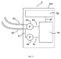
- the processing unit 4 comprises a casing 444 that comprises two pressure sensors 4a, 4b, i.e. a first pressure sensor 4a and a second pressure sensor 4b.
- First sensor 4a is connected to an internal tubing or gas circuit 41 which is fluid communication with tubing 42 and port 44a of sensing module 44.
- the first pressure sensor 4a measures the pressure that exists close to the patient's nostrils 13, 14.
- First pressure sensor 4a is electrically connected, e.g. with cable 4c, to a controller 4e which will further transform and process the pressure information or signal delivered by the first sensor 4a. For instance, the average pressure over a given period of time, such as 1 sec, will help detect a partial occlusion of the passage 44g due to the accumulation of secretions.
- the second pressure sensor 4b is connected to first and second tubing 42, 43 which are respectively connected to the first and second ports 44a, 44b of the sensing module 44.
- the second pressure sensor 4b is preferably a differential pressure sensor allowing measuring the slight pressure difference, i.e. pressure drop, that exists between tubing 42, 43, said pressure drop resulting from the gas pressure decrease caused by the inner wall 44f of the sensing module 44.
- the second sensor 4b is electrically connected, e.g. with cable 4d, to controller 4e which will, here again, further transform and process the pressure information or signal delivered by the second sensor 4b.
- controller 4e is able to determine the absolute value of the flow, relying on a stored lookup table, for translating the differential pressure readings from pressure sensor 4b to actual gas flow values.
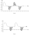
- FIG. 8 illustrates the gaseous flow (in L/min) that is measured by unit 4 over the time (in sec).
- the flow is swinging around a mean value Qb (i.e. an average flow value) representing the flow coming off the HFG 3.
- Qb i.e. an average flow value
- the flow of the patient will sum up with the flow from the HFG 3 and the instantaneous flow traveling in the chamber 44d will rise above the average flow value.
- Fig. 9 is a similar illustration of the gaseous flow (in L/min) that is measured by the unit 4 over the time (in sec). The difference here is that there is a period of time during inspiration phases, where the flow becomes negative. This means that the demand of the patient exceeds the flow delivered by the HFG 3 and that flow comes backward that is sucked from ambient air by the patient 1, traveling from inner chamber 44d to exhaust ports 125, 126 of the nasal prongs. This situation indicates that the flow delivered by the HFG 3 is inferior to inspiratory peak flow of the patient 1, increasing his work of breathing. This should be notified to the physician.
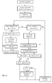
- Fig. 10 is the description of one algorithm that could be implemented in unit 4 and operated by the controller 4e to feed the medical team with useful information.
- a low-pass filter with a cut-off frequency within the range of 0.005 to 0.1 Hz, typically 0.01 Hz is applied. This has the benefit of removing the breathing pattern of the patient 1 whose frequency is usually in the range of 0.1 to 1 Hz and gives access to the baseline flow Qb representing the flow delivered by the HFG 3.
- Such portion of the algorithm is continuously running in order to take into account any setting or adjustment of the flow that has to be delivered by the High Flow Generator 3.
- This value of Qb is then used to define two limits comprising an upper limit and a lower limit, the lower one being slightly lower and the upper one being slightly greater than Qb.
- the lower value is set as the maximum of 90% of Qb or Qb - 3 L/min, whereas the upper limit is set as the minimum of 110% of Qb or Qb + 3L/min.
- the controller 4e verifies the conditions. In case the flow goes below the set lower limit, the volume Vi is accumulated over time, when the flow becomes greater than the low-limit the accumulation is terminated and the tidal volume of the patient 1 is calculated. It is important to note that in the same period of time, a second algorithm checks whether the flow is negative to determine the volume Vi0 the patient would have breath on his/her own due to a demand exceeding the flow Qb delivered by the HFG 3.
- controller 4e can electronically transfer the information by means of an electric cable 4f or other communication device to a visual interface 4g, such as a display.
- the processing unit 4 can further comprise additional signal system, such as an acoustic alarm, for alerting the physician or the user in case where the processing unit 4 detects that one parameter is out of a given range of threshold values.
- additional signal system such as an acoustic alarm
- the nasal cannula By performing a tight seal around the patient's nose, the nasal cannula allows providing meaningful parameters to the physician such as respiratory rate, inspiratory and expiratory volumes or guidance to optimize the setting of the High Flow Generator HFG.
- this configuration could suffer a lack of tolerance from the patient due to the permanent contact of the nasal cannula around his/her nose.
- Another embodiment would be to enhance the comfort of wearing the nasal cannula by limiting the areas of contact with the nose of the patient while keeping the most important parameter available, respiratory rate, along with guidance to optimize the setting of the HFG.
- Figure 11 shows another embodiment of the nasal gas-delivery system 21 according to the present invention. It comprises a hollow body 22 having any suitable shape, for example a circular or rectangular section, and providing an inlet 22b receiving a respiratory gas fed by the flexible tubing 20, whereas the outlet orifice 44c, part of a sensing module 44, recovers the expiratory gas of the patient.
- a hollow body 22 having any suitable shape, for example a circular or rectangular section, and providing an inlet 22b receiving a respiratory gas fed by the flexible tubing 20, whereas the outlet orifice 44c, part of a sensing module 44, recovers the expiratory gas of the patient.
- the nasal gas-delivery system 21 further comprises two nasal prongs 23, 24 for delivering the gas to the patient, which comprise two deformable flanges 25, 26 separated by a common wall 27.
- the flanges 25, 26 are shortened on purpose so as not to come into contact with the patient's nose, as explained below with respect to Fig. 12 .
- sensing module 44 comprises two ports 44a, 44b, giving access to the flow measurement, as explained in connection with Figure 5 .
- Fig. 12 is a cross sectional view showing the inner design of the nasal gas-delivery system 21 of Figure 11 and the sensing module 44 fluidly connected to said nasal gas-delivery system 21 and locked and maintained therein by means of the contact between edges 44e, 22c.
- the nasal prongs 23, 24 are inserted into the patient's nostrils 13, 14.
- the inlet 22b of the main hollow body of the nasal gas-delivery system 21, that receives the gas from the flexible tubing 20, is in fluid communication with a first inner chamber 22a that is itself in fluid communication with the inner passages 123, 124 of the prongs 23, 24 so that gas can circulate from the tubing 20 to the prongs 23, 24, via the first inner chamber 22a, and can thereby be delivered to the nostrils 13, 14.
- conduits 125, 126 are in fluid communication with a second inner chamber 22d arranged in the main body of the nasal gas-delivery system 21, that comprises a gas outlet orifice 44c. From the gas outlet orifice 44c, the gases can be easily collected.
- the nasal gas-delivery system 21 comprises two flanges 25, 26 which are shortened so as to avoid any contact with the nose of the patient, enhancing the comfort of wearing the cannula. This is made possible in providing the contact point 27a of the flexible wall 27 and the columella 13c higher than the upper edges of the flanges 25, 26, respectively 25b, 26b. A difference of few millimeters, typically 1, 2 or 3 mm will be enough to accommodate various noses variations in a given population (adults, infants). As a consequence, vents 25c, 26c are created between the lower ends of the alas 13b, 14b and upper edges of the flanges, 25b, 26c respectively.
- the gaseous flow, such as air, conveyed by the tubing 20 enters into the internal chamber 22a of the hollow body 22, travels through the first and second conduits 123, 124 of the pair of prongs 23, 24 and is then delivered to the nostrils 13, 14 of the patient.
- vents 25c, 26c which are fluidly connected to the vent conduit 22d and subsequently to internal chamber 44d thereby allowing the gas escaping to the atmosphere by venting port(s) 44c.
- the amount of gas escaping through vents 25c, 26c or venting port 44c will depend on the respective resistance to flow of such ports. For example if the surface area around the nose of vents 25c, 26c is greater than the surface area of the conduits 125, 126, a larger portion of the gas will escape from vents 25b, 26c than venting port 44c, and conversely.
- both gaseous flows coming from the internal chamber 22a of the hollow body 22, on the one hand, and exhaled by the patient, on the other hand, will be vented to the atmosphere either through vents 25c, 26c and the conduits 125,126, vent conduits 22d and subsequently to internal chamber 44d, and venting port or gas outlet orifice 44c, thereby creating a positive expiratory pressure or PEP.
- the amount of gas vented through ports 25c, 26c, 44c will also depend of the surface ratio explained above.
- the nasal gas-delivery 21 can be made of soft silicon material so as to be light for the patient. Further, it preferably comprises one or several straps, a headgear or similar a fixing system (not shown) for maintaining the nasal gas delivery system 21 in position in the nostrils 13, 14 of the patient.
- Fig. 13 illustrates the gaseous flow (in L/min) that is measured by unit 4 over the time (in sec).
- the flow is swinging around a mean value Qf (i.e. an average flow value) representing a portion of the flow coming of the HFG 3 by virtue of the spacing 25a, 26a.
- Qf i.e. an average flow value
- the flow of the patient will sum up with the flow of the HFG 3 and the instantaneous flow traveling in the chamber 44d will rise above the average flow value.
- the last 2 inspirations are greater than the previous ones, indicating for example that the patient has increased his respiratory demand, resulting in a portion where the flow becomes negative.
- Fig. 14 exhibits an algorithm that could be implemented in unit 4 and operated by the controller 4e to feed the medical team with useful information.
- a low-pass filter with a cut-off frequency within the range of 0.005 to 0.1 Hz, typically 0.01 Hz is applied. This has the benefit of removing the breathing pattern of the patient 1, whose frequency is usually in the range of 0.1 to 1 Hz, and gives access to the average flow Qf that is measured by the unit 4, which, by virtue of the spacing 25a and 26a is inferior to the baseline flow Qb representing the flow delivered by the HFG 3.
- Such portion of the algorithm is continuously running in order to take into account any setting or adjustment of the flow that has to be delivered by the High Flow Generator 3.
- This value of Qf is then used to define two limits comprising a upper limit and a lower limit, the lower one being slightly lower and the upper one being slightly greater than Qf.
- the lower value is set as the maximum of 90% of Qf or Qf - 1 L/min, whereas the upper limit is set as the minimum of 110% of Qf or Qf + 1 L/min.
- the controller 4e verifies the conditions. In case the flow goes below the set lower limit, the condition of an inspiration is detected. It is important to note that in the same period of time, a second algorithm checks whether the flow is negative to determine that the patient had to breath on his/her own due to a demand exceeding the flow Qb delivered by the HFG 3.
- a specific algorithm will check whether the flow was negative during the previous inspiration, which could expose the patient to respiratory fatigue.
- a signal will be sent to the medical team, asking them to check the flow delivered by the HFG 3 and increase its value, if necessary.
- the nasal cannula e.g. ensuring tightness or not around of the patient's nose
- several information are made available to the physician, such as, at least the respiratory rate of the patient and an inadequacy of his/her needs relating to the set flow of the High Flow Generator 3.
- Another interesting parameter would be the intra-nasal pressure of the patient. As this parameter results on the flow set by the physician, the geometry of the patient's nose and type of nasal cannula, it is a widely variable parameter, yet essential:
- Fig. 15 represents an optimization of Fig. 3 , where the High Flow Generator 3 is embedded into the processing unit 4.
- Processing unit 4 therefore encompasses both the ability to deliver a flow to the patient via the tubing 20 as described earlier and to display information to the user such as respiratory rate, inspiratory and expiratory volumes etc...
- Fig.16 provides the same details as in Fig.7 but also includes the flow generator 33 (not described here), which delivers the flow to the patient.
- An additional pressure sensor 3a measures the pressure at the inlet of the tubing 21. Such measure is made possible by an electrical connection by the cable 3c to the controller 4e.
- the tubing 20 and prongs 23, 24 as described in Fig. 6 fluidly connect the pressure sensor 3a to the nasal cavity 13, 14 of the patient. It is understood that these conduits also generate a pressure drop upon transfer of a flow from the generator 33. As the nasal cannula is known, it is possible to get the relationship between the flow that is set by the physician and respective pressure drop operated by the conduits 20, 23, 24. The controller 4e can take into account this pressure drop so as to give access to an estimate of the pressure residing in the nasal cavities 13, 14, e.g. the intra-nasal pressure.
- the processing unit 4 can further comprise additional signal system, such as an acoustic alarm, for alerting the physician or the user in case where the processing unit 4 detects that the intra-nasal pressure is out of a given range of threshold values
Landscapes
- Health & Medical Sciences (AREA)
- Life Sciences & Earth Sciences (AREA)
- Pulmonology (AREA)
- General Health & Medical Sciences (AREA)
- Veterinary Medicine (AREA)
- Biomedical Technology (AREA)
- Heart & Thoracic Surgery (AREA)
- Public Health (AREA)
- Engineering & Computer Science (AREA)
- Animal Behavior & Ethology (AREA)
- Emergency Medicine (AREA)
- Hematology (AREA)
- Anesthesiology (AREA)
- Biophysics (AREA)
- Physiology (AREA)
- Physics & Mathematics (AREA)
- Otolaryngology (AREA)
- Pathology (AREA)
- Medical Informatics (AREA)
- Molecular Biology (AREA)
- Surgery (AREA)
- Measurement Of The Respiration, Hearing Ability, Form, And Blood Characteristics Of Living Organisms (AREA)
- Respiratory Apparatuses And Protective Means (AREA)
Abstract
Description
- The invention concerns a gas delivery installation or assembly comprising a nasal sub-system or nasal gas-delivery system comprising two prongs that are inserted into the patient's nostrils for delivering a respiratory gas to a patient in need thereof, and a sensing module, and preferably a processing unit and a high flow generator (HFG) for delivering a respiratory gas to a patient.
- Nasal High Flow Therapy or NHFT is a widespread therapy used in many hospitals, especially in acute care services, for treating respiratory distresses. It does not require any mechanical ventilation and can prevent patients from being intubated.
- Basically, NHFT consists in providing a humidified, high flow of a respiratory gas to a patient in need thereof. Gaseous flows typically range from 10 to 60 L/min in adults and 1 to 10 L/min in infants.
- The gas is delivered by a nasal cannula system that typically comprises two prongs that are inserted into the patient's nostrils, while not totally occluding them. The prongs deliver the gaseous flow that the patient inhales and the space that exists between the outer portion of the prongs and the inner wall of the nostrils helps the expired gaseous flow to be vented upon exhalation.
- NHFT provides many advantages compared to continuous oxygen treatments or even to non-invasive ventilation, e.g.:
- the gaseous flow can be enriched with Oxygen (O2) up to 100%, i.e. the respiratory gas can be composed of air, O2-enriched air (>22 vol% of O2) or pure O2;
- the set flow can be greater than the inspiratory peak flow of the patient so as to limit his/her work while breathing, thereby assisting preventing fatigue of respiratory muscles;
- the flow helps flushing out CO2 from the dead space of the upper airways, thereby enhancing the ventilation; and
- the flow and the space between the prongs and the nostrils create a positive pressure, which exhibits a beneficial action on ventilation;
- Furthermore, this therapy has many advantages such as:
- only a gas flow and a level of oxygen have to be set by the physician or other medical service provider;
- the nasal cannula is easy to be put in place; and
- the patient can speak and even eat, while receiving the therapy.
- However, so far, physicians or similar do not have easily access to parameters that might help them for setting the right gas flow and gas concentration(s) for thereby obtaining the best therapy for a given patient, as they usually rely only on oxygen saturation, i.e. SpO2.
- Indeed, in some cases, a physician may decide to increase the O2 concentration for reaching an adequate O2-saturation in the blood of the patient, whereas increasing the overall flow of gas would have been a better solution if the patient inspiratory flow was greater than the set one.
- Furthermore, despite NHFT, it has been noticed that some patients under NHFT persist in their respiratory distress and have to be intubated eventually. One indicator of a possible future intubation is a persistent dyspnea despite the NHFT therapy or a modification of the minute volume ventilation. However, such an indicator is not easily available to physicians or similar.
- Having access to these useful parameters, such as minute ventilation and the respiratory rate, would be valuable for physicians or similar as they could be used for better controlling NHFT in better setting or adjusting the parameters of the treatment or anticipating failure of the therapy and initiating in a timely manner another therapy, such as Non Invasive Ventilation.
- It is one purpose of the present invention to improve NHFT in providing additional parameters to physicians or similar, for helping them to better assess the patient condition and better adjust the "settings" of the treatment thereby improving the efficiency of the treatment of the patient so as to avoid or limit the intubation rate, and/or to reduce the length of stay of the patient in hospital, in case of intubation.
- Another goal of the present invention is to provide a nasal high flow therapy (NHFT) assembly for providing an efficient NHFT to patients.
- One solution according to the present invention concerns a nasal high flow therapy (NHFT) assembly suitable for providing a NHFT to patients, comprising:
- A) a nasal gas-delivery system to be connected to a nose of a patient for delivering a respiratory gas to the patient, comprising:
- a hollow body with an inner chamber comprising an inlet for receiving a respiratory gas, and
- a pair of nasal prongs in fluid communication with the inner chamber of the hollow body, each nasal prong comprising a first inner passage fluidly connecting the internal chamber of the hollow body with a nostril of the patient, and
- the hollow body comprises a pair of second passages for fluidly connecting a nostril with a vent conduit arranged in the hollow body, said vent conduit comprising one venting port, and
- B) a sensing module comprising a hollow body comprising an internal chamber with an inlet orifice, an outlet orifice, a first port, a second port and an inner wall arranged between the first and second ports and radially projecting into the internal chamber thereby forming a restriction of passage for the gas in said internal chamber, said first and second ports each comprising an exit orifice, the inlet orifice of the sensing module being fluidly connected to the venting port of the vent conduit of the nasal gas-delivery system.
- Depending on the embodiment the nasal high flow therapy (NHFT) assembly of the present invention can comprise one or more of the following features:
- a pair of flexible flanges are arranged around the nasal prongs of the nasal gas-delivery system thereby ensuring gas-tightness when the nasal prongs are inserted into the patient's nostrils.
- the nasal prongs have a tronconical shape.
- flexible flanges are made of silicon or any other suitable flexible material.
- the inner wall radially projecting into the internal chamber of the nasal gas-delivery system has a disk-shape with a central orifice.
- the pair of flexible flanges of the nasal gas-delivery system comprises a common flexible wall.
- the nasal gas-delivery system further comprises a fixing system for maintaining the nasal prongs in position into the patient's nostrils.
- the assembly further comprises a processing unit comprising a first pressure sensor and a second pressure sensor, electrically connected to a controller; a controller for processing information provided by the first and second
- pressure sensors; the first pressure sensor and a second pressure sensor being connected to the internal gas circuit, said internal gas circuit being in fluid communication with the first port of the sensing module.
- the internal gas circuit of the processing unit is in fluid communication with the first port of the sensing module by a first tubing.
- the second pressure sensor of the processing unit is a differential pressure sensor.
- the second pressure sensor of the processing unit is connected to the first and second ports of the sensing module by the first tubing and a second tubing, i.e. hoses, gas conducts or similar.
- the controller is electrically connected to a visual interface for displaying information, such as a display screen.
- the assembly further comprises a high flow generator (HFG) for delivering a high flow of gas, said HFG being in fluid communication with the inlet of the inner chamber of the hollow body of the nasal gas-delivery system.
- the HFG is fluidly connected to the inlet of the inner chamber of the hollow body of the nasal gas-delivery system by a flexible tubing, such as hoses or gas conducts.
- the sensing module is a Pitot-type sensor or any other suitable sensor.
- Further, the present invention also concerns a method of analyzing breathing activity of a patient whose nose is connected to a nasal gas-delivery system as described hereabove, i.e. a nasal gas-delivery system according to the present invention, the method comprising the steps of:
- a) measuring a baseline respiratory flow Qb flowing through the sensing module,
- b) defining an upper value of 1.1*Qb,
- c) defining a lower limit of 0.9*Qb,
- d) during patient breathing through the nasal gas-delivery system, measuring a breathing associated flow through the sensing module,
- e) determining if the breathing associated flow through the sensing module is below the lower limit and/or above the upper limit,
- f) when the breathing associated flow through the sensing module is below the lower limit, determining the net volume of flow attributable to gas drawn off by the patient Vi0 wherein a preset threshold for Vi0 is defined as indicative of an excessive patient breathing effort,
- g) when the breathing associated flow through the sensing module is above the upper limit, determining if the net volume of exhaled flow Ve attributable to excess flow from the nasal gas-delivery system exceeds a predetermined amount or a predetermined amount for a predetermined number of times within a predefined period.
- Other features, aspects and advantages of the present invention will become apparent from the following detailed description when taken in conjunction with the accompanying drawings which illustrates, by way of examples, the present invention, among which:
-
Fig. 1 is a schematic representation of a gas delivery assembly comprising a nasal interface according to the prior art, -
Fig. 2 is a schematic representation of the nasal interface ofFig. 1 , -
Fig. 3 represents a gas delivery assembly comprising a nasal interface and a sensing module, -
Fig. 4 represents an embodiment of the nasal interface and the sensing module according to the present invention, -
Fig. 5 represents a cross section of the sensing module according to the present invention, -
Fig. 6 represents a cross section of the nasal interface and the sensing module according to the present invention, -
Fig. 7 represents an embodiment of a processing unit of the gas delivery assembly ofFig. 3 , -
Fig. 8 represents an acquisition of the breathing pattern of a patient with the sensing module and processing unit, -
Fig. 9 represents another acquisition of the breathing pattern of a patient with the sensing module and processing unit, and -
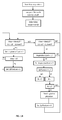
Fig. 10 is an algorithm running in the processing unit, -
Fig. 11 represents another embodiment of the nasal interface and the sensing module according to the present invention, -
Fig. 12 represents a cross section ofFig.11 , -
Fig. 13 represents another acquisition of the breathing pattern of the patient with the sensing module and processing unit, -
Fig. 14 is another algorithm running in the processing unit, -
Fig. 15 is another embodiment of the gas delivery assembly comprising a nasal interface and a sensing module, and -
Fig. 16 is another embodiment of the processing unit of the gas delivery assembly ofFig.15 . -
Fig 1 shows a gas delivery equipment comprising acannula assembly 2 according to the prior art that fluidly connects apatient 1 to ahigh flow generator 3 or "HFG", such as the device called Optiflow™ commercialized by Fisher & Paykel. - The
cannula assembly 2 comprises an elongatedflexible tubing 20, such as a flexible hose, comprising, at one end, a nasal sub-system or nasal gas-delivery system 21 fluidly connected to the nose ofpatient 1, thereby delivering a respiratory gas to thepatient 1. The elongatedflexible tubing 20 is fluidly connected, at its other end, to theHFG 3. - As detailed in
Fig. 2 , thenasal sub-system 21 comprises ahollow body 22 with aninner chamber 22a, acting as a manifold for receiving the respiratory gas conveyed and fed by theflexible tubing 20, andnasal prongs inner chamber 22a of thehollow body 22, that are inserted, in use, into the nostrils of thepatient 1 for delivering a respiratory gas to thepatient 1 in need thereof. Eachnasal prong passage inner chamber 22a of thehollow body 22 to thenostrils patient 1. - The
hollow body 22 can have various shapes, for example be of circular or rectangular cross section. The gas fed by thetubing 20 travels successively in thechamber 22a of thehollow body 22 and then in each nasal prongs 23, 24, and eventually is distributed into thenostrils - With such a prior art equipment, a gas tight connection/insertion of the
prongs nostrils nasal prongs inner walls 13q, 14a of thenostrils spacing 325 always exists between theinner walls 13q, 14a of thenostrils nasal prongs - The gaseous flow delivered by the
high flow generator 3 enters into theinner chamber 22a of thehollow body 22 and is then directed to theprongs patient 1, as the rest is unfortunately vented to the atmosphere, while escaping through the spacing 325 that inevitably exists. - Upon expiration, both gaseous flows coming, on the one hand, from the
high flow generator 3 and, on the other hand, exhaled by the patient do circulate in saidspacing 325, thereby creating a positive expiratory pressure before being vented to the atmosphere. - Such an architecture is not ideal because such gas loss cannot be quantified and therefore prevent the access to precious respiratory data such as volumes.
-
Figure 3 represents a first embodiment of a gas delivery equipment comprising a first embodiment of acannula assembly 112 according to the present invention for fluidly connecting apatient 1 to aHFG 3. As inFigures 1 and 2 , thecannula assembly 112 comprises an elongatedflexible tubing 20 connected, on the one hand, to thehigh flow generator 3, and, on the other hand, to a nasal sub-system or nasal gas-delivery system121 inserted into the nose ofpatient 1, thereby delivering respiratory gas to thepatient 1. - According to the present invention, the nasal gas-
delivery system 121 further comprises measurement elements or means for measuring and transmitting physiological signals, such as gas pressure and/or flowrate, to aprocessing unit 4. These additional measurement elements or means comprise three measurement lines, namelyflexible tubings delivery system 121 as shown inFigure 3 . -
Figure 4 , shows an embodiment of a nasal gas-delivery system 21 according to the present invention. It comprises ahollow body 22 having any suitable shape, for example a circular or rectangular section, and providing aninlet 22b receiving a respiratory gas fed by theflexible tubing 20, whereas theoutlet orifice 44c, part of asensing module 44, recovers the expiratory gas of the patient. - The nasal gas-
delivery system 21 further comprises twonasal prongs deformable flanges common wall 27 for performing a gas tight seal with the patient's nose and for thus better recovering the gas expired by the patient. - Further, the
sensing module 44 comprises twoports Figure 5 . -
Fig. 5 is a cross sectional view of an embodiment of asensing module 44. Thesensing module 44 comprises, in the present embodiment, a circular,hollow body 45 comprising aninternal chamber 44d and aninner wall 44f arranged in thatinternal chamber 44d. Theinner wall 44f restricts locally the diameter of thechamber 44d, i.e. the passage for the gas, thereby forming a restriction ofpassage 44g and thus creating a pressure drop when a gaseous flow circulates inchamber 44d. First andsecond ports internal chamber 44d upstream and downstream of the restriction formed byinner wall 44f. Both first andsecond ports exit orifice internal chamber 44d.First port 44a is itself fluidly connected to a firstflexible tubing 42 for feeding gas to the firstflexible tubing 42, whereassecond port 44b is itself fluidly connected to a secondflexible tubing 43 for feeding gas to the secondflexible tubing 43. -
Figures 4 and6 show thesensing module 44 fluidly connected to the nasal gas-delivery system 21 ofFigure 3 . -
Fig. 6 is a cross sectional view showing the inner design of the nasal gas-delivery system 21 ofFigure 3 and thesensing module 44 fluidly connected to said nasal gas-delivery system 21 and locked and maintained therein thanks to the contact betweenedges - The nasal prongs 23, 24 are inserted into the patient's
nostrils inlet 22b of the main hollow body of the nasal gas-delivery system 21, that receives the gas from theflexible tubing 20, is in fluid communication with a firstinner chamber 22a that is itself in fluid communication with theinner passages prongs tubing 20 to theprongs inner chamber 22a, and can thereby be delivered to thenostrils conduits inner chamber 22d arranged in the main body of the nasal gas-delivery system 21, that comprises agas outlet orifice 44c. From thegas outlet orifice 44c, the gases can be easily collected. - Further, the nasal gas-
delivery system 21 comprises twoflanges nostrils outer walls nasal septum 13b ends by thecolumella 13c as illustrated inFig. 6 .Flexible flange 25 of the nasal gas-delivery system 21 of the invention, which is deformable, comes into contact with the ala 13q (in 25a), whereas theflange 26 comes into contact with the ala 14a (in 26a), and whereasflexible wall 27, which also comprises a deformable portion, comes into contact with thecolumella 13c (in 27a). Thosecontact areas nostrils - With such a configuration, the gaseous flow, such as air, conveyed by the
tubing 20 enters into theinternal chamber 22a of thehollow body 22, travels through the first andsecond conduits prongs nostrils - During the inhalation phases of the patient, a part of the gaseous flow is inspired by the patient, whereas the rest of the gaseous flow is directed to the
conduits vent conduit 22d and subsequently tointernal chamber 44d thereby allowing this excess of gas escaping to the atmosphere by venting port(s) 44c. - In contrast, during the exhalation phases of the patient, both gaseous flows coming from the
internal chamber 22a of thehollow body 22, on the one hand, and exhaled by the patient, on the other hand, pass through theconduits conduits 22d and subsequently tointernal chamber 44d, and venting port orgas outlet orifice 44c, thereby creating a positive expiratory pressure or PEP. - The nasal gas-
delivery 21 can be made of soft silicon material so as to be light for the patient. Further, it preferably comprises one or several straps, a headgear or similar a fixing system (not shown) for maintaining the nasalgas delivery system 21 in position in thenostrils - In
Fig. 7 , theflexible tubing processing unit 4, which comprises processing means or devices for processing signal(s), such as one or several microcontrollers. - As illustrated in
Fig. 5 , the gas travelling into theinternal chamber 44d is submitted to a slight pressure drop during its propagation towards the second andthird ports internal wall 44f, as above explained. Such a structure constitutes a flow sensor so that gas pressure measurements can be made through the second andthird ports processing unit 4 by theflexible tubings - The
processing unit 4 comprises acasing 444 that comprises twopressure sensors first pressure sensor 4a and asecond pressure sensor 4b.First sensor 4a is connected to an internal tubing orgas circuit 41 which is fluid communication withtubing 42 andport 44a ofsensing module 44. Thefirst pressure sensor 4a measures the pressure that exists close to the patient'snostrils First pressure sensor 4a is electrically connected, e.g. withcable 4c, to acontroller 4e which will further transform and process the pressure information or signal delivered by thefirst sensor 4a. For instance, the average pressure over a given period of time, such as 1 sec, will help detect a partial occlusion of thepassage 44g due to the accumulation of secretions. - Similarly, the
second pressure sensor 4b is connected to first andsecond tubing second ports sensing module 44. - The
second pressure sensor 4b is preferably a differential pressure sensor allowing measuring the slight pressure difference, i.e. pressure drop, that exists betweentubing inner wall 44f of thesensing module 44. Thesecond sensor 4b is electrically connected, e.g. withcable 4d, tocontroller 4e which will, here again, further transform and process the pressure information or signal delivered by thesecond sensor 4b. For instance, based on the geometry of theinner chamber 44d andwall 44f,controller 4e is able to determine the absolute value of the flow, relying on a stored lookup table, for translating the differential pressure readings frompressure sensor 4b to actual gas flow values.Fig. 8 illustrates the gaseous flow (in L/min) that is measured byunit 4 over the time (in sec). As one can see, the flow is swinging around a mean value Qb (i.e. an average flow value) representing the flow coming off theHFG 3. Upon inhalation, most of the flow coming from theHFG 3 will be inspired by thepatient 1 and the instantaneous flow traveling in thechamber 44d will fall below the average flow value. On the opposite, during expiration, the flow of the patient will sum up with the flow from theHFG 3 and the instantaneous flow traveling in thechamber 44d will rise above the average flow value. -
Fig. 9 is a similar illustration of the gaseous flow (in L/min) that is measured by theunit 4 over the time (in sec). The difference here is that there is a period of time during inspiration phases, where the flow becomes negative. This means that the demand of the patient exceeds the flow delivered by theHFG 3 and that flow comes backward that is sucked from ambient air by thepatient 1, traveling frominner chamber 44d to exhaustports HFG 3 is inferior to inspiratory peak flow of thepatient 1, increasing his work of breathing. This should be notified to the physician. - Similarly, being able to calculate the mean value of the flow coming from the
HFG 3 and the amplitude of the flow swings above and under this limit would give access to the inspired volume Vi that is inhaled and to the expired volume Ve that is exhaled by thepatient 1 as well as to the respiratory rate of thepatient 1. -
Fig. 10 is the description of one algorithm that could be implemented inunit 4 and operated by thecontroller 4e to feed the medical team with useful information. - As the flow therapy is started, a low-pass filter with a cut-off frequency within the range of 0.005 to 0.1 Hz, typically 0.01 Hz is applied. This has the benefit of removing the breathing pattern of the
patient 1 whose frequency is usually in the range of 0.1 to 1 Hz and gives access to the baseline flow Qb representing the flow delivered by theHFG 3. - Such portion of the algorithm is continuously running in order to take into account any setting or adjustment of the flow that has to be delivered by the
High Flow Generator 3. - This value of Qb is then used to define two limits comprising an upper limit and a lower limit, the lower one being slightly lower and the upper one being slightly greater than Qb.
- These upper and lower limits will determine whether the patient is inhaling (i.e. lower values) or exhaling (i.e. upper values). The lower value is set as the maximum of 90% of Qb or Qb - 3 L/min, whereas the upper limit is set as the minimum of 110% of Qb or Qb + 3L/min.
- For example, if Qb is determined as 40 L/min, the lower limit is 37 L/min and the upper limit is 43 L/min.
- At any moment, once Qb has been determined, the
controller 4e verifies the conditions. In case the flow goes below the set lower limit, the volume Vi is accumulated over time, when the flow becomes greater than the low-limit the accumulation is terminated and the tidal volume of thepatient 1 is calculated. It is important to note that in the same period of time, a second algorithm checks whether the flow is negative to determine the volume Vi0 the patient would have breath on his/her own due to a demand exceeding the flow Qb delivered by theHFG 3. - When the flow is between the lower and upper limits, there is no specific action performed in terms of volume calculation. However, as soon as the patient starts exhaling, the flow quickly exceeds the upper limit and the volume Ve is accumulated over time.
- In the meantime a specific algorithm will check the values Vi0 and Vi calculated during the previous inspiration.
- If more than 10% of the volume Vi0 was drawn by the patient, this exposes him/her to subsequent respiratory fatigue. In case of 3 occurrences in a row, i.e. 3 consecutives inspiration, a signal will be sent to the medical team, asking them to check the flow delivered by the
HFG 3 and increase its value, if necessary. - In order to send such signal and display all the parameters (pressure, respiratory rate, inspiratory volumes and minute volume ...),
controller 4e can electronically transfer the information by means of anelectric cable 4f or other communication device to a visual interface 4g, such as a display. - The
processing unit 4 can further comprise additional signal system, such as an acoustic alarm, for alerting the physician or the user in case where theprocessing unit 4 detects that one parameter is out of a given range of threshold values. - By performing a tight seal around the patient's nose, the nasal cannula allows providing meaningful parameters to the physician such as respiratory rate, inspiratory and expiratory volumes or guidance to optimize the setting of the High Flow Generator HFG. However, this configuration could suffer a lack of tolerance from the patient due to the permanent contact of the nasal cannula around his/her nose. Another embodiment would be to enhance the comfort of wearing the nasal cannula by limiting the areas of contact with the nose of the patient while keeping the most important parameter available, respiratory rate, along with guidance to optimize the setting of the HFG.
- This alternative would allow the medical team chosing the type of cannula best suiting to their needs while optimizing the patient's comfort.
-
Figure 11 shows another embodiment of the nasal gas-delivery system 21 according to the present invention. It comprises ahollow body 22 having any suitable shape, for example a circular or rectangular section, and providing aninlet 22b receiving a respiratory gas fed by theflexible tubing 20, whereas theoutlet orifice 44c, part of asensing module 44, recovers the expiratory gas of the patient. - The nasal gas-
delivery system 21 further comprises twonasal prongs deformable flanges common wall 27. Theflanges Fig. 12 . - Further,
sensing module 44 comprises twoports Figure 5 . -
Fig. 12 is a cross sectional view showing the inner design of the nasal gas-delivery system 21 ofFigure 11 and thesensing module 44 fluidly connected to said nasal gas-delivery system 21 and locked and maintained therein by means of the contact betweenedges - The nasal prongs 23, 24 are inserted into the patient's
nostrils inlet 22b of the main hollow body of the nasal gas-delivery system 21, that receives the gas from theflexible tubing 20, is in fluid communication with a firstinner chamber 22a that is itself in fluid communication with theinner passages prongs tubing 20 to theprongs inner chamber 22a, and can thereby be delivered to thenostrils conduits inner chamber 22d arranged in the main body of the nasal gas-delivery system 21, that comprises agas outlet orifice 44c. From thegas outlet orifice 44c, the gases can be easily collected. - Further, the nasal gas-
delivery system 21 comprises twoflanges contact point 27a of theflexible wall 27 and thecolumella 13c higher than the upper edges of theflanges - With such a configuration, the gaseous flow, such as air, conveyed by the
tubing 20 enters into theinternal chamber 22a of thehollow body 22, travels through the first andsecond conduits prongs nostrils - During the inhalation phases of the patient, a part of the gaseous flow is inspired by the patient, whereas the rest of the gaseous flow is directed either to ambient through the
vents conduits vent conduit 22d and subsequently tointernal chamber 44d thereby allowing the gas escaping to the atmosphere by venting port(s) 44c. The amount of gas escaping throughvents port 44c will depend on the respective resistance to flow of such ports. For example if the surface area around the nose ofvents conduits vents port 44c, and conversely. - During the exhalation phases of the patient, both gaseous flows coming from the
internal chamber 22a of thehollow body 22, on the one hand, and exhaled by the patient, on the other hand, will be vented to the atmosphere either throughvents vent conduits 22d and subsequently tointernal chamber 44d, and venting port orgas outlet orifice 44c, thereby creating a positive expiratory pressure or PEP. The amount of gas vented throughports - The nasal gas-
delivery 21 can be made of soft silicon material so as to be light for the patient. Further, it preferably comprises one or several straps, a headgear or similar a fixing system (not shown) for maintaining the nasalgas delivery system 21 in position in thenostrils -
Fig. 13 illustrates the gaseous flow (in L/min) that is measured byunit 4 over the time (in sec). As one can see, the flow is swinging around a mean value Qf (i.e. an average flow value) representing a portion of the flow coming of theHFG 3 by virtue of thespacing HFG 3 will be inspired by thepatient 1 and the instantaneous flow traveling in thechamber 44d will fall below the average flow value. On the opposite, during expiration, the flow of the patient will sum up with the flow of theHFG 3 and the instantaneous flow traveling in thechamber 44d will rise above the average flow value. - As one can see, the last 2 inspirations are greater than the previous ones, indicating for example that the patient has increased his respiratory demand, resulting in a portion where the flow becomes negative. This means that the demand of the patient exceeds the flow delivered by the
HFG 3 and that the flow comes backward, that is sucked from ambient air by thepatient 1, traveling frominner chamber 44d to exhaust ports 125,126 of the nasal prongs. -
Fig. 14 exhibits an algorithm that could be implemented inunit 4 and operated by thecontroller 4e to feed the medical team with useful information. - As the flow therapy is started, a low-pass filter with a cut-off frequency within the range of 0.005 to 0.1 Hz, typically 0.01 Hz is applied. This has the benefit of removing the breathing pattern of the
patient 1, whose frequency is usually in the range of 0.1 to 1 Hz, and gives access to the average flow Qf that is measured by theunit 4, which, by virtue of thespacing HFG 3. - Such portion of the algorithm is continuously running in order to take into account any setting or adjustment of the flow that has to be delivered by the
High Flow Generator 3. - This value of Qf is then used to define two limits comprising a upper limit and a lower limit, the lower one being slightly lower and the upper one being slightly greater than Qf.
- These upper and lower limits will determine whether the patient is inhaling (i.e. lower values) or exhaling (i.e. upper values). The lower value is set as the maximum of 90% of Qf or Qf - 1 L/min, whereas the upper limit is set as the minimum of 110% of Qf or Qf + 1 L/min.
- For example, if Qf is determined as 5 L/min, the lower limit is 4.5 L/min and the upper limit is 5.5 L/min.
- At any moment, once Qf has been determined, the
controller 4e verifies the conditions. In case the flow goes below the set lower limit, the condition of an inspiration is detected. It is important to note that in the same period of time, a second algorithm checks whether the flow is negative to determine that the patient had to breath on his/her own due to a demand exceeding the flow Qb delivered by theHFG 3. - When the flow is between the lower and upper limits a specific algorithm will check whether the flow was negative during the previous inspiration, which could expose the patient to respiratory fatigue. In case of 3 occurrences in a row, i.e. 3 consecutives inspiration, a signal will be sent to the medical team, asking them to check the flow delivered by the
HFG 3 and increase its value, if necessary. - By counting the number of time an inspiration was detected over a given period, it is easy to determine the respiratory rate of the patient.
- Depending on the selection of the nasal cannula, e.g. ensuring tightness or not around of the patient's nose, several information are made available to the physician, such as, at least the respiratory rate of the patient and an inadequacy of his/her needs relating to the set flow of the
High Flow Generator 3. Another interesting parameter would be the intra-nasal pressure of the patient. As this parameter results on the flow set by the physician, the geometry of the patient's nose and type of nasal cannula, it is a widely variable parameter, yet essential: - It represents the PEEP which the patient is exposed to so the physician may want to adjust the flow so as to reach a pressure enhancing the gas exchanges
- It can be harmful if its value is too high, promoting lung distension
- The way to make available this useful parameter is described hereafter:
-
Fig. 15 represents an optimization ofFig. 3 , where theHigh Flow Generator 3 is embedded into theprocessing unit 4.Processing unit 4 therefore encompasses both the ability to deliver a flow to the patient via thetubing 20 as described earlier and to display information to the user such as respiratory rate, inspiratory and expiratory volumes etc... -
Fig.16 provides the same details as inFig.7 but also includes the flow generator 33 (not described here), which delivers the flow to the patient. An additional pressure sensor 3a measures the pressure at the inlet of thetubing 21. Such measure is made possible by an electrical connection by thecable 3c to thecontroller 4e. - As a matter of fact, the
tubing 20 andprongs Fig. 6 for instance fluidly connect the pressure sensor 3a to thenasal cavity generator 33. As the nasal cannula is known, it is possible to get the relationship between the flow that is set by the physician and respective pressure drop operated by theconduits controller 4e can take into account this pressure drop so as to give access to an estimate of the pressure residing in thenasal cavities processing unit 4e by the mean of thecable 3c) and a predefined look-up table, stored within thecontroller 4e, and associating the pressure drop generated by theconduits - This reconstitution of the intra-nasal pressure can then be transmitted to the visual interface 4g so as to be available to the physician. Here also the
processing unit 4 can further comprise additional signal system, such as an acoustic alarm, for alerting the physician or the user in case where theprocessing unit 4 detects that the intra-nasal pressure is out of a given range of threshold values
Claims (14)
- Nasal high flow therapy assembly comprising:A) a nasal gas-delivery system (21) to be connected to a nose of a patient for delivering a respiratory gas to the patient, comprising:- a hollow body (22) with an inner chamber (22a) comprising an inlet (22b) for receiving a respiratory gas, and- a pair of nasal prongs (23, 24) in fluid communication with the inner chamber (22a) of the hollow body (22), each nasal prong (23, 24) comprising a first inner passage (123; 124) fluidly connecting the internal chamber (22a) of the hollow body (22) with a nostril (13, 14) of the patient, and- the hollow body (22) comprises a pair of second passages (125; 126) for fluidly connecting a nostril (13, 14) with a vent conduit (22d) arranged in the hollow body (22), said vent conduit (22d) comprising one venting port (25a), andB) a sensing module (44) comprising a hollow body (45) comprising an internal chamber (44d) with an inlet orifice (45a), an outlet orifice (44c), a first port and (44a), a second port (44b) and an inner wall (44f) arranged between the first and second ports (44a, 44b) and radially projecting into the internal chamber (44d) thereby forming a restriction of passage for the gas in said internal chamber (44d), said first and second ports (44a, 44b) each comprising an exit orifice (244a, 244b), the inlet orifice (45a) of the sensing module (44) being fluidly connected to the venting port (25a) of the vent conduit (22d) of the nasal gas-delivery system (21).
- The assembly according to Claim 1, wherein a pair of flexible flanges (25, 26) are arranged around the nasal prongs (23, 24) of the nasal gas-delivery system (21).
- The assembly according to Claim 1, wherein the inner wall (44f) radially projecting into the internal chamber (44d) of the nasal gas-delivery system (21) has a disk-shape with a central orifice (44g).
- The assembly according to Claim 1, wherein the pair of flexible flanges (25, 26) of the nasal gas-delivery system (21) comprises a common flexible wall (27).
- The assembly according to Claim 1, wherein the nasal gas-delivery system (21) further comprises a fixing system for maintaining the nasal prongs (23, 24) in position into the patient's nostrils (13, 14).
- The assembly according to Claim 1, wherein the assembly further comprises a processing unit (4) comprising:- a first pressure sensor (4a) and a second pressure sensor (4b), electrically connected to a controller (4e),- a controller (4e) for processing information provided by the first and second pressure sensors (4a, 4b),- the first pressure sensor (4a) and a second pressure sensor (4b) being connected to the internal gas circuit (41), said internal gas circuit (41) being in fluid communication with the first port (44a) of the sensing module (44).
- The assembly according to Claim 6, wherein the internal gas circuit (41) of the processing unit (4) is in fluid communication with the first port (44a) of the sensing module (44) by a first tubing (42).
- The assembly according to Claim 6, wherein the second pressure sensor (4b) of the processing unit (4) is a differential pressure sensor.
- The assembly according to Claim 6, wherein the second pressure sensor (4b) of the processing unit (4) is connected to the first and second ports (44a, 44b) of the sensing module (44) by means of the first (42) tubing and a second (43) tubing.
- The assembly according to Claim 6, wherein the controller (4e) is electrically connected to a visual interface (4g) for displaying information.
- The assembly according to Claim 1, wherein the assembly further comprises a high flow generator (3) for delivering a high flow of gas, said high flow generator (3) being in fluid communication with the inlet (22b) of the inner chamber (22a) of the hollow body (22) of the nasal gas-delivery system (21).
- The assembly according to Claim 11, wherein the high flow generator (3) is fluidly connected to the inlet (22b) of the inner chamber (22a) of the hollow body (22) of the nasal gas-delivery system (21) by a flexible tubing (20).
- A method of analyzing breathing activity of a patient whose nose is connected to a nasal gas-delivery system (21) of Claim 1, the method comprising the steps of:a) measuring a baseline respiratory flow Qb flowing through the sensing module (44),b) defining an upper value of 1.1*Qb,c) defining a lower limit of 0.9*Qb,d) during patient breathing through the nasal gas-delivery system (21), measuring a breathing associated flow through the sensing module (44),e) determining if the breathing associated flow through the sensing module (44) is• below the lower limit, and/or• above the upper limit,f) when the breathing associated flow through the sensing module (44) is below the lower limit, determining the net volume of flow attributable to gas drawn off by the patient (Vi0), wherein a preset threshold for Vi0 is defined as indicative of an excessive patient breathing effort,g) when the breathing associated flow through the sensing module (44) is above the upper limit, determining if the net volume of exhaled flow (Ve) attributable to excess flow from the nasal gas-delivery system (21) exceeds a predetermined amount or a predetermined amount for a predetermined number of times within a predefined period.
- The method of claim 13, wherein when the breathing associated flow through the sensing module (44) is below the lower limit under step f), further determining the net volume of flow attributable to gas drawn off by the patient (Vi) and• when the breathing associated flow through the sensing module (44) is negative, determining the net volume of flow coming from ambient room drawn off by the patient (Vi0) and then,• determining an excessive patient breathing effort when Vi0 is greater than Vi/10.
Applications Claiming Priority (1)
| Application Number | Priority Date | Filing Date | Title |
|---|---|---|---|
| US201662336916P | 2016-05-16 | 2016-05-16 |
Publications (2)
| Publication Number | Publication Date |
|---|---|
| EP3246063A1 true EP3246063A1 (en) | 2017-11-22 |
| EP3246063B1 EP3246063B1 (en) | 2019-04-10 |
Family
ID=56618035
Family Applications (1)
| Application Number | Title | Priority Date | Filing Date |
|---|---|---|---|
| EP16183417.1A Active EP3246063B1 (en) | 2016-05-16 | 2016-08-09 | Nasal cannula |
Country Status (2)
| Country | Link |
|---|---|
| EP (1) | EP3246063B1 (en) |
| ES (1) | ES2726283T3 (en) |
Cited By (1)
| Publication number | Priority date | Publication date | Assignee | Title |
|---|---|---|---|---|
| CN113271997A (en) * | 2019-07-17 | 2021-08-17 | 阿布德韶重组基金会 | Nasal oxygen cannula with service time measuring device |
Citations (10)
| Publication number | Priority date | Publication date | Assignee | Title |
|---|---|---|---|---|
| US4723543A (en) * | 1983-01-24 | 1988-02-09 | Beran Anthony V | Endotracheal tube connector |
| US4989599A (en) * | 1989-01-26 | 1991-02-05 | Puritan-Bennett Corporation | Dual lumen cannula |
| US5099836A (en) * | 1987-10-05 | 1992-03-31 | Hudson Respiratory Care Inc. | Intermittent oxygen delivery system and cannula |
| WO1997018003A1 (en) * | 1995-11-15 | 1997-05-22 | Regents Of The University Of Minnesota | System for detecting target respiratory flow rates |
| EP2075023A1 (en) * | 2007-12-28 | 2009-07-01 | Cardinal Health 207, Inc. | Continuous positive airway pressure device |
| EP2233167A1 (en) * | 2009-03-27 | 2010-09-29 | General Electric Company | Arrangement for improving accuracy of pressure measurement and flow sensor |
| WO2012037469A2 (en) * | 2010-09-17 | 2012-03-22 | Salter Labs | Divided cannula with each nare communicating with each flow path |
| EP2720005A1 (en) * | 2012-10-10 | 2014-04-16 | General Electric Company | Arrangement for a pressure measurement of a breathing gas flowing along a flow channel |
| WO2015156690A1 (en) * | 2014-04-11 | 2015-10-15 | Fisher & Paykel Heathcare Limited | Gas therapy system |
| EP2992920A1 (en) * | 2014-09-05 | 2016-03-09 | Delta Electronics, Inc. | Respiratory device having function of detecting airflow pressure difference |
-
2016
- 2016-08-09 ES ES16183417T patent/ES2726283T3/en active Active
- 2016-08-09 EP EP16183417.1A patent/EP3246063B1/en active Active
Patent Citations (10)
| Publication number | Priority date | Publication date | Assignee | Title |
|---|---|---|---|---|
| US4723543A (en) * | 1983-01-24 | 1988-02-09 | Beran Anthony V | Endotracheal tube connector |
| US5099836A (en) * | 1987-10-05 | 1992-03-31 | Hudson Respiratory Care Inc. | Intermittent oxygen delivery system and cannula |
| US4989599A (en) * | 1989-01-26 | 1991-02-05 | Puritan-Bennett Corporation | Dual lumen cannula |
| WO1997018003A1 (en) * | 1995-11-15 | 1997-05-22 | Regents Of The University Of Minnesota | System for detecting target respiratory flow rates |
| EP2075023A1 (en) * | 2007-12-28 | 2009-07-01 | Cardinal Health 207, Inc. | Continuous positive airway pressure device |
| EP2233167A1 (en) * | 2009-03-27 | 2010-09-29 | General Electric Company | Arrangement for improving accuracy of pressure measurement and flow sensor |
| WO2012037469A2 (en) * | 2010-09-17 | 2012-03-22 | Salter Labs | Divided cannula with each nare communicating with each flow path |
| EP2720005A1 (en) * | 2012-10-10 | 2014-04-16 | General Electric Company | Arrangement for a pressure measurement of a breathing gas flowing along a flow channel |
| WO2015156690A1 (en) * | 2014-04-11 | 2015-10-15 | Fisher & Paykel Heathcare Limited | Gas therapy system |
| EP2992920A1 (en) * | 2014-09-05 | 2016-03-09 | Delta Electronics, Inc. | Respiratory device having function of detecting airflow pressure difference |
Cited By (2)
| Publication number | Priority date | Publication date | Assignee | Title |
|---|---|---|---|---|
| CN113271997A (en) * | 2019-07-17 | 2021-08-17 | 阿布德韶重组基金会 | Nasal oxygen cannula with service time measuring device |
| CN113271997B (en) * | 2019-07-17 | 2024-05-10 | 阿布德韶重组基金会 | Nasal oxygen cannula with time of use measuring device |
Also Published As
| Publication number | Publication date |
|---|---|
| ES2726283T3 (en) | 2019-10-03 |
| EP3246063B1 (en) | 2019-04-10 |
Similar Documents
| Publication | Publication Date | Title |
|---|---|---|
| JP2023078181A (en) | system | |
| JP3842212B2 (en) | A device for sending inhaled gas to a person and sampling the discharged gas from the person | |
| ES2425864T3 (en) | Apparatus for resolving obstruction, resistance or instability of the upper respiratory tract | |
| ES2397386T3 (en) | Breathing control system | |
| US7487778B2 (en) | Tracheal catheter and prosthesis and method of respiratory support of a patient | |
| KR102783200B1 (en) | Humidification using HME and heated air delivery tubes | |
| US11833301B2 (en) | High flow therapy device utilizing a non-sealing respiratory interface and related methods | |
| EP4151258B1 (en) | Gas therapy system | |
| CN214807554U (en) | Respiratory therapy system and respiratory therapy apparatus and connector element | |
| CN101977648A (en) | Respiratory therapy system including a nasal cannula assembly | |
| CN107405107B (en) | Respirator and control method thereof | |
| CN107427655A (en) | Respiratory therapy apparatus and method | |
| EP2111247A2 (en) | System for providing flow-targeted ventilation synchronized to a patient's breathing cycle | |
| WO2021022921A1 (en) | Positive pressure ventilation equipment | |
| KR20240010716A (en) | patient interface | |
| CN110898301A (en) | A kind of ventilation treatment equipment and control method | |
| CN116831842A (en) | Hyperbaric oxygen chamber oxygen supply system and hyperbaric oxygen chamber monitoring system | |
| EP3235535B1 (en) | Nasal high flow therapy device | |
| US20190175857A1 (en) | Bilevel respiratory therapy system, controller and method | |
| EP3246063B1 (en) | Nasal cannula | |
| CN116547030B (en) | Assembly for transferring liquid from a respiratory device | |
| US11464929B2 (en) | System and method for vibratory, high frequency ventilation of neonates and infants | |
| CN117355350A (en) | vents for respiratory system | |
| CN206652069U (en) | Monitoring of respiration oxygen face mask | |
| ES3039557T3 (en) | Detecting medical ventilator patient circuit disconnect from compliance |
Legal Events
| Date | Code | Title | Description |
|---|---|---|---|
| PUAI | Public reference made under article 153(3) epc to a published international application that has entered the european phase |
Free format text: ORIGINAL CODE: 0009012 |
|
| STAA | Information on the status of an ep patent application or granted ep patent |
Free format text: STATUS: THE APPLICATION HAS BEEN PUBLISHED |
|
| AK | Designated contracting states |
Kind code of ref document: A1 Designated state(s): AL AT BE BG CH CY CZ DE DK EE ES FI FR GB GR HR HU IE IS IT LI LT LU LV MC MK MT NL NO PL PT RO RS SE SI SK SM TR |
|
| AX | Request for extension of the european patent |
Extension state: BA ME |
|
| STAA | Information on the status of an ep patent application or granted ep patent |
Free format text: STATUS: REQUEST FOR EXAMINATION WAS MADE |
|
| 17P | Request for examination filed |
Effective date: 20180522 |
|
| RBV | Designated contracting states (corrected) |
Designated state(s): AL AT BE BG CH CY CZ DE DK EE ES FI FR GB GR HR HU IE IS IT LI LT LU LV MC MK MT NL NO PL PT RO RS SE SI SK SM TR |
|
| GRAP | Despatch of communication of intention to grant a patent |
Free format text: ORIGINAL CODE: EPIDOSNIGR1 |
|
| STAA | Information on the status of an ep patent application or granted ep patent |
Free format text: STATUS: GRANT OF PATENT IS INTENDED |
|
| INTG | Intention to grant announced |
Effective date: 20181128 |
|
| GRAS | Grant fee paid |
Free format text: ORIGINAL CODE: EPIDOSNIGR3 |
|
| GRAA | (expected) grant |
Free format text: ORIGINAL CODE: 0009210 |
|
| STAA | Information on the status of an ep patent application or granted ep patent |
Free format text: STATUS: THE PATENT HAS BEEN GRANTED |
|
| AK | Designated contracting states |
Kind code of ref document: B1 Designated state(s): AL AT BE BG CH CY CZ DE DK EE ES FI FR GB GR HR HU IE IS IT LI LT LU LV MC MK MT NL NO PL PT RO RS SE SI SK SM TR |
|
| REG | Reference to a national code |
Ref country code: GB Ref legal event code: FG4D |
|
| REG | Reference to a national code |
Ref country code: CH Ref legal event code: EP Ref country code: AT Ref legal event code: REF Ref document number: 1117856 Country of ref document: AT Kind code of ref document: T Effective date: 20190415 |
|
| REG | Reference to a national code |
Ref country code: IE Ref legal event code: FG4D |
|
| REG | Reference to a national code |
Ref country code: DE Ref legal event code: R096 Ref document number: 602016012138 Country of ref document: DE |
|
| REG | Reference to a national code |
Ref country code: NL Ref legal event code: MP Effective date: 20190410 |
|
| REG | Reference to a national code |
Ref country code: LT Ref legal event code: MG4D |
|
| REG | Reference to a national code |
Ref country code: AT Ref legal event code: MK05 Ref document number: 1117856 Country of ref document: AT Kind code of ref document: T Effective date: 20190410 |
|
| PG25 | Lapsed in a contracting state [announced via postgrant information from national office to epo] |
Ref country code: NL Free format text: LAPSE BECAUSE OF FAILURE TO SUBMIT A TRANSLATION OF THE DESCRIPTION OR TO PAY THE FEE WITHIN THE PRESCRIBED TIME-LIMIT Effective date: 20190410 |
|
| REG | Reference to a national code |
Ref country code: ES Ref legal event code: FG2A Ref document number: 2726283 Country of ref document: ES Kind code of ref document: T3 Effective date: 20191003 |
|
| PG25 | Lapsed in a contracting state [announced via postgrant information from national office to epo] |
Ref country code: NO Free format text: LAPSE BECAUSE OF FAILURE TO SUBMIT A TRANSLATION OF THE DESCRIPTION OR TO PAY THE FEE WITHIN THE PRESCRIBED TIME-LIMIT Effective date: 20190710 Ref country code: PT Free format text: LAPSE BECAUSE OF FAILURE TO SUBMIT A TRANSLATION OF THE DESCRIPTION OR TO PAY THE FEE WITHIN THE PRESCRIBED TIME-LIMIT Effective date: 20190910 Ref country code: LT Free format text: LAPSE BECAUSE OF FAILURE TO SUBMIT A TRANSLATION OF THE DESCRIPTION OR TO PAY THE FEE WITHIN THE PRESCRIBED TIME-LIMIT Effective date: 20190410 Ref country code: FI Free format text: LAPSE BECAUSE OF FAILURE TO SUBMIT A TRANSLATION OF THE DESCRIPTION OR TO PAY THE FEE WITHIN THE PRESCRIBED TIME-LIMIT Effective date: 20190410 Ref country code: SE Free format text: LAPSE BECAUSE OF FAILURE TO SUBMIT A TRANSLATION OF THE DESCRIPTION OR TO PAY THE FEE WITHIN THE PRESCRIBED TIME-LIMIT Effective date: 20190410 Ref country code: HR Free format text: LAPSE BECAUSE OF FAILURE TO SUBMIT A TRANSLATION OF THE DESCRIPTION OR TO PAY THE FEE WITHIN THE PRESCRIBED TIME-LIMIT Effective date: 20190410 Ref country code: AL Free format text: LAPSE BECAUSE OF FAILURE TO SUBMIT A TRANSLATION OF THE DESCRIPTION OR TO PAY THE FEE WITHIN THE PRESCRIBED TIME-LIMIT Effective date: 20190410 |
|
| PG25 | Lapsed in a contracting state [announced via postgrant information from national office to epo] |
Ref country code: GR Free format text: LAPSE BECAUSE OF FAILURE TO SUBMIT A TRANSLATION OF THE DESCRIPTION OR TO PAY THE FEE WITHIN THE PRESCRIBED TIME-LIMIT Effective date: 20190711 Ref country code: BG Free format text: LAPSE BECAUSE OF FAILURE TO SUBMIT A TRANSLATION OF THE DESCRIPTION OR TO PAY THE FEE WITHIN THE PRESCRIBED TIME-LIMIT Effective date: 20190710 Ref country code: RS Free format text: LAPSE BECAUSE OF FAILURE TO SUBMIT A TRANSLATION OF THE DESCRIPTION OR TO PAY THE FEE WITHIN THE PRESCRIBED TIME-LIMIT Effective date: 20190410 Ref country code: LV Free format text: LAPSE BECAUSE OF FAILURE TO SUBMIT A TRANSLATION OF THE DESCRIPTION OR TO PAY THE FEE WITHIN THE PRESCRIBED TIME-LIMIT Effective date: 20190410 Ref country code: PL Free format text: LAPSE BECAUSE OF FAILURE TO SUBMIT A TRANSLATION OF THE DESCRIPTION OR TO PAY THE FEE WITHIN THE PRESCRIBED TIME-LIMIT Effective date: 20190410 |
|
| PG25 | Lapsed in a contracting state [announced via postgrant information from national office to epo] |
Ref country code: IS Free format text: LAPSE BECAUSE OF FAILURE TO SUBMIT A TRANSLATION OF THE DESCRIPTION OR TO PAY THE FEE WITHIN THE PRESCRIBED TIME-LIMIT Effective date: 20190810 Ref country code: AT Free format text: LAPSE BECAUSE OF FAILURE TO SUBMIT A TRANSLATION OF THE DESCRIPTION OR TO PAY THE FEE WITHIN THE PRESCRIBED TIME-LIMIT Effective date: 20190410 |
|
| REG | Reference to a national code |
Ref country code: DE Ref legal event code: R097 Ref document number: 602016012138 Country of ref document: DE |
|
| PG25 | Lapsed in a contracting state [announced via postgrant information from national office to epo] |
Ref country code: SK Free format text: LAPSE BECAUSE OF FAILURE TO SUBMIT A TRANSLATION OF THE DESCRIPTION OR TO PAY THE FEE WITHIN THE PRESCRIBED TIME-LIMIT Effective date: 20190410 Ref country code: DK Free format text: LAPSE BECAUSE OF FAILURE TO SUBMIT A TRANSLATION OF THE DESCRIPTION OR TO PAY THE FEE WITHIN THE PRESCRIBED TIME-LIMIT Effective date: 20190410 Ref country code: CZ Free format text: LAPSE BECAUSE OF FAILURE TO SUBMIT A TRANSLATION OF THE DESCRIPTION OR TO PAY THE FEE WITHIN THE PRESCRIBED TIME-LIMIT Effective date: 20190410 Ref country code: EE Free format text: LAPSE BECAUSE OF FAILURE TO SUBMIT A TRANSLATION OF THE DESCRIPTION OR TO PAY THE FEE WITHIN THE PRESCRIBED TIME-LIMIT Effective date: 20190410 Ref country code: RO Free format text: LAPSE BECAUSE OF FAILURE TO SUBMIT A TRANSLATION OF THE DESCRIPTION OR TO PAY THE FEE WITHIN THE PRESCRIBED TIME-LIMIT Effective date: 20190410 |
|
| PLBE | No opposition filed within time limit |
Free format text: ORIGINAL CODE: 0009261 |
|
| STAA | Information on the status of an ep patent application or granted ep patent |
Free format text: STATUS: NO OPPOSITION FILED WITHIN TIME LIMIT |
|
| PG25 | Lapsed in a contracting state [announced via postgrant information from national office to epo] |
Ref country code: SM Free format text: LAPSE BECAUSE OF FAILURE TO SUBMIT A TRANSLATION OF THE DESCRIPTION OR TO PAY THE FEE WITHIN THE PRESCRIBED TIME-LIMIT Effective date: 20190410 |
|
| 26N | No opposition filed |
Effective date: 20200113 |
|
| PG25 | Lapsed in a contracting state [announced via postgrant information from national office to epo] |
Ref country code: TR Free format text: LAPSE BECAUSE OF FAILURE TO SUBMIT A TRANSLATION OF THE DESCRIPTION OR TO PAY THE FEE WITHIN THE PRESCRIBED TIME-LIMIT Effective date: 20190410 |
|
| PG25 | Lapsed in a contracting state [announced via postgrant information from national office to epo] |
Ref country code: LI Free format text: LAPSE BECAUSE OF NON-PAYMENT OF DUE FEES Effective date: 20190831 Ref country code: MC Free format text: LAPSE BECAUSE OF FAILURE TO SUBMIT A TRANSLATION OF THE DESCRIPTION OR TO PAY THE FEE WITHIN THE PRESCRIBED TIME-LIMIT Effective date: 20190410 Ref country code: CH Free format text: LAPSE BECAUSE OF NON-PAYMENT OF DUE FEES Effective date: 20190831 Ref country code: SI Free format text: LAPSE BECAUSE OF FAILURE TO SUBMIT A TRANSLATION OF THE DESCRIPTION OR TO PAY THE FEE WITHIN THE PRESCRIBED TIME-LIMIT Effective date: 20190410 Ref country code: LU Free format text: LAPSE BECAUSE OF NON-PAYMENT OF DUE FEES Effective date: 20190809 |
|
| REG | Reference to a national code |
Ref country code: BE Ref legal event code: MM Effective date: 20190831 |
|
| PG25 | Lapsed in a contracting state [announced via postgrant information from national office to epo] |
Ref country code: IE Free format text: LAPSE BECAUSE OF NON-PAYMENT OF DUE FEES Effective date: 20190809 |
|
| PG25 | Lapsed in a contracting state [announced via postgrant information from national office to epo] |
Ref country code: BE Free format text: LAPSE BECAUSE OF NON-PAYMENT OF DUE FEES Effective date: 20190831 |
|
| GBPC | Gb: european patent ceased through non-payment of renewal fee |
Effective date: 20200809 |
|
| PG25 | Lapsed in a contracting state [announced via postgrant information from national office to epo] |
Ref country code: CY Free format text: LAPSE BECAUSE OF FAILURE TO SUBMIT A TRANSLATION OF THE DESCRIPTION OR TO PAY THE FEE WITHIN THE PRESCRIBED TIME-LIMIT Effective date: 20190410 |
|
| PG25 | Lapsed in a contracting state [announced via postgrant information from national office to epo] |
Ref country code: HU Free format text: LAPSE BECAUSE OF FAILURE TO SUBMIT A TRANSLATION OF THE DESCRIPTION OR TO PAY THE FEE WITHIN THE PRESCRIBED TIME-LIMIT; INVALID AB INITIO Effective date: 20160809 Ref country code: MT Free format text: LAPSE BECAUSE OF FAILURE TO SUBMIT A TRANSLATION OF THE DESCRIPTION OR TO PAY THE FEE WITHIN THE PRESCRIBED TIME-LIMIT Effective date: 20190410 |
|
| PG25 | Lapsed in a contracting state [announced via postgrant information from national office to epo] |
Ref country code: GB Free format text: LAPSE BECAUSE OF NON-PAYMENT OF DUE FEES Effective date: 20200809 |
|
| PG25 | Lapsed in a contracting state [announced via postgrant information from national office to epo] |
Ref country code: MK Free format text: LAPSE BECAUSE OF FAILURE TO SUBMIT A TRANSLATION OF THE DESCRIPTION OR TO PAY THE FEE WITHIN THE PRESCRIBED TIME-LIMIT Effective date: 20190410 |
|
| PGFP | Annual fee paid to national office [announced via postgrant information from national office to epo] |
Ref country code: ES Payment date: 20250926 Year of fee payment: 10 |
|
| PGFP | Annual fee paid to national office [announced via postgrant information from national office to epo] |
Ref country code: DE Payment date: 20250820 Year of fee payment: 10 |
|
| PGFP | Annual fee paid to national office [announced via postgrant information from national office to epo] |
Ref country code: IT Payment date: 20250820 Year of fee payment: 10 |
|
| PGFP | Annual fee paid to national office [announced via postgrant information from national office to epo] |
Ref country code: FR Payment date: 20250829 Year of fee payment: 10 |