EP3245379B1 - Ball valve - Google Patents
Ball valve Download PDFInfo
- Publication number
- EP3245379B1 EP3245379B1 EP15813503.8A EP15813503A EP3245379B1 EP 3245379 B1 EP3245379 B1 EP 3245379B1 EP 15813503 A EP15813503 A EP 15813503A EP 3245379 B1 EP3245379 B1 EP 3245379B1
- Authority
- EP
- European Patent Office
- Prior art keywords
- ball
- leading edge
- valve
- edge surface
- ball member
- Prior art date
- Legal status (The legal status is an assumption and is not a legal conclusion. Google has not performed a legal analysis and makes no representation as to the accuracy of the status listed.)
- Active
Links
Images




Classifications
-
- F—MECHANICAL ENGINEERING; LIGHTING; HEATING; WEAPONS; BLASTING
- F16—ENGINEERING ELEMENTS AND UNITS; GENERAL MEASURES FOR PRODUCING AND MAINTAINING EFFECTIVE FUNCTIONING OF MACHINES OR INSTALLATIONS; THERMAL INSULATION IN GENERAL
- F16K—VALVES; TAPS; COCKS; ACTUATING-FLOATS; DEVICES FOR VENTING OR AERATING
- F16K5/00—Plug valves; Taps or cocks comprising only cut-off apparatus having at least one of the sealing faces shaped as a more or less complete surface of a solid of revolution, the opening and closing movement being predominantly rotary
- F16K5/06—Plug valves; Taps or cocks comprising only cut-off apparatus having at least one of the sealing faces shaped as a more or less complete surface of a solid of revolution, the opening and closing movement being predominantly rotary with plugs having spherical surfaces; Packings therefor
- F16K5/0605—Plug valves; Taps or cocks comprising only cut-off apparatus having at least one of the sealing faces shaped as a more or less complete surface of a solid of revolution, the opening and closing movement being predominantly rotary with plugs having spherical surfaces; Packings therefor with particular plug arrangements, e.g. particular shape or built-in means
-
- E—FIXED CONSTRUCTIONS
- E21—EARTH OR ROCK DRILLING; MINING
- E21B—EARTH OR ROCK DRILLING; OBTAINING OIL, GAS, WATER, SOLUBLE OR MELTABLE MATERIALS OR A SLURRY OF MINERALS FROM WELLS
- E21B29/00—Cutting or destroying pipes, packers, plugs or wire lines, located in boreholes or wells, e.g. cutting of damaged pipes, of windows; Deforming of pipes in boreholes or wells; Reconditioning of well casings while in the ground
- E21B29/08—Cutting or deforming pipes to control fluid flow
-
- E—FIXED CONSTRUCTIONS
- E21—EARTH OR ROCK DRILLING; MINING
- E21B—EARTH OR ROCK DRILLING; OBTAINING OIL, GAS, WATER, SOLUBLE OR MELTABLE MATERIALS OR A SLURRY OF MINERALS FROM WELLS
- E21B29/00—Cutting or destroying pipes, packers, plugs or wire lines, located in boreholes or wells, e.g. cutting of damaged pipes, of windows; Deforming of pipes in boreholes or wells; Reconditioning of well casings while in the ground
- E21B29/12—Cutting or destroying pipes, packers, plugs or wire lines, located in boreholes or wells, e.g. cutting of damaged pipes, of windows; Deforming of pipes in boreholes or wells; Reconditioning of well casings while in the ground specially adapted for underwater installations
-
- E—FIXED CONSTRUCTIONS
- E21—EARTH OR ROCK DRILLING; MINING
- E21B—EARTH OR ROCK DRILLING; OBTAINING OIL, GAS, WATER, SOLUBLE OR MELTABLE MATERIALS OR A SLURRY OF MINERALS FROM WELLS
- E21B33/00—Sealing or packing boreholes or wells
- E21B33/02—Surface sealing or packing
- E21B33/03—Well heads; Setting-up thereof
- E21B33/06—Blow-out preventers, i.e. apparatus closing around a drill pipe, e.g. annular blow-out preventers
-
- E—FIXED CONSTRUCTIONS
- E21—EARTH OR ROCK DRILLING; MINING
- E21B—EARTH OR ROCK DRILLING; OBTAINING OIL, GAS, WATER, SOLUBLE OR MELTABLE MATERIALS OR A SLURRY OF MINERALS FROM WELLS
- E21B33/00—Sealing or packing boreholes or wells
- E21B33/02—Surface sealing or packing
- E21B33/03—Well heads; Setting-up thereof
- E21B33/06—Blow-out preventers, i.e. apparatus closing around a drill pipe, e.g. annular blow-out preventers
- E21B33/064—Blow-out preventers, i.e. apparatus closing around a drill pipe, e.g. annular blow-out preventers specially adapted for underwater well heads
-
- E—FIXED CONSTRUCTIONS
- E21—EARTH OR ROCK DRILLING; MINING
- E21B—EARTH OR ROCK DRILLING; OBTAINING OIL, GAS, WATER, SOLUBLE OR MELTABLE MATERIALS OR A SLURRY OF MINERALS FROM WELLS
- E21B34/00—Valve arrangements for boreholes or wells
- E21B34/02—Valve arrangements for boreholes or wells in well heads
- E21B34/04—Valve arrangements for boreholes or wells in well heads in underwater well heads
- E21B34/045—Valve arrangements for boreholes or wells in well heads in underwater well heads adapted to be lowered on a tubular string into position within a blow-out preventer stack, e.g. so-called test trees
-
- E—FIXED CONSTRUCTIONS
- E21—EARTH OR ROCK DRILLING; MINING
- E21B—EARTH OR ROCK DRILLING; OBTAINING OIL, GAS, WATER, SOLUBLE OR MELTABLE MATERIALS OR A SLURRY OF MINERALS FROM WELLS
- E21B34/00—Valve arrangements for boreholes or wells
- E21B34/06—Valve arrangements for boreholes or wells in wells
- E21B34/10—Valve arrangements for boreholes or wells in wells operated by control fluid supplied from outside the borehole
-
- F—MECHANICAL ENGINEERING; LIGHTING; HEATING; WEAPONS; BLASTING
- F16—ENGINEERING ELEMENTS AND UNITS; GENERAL MEASURES FOR PRODUCING AND MAINTAINING EFFECTIVE FUNCTIONING OF MACHINES OR INSTALLATIONS; THERMAL INSULATION IN GENERAL
- F16K—VALVES; TAPS; COCKS; ACTUATING-FLOATS; DEVICES FOR VENTING OR AERATING
- F16K27/00—Construction of housing; Use of materials therefor
- F16K27/06—Construction of housing; Use of materials therefor of taps or cocks
- F16K27/067—Construction of housing; Use of materials therefor of taps or cocks with spherical plugs
-
- E—FIXED CONSTRUCTIONS
- E21—EARTH OR ROCK DRILLING; MINING
- E21B—EARTH OR ROCK DRILLING; OBTAINING OIL, GAS, WATER, SOLUBLE OR MELTABLE MATERIALS OR A SLURRY OF MINERALS FROM WELLS
- E21B2200/00—Special features related to earth drilling for obtaining oil, gas or water
- E21B2200/04—Ball valves
-
- F—MECHANICAL ENGINEERING; LIGHTING; HEATING; WEAPONS; BLASTING
- F16—ENGINEERING ELEMENTS AND UNITS; GENERAL MEASURES FOR PRODUCING AND MAINTAINING EFFECTIVE FUNCTIONING OF MACHINES OR INSTALLATIONS; THERMAL INSULATION IN GENERAL
- F16K—VALVES; TAPS; COCKS; ACTUATING-FLOATS; DEVICES FOR VENTING OR AERATING
- F16K5/00—Plug valves; Taps or cocks comprising only cut-off apparatus having at least one of the sealing faces shaped as a more or less complete surface of a solid of revolution, the opening and closing movement being predominantly rotary
- F16K5/06—Plug valves; Taps or cocks comprising only cut-off apparatus having at least one of the sealing faces shaped as a more or less complete surface of a solid of revolution, the opening and closing movement being predominantly rotary with plugs having spherical surfaces; Packings therefor
- F16K5/0663—Packings
Definitions
- the present invention relates to a ball valve configured for shearing a body upon closure.
- the present invention in particular, but not exclusively, relates to a ball valve for use in a landing string arrangement, for example for use within a subsea test tree.
- Landing strings are used in the oil and gas industry for through-riser deployment of equipment, such as completion architecture, well testing equipment, intervention tooling and the like into a subsea well from a surface vessel.
- equipment such as completion architecture, well testing equipment, intervention tooling and the like into a subsea well from a surface vessel.
- the landing string When in a deployed configuration the landing string extends between the surface vessel and the wellhead, for example a wellhead Blow Out Preventor (BOP).
- BOP Blow Out Preventor
- While deployed the landing string provides many functions, including permitting the safe deployment of wireline or coiled tubing equipment through the landing string and into the well, providing the necessary primary well control barriers and permitting emergency disconnect while isolating both the well and landing string.
- Wireline or coiled tubing deployment may be facilitated via a lubricator valve which is located proximate the surface vessel, for example below a rig floor.
- valves typically ball valves
- the valve suite includes a lower valve assembly called the subsea test tree (SSTT) valve which provides a safety barrier to contain well pressure, and an upper valve assembly called the retainer valve which isolates the landing string contents and can be used to vent trapped pressure from between the retainer valve and SSTT valve.
- SSTT subsea test tree
- a shear sub component extends between the retainer valve and SSTT which is capable of being sheared by the BOP if required.
- the landing string may accommodate wireline and/or coiled tubing deployed tools.
- the various valve assemblies such as in the SSTT, must define sufficiently large internal diameters to permit unrestricted passage of the tools therethrough.
- the valve assemblies also have outer diameter limitations, as they should be locatable within a wellhead BOP. Such strict design requirements may create difficulties. For example, achieving appropriate valve sealing may be difficult, because increasing the internal diameter within a restricted outer diameter may only permit a reduced sealing area to be provided.
- the landing string must be capable of cutting any wireline or coiled tubing which extends therethrough in the event of an emergency disconnect. It is known in the art to use one or more of the valves to shear through the wireline or coiled tubing upon closure.
- valve actuators must be of sufficient size to provide the necessary closing/cutting forces, which may be difficult to accommodate within the restricted available size.
- a ball is provided with a through bore, wherein an edge of the through bore functions to cut through wireline or coiled tubing upon rotation of the ball towards a closed configuration.
- Known ball valves have circular through bores with generally pointed cutting edges, similar to a knife's cutting edge. Such ball valves tend to exhibit diminished sealing capability after one or more shearing operations. It is believed that this is at least partially because such pointed cutting edges tend to get slightly damaged after use. A damaged cutting edge may then interfere with the sealing functionality of the ball valve. For example, it has been observed that a slightly damaged cutting edge may scrape the seat and thus may compromise the sealing achieved between a sealing surface of the ball member and a seat of the ball valve.
- a first valve primarily designed to cut and a second valve designed to seal.
- Another problem with existing ball valve designs is that when used to cut hollow conveyances such as coiled tubing, the cutting forces are applied initially centrally of the tubing, causing the tubing to collapse, making subsequent shearing of the collapsed tube difficult and energy/force intensive.
- US 8,662,183 discloses a blow-out preventer which includes a rotatable tubing cutter with a serrated cutting edge.
- US 2014/0116717 discloses a valve system which includes a valve element which carries a cutter.
- US 2014/0174755 discloses a valve which includes a ball valve member having a recessed cutting region.
- a ball valve comprising:
- the respective through bores of the ball seat and ball member may define a flow path through the valve.
- the ball member may be rotated relative to the ball seat to misalign the respective through bores to prevent or restrict flow through the valve, and may be rotated relative to the ball seat to align, for example coaxially align, the respective through bores to permit or increase flow through the valve.
- closure of the ball member to prevent or restrict flow through the valve may also result in any body which at least partially extends through the valve being cut, for example partially or fully cut. This arrangement may permit full closure of the valve member to be achieved without being obstructed from the body.
- the ball valve may have numerous applications as might readily be understood by those of skill in the art.
- the ball valve may be used in an in riser system.
- the ball valve may be used in an open water system.
- the ball valve may be configured for use within a landing string assembly.
- the ball valve may define or form part of a SSTT valve, a retainer valve, a lubricator valve or the like.
- the ball valve may be a SSTT valve.
- the housing of the SSTT valve may be configured to be located within a blow out preventor (BOP). BOP's are well known in the industry.
- the truncated leading edge surface of the ball member may be configured to cut an elongate body including at least one of tubing, coiled tubing, wireline, slickline, a tool string or the like.
- the truncated leading edge surface may comprise:
- the leading edge surface may be planar or substantially planar. Alternatively, the leading edge surface may be curved. Other geometries may also be employed without departing from the scope of the present invention.
- the truncated leading edge surface may be perpendicular relative to the bore surface.
- the truncated leading edge surface may be sloped at an angle relative to the bore surface.
- the truncated leading edge surface may be sloped at an obtuse angle relative to the bore surface.
- the truncated leading edge surface may be sloped at an acute angle relative to the bore surface.
- the optimum angle for a particular application may depend on the relative dimensions of the ball member and the conveyance to be cut as well as the nature of the conveyance i.e. whether or not it is a hollow conveyance such as coiled tubing or a solid conveyance such as wireline.
- the first edge may be a cutting edge.
- the second edge may be a cutting edge.
- both the first and second edges are cutting edges.
- placing the truncated leading surface at an angle to the bore surface may allow initial engagement of the body to be cut at either the first or second cutting edge depending on the relative angle of the leading edge surface to the bore surface. This single point initial engagement may reduce the overall pressure exerted on the body to be cut which may prevent the collapsing observed with hollow conveyances such as coiled tubing.
- the angle is selected to allow initial engagement of the body to be cut at the first cutting edge.
- Having a truncated leading edge surface at an angle to the bore surface may further be advantageous as it may provide additional void volume between the leading edge surface and a corresponding seat of the valve to allow any slight deformation of the leading edge surface to occur without adversely affecting the sealing capability of the ball member and/or the seat.
- the intermediate surface between the first and second edges may also contribute to the shearing functionality of the leading edge surface. For example, upon initial engagement of the body to be cut by said first or second cutting edge the intermediate surface may also engage the body further enhancing the shearing of the body.
- the intermediate surface may be flat or substantially flat.
- the intermediate surface may be curved.
- the intermediate surface may comprise one or more serrations.
- the leading edge surface may be an integral part of the ball member.
- the leading edge surface may be machined to the desired truncated configuration.
- the leading edge surface may be or comprise an insert or an add-on member.
- the insert or an add-on member may be securely attached to a truncated edge of the ball member, for example by welding or any other suitable techniques.
- Such insert or add-on member may define a cutting edge.
- Such insert or add-on member may facilitate easier customization, maintenance and the like. For example, after use to re-establish a sufficient cutting edge only the insert need be replaced, rather than the entire ball. Also, the ball valve may be readily customized for the task at hand by mounting a suitable leading edge surface.
- the leading edge surface may be made of the same material as the remaining of the ball member.
- the leading edge surface may be made of a different material than the remaining of the ball member.
- the ball valve member may comprise a relief region disposed proximate the truncated leading edge surface.
- the relief region may be disposed immediate adjacent the truncated leading edge surface.
- the relief region may be disposed above and/or below the truncated leading edge surface.
- the relief region may be configured to accommodate slight damage or deformation to the truncated leading edge surface.
- the relief region may prevent a deformed leading edge surface from scraping or scoring the seat of the ball valve.
- the relief region may prolong the useful life of the ball valve by reducing sealing problems typically encountered after a shearing operation of the valve.
- the seat of the ball valve may comprise a bore edge surface that is flat or substantially flat.
- the seat may comprise a bore edge surface that is curved.
- Employing a seat with a slightly curved bore edge surface may be advantageous for facilitating shearing.
- the ball valve according to an embodiment of the invention may comprise a seat comprising a bore edge surface having a slightly raised end portion to allow a body to be cut to bend or deform over the raised portion during cutting.
- the raised portion may in essence operate as a fulcrum point to allow the body to be cut to bend or deform over the raised edge to thereby facilitate cutting. This may be particularly advantageous with hollow conveyances such as coiled tubing. It is observed that employing a seat with a raised end portion provides a fulcrum point for the body to be cut which facilitates shearing.
- the seat may comprise a seal which upon closure of the ball member mates with a corresponding sealing area defined on the sealing surface of the ball member to seal the ball member through bore.
- the seal may be any well-known suitable seat seal.
- the seal may be an O-ring seal or the like.
- the seal may be a metal to metal seal.
- the ball member may define a sealing area which may be part or the whole of the sealing surface which cooperates with an appropriate sealing area of the ball seat, at least when the valve is in a closed configuration.
- This sealing area may be specially treated to improve its sealing function.
- the ball member may comprise one or more coatings.
- the sealing area of the ball member may comprise a first coating to enhance sealing.
- the leading edge surface may comprise a second coating to enhance its shearing capability.
- the first and second coatings may be the same or different coatings.
- Any suitable coating or coatings may be used.
- a class of coatings that are particularly suitable are tungsten carbide coatings.
- Preferred coatings include tungsten carbide coatings marketed under the trade names PS-1005 and PS-1138 by Hardide Coatings.
- a first coating may be applied to at least a part of the sealing surface and a second different coating is applied to at least a part of the leading edge surface.
- the first coating may be any suitable coating for enhancing the sealing capability of the treated sealing surface.
- the second coating may be any suitable coating for enhancing the hardness and shearing capability of the treated leading edge surface.
- the coating or coatings may be applied by masking a section of the ball member that is not to be coated and then applying the coating to the remaining unmasked surfaces of the ball member.
- the coating or coatings may be applied via high velocity oxy-fuel coating (HVOF) spraying.
- HVOF high velocity oxy-fuel coating
- other well-known techniques may also be used.
- a coating is applied to the leading edge surface using a gas plasma nitride (GPN) method.
- GPN gas plasma nitride
- Masking of the ball member may be achieved by using any suitable masking material and techniques. Upon completion of the application of the coating or coatings the mask is then removed.
- the housing may be configured to be secured in-line with a fluid conduit system, wherein the ball seat and ball member may cooperate to control flow along the fluid conduit system.
- the fluid conduit system may be defined by one or more tubing components, flow equipment such as other valves, flow meters, shear-sub components or the like.
- the housing may be configured to be secured in-line with a landing string.
- the housing may comprise first and second connectors for securing in-line with a fluid conduit system, such as a landing string. At least one of the first and second connectors may comprise a flange connector, such as a bolted flange connector.
- the first and second connectors may be configured to be secured to a similar component, such as tubing, for example.
- the first and second connectors may be configured to be secured to different components. For example, one connector may be configured to be secured to tubing, and one connector may be configured to be secured to flow equipment such as another valve or the like.
- the housing may comprise a unitary component.
- the housing may comprise two or more components.
- the ball valve may comprise a plurality of respective ball seats and ball members. Such an arrangement may provide a degree of redundancy within the ball valve.
- a ball valve comprising:
- the relief region may accommodate a damaged or deformed leading edge surface to prevent the damaged or deformed leading edge surface from negatively interfering with the sealing functionality of the ball valve.
- the relief region may prevent a damaged or deformed leading edge surface from scraping the seat.
- the relief region may be disposed adjacent or immediate adjacent the truncated leading edge surface.
- the relief region may be disposed above or below the truncated leading edge surface the terms below and above made to reference to the configuration of the ball valve when in use.
- leading edge surface may be pointed, rounded or truncated. According to one embodiment, the leading edge surface may be truncated or comprise a truncated portion. All the features described in connection with the first aspect of the invention may also be used with the second aspect of the invention.
- a method for isolating a fluid conduit system having a body extending internally therethrough comprising:
- a method for isolating a fluid conduit system having a body extending internally therethrough comprising:
- a landing string assembly comprising at least one ball valve having the features of the ball valve according to the first and/or second aspects of the present invention.
- a ball member having any of the features of the first and second aspects of the present invention and which is suitable for use with a ball valve.
- a ball member for a ball valve comprising:
- the truncated leading edge surface may have any of the features described above.
- a ball member for a ball valve comprising:
- leading edge surface and the relief region may have any of the features described in relation to any other aspect of the invention.
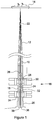
- a landing string assembly 10 is diagrammatically illustrated in Figure 1 , shown in use within a riser 12 and extending between a surface vessel 14 and a subsea wellhead assembly 16 which includes a BOP 18 mounted on a wellhead 20.
- the use and functionality of landing strings are well known in the art for through-riser deployment of equipment, such as completion architecture, well testing equipment, intervention tooling and the like into a subsea well from a surface vessel.
- the landing string 10 When in a deployed configuration the landing string 10 extends through the riser 12 and into the BOP 18. While deployed the landing string 10 provides many functions, including permitting the safe deployment of wireline or coiled tubing equipment (not shown) through the landing string and into the well, providing the necessary primary well control barriers and permitting emergency disconnect while isolating both the well and landing string 10.
- Wireline or coiled tubing deployment may be facilitated via a lubricator valve 22 which is located proximate the surface vessel 14.
- valves typically ball valves
- the valve suite includes a lower valve assembly called the subsea test tree valve (SSTT valve or SSTT) 24 which provides a safety barrier to contain well pressure, and also functions to cut any wireline or coiled tubing which extends through the landing string 10.
- the valve suite also includes an upper valve assembly called the retainer valve 26 which isolates the landing string contents and can be used to vent trapped pressure from between the retainer valve 26 and SSTT valve 24.
- a shear sub component 28 extends between the retainer valve 26 and SSTT valve 24 which is capable of being sheared by shear rams 30 of the BOP 18 if required.
- a slick joint 32 extends below the SSTT 24 which facilitates engagement with BOP pipe rams 34.
- the landing string 10 may include an interface arrangement for interfacing with other oil filed equipment.
- the landing string 10 includes a tubing hanger 36 at its lowermost end which engages with a corresponding tubing hanger 38 provided in the wellhead 20.
- the weight of the lower string (such as a completion, workover string or the like which extends into the well and thus not illustrated) becomes supported through the wellhead 20.
- all the weight and other forces associated with the lower string must be entirely supported through the landing string 10.
- the landing string 10 when deployed a degree of tension is conventionally applied to the landing string 10, for example to prevent adverse compressive forces being applied, for example due to the weight of the landing string 10, which can be significant in deep water.
- the landing string 10 must thus be designed to accommodate significant in-service loadings, such as the global tension and bending loads from a supported lower string.
- in-service loadings which may also include valve actuation loading, internal and external pressures and the like, must be accommodated across the various valve assemblies, such as the SSTT 24. It is therefore necessary to design the valve housings and appropriate end connections to be capable of accommodating the global applied tension, bending loads, valve actuation loading, pressures and the like.
- FIG. 2 A cross sectional view of a ball valve in accordance with an embodiment of the present invention is shown in Figure 2 .
- the ball valve may be provided for various functions, but for the purposes of the present description the ball valve may define a SSTT valve 24 of the landing string 10 shown in Figure 1 .
- the SSTT valve 24 is illustrated in Figure 1 as a dual ball valve, the arrangement shown in Figure 2 is a single ball valve assembly for purposes of clarity.
- the ball valve 24 includes a housing, generally identified by reference numeral 40 which is secured between the upper shear sub component 28 and the lower slick joint 32.
- the ball valve 24 is installed in-line with the landing string 10 which can be considered to be a fluid conduit system.
- the housing 40 accommodates a ball seat 42 and a ball member 44, wherein the ball member 44 is rotatable about axis 46 to selectively close the ball valve 24 and control flow through the landing string 10.
- the ball member 44 is rotatable in the direction of arrow 48 to close the ball valve 24.
- the ball seat 42 and ball member 44 define respective through bores 50, 52 which when aligned define a flow path through the valve 24 and when misaligned (as shown in Figure 2 ) prevent or restrict flow through the valve.
- a sealing area 54 is defined between the ball seal 42 and ball member 44.
- a leading edge surface 56 of the ball member 44 is configured to cut through a body (not shown), such as wireline, coiled tubing or the like which extends through the valve 24 and landing string 10 ( Figure 1 ) upon closure of the ball member 44.
- a body such as wireline, coiled tubing or the like which extends through the valve 24 and landing string 10 ( Figure 1 ) upon closure of the ball member 44.
- a housing 40 is configured to be mechanically secured in-line with the landing string 10 ( Figure 1 ).
- the housing 40 comprises a generally cylindrical member which extends between axially opposing end flange connectors 64, 66 which are secured to flange components 68, 70 of the shear sub 28 and slick joint 32, respectively.
- the housing 40 is designed to accommodate mechanical forces, such as axial and bending forces, associated with the landing string 10 and those of any supported lower string.
- the housing 40 also provides pressure containment of any and all internal and/or external pressures.
- the housing may be a two part or split housing comprising an outer housing and an inner housing.
- the outer housing may primarily be designed to connect the valve with the landing string and provide the required structural strength for the ball valve.
- the inner housing may be designed to provide pressure containment.
- the housing 40 of the valve 24 includes opposing flange connectors 64, 66 which are secured to the respective flange components 68, 70 of the shear sub 28 and slick joint 32.
- Each flange connection 64, 68 and 66, 70 may be made via a plurality of bolts.
- One or more of the bolts may be pre-tensioned to provide a degree of preloading through the connections.
- the ball valve further includes an actuator assembly, generally identified by reference numeral 72 for use in actuating the ball member 44 to rotate relative to the ball seat 42 between open and closed positions.
- the actuator assembly 72 comprises a piston arrangement, however it should be understood that many other actuators may be used without departing from the scope of the present invention.
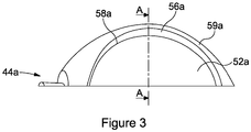
- Figure 3 shows a perspective view of an upper half of a ball member identified generally by reference numeral 44a, according to an exemplary embodiment of the present invention.
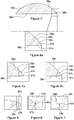
- Figure 4 shows a cross-sectional view of the ball member 44a of Figure 3 taken along line A-A.
- Figures 3 to 4a have many features in common with features shown in Figure 2 and as such like features share like reference numerals, suffixed with the letter "a”.
- the ball member 44a defines a through bore 52a.
- the ball member 44a further comprises a sealing surface 59a, a bore surface 58a, and a leading edge surface 56a extending between the sealing and bore surfaces.
- the leading edge surface 56a is truncated, as can be seen in Figure 4 .
- the truncated leading edge surface 56a comprises a first edge 51a defined at the interface of the truncated leading edge surface 56a with the bore surface 58a, and a second edge 53a defined at the interface of the truncated leading edge surface 56a with the sealing surface 59a.
- An intermediate surface 57a is defined between the first and second cutting edges 51a and 53a.
- leading edge surface 56a is flat or planar however, other configurations may also be used such as for example substantially flat or slightly curved.
- the truncated leading edge surface 56a is perpendicular or substantially perpendicular to the bore surface.
- the truncated leading edge surface may be sloped relative to the bore surface 58a forming an obtuse or an acute angle a with the bore surface as diagrammatically illustrated in Figures 4b and 4c , respectively.
- Figures 4b and 4c share many features in common with Figure 4a and for ease of reference similar features are denoted using similar numerals but with a suffix b or c, respectively in place of the suffix a.
- Figures 5-7 employ ball member having a slightly sloped truncated leading edge surface 57b as shown in the enlarged view of Figure 4b .
- the leading edge surface 56b is configured to engage with and cut through a body, such as coiled tubing 78b, as shown in Figures 5 to 7 .
- the body 78b extends via through bore 52b of the ball member 44b and through bore 50b of the ball seat 42b.
- rotation of the ball member 44b towards a closed position causes conveyance 78b to be engaged between an edge of the ball seat 45b and the first cutting edge 51b of the leading edge surface 56b of the ball member.
- the ball member 44b first engages the conveyance 78b at a first cutting edge 51b.
- the intermediate surface 57b is believed to provide space for the conveyance 78b to bend over the cutting edge 51b, thus facilitating the shearing action.
- Further rotation of the ball member 44b effects cutting of the coiled tubing 78b, primarily by a shearing action as shown in Figures 6 and 7 .
- Seal 43b may be any type of many well-known ball valve seat seal designs such as an O-ring seal or the like. It should be understood that other seal types may be used. According to one embodiment the sealing between the seat and the sealing surface of the ball member may be a metal to metal seal.
- the seat 42b of the ball valve may comprise a bore edge surface 47b that is flat (not shown) or it may include a slightly raised end portion 49b as shown in Figures 6 and 7 to further allow the conveyance 78b to bend during cutting.
- FIG. 8 and 8a another aspect of the present invention is illustrated.
- the ball member of Figures 8 and 8a has many features in common with the ball member shown in Figures 4 and 4a and as such like features share like reference numerals, augmented by 100.
- the ball valve according to another aspect of the present invention comprises a ball member 144a as shown in Figures 8 and 8a .
- the ball member 144a comprises a sealing surface 159a, a bore surface 158a and a leading edge surface 156a extending between the sealing surface 159a and the bore surface 158a.
- the ball member 144a further comprises a relief region 180a disposed immediately above the leading edge surface 156a.
- the relief region 180a is configured to accommodate a damaged or distorted leading edge surface 156a so that it may prevent it from scraping or damaging the seat.
- leading edge surface 156a is configured to engage with and cut through a body 178a, such as coiled tubing.
- the body 178a extends via through bore 152a of the ball member 144a and through bore 150a of the ball seat 142a.
- Seal 143a may be any type of many well-known ball valve seat seal designs such as an O-ring seal or the like. It should be understood that other seal types may be used. According to one embodiment the sealing between the seat and the sealing surface of the ball member may be a metal to metal seal.
- the seat 142a of the ball valve may comprise a bore edge surface 147a that is flat (not shown) or it may include a slightly raised end portion 149a as shown in Figures 10 and 11 to allow the conveyance 178a to bend during cutting.
- relief region 180a may accommodate any slight damage to the leading edge surface 156a thus preventing interference with the sealing functionality of the valve.
- the relied region 180a should be positioned in an area of the ball member that is proximate to the leading edge surface 156a but without interfering with the sealing upon full closure of the ball member.
- a relief region is provided in conjunction with a non-truncated leading edge surface.
- a ball valve is provided having a ball member 244a having both a relief region 280a and a truncated leading edge surface 256a.
- a relief region 280 is disposed immediately adjacent a truncated leading edge surface 256a.
- Leading edge surface 256a is perpendicular to the bore surface 258a, however, as discussed earlier, the leading edge surface may be sloped at an angle a relative to the bore.
- the angle a may be an obtuse or acute angle as shown in Figures 12b and 12c respectively.
- Figures 12b and 12c share many features in common with Figure 12a and thus we use the same numerals to denote similar features but with suffix b or c, respectively, in place of the suffix a used in respect with Figure 12a .
- the ball member 244a comprises a sealing surface 259a, a bore surface 258a and a leading edge surface 256a extending between the sealing surface 259a and the bore surface 258a.
- the ball member 244a further comprises a relief region 280a disposed immediately above the leading edge surface 256a.
- the relief region 280a is configured to accommodate a damaged or distorted leading edge surface 256a so that it may prevent it from scraping or damaging the seat.
- leading edge surface 256a in the embodiment shown in 12 is also truncated. This relief region and the truncated leading edge surface may be better seen in Figure 12a which provides an enlarged view of the boxed section of Figure 12 .
- the truncated leading edge surface 256a comprises a first edge 251a defined at the interface of the truncated leading edge surface 256a with the bore surface 258a, and a second edge 253a defined at the interface of the truncated leading edge surface 256a with the sealing surface 259a.
- An intermediate surface 257a is defined between the first and second cutting edges 251a and 253a.
- a relief region 280a forms a generally oval shape recess on the sealing surface of the ball member at a position immediately adjacent the edge 253a of the leading edge surface 256a.
- leading edge surface 256a according to the embodiment shown in Figures 12 and 12a is flat or planar however, other configurations may also be used such as for example substantially flat or slightly curved.
- the truncated leading edge surface 256a is perpendicular or substantially perpendicular to the bore surface 258a.
- the truncated leading edge surface may be sloped relative to the bore surface 258a forming an obtuse or an acute angle a with the bore surface as diagrammatically illustrated in Figures 12b and 12c , respectively.
- Figures 12b and 12c share many features in common with Figure 12a and for ease of reference similar features are denoted using similar numerals but with a suffix b or c, respectively in place of the suffix a.
- rotation of the ball member 244c towards a closed position causes conveyance 278c to be engaged between an edge of the ball seat 245c and the first cutting edge 251c of the leading edge surface 256c of the ball member.
- the ball member 244c first engages the conveyance 278c at a cutting edge 253c.
- the intermediate surface 257c is believed to provide space for the conveyance 278c to bend over the cutting edge 253c, thus facilitating the shearing action.
- Further rotation of the ball member 244c effects cutting of the coiled tubing 278c, primarily by a shearing action as shown in Figures 14 and 15 .
- Seal 243c may be any type of many well-known ball valve seat seal designs such as an O-ring seal or the like. It should be understood that other seal types may be used. According to one embodiment the sealing between the seat and the sealing surface of the ball member may be a metal to metal seal. Importantly relief region 280c may be disposed so that upon closure of the ball member will not interfere with the sealing area between the sealing surface of the ball member and the seat seal 243c. In the embodiment shown in Figures 13-15 upon full closure of the ball member 244c the relief region 280c is positioned below the seal 243c.
- the seat 242c of the ball valve may comprise a bore edge surface 247c that is flat (not shown) or it may include a slightly raised end portion 249c as shown in Figures 14 and 15 to further allow the conveyance 278c to bend during cutting.
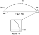
- a method for applying a coating to the sealing surface 359 of the ball valve member 344 comprises masking the leading edge surface 356 and bore surface 358 with a suitable masking material 390 and applying a coating using a high velocity oxy-fuel (HVOF) method. (IS THIS CORRECT) to the sealing surface 359. The mask is then removed from the bore surface 58 and the leading edge surface 56.
- HVOF high velocity oxy-fuel
- FIG. 17a and 17b another embodiment of the method of applying a coating is depicted.
- the method applies a coating to the sealing surface 459, as well as the leading edge surface 459, but excluding the relief region 480.
- This method comprises masking the relief region 480 as well as the bore surface 458 with a suitable masking material 490.
- a coating is then applied using HVOF to the sealing surface 459 and the leading edge surface 456.
- the mask is then removed from the bore surface 458 and the relief region 480.
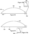
- FIG. 18 to 19 Yet another embodiment of the method of applying a coating is illustrated in Figures 18 to 19 .
- This method comprises masking the sealing surface 559 with a suitable masking material 590. Care should be applied to ensure the leading edge surface 556 remains unmasked.
- a coating using a gas plasma nitride (GPN) method, is then applied to the leading edge surface 556 and the bore surface 58.
- the mask is then removed from the sealing surface 59, and a masking material 690 is applied to the leading edge surface 556 and the bore surface 558, to completely cover them.
- a coating using HVOF is applied on the unmasked sealing surface 559. Following the application of the coating to the sealing surface 559, the mask is removed and the ball valve member 544 is ready for use.
- the sealing area of the ball member may comprise a first coating designed primarily to enhance the sealing functionality of the sealing surface, whereas the leading edge surface may comprise a second coating designed primarily to enhance its shearing capability.
- Any suitable coating or coatings may be used.
- a class of coatings that are particularly suitable are tungsten carbide coatings.
- Preferred coatings include tungsten carbide coatings marketed under the trade names PS-1005 and PS-1138 by Hardide Coatings.
- Coatings may be applied to the leading edge surface 556, sealing surface 559 or bore surface 558 for reasons other than to improve their working properties; for example, increase their resistance to corrosion or erosion.
- the housing defines a generally cylindrical outer profile.
- a non-cylindrical outer profile may be provided.
- an oval outer profile may be provided as may be needed for permitting other components such as a umbilical to be accommodated between the valve and an outer constraining component, such as a riser.
- valve embodiments described herein are merely exemplary and that various modifications may be made thereto without departing form the scope of the present invention.
- the disclosed valve embodiments are not solely for use within a landing string, and may be used in many other applications as would be understood by a person of skill in the art.
- the truncated leading edge surface ball valve also be used in combination with different valve types, and is not limited solely for use in ball valve applications, although defined and specific advantages do exist in such ball valve applications.
Landscapes
- Engineering & Computer Science (AREA)
- Geology (AREA)
- Life Sciences & Earth Sciences (AREA)
- Mining & Mineral Resources (AREA)
- Environmental & Geological Engineering (AREA)
- Fluid Mechanics (AREA)
- Physics & Mathematics (AREA)
- General Life Sciences & Earth Sciences (AREA)
- Geochemistry & Mineralogy (AREA)
- General Engineering & Computer Science (AREA)
- Mechanical Engineering (AREA)
- Taps Or Cocks (AREA)
- Details Of Valves (AREA)
Description
- The present invention relates to a ball valve configured for shearing a body upon closure. The present invention in particular, but not exclusively, relates to a ball valve for use in a landing string arrangement, for example for use within a subsea test tree.
- Landing strings are used in the oil and gas industry for through-riser deployment of equipment, such as completion architecture, well testing equipment, intervention tooling and the like into a subsea well from a surface vessel. When in a deployed configuration the landing string extends between the surface vessel and the wellhead, for example a wellhead Blow Out Preventor (BOP). While deployed the landing string provides many functions, including permitting the safe deployment of wireline or coiled tubing equipment through the landing string and into the well, providing the necessary primary well control barriers and permitting emergency disconnect while isolating both the well and landing string.
- Wireline or coiled tubing deployment may be facilitated via a lubricator valve which is located proximate the surface vessel, for example below a rig floor.
- Well control and isolation in the event of an emergency disconnect is provided by a suite of valves, typically ball valves, which are located at a lower end of the landing string, normally positioned inside the central bore of the BOP. The valve suite includes a lower valve assembly called the subsea test tree (SSTT) valve which provides a safety barrier to contain well pressure, and an upper valve assembly called the retainer valve which isolates the landing string contents and can be used to vent trapped pressure from between the retainer valve and SSTT valve. A shear sub component extends between the retainer valve and SSTT which is capable of being sheared by the BOP if required.
- As noted above, the landing string may accommodate wireline and/or coiled tubing deployed tools. In this respect the various valve assemblies, such as in the SSTT, must define sufficiently large internal diameters to permit unrestricted passage of the tools therethrough. In addition, the valve assemblies also have outer diameter limitations, as they should be locatable within a wellhead BOP. Such strict design requirements may create difficulties. For example, achieving appropriate valve sealing may be difficult, because increasing the internal diameter within a restricted outer diameter may only permit a reduced sealing area to be provided.
- Furthermore, the landing string must be capable of cutting any wireline or coiled tubing which extends therethrough in the event of an emergency disconnect. It is known in the art to use one or more of the valves to shear through the wireline or coiled tubing upon closure.
- However, providing a valve with the necessary cutting capacity may be difficult to achieve within the geometric design constraints of a landing string. For example, valve actuators must be of sufficient size to provide the necessary closing/cutting forces, which may be difficult to accommodate within the restricted available size.
- Furthermore, in ball valve applications a ball is provided with a through bore, wherein an edge of the through bore functions to cut through wireline or coiled tubing upon rotation of the ball towards a closed configuration. Known ball valves have circular through bores with generally pointed cutting edges, similar to a knife's cutting edge. Such ball valves tend to exhibit diminished sealing capability after one or more shearing operations. It is believed that this is at least partially because such pointed cutting edges tend to get slightly damaged after use. A damaged cutting edge may then interfere with the sealing functionality of the ball valve. For example, it has been observed that a slightly damaged cutting edge may scrape the seat and thus may compromise the sealing achieved between a sealing surface of the ball member and a seat of the ball valve. Thus, to ensure effective sealing after a shearing operation at least two conventional ball valves may have to be used, a first valve primarily designed to cut and a second valve designed to seal.
- Another problem with existing ball valve designs is that when used to cut hollow conveyances such as coiled tubing, the cutting forces are applied initially centrally of the tubing, causing the tubing to collapse, making subsequent shearing of the collapsed tube difficult and energy/force intensive.
-
US 8,662,183 discloses a blow-out preventer which includes a rotatable tubing cutter with a serrated cutting edge.US 2014/0116717 discloses a valve system which includes a valve element which carries a cutter.US 2014/0174755 discloses a valve which includes a ball valve member having a recessed cutting region. - The term "invention" is used throughout the present description with the loose meaning of "disclosure". The "invention", in the meaning of the combination of features for which protection is sought, is defined in the appended claims.
- According to a first aspect of the present invention there is provided a ball valve comprising:
- a housing;
- a ball seat arranged in the housing;
- a ball member mounted within the housing and being rotatable relative to the ball seat between open and closed positions;
- the ball seat and ball member defining respective through bores;
- the ball member comprising a sealing surface, a bore surface and a leading edge surface extending between the sealing surface and the bore surface, the leading edge surface being configured to cut a body extending at least partially through the valve upon closure of the ball member;
- wherein the leading edge surface is truncated.
- The respective through bores of the ball seat and ball member may define a flow path through the valve. The ball member may be rotated relative to the ball seat to misalign the respective through bores to prevent or restrict flow through the valve, and may be rotated relative to the ball seat to align, for example coaxially align, the respective through bores to permit or increase flow through the valve.
- In use, closure of the ball member to prevent or restrict flow through the valve may also result in any body which at least partially extends through the valve being cut, for example partially or fully cut. This arrangement may permit full closure of the valve member to be achieved without being obstructed from the body.
- The ball valve may have numerous applications as might readily be understood by those of skill in the art.
- The ball valve may be used in an in riser system.
- The ball valve may be used in an open water system.
- In some embodiments the ball valve may be configured for use within a landing string assembly. For example, the ball valve may define or form part of a SSTT valve, a retainer valve, a lubricator valve or the like. According to a preferred embodiment of the present invention the ball valve may be a SSTT valve. The housing of the SSTT valve may be configured to be located within a blow out preventor (BOP). BOP's are well known in the industry.
- It is believed that by employing a truncated leading edge surface it is less likely that any damage or deformation to the leading edge surface may damage the valve seat or the sealing surface of the ball member.
- The truncated leading edge surface of the ball member may be configured to cut an elongate body including at least one of tubing, coiled tubing, wireline, slickline, a tool string or the like.
- The truncated leading edge surface may comprise:
- a first edge defined at the interface of the truncated leading edge surface with the bore surface;
- a second edge defined at the interface of the truncated leading edge surface with the sealing surface; and
- an intermediate surface defined between the first and second edges.
- The leading edge surface may be planar or substantially planar. Alternatively, the leading edge surface may be curved. Other geometries may also be employed without departing from the scope of the present invention.
- The truncated leading edge surface may be perpendicular relative to the bore surface.
- The truncated leading edge surface may be sloped at an angle relative to the bore surface.
- The truncated leading edge surface may be sloped at an obtuse angle relative to the bore surface.
- The truncated leading edge surface may be sloped at an acute angle relative to the bore surface.
- The optimum angle for a particular application may depend on the relative dimensions of the ball member and the conveyance to be cut as well as the nature of the conveyance i.e. whether or not it is a hollow conveyance such as coiled tubing or a solid conveyance such as wireline.
- The first edge may be a cutting edge.
- The second edge may be a cutting edge.
- According to one embodiment both the first and second edges are cutting edges.
- It is believed that placing the truncated leading surface at an angle to the bore surface may allow initial engagement of the body to be cut at either the first or second cutting edge depending on the relative angle of the leading edge surface to the bore surface. This single point initial engagement may reduce the overall pressure exerted on the body to be cut which may prevent the collapsing observed with hollow conveyances such as coiled tubing.
- According to one embodiment the angle is selected to allow initial engagement of the body to be cut at the first cutting edge.
- Having a truncated leading edge surface at an angle to the bore surface may further be advantageous as it may provide additional void volume between the leading edge surface and a corresponding seat of the valve to allow any slight deformation of the leading edge surface to occur without adversely affecting the sealing capability of the ball member and/or the seat.
- The intermediate surface between the first and second edges may also contribute to the shearing functionality of the leading edge surface. For example, upon initial engagement of the body to be cut by said first or second cutting edge the intermediate surface may also engage the body further enhancing the shearing of the body.
- The intermediate surface may be flat or substantially flat.
- The intermediate surface may be curved.
- The intermediate surface may comprise one or more serrations.
- The leading edge surface may be an integral part of the ball member. For example, the leading edge surface may be machined to the desired truncated configuration.
- The leading edge surface may be or comprise an insert or an add-on member. The insert or an add-on member may be securely attached to a truncated edge of the ball member, for example by welding or any other suitable techniques. Such insert or add-on member may define a cutting edge.
- Such insert or add-on member may facilitate easier customization, maintenance and the like. For example, after use to re-establish a sufficient cutting edge only the insert need be replaced, rather than the entire ball. Also, the ball valve may be readily customized for the task at hand by mounting a suitable leading edge surface.
- The leading edge surface may be made of the same material as the remaining of the ball member.
- The leading edge surface may be made of a different material than the remaining of the ball member.
- The ball valve member may comprise a relief region disposed proximate the truncated leading edge surface.
- The relief region may be disposed immediate adjacent the truncated leading edge surface.
- The relief region may be disposed above and/or below the truncated leading edge surface.
- The relief region may be configured to accommodate slight damage or deformation to the truncated leading edge surface.
- The relief region may prevent a deformed leading edge surface from scraping or scoring the seat of the ball valve.
- The relief region may prolong the useful life of the ball valve by reducing sealing problems typically encountered after a shearing operation of the valve.
- The seat of the ball valve may comprise a bore edge surface that is flat or substantially flat.
- The seat may comprise a bore edge surface that is curved.
- Employing a seat with a slightly curved bore edge surface may be advantageous for facilitating shearing.
- The ball valve according to an embodiment of the invention may comprise a seat comprising a bore edge surface having a slightly raised end portion to allow a body to be cut to bend or deform over the raised portion during cutting. The raised portion may in essence operate as a fulcrum point to allow the body to be cut to bend or deform over the raised edge to thereby facilitate cutting. This may be particularly advantageous with hollow conveyances such as coiled tubing. It is observed that employing a seat with a raised end portion provides a fulcrum point for the body to be cut which facilitates shearing.
- The seat may comprise a seal which upon closure of the ball member mates with a corresponding sealing area defined on the sealing surface of the ball member to seal the ball member through bore. The seal may be any well-known suitable seat seal. The seal may be an O-ring seal or the like. The seal may be a metal to metal seal.
- The ball member may define a sealing area which may be part or the whole of the sealing surface which cooperates with an appropriate sealing area of the ball seat, at least when the valve is in a closed configuration. This sealing area may be specially treated to improve its sealing function.
- The ball member may comprise one or more coatings.
- The sealing area of the ball member may comprise a first coating to enhance sealing.
- The leading edge surface may comprise a second coating to enhance its shearing capability.
- The first and second coatings may be the same or different coatings.
- Any suitable coating or coatings may be used. A class of coatings that are particularly suitable are tungsten carbide coatings. Preferred coatings include tungsten carbide coatings marketed under the trade names PS-1005 and PS-1138 by Hardide Coatings.
- According to one embodiment, a first coating may be applied to at least a part of the sealing surface and a second different coating is applied to at least a part of the leading edge surface. The first coating may be any suitable coating for enhancing the sealing capability of the treated sealing surface. The second coating may be any suitable coating for enhancing the hardness and shearing capability of the treated leading edge surface.
- The coating or coatings may be applied by masking a section of the ball member that is not to be coated and then applying the coating to the remaining unmasked surfaces of the ball member.
- The coating or coatings may be applied via high velocity oxy-fuel coating (HVOF) spraying. However other well-known techniques may also be used.
- According to one embodiment a coating is applied to the leading edge surface using a gas plasma nitride (GPN) method.
- Masking of the ball member may be achieved by using any suitable masking material and techniques. Upon completion of the application of the coating or coatings the mask is then removed.
- The housing may be configured to be secured in-line with a fluid conduit system, wherein the ball seat and ball member may cooperate to control flow along the fluid conduit system. The fluid conduit system may be defined by one or more tubing components, flow equipment such as other valves, flow meters, shear-sub components or the like. The housing may be configured to be secured in-line with a landing string.
- The housing may comprise first and second connectors for securing in-line with a fluid conduit system, such as a landing string. At least one of the first and second connectors may comprise a flange connector, such as a bolted flange connector. The first and second connectors may be configured to be secured to a similar component, such as tubing, for example. The first and second connectors may be configured to be secured to different components. For example, one connector may be configured to be secured to tubing, and one connector may be configured to be secured to flow equipment such as another valve or the like.
- The housing may comprise a unitary component.
- Alternatively, the housing may comprise two or more components.
- The ball valve may comprise a plurality of respective ball seats and ball members. Such an arrangement may provide a degree of redundancy within the ball valve.
- According to a second aspect of the present invention there is provided a ball valve comprising:
- a housing;
- a ball seat arranged in the housing;
- a ball member mounted within the housing and being rotatable relative to the ball seat between open and closed positions;
- the ball seat and ball member defining respective through bores;
- the ball member comprising a sealing surface, a bore surface, a leading edge surface extending between the sealing surface and the bore surface, the leading edge surface being configured to cut a body extending at least partially through the valve upon closure of the ball member;
- wherein the ball member comprises a relief region disposed proximate the leading edge surface.
- The relief region may accommodate a damaged or deformed leading edge surface to prevent the damaged or deformed leading edge surface from negatively interfering with the sealing functionality of the ball valve. For example, the relief region may prevent a damaged or deformed leading edge surface from scraping the seat. The relief region may be disposed adjacent or immediate adjacent the truncated leading edge surface.
- The relief region may be disposed above or below the truncated leading edge surface the terms below and above made to reference to the configuration of the ball valve when in use.
- The leading edge surface may be pointed, rounded or truncated. According to one embodiment, the leading edge surface may be truncated or comprise a truncated portion. All the features described in connection with the first aspect of the invention may also be used with the second aspect of the invention.
- According to a third aspect of the present invention there is provided a method for isolating a fluid conduit system having a body extending internally therethrough, the method comprising:
- securing a ball valve in-line within the fluid conduit system, wherein the ball valve comprises a housing, a ball seat arranged in the housing and a ball member mounted within the housing and being rotatable relative to the ball seat between open and closed positions, wherein the ball seat and ball member define respective through bores;
- the ball member comprising a sealing surface, a bore surface and a leading edge surface extending between the sealing surface and the bore surface, the leading edge surface being configured to cut a body extending at least partially through the valve upon closure of the ball member wherein said leading edge surface is truncated; and
- rotating the ball member to close the valve and to cut a body extending at least partially through the valve with the truncated leading edge surface.
- Yet according to another aspect of the present invention there is provided a method for isolating a fluid conduit system having a body extending internally therethrough, the method comprising:
- securing a ball valve in-line within the fluid conduit system, wherein the ball valve comprises a housing, a ball seat arranged in the housing and a ball member mounted within the housing and being rotatable relative to the ball seat between open and closed positions, wherein the ball seat and ball member define respective through bores, the ball member comprising a sealing surface, a bore surface and a leading edge surface extending between the sealing surface and the bore surface, the leading edge surface being configured to cut a body extending at least partially through the valve upon closure of the ball member wherein the ball member comprises a relief region proximate the leading edge surface to accommodate damage to the leading edge surface to prevent the leading edge surface from scraping the seat; and
- rotating the ball member to close the valve and to cut a body extending at least partially through the valve with the leading edge surface.
- According to yet another aspect of the present invention there is provided a landing string assembly comprising at least one ball valve having the features of the ball valve according to the first and/or second aspects of the present invention.
- According to yet another aspect of the present invention there is provided a ball member having any of the features of the first and second aspects of the present invention and which is suitable for use with a ball valve.
- According to an aspect of the present invention there is provided a ball member for a ball valve, the ball member comprising:
- a sealing surface, a bore surface and a leading edge surface extending between the sealing surface and the bore surface, the leading edge surface being configured to cut a body extending at least partially through the valve upon closure of the ball member;
- wherein the leading edge surface is truncated.
- The truncated leading edge surface may have any of the features described above.
- In yet another aspect of the invention there is provided a ball member for a ball valve the ball member comprising:
- the ball member comprising a sealing surface, a bore surface, a leading edge surface extending between the sealing surface and the bore surface, the leading edge surface being configured to cut a body extending at least partially through the valve upon closure of the ball member;
- wherein the ball member comprises a relief region disposed proximate the leading edge surface.
- The leading edge surface and the relief region may have any of the features described in relation to any other aspect of the invention.
- Features defined in relation to one aspect defined above may be associated with any other aspect.
- These and other aspects of the present invention will now be described, by way of example only, with reference to the accompanying drawings, in which:
-
Figure1 is a simplified schematic illustration of a landing string according to one embodiment of the present invention. -
Figure 2 is a simplified cross sectional view of a ball valve according to one embodiment of the invention. -
Figure 3 is a simplified perspective view of an upper half section of a ball valve member according to one embodiment of the invention. -
Figure 4 is a simplified cross sectional view of one half of a ball member with a truncated edge taken along axis A-A offigure 3 . -
Figure 4a is an enlarged view of the boxed section ofFigure 4 . -
Figures 4b and 4c are enlarged views of the boxed section ofFigure 4 showing obtusely and acutely angled leading edge surfaces, respectively, according to different embodiments of the invention. -
Figure 5 shows an enlarged cross sectional view of a truncated leading edge surface of a ball member pressed against a body just prior to being cut. -
Figure 6 shows the truncated leading edge surface ofFigure 5 in a position immediately after cutting a body in relation to a corresponding seat, according to an embodiment of the invention. -
Figure 7 shows the truncated leading edge surface ofFigure 6 in the fully closed position after having severed a section of tubing, according to one embodiment of the invention. -
Figure 8 is a simplified cross sectional view of one half of a ball member with a relief section, according to one embodiment of the invention. -
Figure 8a is an enlarged view of the boxed section ofFigure 8 . -
Figure 9 shows an enlarged cross sectional view of a ball member with a relief region showing a leading edge surface of the ball member pressed against a body just prior to being cut, according to an embodiment of the invention. -
Figure 10 shows the leading edge surface ofFigure 9 in a position immediately after cutting a body in relation to a corresponding seat, according to one embodiment of the invention. -
Figure 11 shows the leading edge surface ofFigure 10 in a fully closed position after having severed a body, according to one embodiment of the invention. -
Figure 12 shows a simplified cross sectional view of one half of a ball member with a truncated leading edge surface and a relief section, according to one embodiment of the invention. -
Figure 12a is an enlarged view of the boxed section of the ball member ofFigure 12 . -
Figures 12b and 12c are enlarged views of the boxed section ofFigure 12 showing obtusely and acutely angled leading edge surfaces, respectively, according to different embodiments of the invention. -
Figure 13 shows an enlarged cross sectional view of a truncated leading edge surface of a ball member also having a relief region, pressed against a body just prior to it being cut, according to one embodiment of the invention. -
Figure 14 shows the truncated leading edge surface of the ball member ofFigure 13 in a position immediately after cutting a body in relation to the seat, according to one embodiment of the invention. -
Figure 15 shows the truncated leading edge surface of the ball member ofFigure 14 in a fully closed position after having severed a body, according to one embodiment of the invention. -
Figures 16a and 16b are simplified cross sectional views of one half of a ball valve member showing the application of a coating on the sealing surface, according to one embodiment of the invention. -
Figures 17a and 17b are simplified cross sectional views of one half of a ball valve member showing the application of a coating on the sealing surface and leading edge surface, according to one embodiment of the invention. -
Figures 18 to 19b are simplified cross sectional views of one half of a ball valve member showing the application of a coating on the leading edge surface, sealing surface and bore surface according to one embodiment of the invention. - A landing
string assembly 10 is diagrammatically illustrated inFigure 1 , shown in use within ariser 12 and extending between asurface vessel 14 and asubsea wellhead assembly 16 which includes aBOP 18 mounted on awellhead 20. The use and functionality of landing strings are well known in the art for through-riser deployment of equipment, such as completion architecture, well testing equipment, intervention tooling and the like into a subsea well from a surface vessel. - When in a deployed configuration the
landing string 10 extends through theriser 12 and into theBOP 18. While deployed thelanding string 10 provides many functions, including permitting the safe deployment of wireline or coiled tubing equipment (not shown) through the landing string and into the well, providing the necessary primary well control barriers and permitting emergency disconnect while isolating both the well andlanding string 10. - Wireline or coiled tubing deployment may be facilitated via a
lubricator valve 22 which is located proximate thesurface vessel 14. - Well control and isolation in the event of an emergency disconnect is provided by a suite of valves, typically ball valves, which are located at a lower end of the
landing string 10 inside the BOP. The valve suite includes a lower valve assembly called the subsea test tree valve (SSTT valve or SSTT) 24 which provides a safety barrier to contain well pressure, and also functions to cut any wireline or coiled tubing which extends through the landingstring 10. The valve suite also includes an upper valve assembly called theretainer valve 26 which isolates the landing string contents and can be used to vent trapped pressure from between theretainer valve 26 andSSTT valve 24. Ashear sub component 28 extends between theretainer valve 26 andSSTT valve 24 which is capable of being sheared byshear rams 30 of theBOP 18 if required. A slick joint 32 extends below theSSTT 24 which facilitates engagement with BOP pipe rams 34. - The landing
string 10 may include an interface arrangement for interfacing with other oil filed equipment. For example, in the present embodiment thelanding string 10 includes atubing hanger 36 at its lowermost end which engages with acorresponding tubing hanger 38 provided in thewellhead 20. When thelanding string 10 is fully deployed and thecorresponding tubing hangers wellhead 20. However, during deployment of the lower string through theriser 12 all the weight and other forces associated with the lower string must be entirely supported through the landingstring 10. Furthermore, when deployed a degree of tension is conventionally applied to thelanding string 10, for example to prevent adverse compressive forces being applied, for example due to the weight of thelanding string 10, which can be significant in deep water. The landingstring 10 must thus be designed to accommodate significant in-service loadings, such as the global tension and bending loads from a supported lower string. Such in-service loadings, which may also include valve actuation loading, internal and external pressures and the like, must be accommodated across the various valve assemblies, such as theSSTT 24. It is therefore necessary to design the valve housings and appropriate end connections to be capable of accommodating the global applied tension, bending loads, valve actuation loading, pressures and the like. - A cross sectional view of a ball valve in accordance with an embodiment of the present invention is shown in
Figure 2 . The ball valve may be provided for various functions, but for the purposes of the present description the ball valve may define aSSTT valve 24 of thelanding string 10 shown inFigure 1 . It should be noted that although theSSTT valve 24 is illustrated inFigure 1 as a dual ball valve, the arrangement shown inFigure 2 is a single ball valve assembly for purposes of clarity. - Referring now to
Figure 2 , theball valve 24 includes a housing, generally identified byreference numeral 40 which is secured between the uppershear sub component 28 and the lower slick joint 32. As such, theball valve 24 is installed in-line with the landingstring 10 which can be considered to be a fluid conduit system. Thehousing 40 accommodates aball seat 42 and aball member 44, wherein theball member 44 is rotatable aboutaxis 46 to selectively close theball valve 24 and control flow through the landingstring 10. In the embodiment shown theball member 44 is rotatable in the direction ofarrow 48 to close theball valve 24. Theball seat 42 andball member 44 define respective throughbores valve 24 and when misaligned (as shown inFigure 2 ) prevent or restrict flow through the valve. When theball member 44 is closed a sealingarea 54 is defined between theball seal 42 andball member 44. - A
leading edge surface 56 of theball member 44 is configured to cut through a body (not shown), such as wireline, coiled tubing or the like which extends through thevalve 24 and landing string 10 (Figure 1 ) upon closure of theball member 44. - A
housing 40 is configured to be mechanically secured in-line with the landing string 10 (Figure 1 ). Thehousing 40 comprises a generally cylindrical member which extends between axially opposingend flange connectors flange components shear sub 28 and slick joint 32, respectively. Thehousing 40 is designed to accommodate mechanical forces, such as axial and bending forces, associated with the landingstring 10 and those of any supported lower string. Thehousing 40 also provides pressure containment of any and all internal and/or external pressures. - Various types of housings may be employed without departing from the scope of the present invention. For example, the housing may be a two part or split housing comprising an outer housing and an inner housing. In such an arrangement the outer housing may primarily be designed to connect the valve with the landing string and provide the required structural strength for the ball valve. The inner housing may be designed to provide pressure containment.
- The
housing 40 of thevalve 24 includes opposingflange connectors respective flange components shear sub 28 and slick joint 32. Eachflange connection - The ball valve further includes an actuator assembly, generally identified by
reference numeral 72 for use in actuating theball member 44 to rotate relative to theball seat 42 between open and closed positions. In the present example, theactuator assembly 72 comprises a piston arrangement, however it should be understood that many other actuators may be used without departing from the scope of the present invention. - Reference is now made to
Figures 3 to 4a which illustrate in simplified schematic form a first aspect of the present invention.Figure 3 shows a perspective view of an upper half of a ball member identified generally byreference numeral 44a, according to an exemplary embodiment of the present invention.Figure 4 shows a cross-sectional view of theball member 44a ofFigure 3 taken along line A-A.Figures 3 to 4a have many features in common with features shown inFigure 2 and as such like features share like reference numerals, suffixed with the letter "a". - Referring now to
Figure 3 , theball member 44a defines a throughbore 52a. Theball member 44a further comprises a sealingsurface 59a, abore surface 58a, and aleading edge surface 56a extending between the sealing and bore surfaces. - The
leading edge surface 56a is truncated, as can be seen inFigure 4 . As it can be better seen inFigure 4a which is an enlarged view of the boxed section ofFigure 4 , the truncatedleading edge surface 56a comprises afirst edge 51a defined at the interface of the truncatedleading edge surface 56a with thebore surface 58a, and asecond edge 53a defined at the interface of the truncatedleading edge surface 56a with the sealingsurface 59a. Anintermediate surface 57a is defined between the first andsecond cutting edges - The
leading edge surface 56a according to the embodiment shown inFigures 3 to 4a is flat or planar however, other configurations may also be used such as for example substantially flat or slightly curved. - The truncated
leading edge surface 56a, as shown inFigures 4 and 4a , is perpendicular or substantially perpendicular to the bore surface. However, the truncated leading edge surface may be sloped relative to thebore surface 58a forming an obtuse or an acute angle a with the bore surface as diagrammatically illustrated inFigures 4b and 4c , respectively.Figures 4b and 4c share many features in common withFigure 4a and for ease of reference similar features are denoted using similar numerals but with a suffix b or c, respectively in place of the suffix a. - The operation of a ball valve of the present invention will now be described in reference to
Figures 5 to 7. Figures 5-7 employ ball member having a slightly sloped truncated leadingedge surface 57b as shown in the enlarged view ofFigure 4b . - Referring now to
Figures 5 to 7 , the leadingedge surface 56b is configured to engage with and cut through a body, such ascoiled tubing 78b, as shown inFigures 5 to 7 . Thebody 78b extends via throughbore 52b of the ball member 44b and throughbore 50b of theball seat 42b. - In operation, rotation of the ball member 44b towards a closed position causes
conveyance 78b to be engaged between an edge of theball seat 45b and thefirst cutting edge 51b of theleading edge surface 56b of the ball member. Thus, according to the embodiment shown inFigures 5 to 7 the ball member 44b first engages theconveyance 78b at afirst cutting edge 51b. Theintermediate surface 57b is believed to provide space for theconveyance 78b to bend over thecutting edge 51b, thus facilitating the shearing action. Further rotation of the ball member 44b effects cutting of the coiledtubing 78b, primarily by a shearing action as shown inFigures 6 and 7 . - Once the ball member is fully closed, a seal is formed between the sealing surface of the ball member and the bore edge surface of the seat facilitated further by a
seal member 43b secured to theseat member 42b.Seal 43b may be any type of many well-known ball valve seat seal designs such as an O-ring seal or the like. It should be understood that other seal types may be used. According to one embodiment the sealing between the seat and the sealing surface of the ball member may be a metal to metal seal. - The
seat 42b of the ball valve may comprise abore edge surface 47b that is flat (not shown) or it may include a slightly raisedend portion 49b as shown inFigures 6 and 7 to further allow theconveyance 78b to bend during cutting. - Referring now to
Figures 8 and 8a another aspect of the present invention is illustrated. The ball member ofFigures 8 and 8a has many features in common with the ball member shown inFigures 4 and 4a and as such like features share like reference numerals, augmented by 100. - The ball valve according to another aspect of the present invention comprises a
ball member 144a as shown inFigures 8 and 8a . Theball member 144a comprises a sealingsurface 159a, abore surface 158a and aleading edge surface 156a extending between the sealingsurface 159a and thebore surface 158a. Theball member 144a further comprises arelief region 180a disposed immediately above the leadingedge surface 156a. Therelief region 180a is configured to accommodate a damaged or distorted leadingedge surface 156a so that it may prevent it from scraping or damaging the seat. - It has been observed that after operation of a ball valve to cut a conveyance the sealing capability of the ball valve may be thereafter compromised. The applicant has discovered that by introducing a relief region adjacent the leading edge surface the sealing operation of the ball valve may, following a cutting, operation, improve substantially. The
leading edge surface 156a in the embodiment shown in 8 is not truncated, but it has a smoothly curved pointed shape. This can better be seen inFigure 8 which provides an enlarged view of the boxed section ofFigure 8 . - The operation of a ball valve having a ball member with a relief region and a smoothly curved pointed shape leading edge surface is shown diagrammatically in
Figures 9 to 11 . - Referring now to
Figures 9 to 11 , the leadingedge surface 156a is configured to engage with and cut through abody 178a, such as coiled tubing. Thebody 178a extends via through bore 152a of theball member 144a and throughbore 150a of the ball seat 142a. - In operation, rotation of the
ball member 144a towards a closed position causesconveyance 178a to be engaged between an edge of the ball seat 145a and theleading edge surface 156a of theball member 144a. Thus, according to the embodiment shown inFigures 9 to 11 theball member 144a first engages theconveyance 178a at theleading edge surface 156a. Further rotation of theball member 144a effects cutting of the coiledtubing 178a, primarily by a shearing action as shown inFigures 10 and 11 . - Once the ball member is fully closed, a seal is formed between the sealing surface of the ball member and the bore edge surface of the seat facilitated further by a
seal member 143a secured to the seat member 142a.Seal 143a may be any type of many well-known ball valve seat seal designs such as an O-ring seal or the like. It should be understood that other seal types may be used. According to one embodiment the sealing between the seat and the sealing surface of the ball member may be a metal to metal seal. - The seat 142a of the ball valve may comprise a
bore edge surface 147a that is flat (not shown) or it may include a slightly raisedend portion 149a as shown inFigures 10 and 11 to allow theconveyance 178a to bend during cutting. - It is believed that
relief region 180a may accommodate any slight damage to theleading edge surface 156a thus preventing interference with the sealing functionality of the valve. The reliedregion 180a should be positioned in an area of the ball member that is proximate to theleading edge surface 156a but without interfering with the sealing upon full closure of the ball member. - In the embodiment of
Figure 8 a relief region is provided in conjunction with a non-truncated leading edge surface. However, it in yet another embodiment if the present invention as illustrated inFigure 12 a ball valve is provided having aball member 244a having both arelief region 280a and a truncatedleading edge surface 256a. - The ball valve of
Figures 12 and 12a has many features in common with the ball valve shown inFigures 4 and 4a and as such like features augmented with 200. Referring now toFigure 12 , a relief region 280 is disposed immediately adjacent a truncatedleading edge surface 256a. Leadingedge surface 256a is perpendicular to thebore surface 258a, however, as discussed earlier, the leading edge surface may be sloped at an angle a relative to the bore. The angle a may be an obtuse or acute angle as shown inFigures 12b and 12c respectively.Figures 12b and 12c share many features in common withFigure 12a and thus we use the same numerals to denote similar features but with suffix b or c, respectively, in place of the suffix a used in respect withFigure 12a . - Referring now to
Figure 12 the ball valve according to another aspect of the present invention comprises aball member 244a. Theball member 244a comprises a sealingsurface 259a, abore surface 258a and aleading edge surface 256a extending between the sealingsurface 259a and thebore surface 258a. Theball member 244a further comprises arelief region 280a disposed immediately above the leadingedge surface 256a. Therelief region 280a is configured to accommodate a damaged or distorted leadingedge surface 256a so that it may prevent it from scraping or damaging the seat. - The
leading edge surface 256a in the embodiment shown in 12 is also truncated. This relief region and the truncated leading edge surface may be better seen inFigure 12a which provides an enlarged view of the boxed section ofFigure 12 . - Referring now to
Figure 12a , the truncatedleading edge surface 256a comprises afirst edge 251a defined at the interface of the truncatedleading edge surface 256a with thebore surface 258a, and asecond edge 253a defined at the interface of the truncatedleading edge surface 256a with the sealingsurface 259a. Anintermediate surface 257a is defined between the first andsecond cutting edges relief region 280a forms a generally oval shape recess on the sealing surface of the ball member at a position immediately adjacent theedge 253a of theleading edge surface 256a. - The
leading edge surface 256a according to the embodiment shown inFigures 12 and 12a is flat or planar however, other configurations may also be used such as for example substantially flat or slightly curved. - The truncated
leading edge surface 256a, as shown inFigures 12 and 12a , is perpendicular or substantially perpendicular to thebore surface 258a. However, the truncated leading edge surface may be sloped relative to thebore surface 258a forming an obtuse or an acute angle a with the bore surface as diagrammatically illustrated inFigures 12b and 12c , respectively.Figures 12b and 12c share many features in common withFigure 12a and for ease of reference similar features are denoted using similar numerals but with a suffix b or c, respectively in place of the suffix a. - The operation of a ball valve having a
ball member 244c with arelief region 280c and a truncatedleading edge surface 256a as shown inFigure 12c is illustrated in inFigures 13 to 15 . - In operation, rotation of the
ball member 244c towards a closed position causesconveyance 278c to be engaged between an edge of theball seat 245c and thefirst cutting edge 251c of the leading edge surface 256c of the ball member. Thus, according to the embodiment shown inFigures 13 to 15 theball member 244c first engages theconveyance 278c at acutting edge 253c. Theintermediate surface 257c is believed to provide space for theconveyance 278c to bend over thecutting edge 253c, thus facilitating the shearing action. Further rotation of theball member 244c effects cutting of the coiledtubing 278c, primarily by a shearing action as shown inFigures 14 and 15 . - Once the ball member is fully closed, a seal is formed between the sealing surface of the ball member and the bore edge surface of the seat facilitated further by a
seal member 243c secured to theseat member 242c.Seal 243c may be any type of many well-known ball valve seat seal designs such as an O-ring seal or the like. It should be understood that other seal types may be used. According to one embodiment the sealing between the seat and the sealing surface of the ball member may be a metal to metal seal. Importantlyrelief region 280c may be disposed so that upon closure of the ball member will not interfere with the sealing area between the sealing surface of the ball member and theseat seal 243c. In the embodiment shown inFigures 13-15 upon full closure of theball member 244c therelief region 280c is positioned below theseal 243c. - The
seat 242c of the ball valve may comprise abore edge surface 247c that is flat (not shown) or it may include a slightly raisedend portion 249c as shown inFigures 14 and 15 to further allow theconveyance 278c to bend during cutting. - Referring to
Figures 16a and 16b , a method for applying a coating to the sealingsurface 359 of theball valve member 344 is described. The method comprises masking theleading edge surface 356 and boresurface 358 with asuitable masking material 390 and applying a coating using a high velocity oxy-fuel (HVOF) method. (IS THIS CORRECT) to the sealingsurface 359. The mask is then removed from the bore surface 58 and theleading edge surface 56. - Referring now to
Figures 17a and 17b , another embodiment of the method of applying a coating is depicted. The method applies a coating to the sealingsurface 459, as well as the leadingedge surface 459, but excluding the relief region 480. This method comprises masking the relief region 480 as well as thebore surface 458 with asuitable masking material 490. A coating is then applied using HVOF to the sealingsurface 459 and theleading edge surface 456. The mask is then removed from thebore surface 458 and the relief region 480. - Yet another embodiment of the method of applying a coating is illustrated in
Figures 18 to 19 . This method comprises masking the sealingsurface 559 with asuitable masking material 590. Care should be applied to ensure theleading edge surface 556 remains unmasked. In this version, a coating, using a gas plasma nitride (GPN) method, is then applied to theleading edge surface 556 and the bore surface 58. The mask is then removed from the sealing surface 59, and a maskingmaterial 690 is applied to theleading edge surface 556 and thebore surface 558, to completely cover them. Then a coating using HVOF is applied on the unmasked sealingsurface 559. Following the application of the coating to the sealingsurface 559, the mask is removed and theball valve member 544 is ready for use. - For example the sealing area of the ball member may comprise a first coating designed primarily to enhance the sealing functionality of the sealing surface, whereas the leading edge surface may comprise a second coating designed primarily to enhance its shearing capability.
- Any suitable coating or coatings may be used. A class of coatings that are particularly suitable are tungsten carbide coatings. Preferred coatings include tungsten carbide coatings marketed under the trade names PS-1005 and PS-1138 by Hardide Coatings.
- Coatings may be applied to the
leading edge surface 556, sealingsurface 559 or boresurface 558 for reasons other than to improve their working properties; for example, increase their resistance to corrosion or erosion. - In the embodiments described above, the housing defines a generally cylindrical outer profile. However, in other embodiments a non-cylindrical outer profile may be provided. For example an oval outer profile may be provided as may be needed for permitting other components such as a umbilical to be accommodated between the valve and an outer constraining component, such as a riser.
- It should be understood that the embodiments described herein are merely exemplary and that various modifications may be made thereto without departing form the scope of the present invention. For example, the disclosed valve embodiments are not solely for use within a landing string, and may be used in many other applications as would be understood by a person of skill in the art. Furthermore, the truncated leading edge surface ball valve also be used in combination with different valve types, and is not limited solely for use in ball valve applications, although defined and specific advantages do exist in such ball valve applications.
Claims (13)
- A ball valve (24) comprising:a housing (40);a ball seat (42) arranged in the housing (40);a ball member (144a) mounted within the housing (40) and being rotatable relative to the ball seat (42) between open and closed positions;the ball seat (42) and ball member (144a) defining respective through bores (50);the ball member (144a) comprising a sealing surface (159a), a bore surface (158a), a leading edge surface (156a) extending between the sealing surface (159a) and the bore surface (158a), the leading edge surface being configured to cut a body extending at least partially through the valve (24) upon closure of the ball member (144a), characterised in that;the ball member (144a) comprises a relief region (189a) disposed proximate said leading edge surface (156a) such that the relief region (180a) is positioned between the leading edge surface (156a) and the sealing surface (159a).
- The ball valve (24) according to claim 1, wherein the respective through bores (50) of the ball seat (42) and ball member (144a) define a flow path through the valve (24), wherein the ball member (144a) is rotated relative to the ball seat (42) to misalign the respective through bores (50) to prevent or restrict flow through the valve (24), and is rotated relative to the ball seat (42) to align, for example coaxially align, the respective through bores (50) to permit or increase flow through the valve (24).
- The ball valve (24) according to claim 1 or 2, defining or forming part of at least one of a Subsea Test Tree (SSTT), a retainer valve and a lubricator valve.
- The ball valve (24) according to any preceding claim, wherein the leading edge surface (156a) is configured to cut an elongate body including at least one of tubing, coiled tubing, wireline, slickline and a tool string.
- The ball valve (24) according to any preceding claim, wherein the leading edge surface (156a) is truncated.
- The ball valve (24) according to claim 5, wherein the truncated leading edge surface (156a) is planar, substantially planar or slightly curved.
- The ball valve (24) according to claim 5 or 6, wherein the truncated leading edge surface (156a) is perpendicular relative to the bore surface (158a).
- The ball valve (24) according to claim 5 or 6, wherein the truncated leading edge surface (156a) is sloped at an angle relative to the bore surface (158a).
- The ball valve (24) according to claim 8, wherein the truncated leading edge surface (156a) is sloped at an obtuse angle relative to the bore surface (158a).
- The ball valve (24) according to claim 8, wherein the truncated leading edge surface (156a) is sloped at an acute angle relative to the bore surface (158a).
- The ball valve (24) according to any preceding claim, wherein the leading edge surface (156a) is an insert or an add-on member securely attached to the ball member (144a).
- The ball valve (24) according to any preceding claim, wherein the seat (42) comprises a bore edge (147a) having a raised portion to allow coiled tubing to bend during cutting.
- A ball member (144a) for a ball valve (24), the ball valve (24) comprising:a sealing surface (159a), a bore surface (158a), a leading edge surface (156a) extending between the sealing surface (159a) and the bore surface (158a), the leading edge surface (156a) being configured to cut a body extending at least partially through the valve (24) upon closure of the ball member (144a),characterised in that;the ball member (144a) comprises a relief region (180a) disposed proximate said leading edge surface (156a) such that the relief region (180a) is positioned between the leading edge surface (156a) and the sealing surface (159a).
Applications Claiming Priority (2)
| Application Number | Priority Date | Filing Date | Title |
|---|---|---|---|
| GBGB1500554.9A GB201500554D0 (en) | 2015-01-14 | 2015-01-14 | Ball valve |
| PCT/GB2015/053855 WO2016113525A1 (en) | 2015-01-14 | 2015-12-11 | Ball valve |
Publications (2)
| Publication Number | Publication Date |
|---|---|
| EP3245379A1 EP3245379A1 (en) | 2017-11-22 |
| EP3245379B1 true EP3245379B1 (en) | 2018-10-10 |
Family
ID=52597563
Family Applications (1)
| Application Number | Title | Priority Date | Filing Date |
|---|---|---|---|
| EP15813503.8A Active EP3245379B1 (en) | 2015-01-14 | 2015-12-11 | Ball valve |
Country Status (6)
| Country | Link |
|---|---|
| US (1) | US10450834B2 (en) |
| EP (1) | EP3245379B1 (en) |
| AU (1) | AU2015377817B2 (en) |
| CA (1) | CA2971537C (en) |
| GB (1) | GB201500554D0 (en) |
| WO (1) | WO2016113525A1 (en) |
Cited By (1)
| Publication number | Priority date | Publication date | Assignee | Title |
|---|---|---|---|---|
| US12638087B2 (en) | 2023-12-30 | 2026-05-26 | Ross J. Trewhella | Ball valves and processes of using same |
Families Citing this family (11)
| Publication number | Priority date | Publication date | Assignee | Title |
|---|---|---|---|---|
| GB201713253D0 (en) | 2017-08-18 | 2017-10-04 | Expro North Sea Ltd | Valve seat and valve |
| GB201812902D0 (en) | 2018-08-08 | 2018-09-19 | Expro North Sea Ltd | Subsea test tree assembly |
| GB2591401B (en) * | 2018-09-25 | 2022-08-24 | Schlumberger Technology Bv | Ball valve for improved performance in debris laden environments |
| EP4472240B1 (en) | 2019-02-07 | 2026-07-08 | Oticon A/s | A hearing device comprising an adjustable vent |
| CN110318708B (en) * | 2019-05-31 | 2021-07-23 | 西南石油大学 | A safety control device for a riserless drilling drill string |
| WO2020263963A1 (en) * | 2019-06-24 | 2020-12-30 | Onesubsea Ip Uk Limited | Ball valve assembly |
| GB201917311D0 (en) | 2019-11-28 | 2020-01-15 | Expro North Sea Ltd | A valve assembly |
| GB202107147D0 (en) | 2021-05-19 | 2021-06-30 | Expro North Sea Ltd | Control system for a well control device |
| GB202107620D0 (en) | 2021-05-28 | 2021-07-14 | Expro North Sea Ltd | Control system for a well control device |
| WO2024186875A1 (en) * | 2023-03-06 | 2024-09-12 | HEN Nozzles Inc. | Shut-off valve component |
| CN116241678B (en) * | 2023-03-21 | 2025-07-25 | 中海石油(中国)有限公司北京研究中心 | Multifunctional shearing ball valve |
Family Cites Families (15)
| Publication number | Priority date | Publication date | Assignee | Title |
|---|---|---|---|---|
| US3883113A (en) * | 1974-03-29 | 1975-05-13 | Acf Ind Inc | Fluid control ball valve structure for throttling service |
| US4009753A (en) * | 1976-03-22 | 1977-03-01 | Schlumberger Technology Corporation | Subsea master valve apparatus |
| US4289165A (en) * | 1979-05-17 | 1981-09-15 | Otis Engineering Corporation | Equalizing ball valve member |
| US4429717A (en) | 1981-09-04 | 1984-02-07 | Montgomery Robert N | Valve for controlling the flow of semi-liquid compositions |
| JPS59110964A (en) * | 1982-12-16 | 1984-06-27 | Sekisui Chem Co Ltd | Ball valve and manufacture thereof |
| US5413310A (en) * | 1991-07-12 | 1995-05-09 | Den Norske Stats Oljeselskap A.S | Valve arrangement |
| US5284209A (en) * | 1992-08-19 | 1994-02-08 | Halliburton Company | Coiled tubing cutting modification |
| US6152229A (en) * | 1998-08-24 | 2000-11-28 | Abb Vetco Gray Inc. | Subsea dual in-line ball valves |
| US20100051847A1 (en) * | 2008-09-04 | 2010-03-04 | Tejas Research And Engineering, Lp | Method and Apparatus for Severing Conduits |
| US8403063B2 (en) * | 2008-10-03 | 2013-03-26 | Halliburton Energy Services, Inc. | Downhole ball mechanism with enhanced drift clearance |
| US8662183B1 (en) * | 2011-02-12 | 2014-03-04 | Louis P. Vickio, Jr. | Blow out preventer |
| GB2493180A (en) * | 2011-07-27 | 2013-01-30 | Expro North Sea Ltd | Valve housing arrangement |
| US9410391B2 (en) * | 2012-10-25 | 2016-08-09 | Schlumberger Technology Corporation | Valve system |
| US20140209314A1 (en) * | 2013-01-28 | 2014-07-31 | Schlumberger Technology Corporation | Shear and seal system for subsea applications |
| WO2014130052A1 (en) * | 2013-02-25 | 2014-08-28 | Halliburton Energy Services, Inc. | Pressure equalization for dual seat ball valve |
-
2015
- 2015-01-14 GB GBGB1500554.9A patent/GB201500554D0/en not_active Ceased
- 2015-12-11 US US15/543,479 patent/US10450834B2/en active Active
- 2015-12-11 WO PCT/GB2015/053855 patent/WO2016113525A1/en not_active Ceased
- 2015-12-11 AU AU2015377817A patent/AU2015377817B2/en active Active
- 2015-12-11 EP EP15813503.8A patent/EP3245379B1/en active Active
- 2015-12-11 CA CA2971537A patent/CA2971537C/en active Active
Non-Patent Citations (1)
| Title |
|---|
| None * |
Cited By (1)
| Publication number | Priority date | Publication date | Assignee | Title |
|---|---|---|---|---|
| US12638087B2 (en) | 2023-12-30 | 2026-05-26 | Ross J. Trewhella | Ball valves and processes of using same |
Also Published As
| Publication number | Publication date |
|---|---|
| WO2016113525A1 (en) | 2016-07-21 |
| CA2971537A1 (en) | 2016-07-21 |
| AU2015377817A1 (en) | 2017-07-06 |
| US20170370180A1 (en) | 2017-12-28 |
| EP3245379A1 (en) | 2017-11-22 |
| US10450834B2 (en) | 2019-10-22 |
| CA2971537C (en) | 2023-10-03 |
| GB201500554D0 (en) | 2015-02-25 |
| AU2015377817B2 (en) | 2020-08-27 |
Similar Documents
| Publication | Publication Date | Title |
|---|---|---|
| CA2971537C (en) | Ball valve | |
| EP2142755B1 (en) | Oil well completion tool having severable tubings string barrier disc | |
| CA1265993A (en) | Tubing isolation disc valve | |
| EP3669105B1 (en) | Valve seat and valve | |
| EP3959415B1 (en) | Blowout preventer shearing ram | |
| EP2737165A2 (en) | Ball valve | |
| CN103174394A (en) | Ram bop shear blade process to enhance the toughness | |
| EP3545166B1 (en) | Gate valve | |
| AU2016269054B2 (en) | Wellbore control device | |
| US11286740B2 (en) | Blowout preventer shearing ram | |
| US8662183B1 (en) | Blow out preventer | |
| WO2016164256A1 (en) | High-strength blowout preventer shearing ram and connecting rod | |
| US20140174755A1 (en) | Valve | |
| EP2971466B1 (en) | Gate valve assembly comprising a support member | |
| US20150308211A1 (en) | Systems and Methods for Catastrophe Mitigation for Deep Water Oil Drilling during Blowout Preventer Failure | |
| WO2015155539A2 (en) | Valve assembly | |
| EP3533966B1 (en) | Improved shear blade |
Legal Events
| Date | Code | Title | Description |
|---|---|---|---|
| STAA | Information on the status of an ep patent application or granted ep patent |
Free format text: STATUS: THE INTERNATIONAL PUBLICATION HAS BEEN MADE |
|
| PUAI | Public reference made under article 153(3) epc to a published international application that has entered the european phase |
Free format text: ORIGINAL CODE: 0009012 |
|
| STAA | Information on the status of an ep patent application or granted ep patent |
Free format text: STATUS: REQUEST FOR EXAMINATION WAS MADE |
|
| 17P | Request for examination filed |
Effective date: 20170609 |
|
| AK | Designated contracting states |
Kind code of ref document: A1 Designated state(s): AL AT BE BG CH CY CZ DE DK EE ES FI FR GB GR HR HU IE IS IT LI LT LU LV MC MK MT NL NO PL PT RO RS SE SI SK SM TR |
|
| AX | Request for extension of the european patent |
Extension state: BA ME |
|
| DAV | Request for validation of the european patent (deleted) | ||
| DAX | Request for extension of the european patent (deleted) | ||
| GRAP | Despatch of communication of intention to grant a patent |
Free format text: ORIGINAL CODE: EPIDOSNIGR1 |
|
| STAA | Information on the status of an ep patent application or granted ep patent |
Free format text: STATUS: GRANT OF PATENT IS INTENDED |
|
| INTG | Intention to grant announced |
Effective date: 20180614 |
|
| RIN1 | Information on inventor provided before grant (corrected) |
Inventor name: DEACON, PAUL Inventor name: MANETT, KRIS |
|
| GRAS | Grant fee paid |
Free format text: ORIGINAL CODE: EPIDOSNIGR3 |
|
| GRAJ | Information related to disapproval of communication of intention to grant by the applicant or resumption of examination proceedings by the epo deleted |
Free format text: ORIGINAL CODE: EPIDOSDIGR1 |
|
| GRAL | Information related to payment of fee for publishing/printing deleted |
Free format text: ORIGINAL CODE: EPIDOSDIGR3 |
|
| STAA | Information on the status of an ep patent application or granted ep patent |
Free format text: STATUS: REQUEST FOR EXAMINATION WAS MADE |
|
| GRAR | Information related to intention to grant a patent recorded |
Free format text: ORIGINAL CODE: EPIDOSNIGR71 |
|
| STAA | Information on the status of an ep patent application or granted ep patent |
Free format text: STATUS: GRANT OF PATENT IS INTENDED |
|
| INTC | Intention to grant announced (deleted) | ||
| GRAA | (expected) grant |
Free format text: ORIGINAL CODE: 0009210 |
|
| STAA | Information on the status of an ep patent application or granted ep patent |
Free format text: STATUS: THE PATENT HAS BEEN GRANTED |
|
| INTG | Intention to grant announced |
Effective date: 20180830 |
|
| AK | Designated contracting states |
Kind code of ref document: B1 Designated state(s): AL AT BE BG CH CY CZ DE DK EE ES FI FR GB GR HR HU IE IS IT LI LT LU LV MC MK MT NL NO PL PT RO RS SE SI SK SM TR |
|
| REG | Reference to a national code |
Ref country code: GB Ref legal event code: FG4D |
|
| REG | Reference to a national code |
Ref country code: CH Ref legal event code: EP Ref country code: AT Ref legal event code: REF Ref document number: 1051466 Country of ref document: AT Kind code of ref document: T Effective date: 20181015 |
|
| REG | Reference to a national code |
Ref country code: IE Ref legal event code: FG4D |
|
| REG | Reference to a national code |
Ref country code: DE Ref legal event code: R096 Ref document number: 602015018048 Country of ref document: DE |
|
| REG | Reference to a national code |
Ref country code: NL Ref legal event code: MP Effective date: 20181010 |
|
| REG | Reference to a national code |
Ref country code: LT Ref legal event code: MG4D Ref country code: NO Ref legal event code: T2 Effective date: 20181010 |
|
| REG | Reference to a national code |
Ref country code: AT Ref legal event code: MK05 Ref document number: 1051466 Country of ref document: AT Kind code of ref document: T Effective date: 20181010 |
|
| PG25 | Lapsed in a contracting state [announced via postgrant information from national office to epo] |
Ref country code: NL Free format text: LAPSE BECAUSE OF FAILURE TO SUBMIT A TRANSLATION OF THE DESCRIPTION OR TO PAY THE FEE WITHIN THE PRESCRIBED TIME-LIMIT Effective date: 20181010 |
|
| PG25 | Lapsed in a contracting state [announced via postgrant information from national office to epo] |
Ref country code: IS Free format text: LAPSE BECAUSE OF FAILURE TO SUBMIT A TRANSLATION OF THE DESCRIPTION OR TO PAY THE FEE WITHIN THE PRESCRIBED TIME-LIMIT Effective date: 20190210 Ref country code: FI Free format text: LAPSE BECAUSE OF FAILURE TO SUBMIT A TRANSLATION OF THE DESCRIPTION OR TO PAY THE FEE WITHIN THE PRESCRIBED TIME-LIMIT Effective date: 20181010 Ref country code: LV Free format text: LAPSE BECAUSE OF FAILURE TO SUBMIT A TRANSLATION OF THE DESCRIPTION OR TO PAY THE FEE WITHIN THE PRESCRIBED TIME-LIMIT Effective date: 20181010 Ref country code: AT Free format text: LAPSE BECAUSE OF FAILURE TO SUBMIT A TRANSLATION OF THE DESCRIPTION OR TO PAY THE FEE WITHIN THE PRESCRIBED TIME-LIMIT Effective date: 20181010 Ref country code: HR Free format text: LAPSE BECAUSE OF FAILURE TO SUBMIT A TRANSLATION OF THE DESCRIPTION OR TO PAY THE FEE WITHIN THE PRESCRIBED TIME-LIMIT Effective date: 20181010 Ref country code: BG Free format text: LAPSE BECAUSE OF FAILURE TO SUBMIT A TRANSLATION OF THE DESCRIPTION OR TO PAY THE FEE WITHIN THE PRESCRIBED TIME-LIMIT Effective date: 20190110 Ref country code: PL Free format text: LAPSE BECAUSE OF FAILURE TO SUBMIT A TRANSLATION OF THE DESCRIPTION OR TO PAY THE FEE WITHIN THE PRESCRIBED TIME-LIMIT Effective date: 20181010 Ref country code: LT Free format text: LAPSE BECAUSE OF FAILURE TO SUBMIT A TRANSLATION OF THE DESCRIPTION OR TO PAY THE FEE WITHIN THE PRESCRIBED TIME-LIMIT Effective date: 20181010 Ref country code: ES Free format text: LAPSE BECAUSE OF FAILURE TO SUBMIT A TRANSLATION OF THE DESCRIPTION OR TO PAY THE FEE WITHIN THE PRESCRIBED TIME-LIMIT Effective date: 20181010 |
|
| PG25 | Lapsed in a contracting state [announced via postgrant information from national office to epo] |
Ref country code: AL Free format text: LAPSE BECAUSE OF FAILURE TO SUBMIT A TRANSLATION OF THE DESCRIPTION OR TO PAY THE FEE WITHIN THE PRESCRIBED TIME-LIMIT Effective date: 20181010 Ref country code: PT Free format text: LAPSE BECAUSE OF FAILURE TO SUBMIT A TRANSLATION OF THE DESCRIPTION OR TO PAY THE FEE WITHIN THE PRESCRIBED TIME-LIMIT Effective date: 20190210 Ref country code: GR Free format text: LAPSE BECAUSE OF FAILURE TO SUBMIT A TRANSLATION OF THE DESCRIPTION OR TO PAY THE FEE WITHIN THE PRESCRIBED TIME-LIMIT Effective date: 20190111 Ref country code: SE Free format text: LAPSE BECAUSE OF FAILURE TO SUBMIT A TRANSLATION OF THE DESCRIPTION OR TO PAY THE FEE WITHIN THE PRESCRIBED TIME-LIMIT Effective date: 20181010 Ref country code: RS Free format text: LAPSE BECAUSE OF FAILURE TO SUBMIT A TRANSLATION OF THE DESCRIPTION OR TO PAY THE FEE WITHIN THE PRESCRIBED TIME-LIMIT Effective date: 20181010 |
|
| REG | Reference to a national code |
Ref country code: DE Ref legal event code: R119 Ref document number: 602015018048 Country of ref document: DE |
|
| PG25 | Lapsed in a contracting state [announced via postgrant information from national office to epo] |
Ref country code: IT Free format text: LAPSE BECAUSE OF FAILURE TO SUBMIT A TRANSLATION OF THE DESCRIPTION OR TO PAY THE FEE WITHIN THE PRESCRIBED TIME-LIMIT Effective date: 20181010 Ref country code: CZ Free format text: LAPSE BECAUSE OF FAILURE TO SUBMIT A TRANSLATION OF THE DESCRIPTION OR TO PAY THE FEE WITHIN THE PRESCRIBED TIME-LIMIT Effective date: 20181010 Ref country code: DK Free format text: LAPSE BECAUSE OF FAILURE TO SUBMIT A TRANSLATION OF THE DESCRIPTION OR TO PAY THE FEE WITHIN THE PRESCRIBED TIME-LIMIT Effective date: 20181010 |
|
| REG | Reference to a national code |
Ref country code: CH Ref legal event code: PL |
|
| PLBE | No opposition filed within time limit |
Free format text: ORIGINAL CODE: 0009261 |
|
| STAA | Information on the status of an ep patent application or granted ep patent |
Free format text: STATUS: NO OPPOSITION FILED WITHIN TIME LIMIT |
|
| PG25 | Lapsed in a contracting state [announced via postgrant information from national office to epo] |
Ref country code: EE Free format text: LAPSE BECAUSE OF FAILURE TO SUBMIT A TRANSLATION OF THE DESCRIPTION OR TO PAY THE FEE WITHIN THE PRESCRIBED TIME-LIMIT Effective date: 20181010 Ref country code: MC Free format text: LAPSE BECAUSE OF FAILURE TO SUBMIT A TRANSLATION OF THE DESCRIPTION OR TO PAY THE FEE WITHIN THE PRESCRIBED TIME-LIMIT Effective date: 20181010 Ref country code: SM Free format text: LAPSE BECAUSE OF FAILURE TO SUBMIT A TRANSLATION OF THE DESCRIPTION OR TO PAY THE FEE WITHIN THE PRESCRIBED TIME-LIMIT Effective date: 20181010 Ref country code: LU Free format text: LAPSE BECAUSE OF NON-PAYMENT OF DUE FEES Effective date: 20181211 Ref country code: RO Free format text: LAPSE BECAUSE OF FAILURE TO SUBMIT A TRANSLATION OF THE DESCRIPTION OR TO PAY THE FEE WITHIN THE PRESCRIBED TIME-LIMIT Effective date: 20181010 Ref country code: SK Free format text: LAPSE BECAUSE OF FAILURE TO SUBMIT A TRANSLATION OF THE DESCRIPTION OR TO PAY THE FEE WITHIN THE PRESCRIBED TIME-LIMIT Effective date: 20181010 |
|
| 26N | No opposition filed |
Effective date: 20190711 |
|
| REG | Reference to a national code |
Ref country code: IE Ref legal event code: MM4A |
|
| REG | Reference to a national code |
Ref country code: BE Ref legal event code: MM Effective date: 20181231 |
|
| PG25 | Lapsed in a contracting state [announced via postgrant information from national office to epo] |
Ref country code: FR Free format text: LAPSE BECAUSE OF NON-PAYMENT OF DUE FEES Effective date: 20181231 Ref country code: SI Free format text: LAPSE BECAUSE OF FAILURE TO SUBMIT A TRANSLATION OF THE DESCRIPTION OR TO PAY THE FEE WITHIN THE PRESCRIBED TIME-LIMIT Effective date: 20181010 Ref country code: IE Free format text: LAPSE BECAUSE OF NON-PAYMENT OF DUE FEES Effective date: 20181211 Ref country code: DE Free format text: LAPSE BECAUSE OF NON-PAYMENT OF DUE FEES Effective date: 20190702 |
|
| PG25 | Lapsed in a contracting state [announced via postgrant information from national office to epo] |
Ref country code: BE Free format text: LAPSE BECAUSE OF NON-PAYMENT OF DUE FEES Effective date: 20181231 |
|
| PG25 | Lapsed in a contracting state [announced via postgrant information from national office to epo] |
Ref country code: CH Free format text: LAPSE BECAUSE OF NON-PAYMENT OF DUE FEES Effective date: 20181231 Ref country code: LI Free format text: LAPSE BECAUSE OF NON-PAYMENT OF DUE FEES Effective date: 20181231 |
|
| PG25 | Lapsed in a contracting state [announced via postgrant information from national office to epo] |
Ref country code: MT Free format text: LAPSE BECAUSE OF NON-PAYMENT OF DUE FEES Effective date: 20181211 |
|
| PG25 | Lapsed in a contracting state [announced via postgrant information from national office to epo] |
Ref country code: TR Free format text: LAPSE BECAUSE OF FAILURE TO SUBMIT A TRANSLATION OF THE DESCRIPTION OR TO PAY THE FEE WITHIN THE PRESCRIBED TIME-LIMIT Effective date: 20181010 |
|
| PG25 | Lapsed in a contracting state [announced via postgrant information from national office to epo] |
Ref country code: HU Free format text: LAPSE BECAUSE OF FAILURE TO SUBMIT A TRANSLATION OF THE DESCRIPTION OR TO PAY THE FEE WITHIN THE PRESCRIBED TIME-LIMIT; INVALID AB INITIO Effective date: 20151211 Ref country code: CY Free format text: LAPSE BECAUSE OF FAILURE TO SUBMIT A TRANSLATION OF THE DESCRIPTION OR TO PAY THE FEE WITHIN THE PRESCRIBED TIME-LIMIT Effective date: 20181010 Ref country code: MK Free format text: LAPSE BECAUSE OF NON-PAYMENT OF DUE FEES Effective date: 20181010 |
|
| P01 | Opt-out of the competence of the unified patent court (upc) registered |
Effective date: 20230512 |
|
| PGFP | Annual fee paid to national office [announced via postgrant information from national office to epo] |
Ref country code: GB Payment date: 20251001 Year of fee payment: 11 |
|
| PGFP | Annual fee paid to national office [announced via postgrant information from national office to epo] |
Ref country code: NO Payment date: 20251210 Year of fee payment: 11 |