EP3244696A1 - Method and apparatus for providing feedback in an isolated operating device for lighting - Google Patents
Method and apparatus for providing feedback in an isolated operating device for lighting Download PDFInfo
- Publication number
- EP3244696A1 EP3244696A1 EP16169281.9A EP16169281A EP3244696A1 EP 3244696 A1 EP3244696 A1 EP 3244696A1 EP 16169281 A EP16169281 A EP 16169281A EP 3244696 A1 EP3244696 A1 EP 3244696A1
- Authority
- EP
- European Patent Office
- Prior art keywords
- side circuit
- oscillating signal
- quantities
- primary side
- operating device
- Prior art date
- Legal status (The legal status is an assumption and is not a legal conclusion. Google has not performed a legal analysis and makes no representation as to the accuracy of the status listed.)
- Withdrawn
Links
- 238000000034 method Methods 0.000 title claims description 13
- 230000008878 coupling Effects 0.000 claims abstract description 21
- 238000010168 coupling process Methods 0.000 claims abstract description 21
- 238000005859 coupling reaction Methods 0.000 claims abstract description 21
- 238000002955 isolation Methods 0.000 claims abstract description 12
- 230000005855 radiation Effects 0.000 claims description 4
- 230000003595 spectral effect Effects 0.000 claims description 4
- 239000000523 sample Substances 0.000 abstract description 4
- 238000013507 mapping Methods 0.000 description 2
- 239000000969 carrier Substances 0.000 description 1
- 238000010276 construction Methods 0.000 description 1
- 238000012937 correction Methods 0.000 description 1
- 238000010586 diagram Methods 0.000 description 1
- 238000000295 emission spectrum Methods 0.000 description 1
- 238000005516 engineering process Methods 0.000 description 1
- 231100001261 hazardous Toxicity 0.000 description 1
- 239000000463 material Substances 0.000 description 1
- 238000012986 modification Methods 0.000 description 1
- 230000004048 modification Effects 0.000 description 1
- 238000012544 monitoring process Methods 0.000 description 1
- 230000003287 optical effect Effects 0.000 description 1
- 239000004065 semiconductor Substances 0.000 description 1
- 238000000926 separation method Methods 0.000 description 1
- 238000002604 ultrasonography Methods 0.000 description 1
Images


Classifications
-
- H—ELECTRICITY
- H05—ELECTRIC TECHNIQUES NOT OTHERWISE PROVIDED FOR
- H05B—ELECTRIC HEATING; ELECTRIC LIGHT SOURCES NOT OTHERWISE PROVIDED FOR; CIRCUIT ARRANGEMENTS FOR ELECTRIC LIGHT SOURCES, IN GENERAL
- H05B45/00—Circuit arrangements for operating light-emitting diodes [LED]
- H05B45/20—Controlling the colour of the light
- H05B45/24—Controlling the colour of the light using electrical feedback from LEDs or from LED modules
-
- H—ELECTRICITY
- H05—ELECTRIC TECHNIQUES NOT OTHERWISE PROVIDED FOR
- H05B—ELECTRIC HEATING; ELECTRIC LIGHT SOURCES NOT OTHERWISE PROVIDED FOR; CIRCUIT ARRANGEMENTS FOR ELECTRIC LIGHT SOURCES, IN GENERAL
- H05B45/00—Circuit arrangements for operating light-emitting diodes [LED]
- H05B45/10—Controlling the intensity of the light
- H05B45/12—Controlling the intensity of the light using optical feedback
-
- H—ELECTRICITY
- H05—ELECTRIC TECHNIQUES NOT OTHERWISE PROVIDED FOR
- H05B—ELECTRIC HEATING; ELECTRIC LIGHT SOURCES NOT OTHERWISE PROVIDED FOR; CIRCUIT ARRANGEMENTS FOR ELECTRIC LIGHT SOURCES, IN GENERAL
- H05B45/00—Circuit arrangements for operating light-emitting diodes [LED]
- H05B45/30—Driver circuits
- H05B45/37—Converter circuits
- H05B45/3725—Switched mode power supply [SMPS]
- H05B45/382—Switched mode power supply [SMPS] with galvanic isolation between input and output
Definitions
- the invention relates to operating devices for lighting that comprise galvanically isolated primary and secondary sides.
- the invention relates to the task of conveying feedback signals across said galvanic isolation.
- An operating device for lighting is an electronic device that converts input power taken from a power distribution network to output power that is suitable for light sources such as light-emitting diodes (LEDs).
- the operating device may be of the constant output type, configured to provide the light sources with constant current and/or constant voltage and/or constant power.
- the operating device may be of the controllable type, configured to provide the light sources with variable power to make the light sources emit light at variable intensity.
- the LED driver When the light sources are LEDs the operating device is frequently referred to as the LED driver.
- a LED driver of the controllable type is configured to provide the LEDs with variable current.
- the output voltage of a LED driver is typically allowed to vary so that it assumes the value determined by the sum of threshold voltages of LEDs coupled in series at the output.
- the voltage in the power distribution network is typically high enough to be hazardous to humans, like 230 V or 120 V AC.
- the output voltage of an operating device for lighting may be required to be low enough to avoid similar hazards.
- Such an operating device is frequently referred to as a SELV (Safety Extra Low Voltage; also Separation Extra Low Voltage) device.
- Galvanic isolation is required between the input and output sides of a SELV device, dividing the device into a primary side and a secondary side.
- One or more transformers convey electric energy from the primary side to the secondary side. In many cases there is also the need to convey feedback or other signals over the isolation, either from the secondary side to the primary side or in the opposite direction.
- An optoisolator is a DC-operated device, in which the amount of electric current flowing through the light-emitting diode on one side becomes reflected by the conductivity of the phototransistor on the other side. It can be used in digital mode, i.e. with sufficient difference between current either flowing or not flowing through the light-emitting diode, or in analog mode, in which the varying amount of current flowing through the light-emitting diode is detected through the analogously varying conductivity of the phototransistor.
- a signal transformer is an AC-operated device, in which the input current must vary in order to induce a similarly varying output current. Optoisolators are favoured in isolated LED drivers over signal transformers, because optoisolators are smaller and cheaper and also because their DC operation conforms more easily with the common use of DC signals in circuits of this kind.
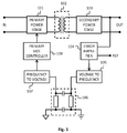
- FIG. 1 shows the suggested principle.
- a primary power stage 101 feeds power over a transformer 102 to the secondary power stage 102.
- An error amplifier 104 compares the output voltage to a reference and produces an amplified error voltage, which in turn defines the frequency of an oscillating signal in a first converter 105.
- a capacitive coupling 106 carries the oscillating signal back to the primary side, where it is converted into a voltage in a second converter 107. This voltage goes as a feedback signal to the primary side controller 108.
- an operating device for lighting It comprises:
- a method for providing feedback from a galvanically isolated secondary side circuit to a primary side circuit in an operating device for lighting comprises:
- Fig. 2 is a schematic illustration of an operating device for lighting. It comprises a primary side circuit 201, which is configured to receive electric power through an input a schematic representation of which is seen on the left in fig. 2 .
- the operating device comprises a secondary side circuit 203, which is galvanically isolated from the primary side circuit and configured to produce an output voltage and an output current.
- An output interface for coupling a lighting load such as a LED string or a LED module, is schematically shown on the right in fig. 2 .
- a transformer 202 is provided between the primary and secondary side circuits 201 and 203 for transferring electric power from the primary side circuit 201 to the secondary side circuit 203.
- the lighting load may comprise other kinds of light sources than LED, for example incandescent or fluorescent lights or lasers.
- the term LED is used here in general sense to mean all kinds of electroluminescent light sources in which the emission of light is caused by electrons recombining with holes within or close to semiconductor material.
- the operating device comprises a first detector 204 and a second detector 205 for probing first and second quantities in isolation from the primary side circuit 201 and for producing electric indications of detected values of the first and second quantities.
- the first and second quantities may be for example output voltage and output current, which may be probed directly or indirectly. Numerous ways of probing output voltage and output current, both directly and indirectly, are known from the technology of LED drivers.
- An example of directly probing output voltage involves a voltage divider coupled between an output voltage node and a local ground node, so that the potential difference between the middle point of the voltage divider and said local ground represents a scaled value of the actual output voltage.
- An example of directly probing output current involves a current sensing resistor on a current path that also carries (at least a significant portion of) the output current, so that the potential difference across the current probing resistor represents a scaled value of the actual output current.
- Indirect probing of output voltage and output current may involve various image quantities, like an image voltage or an image current, that are produced in unambiguous relation with the actual voltage or current of interest but are not literally the same.
- an electric indication of a detected value of a quantity is an electric signal, the magnitude of which has an unambiguous relation to the detected value of the probed quantity.
- an electric indication may be for example a voltage, the magnitude of which tells, how many milliamperes of electric current were detected.
- the electric indication of a detected value may be the value itself: for example if the detected value of a voltage is within a suitable range, it can be used as such as an electric indication. If the detected values of voltage are either too low or too high to be conveniently used as an electric indication, an electric indication of the detected voltage value may be obtained through scaling, for example with an amplifier or a voltage divider.
- Electric sensors of various kinds can be used to produce electric indications of detected values in a number of known ways, like producing a voltage that serves as an indication of detected value of temperature. Electric indications are not necessarily voltages; they can be any kinds of electrically expressed information.
- controllable oscillator circuit 206 that is coupled to the first 204 and second 205 detectors.
- the purpose of the controllable oscillator circuit 206 is to produce a common oscillating signal with at least two variable characteristics. Values of said at least two variable characteristics are controlled by above-mentioned electric indications of the detected values of the first and second quantities. Said at least two variable characteristics may be for example the frequency and duty cycle of the common oscillating signal.
- the operating device of fig. 2 comprises a galvanically isolated feedback coupling 207 for conveying the common oscillating signal from the secondary side circuit 203 to the primary side circuit 201.
- the primary side comprises a feedback decoding circuit 208, the task of which is to decode the information that the variable characteristics of the common oscillating signal conveyed over the galvanically isolated feedback coupling 207, i.e. to produce signals that enable the primary side circuit 201 to react properly to the detected values of the quantities monitored by the first and second detectors 204 and 205.
- the probed quantities include at least one of output voltage and output current
- knowing the detected values may prompt the primary side circuit 201 to increase or decrease the electric power that is transferred over the transformer 202.
- Fig. 3 illustrates schematically an embodiment in which the first detector 204 is a voltage divider coupled across the output of the operating device, and the second detector 205 comprises a sensing resistor in the output current path as well as an amplifier for amplifying the voltage across the sensing resistor.
- the controllable oscillator circuit comprises a voltage-controlled oscillator 301, here a VCSO (voltage-controlled sawtooth oscillator), which is configured to output a first oscillating signal 302.
- the frequency of the first oscillating signal 302 is defined by a control voltage 303.
- the electric indication of the first quantity i.e. the voltage provided by the first detector 204, constitutes said control voltage and thus defines the frequency of the first oscillating signal 302.
- the exemplary controllable oscillator circuit of fig. 3 comprises a comparator 304 configured to compare the first oscillating signal 302 to the electric indication of the second quantity, which is the output 305 of the amplifier in the second detector 205.
- the comparator 304 is thus configured to produce a two-level output signal 306 indicative of the result of comparing the first oscillating signal 302 to the output 305 of the amplifier in the second detector 205.
- the two-level output signal 306 is high as long as the output 305 of the amplifier in the second detector 205 remains higher than the momentary value of the first oscillating signal 302, and low otherwise.
- the polarity of the inputs of the comparator 304 could be selected in the opposite way, in which case the two-level output signal would be low as long as the output 305 of the amplifier in the second detector 205 remained higher than the momentary value of the first oscillating signal 302, and high otherwise.
- the two-level output signal 306 constitutes the common oscillating signal that is taken to the galvanically isolated feedback coupling 207, which in the exemplary embodiment of fig. 3 is an optoisolator.
- the upper part of fig. 4 illustrates an example of the first oscillating signal 302 and two arbitrarily selected levels of the output 305 of the amplifier in the second detector 205.
- the reference designator 305 refers to a relatively large value of the last-mentioned, meaning that the output current of the operating device is relatively high.
- the resulting form of the two-level output signal is shown with reference designator 306 in fig. 4 . It has a relatively high duty cycle, meaning that the two-level output signal 306 remains high for a relatively large proportion of each cycle.
- the reference designator 305' refers to a relatively small value of the output 305 of the amplifier in the second detector 205, meaning that the output current of the operating device is relatively low.
- the resulting form of the two-level output signal in this case is shown with reference designator 306' in fig. 4 . It has a relatively low duty cycle, meaning that the two-level output signal 306' remains high for a relatively small proportion of each cycle.
- the upper part of fig. 5 illustrates an example in which the frequency of the first oscillating signal is higher than in fig. 4 , for which reason it is shown with the reference designator 302".
- the illustrated level of the output 305 of the amplifier in the second detector is the same in fig. 5 as the similarly numbered level in fig. 4 .
- the resulting form of the two-level output signal is shown with reference designator 306" in fig. 5 .
- Its frequency is the same as that of the first oscillating signal 302”
- its duty cycle is the same as that shown with reference designator 306 in fig. 4 - both the "high” time and the "low” time in each cycle are shorter than of the two-level output signal 306 in fig. 4 , but their relation is the same.
- Figs. 3 to 5 thus illustrate an example of how the values of the at least two variable characteristics of the common oscillating signal are controlled by the electric indications of the detected values of the first and second quantities: the frequency of the common oscillating signal is controlled by the electric indication of the detected value of the output voltage, and the duty cycle of the common oscillating signal is controlled by the electric indication of the detected value of the output current.
- the first and second quantities that are probed in isolation from the primary side circuit are not necessarily electric quantities like output voltage and output current that are directly present within the secondary side circuit.
- At least one of the first and second detector may comprise a sensor configured to probe some other kind of quantity; such an "external" detector is schematically shown with reference designator 209 in fig. 2 .
- the "external" detector 209 may probe for example temperature, which may be a temperature within the operating device (in order to find out, whether the operating device is running within a safe temperature range), a temperature of the surroundings, or a temperature of the light sources coupled to the output of the operating device (in order to find out, whether the light sources are running within a safe temperature range, and/or whether a colour correction needs to be made because of a temperature-induced shift in an emission spectrum of the light sources).
- temperature may be a temperature within the operating device (in order to find out, whether the operating device is running within a safe temperature range), a temperature of the surroundings, or a temperature of the light sources coupled to the output of the operating device (in order to find out, whether the light sources are running within a safe temperature range, and/or whether a colour correction needs to be made because of a temperature-induced shift in an emission spectrum of the light sources).
- An “external” detector may also be used for so-called optical feedback, so that it probes the intensity and/or spectral content of light emitted by the light sources that are coupled to the output of the operating device.
- Yet another type of “external” detectors may involve receivers of wireless signals, in which case at least one of the first and second quantities could involve received infrared radiation, received ultrasound, or received wireless power.
- the two variable characteristics of the common oscillating signal were frequency and duty cycle.
- the encoding convention i.e. the way of mapping the probed quantities into the variable characteristics of the common oscillating signal, was such that the frequency of the common oscillating signal was proportional to the value of the output voltage, and the duty cycle of the common oscillating signal was proportional to the value of the output current.
- the concept of proportionality is used here in a more general sense than a strict mathematical interpretation; it means simply that the higher the output voltage the higher the frequency and so on.
- the encoding convention could be selected otherwise.
- the feedback decoding circuit 208 in the primary side circuit just needs to be constructed so that the information about the detected values of the probed quantities comes into appropriate use within the primary side circuit.
- Other variable characteristics of the common oscillating signal could be its amplitude and/or phase.
- the physical implementation of the galvanically isolated feedback coupling 207 must naturally be selected so that it accommodates the expected dynamic range of the variable characteristics of the common oscillating signal, and conveys the associated information with as little attenuation and distortion as possible. As soon as the character and dynamic range of the variable characteristics have been decided, a person skilled in the art can construct an adequate galvanically isolated feedback coupling in a relatively straightforward manner.
- the galvanically isolated feedback coupling 207 may comprise for example at least one of an optoisolator, signal transformer, and capacitive coupling.
- the galvanically isolated feedback coupling 207 may comprise a radio (or other short distance wireless) transmitter on the secondary side and a radio (or other short distance wireless) receiver on the primary side.
- the use of radio waves for feedback within a device is not very common, among others because all electromagnetic energy that may leak into the surroundings of the device is typically considered as unwanted interference and something that should be avoided.
- using radio waves for feedback within an operating device of a lighting system may involve surprising advantages. Namely, a lighting system typically involves a number of luminaires, each with its own operating device, within distances of some metres from each other. Certain kind of feedback transmitted in one of the operating devices may constitute useful information in another operating device nearby.
- a group of operating devices that are capable of monitoring the feedback transmitted in each other may develop a kind of swarm intelligence, so that for example feedback that asks for rapidly increasing power in one luminaire (because someone has entered the field of view of a PIR sensor, and lights need to be turned on) may trigger an increase of power also in other luminaires nearby, even before their own movement sensors detected the person in question.
- the schematic illustration in fig. 2 can also be considered as a functional diagram representing a method for providing feedback from a galvanically isolated secondary side circuit 203 to a primary side circuit 201 in an operating device for lighting.
- the method comprises:
- the first and second quantities may come from the group comprising output voltage, output current, temperature, intensity of light, spectral content of light, received infrared radiation, and received wireless power.
- Said at least two variable characteristics may come from the group comprising frequency of the common oscillating signal, duty cycle of the common oscillating signal, amplitude of the common oscillating signal, and phase of the common oscillating signal.
Landscapes
- Circuit Arrangement For Electric Light Sources In General (AREA)
Abstract
An operating device for lighting comprises a primary side circuit (201) configured to receive electric power and a secondary side circuit (203) galvanically isolated from the primary side circuit (201) and configured to produce an output voltage and an output current. A transformer (202) between said primary (201) and secondary (203) side circuits transfers electric power from the former to the latter. A first detector (204) and a second detector (205, 209) probe first and second quantities in isolation from said primary side circuit (201) and produce electric indications of detected values of said first and second quantities. A controllable oscillator circuit (206) produces a common oscillating signal with at least two variable characteristics, where-in values of said at least two variable characteristics are controlled by said electric indications of the detected values of said first and second quantities. A galvanically isolated feedback coupling (207) conveys said common oscillating signal from said secondary side circuit to said primary side circuit.
Description
- The invention relates to operating devices for lighting that comprise galvanically isolated primary and secondary sides. In particular the invention relates to the task of conveying feedback signals across said galvanic isolation.
- An operating device for lighting is an electronic device that converts input power taken from a power distribution network to output power that is suitable for light sources such as light-emitting diodes (LEDs). The operating device may be of the constant output type, configured to provide the light sources with constant current and/or constant voltage and/or constant power. Alternatively the operating device may be of the controllable type, configured to provide the light sources with variable power to make the light sources emit light at variable intensity. When the light sources are LEDs the operating device is frequently referred to as the LED driver. A LED driver of the controllable type is configured to provide the LEDs with variable current. The output voltage of a LED driver is typically allowed to vary so that it assumes the value determined by the sum of threshold voltages of LEDs coupled in series at the output.
- The voltage in the power distribution network is typically high enough to be hazardous to humans, like 230 V or 120 V AC. The output voltage of an operating device for lighting may be required to be low enough to avoid similar hazards. Such an operating device is frequently referred to as a SELV (Safety Extra Low Voltage; also Separation Extra Low Voltage) device. Galvanic isolation is required between the input and output sides of a SELV device, dividing the device into a primary side and a secondary side. One or more transformers convey electric energy from the primary side to the secondary side. In many cases there is also the need to convey feedback or other signals over the isolation, either from the secondary side to the primary side or in the opposite direction.
- The most common component types for conveying feedback or other signals across a galvanic isolation boundary are optoisolators and signal transformers. An optoisolator is a DC-operated device, in which the amount of electric current flowing through the light-emitting diode on one side becomes reflected by the conductivity of the phototransistor on the other side. It can be used in digital mode, i.e. with sufficient difference between current either flowing or not flowing through the light-emitting diode, or in analog mode, in which the varying amount of current flowing through the light-emitting diode is detected through the analogously varying conductivity of the phototransistor. A signal transformer is an AC-operated device, in which the input current must vary in order to induce a similarly varying output current. Optoisolators are favoured in isolated LED drivers over signal transformers, because optoisolators are smaller and cheaper and also because their DC operation conforms more easily with the common use of DC signals in circuits of this kind.
- A prior art publication
US 6,563,718 B1 explains the use of optoisolators and signal transformers but introduces also a third alternative, capacitive coupling.Fig. 1 shows the suggested principle. Aprimary power stage 101 feeds power over atransformer 102 to thesecondary power stage 102. An error amplifier 104 compares the output voltage to a reference and produces an amplified error voltage, which in turn defines the frequency of an oscillating signal in afirst converter 105. Acapacitive coupling 106 carries the oscillating signal back to the primary side, where it is converted into a voltage in asecond converter 107. This voltage goes as a feedback signal to theprimary side controller 108. - It is an object of the present invention to provide an operating device and a method for providing feedback from a galvanically isolated secondary side circuit to a primary side circuit of the operating device so that the arrangement is simple, reliable, and applicable to a number of different kinds of feedback schemes.
- The objects of the invention are reached by an apparatus and method as defined by the respective independent claims.
- According to a first aspect of the invention there is provided an operating device for lighting. It comprises:
- a primary side circuit configured to receive electric power,
- a secondary side circuit galvanically isolated from the primary side circuit and configured to produce an output voltage and an output current,
- a transformer between said primary and secondary side circuits for transferring electric power from the primary side circuit to the secondary side circuit,
- a first detector and a second detector for probing first and second quantities in isolation from said primary side circuit and for producing electric indications of detected values of said first and second quantities,
- within said secondary side circuit, a controllable oscillator circuit coupled to said first and second detectors for producing a common oscillating signal with at least two variable characteristics, where-in values of said at least two variable characteristics are controlled by said electric indications of the detected values of said first and second quantities, and
- a galvanically isolated feedback coupling for conveying said common oscillating signal from said secondary side circuit to said primary side circuit.
- According to a second aspect of the invention there is provided a method for providing feedback from a galvanically isolated secondary side circuit to a primary side circuit in an operating device for lighting. The method comprises:
- probing first and second quantities in isolation from said primary side circuit and producing electric indications of detected values of said first and second quantities,
- producing a common oscillating signal within said secondary side circuit with at least two variable characteristics, wherein values of said at least two variable characteristics are controlled by said electric indications of the detected values of said first and second quantities, and
- conveying said common oscillating signal through a galvanically isolated feedback coupling from said secondary side circuit to said primary side circuit.
- The exemplifying embodiments of the invention presented in this patent application are not to be interpreted to pose limitations to the applicability of the appended claims. The verb "to comprise" and its derivatives are used in this patent application as an open limitation that does not exclude the existence of also features that are not recited. The features described hereinafter are mutually freely combinable unless explicitly stated otherwise.
- The novel features which are considered as characteristic of the invention are set forth in particular in the appended claims. The invention itself, however, both as to its construction and its method of operation, together with additional objects and advantages thereof, will be best understood from the following detailed description of specific embodiments when read in connection with the accompanying drawings.
-
-
Figure 1 illustrates the known use of capacitive feedback coupling, -
figure 2 illustrates an apparatus according to an embodiment of the invention, -
figure 3 illustrates a controllable oscillator circuit, -
figure 4 illustrates the generation of a common oscillating signal in two different cases, and -
figure 5 illustrates the generation of a common oscillating signal in another case. -
Fig. 2 is a schematic illustration of an operating device for lighting. It comprises aprimary side circuit 201, which is configured to receive electric power through an input a schematic representation of which is seen on the left infig. 2 . The operating device comprises asecondary side circuit 203, which is galvanically isolated from the primary side circuit and configured to produce an output voltage and an output current. An output interface for coupling a lighting load, such as a LED string or a LED module, is schematically shown on the right infig. 2 . Atransformer 202 is provided between the primary andsecondary side circuits primary side circuit 201 to thesecondary side circuit 203. The lighting load may comprise other kinds of light sources than LED, for example incandescent or fluorescent lights or lasers. The term LED is used here in general sense to mean all kinds of electroluminescent light sources in which the emission of light is caused by electrons recombining with holes within or close to semiconductor material. - The operating device comprises a
first detector 204 and asecond detector 205 for probing first and second quantities in isolation from theprimary side circuit 201 and for producing electric indications of detected values of the first and second quantities. The first and second quantities may be for example output voltage and output current, which may be probed directly or indirectly. Numerous ways of probing output voltage and output current, both directly and indirectly, are known from the technology of LED drivers. An example of directly probing output voltage involves a voltage divider coupled between an output voltage node and a local ground node, so that the potential difference between the middle point of the voltage divider and said local ground represents a scaled value of the actual output voltage. An example of directly probing output current involves a current sensing resistor on a current path that also carries (at least a significant portion of) the output current, so that the potential difference across the current probing resistor represents a scaled value of the actual output current. Indirect probing of output voltage and output current may involve various image quantities, like an image voltage or an image current, that are produced in unambiguous relation with the actual voltage or current of interest but are not literally the same. - In the vocabulary of this description an electric indication of a detected value of a quantity is an electric signal, the magnitude of which has an unambiguous relation to the detected value of the probed quantity. As an example, while the value of an electric current is typically measured in milliamperes, an electric indication may be for example a voltage, the magnitude of which tells, how many milliamperes of electric current were detected. In some cases the electric indication of a detected value may be the value itself: for example if the detected value of a voltage is within a suitable range, it can be used as such as an electric indication. If the detected values of voltage are either too low or too high to be conveniently used as an electric indication, an electric indication of the detected voltage value may be obtained through scaling, for example with an amplifier or a voltage divider. Electric sensors of various kinds can be used to produce electric indications of detected values in a number of known ways, like producing a voltage that serves as an indication of detected value of temperature. Electric indications are not necessarily voltages; they can be any kinds of electrically expressed information.
- Within the
secondary side circuit 203 there is provided acontrollable oscillator circuit 206 that is coupled to the first 204 and second 205 detectors. The purpose of thecontrollable oscillator circuit 206 is to produce a common oscillating signal with at least two variable characteristics. Values of said at least two variable characteristics are controlled by above-mentioned electric indications of the detected values of the first and second quantities. Said at least two variable characteristics may be for example the frequency and duty cycle of the common oscillating signal. - The operating device of
fig. 2 comprises a galvanicallyisolated feedback coupling 207 for conveying the common oscillating signal from thesecondary side circuit 203 to theprimary side circuit 201. The primary side comprises afeedback decoding circuit 208, the task of which is to decode the information that the variable characteristics of the common oscillating signal conveyed over the galvanicallyisolated feedback coupling 207, i.e. to produce signals that enable theprimary side circuit 201 to react properly to the detected values of the quantities monitored by the first andsecond detectors primary side circuit 201 to increase or decrease the electric power that is transferred over thetransformer 202. -
Fig. 3 illustrates schematically an embodiment in which thefirst detector 204 is a voltage divider coupled across the output of the operating device, and thesecond detector 205 comprises a sensing resistor in the output current path as well as an amplifier for amplifying the voltage across the sensing resistor. The controllable oscillator circuit comprises a voltage-controlledoscillator 301, here a VCSO (voltage-controlled sawtooth oscillator), which is configured to output a firstoscillating signal 302. The frequency of the firstoscillating signal 302 is defined by acontrol voltage 303. The electric indication of the first quantity, i.e. the voltage provided by thefirst detector 204, constitutes said control voltage and thus defines the frequency of the firstoscillating signal 302. - The exemplary controllable oscillator circuit of
fig. 3 comprises acomparator 304 configured to compare the firstoscillating signal 302 to the electric indication of the second quantity, which is theoutput 305 of the amplifier in thesecond detector 205. Thecomparator 304 is thus configured to produce a two-level output signal 306 indicative of the result of comparing the firstoscillating signal 302 to theoutput 305 of the amplifier in thesecond detector 205. Taken that the polarity of the inputs of thecomparator 304 are as shown infig. 3 , the two-level output signal 306 is high as long as theoutput 305 of the amplifier in thesecond detector 205 remains higher than the momentary value of the firstoscillating signal 302, and low otherwise. The polarity of the inputs of thecomparator 304 could be selected in the opposite way, in which case the two-level output signal would be low as long as theoutput 305 of the amplifier in thesecond detector 205 remained higher than the momentary value of the firstoscillating signal 302, and high otherwise. The two-level output signal 306 constitutes the common oscillating signal that is taken to the galvanicallyisolated feedback coupling 207, which in the exemplary embodiment offig. 3 is an optoisolator. - The upper part of
fig. 4 illustrates an example of the firstoscillating signal 302 and two arbitrarily selected levels of theoutput 305 of the amplifier in thesecond detector 205. Infig. 4 thereference designator 305 refers to a relatively large value of the last-mentioned, meaning that the output current of the operating device is relatively high. The resulting form of the two-level output signal is shown withreference designator 306 infig. 4 . It has a relatively high duty cycle, meaning that the two-level output signal 306 remains high for a relatively large proportion of each cycle. The reference designator 305' refers to a relatively small value of theoutput 305 of the amplifier in thesecond detector 205, meaning that the output current of the operating device is relatively low. The resulting form of the two-level output signal in this case is shown with reference designator 306' infig. 4 . It has a relatively low duty cycle, meaning that the two-level output signal 306' remains high for a relatively small proportion of each cycle. - The upper part of
fig. 5 illustrates an example in which the frequency of the first oscillating signal is higher than infig. 4 , for which reason it is shown with thereference designator 302". The illustrated level of theoutput 305 of the amplifier in the second detector is the same infig. 5 as the similarly numbered level infig. 4 . The resulting form of the two-level output signal is shown withreference designator 306" infig. 5 . Its frequency is the same as that of the firstoscillating signal 302", and its duty cycle is the same as that shown withreference designator 306 infig. 4 - both the "high" time and the "low" time in each cycle are shorter than of the two-level output signal 306 infig. 4 , but their relation is the same. -
Figs. 3 to 5 thus illustrate an example of how the values of the at least two variable characteristics of the common oscillating signal are controlled by the electric indications of the detected values of the first and second quantities: the frequency of the common oscillating signal is controlled by the electric indication of the detected value of the output voltage, and the duty cycle of the common oscillating signal is controlled by the electric indication of the detected value of the output current. - The first and second quantities that are probed in isolation from the primary side circuit are not necessarily electric quantities like output voltage and output current that are directly present within the secondary side circuit. At least one of the first and second detector may comprise a sensor configured to probe some other kind of quantity; such an "external" detector is schematically shown with
reference designator 209 infig. 2 . The "external"detector 209 may probe for example temperature, which may be a temperature within the operating device (in order to find out, whether the operating device is running within a safe temperature range), a temperature of the surroundings, or a temperature of the light sources coupled to the output of the operating device (in order to find out, whether the light sources are running within a safe temperature range, and/or whether a colour correction needs to be made because of a temperature-induced shift in an emission spectrum of the light sources). - An "external" detector may also be used for so-called optical feedback, so that it probes the intensity and/or spectral content of light emitted by the light sources that are coupled to the output of the operating device. Yet another type of "external" detectors may involve receivers of wireless signals, in which case at least one of the first and second quantities could involve received infrared radiation, received ultrasound, or received wireless power.
- In the example described above the two variable characteristics of the common oscillating signal were frequency and duty cycle. The encoding convention, i.e. the way of mapping the probed quantities into the variable characteristics of the common oscillating signal, was such that the frequency of the common oscillating signal was proportional to the value of the output voltage, and the duty cycle of the common oscillating signal was proportional to the value of the output current. The concept of proportionality is used here in a more general sense than a strict mathematical interpretation; it means simply that the higher the output voltage the higher the frequency and so on. The encoding convention could be selected otherwise. The
feedback decoding circuit 208 in the primary side circuit just needs to be constructed so that the information about the detected values of the probed quantities comes into appropriate use within the primary side circuit. Other variable characteristics of the common oscillating signal could be its amplitude and/or phase. - The physical implementation of the galvanically
isolated feedback coupling 207 must naturally be selected so that it accommodates the expected dynamic range of the variable characteristics of the common oscillating signal, and conveys the associated information with as little attenuation and distortion as possible. As soon as the character and dynamic range of the variable characteristics have been decided, a person skilled in the art can construct an adequate galvanically isolated feedback coupling in a relatively straightforward manner. The galvanicallyisolated feedback coupling 207 may comprise for example at least one of an optoisolator, signal transformer, and capacitive coupling. - According to an alternative embodiment of the invention the galvanically
isolated feedback coupling 207 may comprise a radio (or other short distance wireless) transmitter on the secondary side and a radio (or other short distance wireless) receiver on the primary side. The use of radio waves for feedback within a device is not very common, among others because all electromagnetic energy that may leak into the surroundings of the device is typically considered as unwanted interference and something that should be avoided. However, using radio waves for feedback within an operating device of a lighting system may involve surprising advantages. Namely, a lighting system typically involves a number of luminaires, each with its own operating device, within distances of some metres from each other. Certain kind of feedback transmitted in one of the operating devices may constitute useful information in another operating device nearby. A group of operating devices that are capable of monitoring the feedback transmitted in each other may develop a kind of swarm intelligence, so that for example feedback that asks for rapidly increasing power in one luminaire (because someone has entered the field of view of a PIR sensor, and lights need to be turned on) may trigger an increase of power also in other luminaires nearby, even before their own movement sensors detected the person in question. - The schematic illustration in
fig. 2 can also be considered as a functional diagram representing a method for providing feedback from a galvanically isolatedsecondary side circuit 203 to aprimary side circuit 201 in an operating device for lighting. The method comprises: - probing first and second quantities in isolation from said
primary side circuit 201 and producing electric indications of detected values of said first and second quantities, - producing a common oscillating signal within said
secondary side circuit 203 with at least two variable characteristics, wherein values of said at least two variable characteristics are controlled by said electric indications of the detected values of said first and second quantities, and - conveying said common oscillating signal through a galvanically
isolated feedback coupling 207 from saidsecondary side circuit 203 to saidprimary side circuit 201. - In said method the first and second quantities may come from the group comprising output voltage, output current, temperature, intensity of light, spectral content of light, received infrared radiation, and received wireless power. Said at least two variable characteristics may come from the group comprising frequency of the common oscillating signal, duty cycle of the common oscillating signal, amplitude of the common oscillating signal, and phase of the common oscillating signal.
- The features and embodiments of the invention that have been described above are presented as examples, and numerous modifications and combinations are possible. For example, although LEDs have been mentioned as the light sources coupled to the output of the operating device, the same principle may applied also with other kinds of light sources. The sawtooth oscillator that has been explained as an example of a voltage-controlled oscillator may be replaced with some other kind of controllable oscillator. If some other variable characteristic of the common oscillating signal than frequency or duty cycle is employed, the controllable oscillator circuit must comprise the appropriate means for mapping the probed quantity in the value of such a variable characteristic. The examples that have been described only involved using exactly two variable characteristics of the common oscillating signal as carriers of information, but three, four or even more variable characteristics could be used simultaneously. Additionally a combination of two or more variable characteristics can be used as a carrier of information, so that different value combinations carry different pieces of information.
Claims (9)
- An operating device for lighting, comprising:- a primary side circuit (201) configured to receive electric power,- a secondary side circuit (203) galvanically isolated from the primary side circuit (201) and configured to produce an output voltage and an output current,- a transformer (202) between said primary (201) and secondary (203) side circuits for transferring electric power from the primary side circuit (201) to the secondary side circuit (203),- a first detector (204) and a second detector (205, 209) for probing first and second quantities in isolation from said primary side circuit (201) and for producing electric indications of detected values of said first and second quantities,- within said secondary side circuit, a controllable oscillator circuit (206) coupled to said first (204) and second (205, 209) detectors for producing a common oscillating signal with at least two variable characteristics, wherein values of said at least two variable characteristics are controlled by said electric indications of the detected values of said first and second quantities, and- a galvanically isolated feedback coupling (207) for conveying said common oscillating signal from said secondary side circuit to said primary side circuit.
- An operating device according to claim 1, wherein said first and second quantities come from the group comprising:- output voltage,- output current,- temperature,- intensity of light,- spectral content of light,- received infrared radiation, and- received wireless power.
- An operating device according to any of the preceding claims, wherein said at least two variable characteristics come from the group comprising:- frequency of the common oscillating signal,- duty cycle of the common oscillating signal,- amplitude of the common oscillating signal, and- phase of the common oscillating signal.
- An operating device according to any of the preceding claims, wherein:- said controllable oscillator circuit (206) comprises a voltage-controlled oscillator (301) configured to output a first oscillating signal (302), the frequency of which is defined by a control voltage (303),- the electric indication of said first quantity constitutes said control voltage (303),- said controllable oscillator circuit (206) comprises a comparator (304) configured to compare said first oscillating signal (302) to the electric indication (305) of said second quantity and to produce a two-level output signal (306) indicative of the result of said comparing, and- said two-level output signal constitutes said common oscillating signal.
- An operating device according to any of the preceding claims, wherein the galvanically isolated feedback coupling (207) comprises at least one of:- an optoisolator,- a signal transformer, and- a capacitive coupling.
- An operating device according to any of claims 1 to 4, wherein the galvanically isolated feedback coupling comprises a radio transmitter.
- A method for providing feedback from a galvanically isolated secondary side circuit (203) to a primary side circuit (201) in an operating device for lighting, the method comprising:- probing (204, 205, 209) first and second quantities in isolation from said primary side circuit (201) and producing electric indications of detected values of said first and second quantities,- producing (206) a common oscillating signal within said secondary side circuit (203) with at least two variable characteristics, wherein values of said at least two variable characteristics are controlled by said electric indications of the detected values of said first and second quantities, and- conveying (207) said common oscillating signal through a galvanically isolated feedback coupling from said secondary side circuit to said primary side circuit.
- A method according to claim 7, wherein said first and second quantities come from the group comprising:- output voltage,- output current,- temperature,- intensity of light,- spectral content of light,- received infrared radiation, and- received wireless power.
- A method according to any of claims 7 or 8, wherein said at least two variable characteristics come from the group comprising:- frequency of the common oscillating signal,- duty cycle of the common oscillating signal,- amplitude of the common oscillating signal, and- phase of the common oscillating signal.
Priority Applications (1)
| Application Number | Priority Date | Filing Date | Title |
|---|---|---|---|
| EP16169281.9A EP3244696A1 (en) | 2016-05-12 | 2016-05-12 | Method and apparatus for providing feedback in an isolated operating device for lighting |
Applications Claiming Priority (1)
| Application Number | Priority Date | Filing Date | Title |
|---|---|---|---|
| EP16169281.9A EP3244696A1 (en) | 2016-05-12 | 2016-05-12 | Method and apparatus for providing feedback in an isolated operating device for lighting |
Publications (1)
| Publication Number | Publication Date |
|---|---|
| EP3244696A1 true EP3244696A1 (en) | 2017-11-15 |
Family
ID=55970851
Family Applications (1)
| Application Number | Title | Priority Date | Filing Date |
|---|---|---|---|
| EP16169281.9A Withdrawn EP3244696A1 (en) | 2016-05-12 | 2016-05-12 | Method and apparatus for providing feedback in an isolated operating device for lighting |
Country Status (1)
| Country | Link |
|---|---|
| EP (1) | EP3244696A1 (en) |
Cited By (2)
| Publication number | Priority date | Publication date | Assignee | Title |
|---|---|---|---|---|
| JP2016103884A (en) * | 2014-11-27 | 2016-06-02 | 富士電機株式会社 | Switching power supply |
| EP4369587A1 (en) * | 2022-11-08 | 2024-05-15 | Tridonic GmbH & Co. KG | Load current/voltage sensing for isolated power converter |
Citations (4)
| Publication number | Priority date | Publication date | Assignee | Title |
|---|---|---|---|---|
| US6563718B1 (en) | 2001-12-06 | 2003-05-13 | Koninklijke Philips Electronics N.V. | Capacitively coupled power converter |
| EP2273851A2 (en) * | 2009-06-24 | 2011-01-12 | Nxp B.V. | System and method for controlling LED cluster |
| US20130264961A1 (en) * | 2010-09-21 | 2013-10-10 | Avago Technologies General Ip (Singapore) Pte. Ltd. | Transmitting And Receiving Digital And Analog Signals Across An Isolator |
| US20150015156A1 (en) * | 2013-07-10 | 2015-01-15 | Osram Gmbh | Signal transmission method and related device |
-
2016
- 2016-05-12 EP EP16169281.9A patent/EP3244696A1/en not_active Withdrawn
Patent Citations (4)
| Publication number | Priority date | Publication date | Assignee | Title |
|---|---|---|---|---|
| US6563718B1 (en) | 2001-12-06 | 2003-05-13 | Koninklijke Philips Electronics N.V. | Capacitively coupled power converter |
| EP2273851A2 (en) * | 2009-06-24 | 2011-01-12 | Nxp B.V. | System and method for controlling LED cluster |
| US20130264961A1 (en) * | 2010-09-21 | 2013-10-10 | Avago Technologies General Ip (Singapore) Pte. Ltd. | Transmitting And Receiving Digital And Analog Signals Across An Isolator |
| US20150015156A1 (en) * | 2013-07-10 | 2015-01-15 | Osram Gmbh | Signal transmission method and related device |
Cited By (2)
| Publication number | Priority date | Publication date | Assignee | Title |
|---|---|---|---|---|
| JP2016103884A (en) * | 2014-11-27 | 2016-06-02 | 富士電機株式会社 | Switching power supply |
| EP4369587A1 (en) * | 2022-11-08 | 2024-05-15 | Tridonic GmbH & Co. KG | Load current/voltage sensing for isolated power converter |
Similar Documents
| Publication | Publication Date | Title |
|---|---|---|
| US8692656B2 (en) | Intrinsic flux sensing | |
| US8227995B2 (en) | Sensing coded light using retro reflectors | |
| US8456108B2 (en) | LED lighting apparatus | |
| CN102598540B (en) | Electrical isolators | |
| EP2724128B1 (en) | Apparatus and methods for optical control of lighting devices | |
| JP6235574B2 (en) | Self-adjusting illumination driver for driving an illumination source and illumination unit including an auto-adjusting illumination driver | |
| US9872349B2 (en) | Control system for phase-cut dimming | |
| EP2974537A1 (en) | Current feedback for improving performance and consistency of led fixtures | |
| KR101479247B1 (en) | Dimmer For LED Based Lighting | |
| EP2645821A1 (en) | Marker lamp and marker lamp system | |
| CN104640307A (en) | LED controlling device | |
| US8658877B1 (en) | Lighting systems and related methods | |
| US11096253B1 (en) | Method and circuitry to configure multiple drivers simultaneously | |
| US20120161665A1 (en) | Precision light control apparatus and methods | |
| US9763304B2 (en) | Visible light communication apparatus and method for manufacturing visible light communication apparatus | |
| US9699868B2 (en) | Single isolation element for multiple interface standards | |
| US20200022233A1 (en) | Setting Current Error Reduction For Light-Emitting Diode Driver Circuits | |
| KR20160122544A (en) | LED driving apparatus controling brightness based on resistance | |
| US20130181611A1 (en) | Constant Temperature Light Emitting Diode Lighting System | |
| KR101285192B1 (en) | Apparatus for dimming control and monitoring of led streetlight | |
| TWI524812B (en) | Apparatus for driving leds using high voltage | |
| KR101284800B1 (en) | Apparatus for dimming control and monitoring of led streetlight | |
| KR101923620B1 (en) | APPARATUS OF WIRELESS CONTROl FOR INTERNET OF THINGS SMART LIGHT EMITTING DIODE STREETLAMP AND METHOD OF USING THE SAME | |
| KR101067444B1 (en) | Constant current control system | |
| US20110309770A1 (en) | Led lamp head with variable brightness |
Legal Events
| Date | Code | Title | Description |
|---|---|---|---|
| PUAI | Public reference made under article 153(3) epc to a published international application that has entered the european phase |
Free format text: ORIGINAL CODE: 0009012 |
|
| AK | Designated contracting states |
Kind code of ref document: A1 Designated state(s): AL AT BE BG CH CY CZ DE DK EE ES FI FR GB GR HR HU IE IS IT LI LT LU LV MC MK MT NL NO PL PT RO RS SE SI SK SM TR |
|
| AX | Request for extension of the european patent |
Extension state: BA ME |
|
| STAA | Information on the status of an ep patent application or granted ep patent |
Free format text: STATUS: THE APPLICATION IS DEEMED TO BE WITHDRAWN |
|
| 18D | Application deemed to be withdrawn |
Effective date: 20180516 |