EP3244640A1 - Advanced processing based on a complex-exponential-modulated filterbank and adaptive time signalling methods - Google Patents
Advanced processing based on a complex-exponential-modulated filterbank and adaptive time signalling methods Download PDFInfo
- Publication number
- EP3244640A1 EP3244640A1 EP17173338.9A EP17173338A EP3244640A1 EP 3244640 A1 EP3244640 A1 EP 3244640A1 EP 17173338 A EP17173338 A EP 17173338A EP 3244640 A1 EP3244640 A1 EP 3244640A1
- Authority
- EP
- European Patent Office
- Prior art keywords
- signal
- subband
- channel
- complex
- stereo
- Prior art date
- Legal status (The legal status is an assumption and is not a legal conclusion. Google has not performed a legal analysis and makes no representation as to the accuracy of the status listed.)
- Granted
Links
Images


Classifications
-
- G—PHYSICS
- G10—MUSICAL INSTRUMENTS; ACOUSTICS
- G10L—SPEECH ANALYSIS OR SYNTHESIS; SPEECH RECOGNITION; SPEECH OR VOICE PROCESSING; SPEECH OR AUDIO CODING OR DECODING
- G10L19/00—Speech or audio signals analysis-synthesis techniques for redundancy reduction, e.g. in vocoders; Coding or decoding of speech or audio signals, using source filter models or psychoacoustic analysis
- G10L19/02—Speech or audio signals analysis-synthesis techniques for redundancy reduction, e.g. in vocoders; Coding or decoding of speech or audio signals, using source filter models or psychoacoustic analysis using spectral analysis, e.g. transform vocoders or subband vocoders
-
- G—PHYSICS
- G10—MUSICAL INSTRUMENTS; ACOUSTICS
- G10L—SPEECH ANALYSIS OR SYNTHESIS; SPEECH RECOGNITION; SPEECH OR VOICE PROCESSING; SPEECH OR AUDIO CODING OR DECODING
- G10L19/00—Speech or audio signals analysis-synthesis techniques for redundancy reduction, e.g. in vocoders; Coding or decoding of speech or audio signals, using source filter models or psychoacoustic analysis
- G10L19/008—Multichannel audio signal coding or decoding using interchannel correlation to reduce redundancy, e.g. joint-stereo, intensity-coding or matrixing
-
- H—ELECTRICITY
- H03—ELECTRONIC CIRCUITRY
- H03H—IMPEDANCE NETWORKS, e.g. RESONANT CIRCUITS; RESONATORS
- H03H17/00—Networks using digital techniques
- H03H17/02—Frequency selective networks
- H03H17/0248—Filters characterised by a particular frequency response or filtering method
- H03H17/0264—Filter sets with mutual related characteristics
- H03H17/0266—Filter banks
-
- H—ELECTRICITY
- H04—ELECTRIC COMMUNICATION TECHNIQUE
- H04S—STEREOPHONIC SYSTEMS
- H04S5/00—Pseudo-stereo systems, e.g. in which additional channel signals are derived from monophonic signals by means of phase shifting, time delay or reverberation
-
- G—PHYSICS
- G10—MUSICAL INSTRUMENTS; ACOUSTICS
- G10L—SPEECH ANALYSIS OR SYNTHESIS; SPEECH RECOGNITION; SPEECH OR VOICE PROCESSING; SPEECH OR AUDIO CODING OR DECODING
- G10L19/00—Speech or audio signals analysis-synthesis techniques for redundancy reduction, e.g. in vocoders; Coding or decoding of speech or audio signals, using source filter models or psychoacoustic analysis
- G10L19/02—Speech or audio signals analysis-synthesis techniques for redundancy reduction, e.g. in vocoders; Coding or decoding of speech or audio signals, using source filter models or psychoacoustic analysis using spectral analysis, e.g. transform vocoders or subband vocoders
- G10L19/0204—Speech or audio signals analysis-synthesis techniques for redundancy reduction, e.g. in vocoders; Coding or decoding of speech or audio signals, using source filter models or psychoacoustic analysis using spectral analysis, e.g. transform vocoders or subband vocoders using subband decomposition
-
- H—ELECTRICITY
- H04—ELECTRIC COMMUNICATION TECHNIQUE
- H04S—STEREOPHONIC SYSTEMS
- H04S2420/00—Techniques used stereophonic systems covered by H04S but not provided for in its groups
- H04S2420/03—Application of parametric coding in stereophonic audio systems
Definitions
- the present invention relates to audio source coding systems but the same methods could also be applied in many other technical fields. Different techniques that are useful for audio coding systems using parametric representations of stereo properties are introduced.
- the present invention relates to parametric coding of the stereo image of an audio signal.
- Typical parameters used for describing stereo image properties are inter-channel intensity difference (IID), inter-channel time difference (ITD), and inter-channel coherence (IC).
- IID inter-channel intensity difference
- ITD inter-channel time difference
- IC inter-channel coherence
- LTI linear time invariant
- Frequency domain methods for generating a de-correlated signal by adding a random sequence to the IID values along the frequency axis, where different sequences are used for the different audio channels, are also known from prior art.
- One problem with frequency domain decorrelation by the random sequence modifications is the introduction of pre-echoes. Subjective tests have shown that for non-stationary signals, pre-echoes are by far more annoying than post-echoes, which is also well supported by established psycho acoustical principles. This problem could be reduced by dynamically adapting transform sizes to the signal characteristics in terms of transient content. However, switching transform sizes is always a hard (i.e., binary) decision that affects the full signal bandwidth and that can be difficult to accomplish in a robust manner.
- United States patent application publication US 2003/0219130 A1 discloses a coherence-based audio coding and synthesis.
- an auditory scene is synthesized from a mono audio signal by modifying, for each critical band, an auditory scene parameter such as an inter-aural level difference (ILD) and/or an inter-aural time difference (ITD) for each subband within the critical band, where the modification is based on an average estimated coherence for the critical band.
- the coherence-based modification produces auditory scenes having object widths, which more accurately match the widths of the objects in the original input auditory scene.
- Stereo parameters are the well-known BCC parameters, wherein BCC stands for binaural cue coding.
- frequency coefficients as obtained by a discrete Fourier transform are grouped together in a single critical band.
- weighting factors are multiplied by a pseudo-random sequence which is preferably chosen such that the variance is approximately constant for all critical bands, and the average is "0" within each critical band. The same sequence is applied to the spectral coefficients of each different frame.
- an apparatus for generating a decorrelation signal in accordance with claim 1 a multi-channel decoder in accordance with claim 12, a method of generating a decorrelation signal in accordance with claim 19, a method of multi-channel decoding in accordance with claim 20, an apparatus for encoding a stereo signal in accordance with claim 21 or a method of encoding a stereo signal in accordance with claim 25 a decoder in accordance with claim 26, a method of decoding in accordance with claim 27, or a computer program in accordance with claim 28.
- the present invention is based on the finding that, on the decoding side, a good decorrelation signal for generating a first and a second channel of a multi-channel signal based on the input mono signal is obtained, when a reverberation filter is used, which introduces an integer or preferably a fractional delay into the input signal.
- this reverberation filter is not applied to the whole input signal. Instead, several reverberation filters are applied to several subbands of the original input signal, i.e., the mono signal so that the reverberation filtering using the reverberation filters is not applied in a time domain or in the frequency domain, i.e., in the domain which is reached, when a Fourier transform is applied.
- the reverberation filtering using reverberation filters for the subbands is individually performed in the subband domain.
- a subband signal includes a sequence of at least two subband samples, the sequence of the subband samples representing a bandwidth of the subband signal, which is smaller than the bandwidth of the input signal.
- the frequency bandwidth of a subband signal is higher than a frequency bandwidth attributed to a frequency coefficient obtained by Fourier transform.
- the subband signals are preferably generated by means of a filterbank having for example 32 or 64 filterbank channels, while an FFT would have, for the same example, 1.024 or 2.048 frequency coefficients, i.e., frequency channels.
- the subband signals can be subband signals obtained by subband-filtering a block of samples of the input signal.
- the subband filterbank can also be applied continuously without a block wise processing.
- block wise processing is preferred.
- fractional delays in a reverberation filter such as a delay between 0.1 and 0.9 and preferably 0.2 to 0.8 of the sampling period of the subband signal. It is noted that in case of critical sampling, and when 64 subband signals are generated using a filterbank having 64 filterbank channels, the sampling period in a subband signal is 64 times larger than the sampling period of the original input signal.
- the delays are an integral part of the filtering process used in the reverberation device.
- the output signal constitutes of a multitude of delayed versions of the input signal. It is preferred to delay signals by fractions of the subband sampling period, in order to achieve a good reverberation device in the subband domain.
- the delay, and preferably the fractional delay introduced by each reverberation filter in each subband is equal for all subbands. Nevertheless, the filter coefficients are different for each subbands. It is preferred to use IIR filters. Depending on the actual situation, fractional delay and the filter coefficients for the different filters can be determined empirically using listening tests.
- the subbands filtered by the set of reverberation filters constitute a decorrelation signal which is to be mixed with the original input signal, i.e., the mono signal to obtain a decoded left channel and decoded right channel.
- This mixing of a decorrelation signal with the original signal is performed based on an inter-channel coherence parameter transmitted together with the parametrically encoded signal.
- mixing of the decorrelation signal with a mono signal to obtain the first output channel is different from mixing the decorrelation signal with the mono signal to obtain the second output channel.
- an encoder includes, in addition to a means for calculating the mono signal and in addition to a means for generating a stereo parameter set, a means for determining a validity of stereo parameter sets for subsequent portions of the left an right channels.
- the means for determining is operative to activate the means for generating, when it is determined that the stereo parameter set is not valid anymore so that a second stereo parameter set is calculated for portions of the left and right channels starting at a second time border. This second time border is also determined by the means for determining a validity.
- the encoded output signal then includes the mono signal, a first stereo parameter set and a first time border associated with the first parameter set and the second stereo parameter set and the second time border associated with the second stereo parameter set.
- the decoder will use a valid stereo parameter set until a new time border is reached. When this new time border is reached, the decoding operations are performed using the new stereo parameter set.
- the inventive adaptive determination of stereo parameter sets for different encoder-side determined time borders provides a high coding efficiency on the one hand end and a high coding quality on the other hand. This is due to the fact that for relatively stationary signals, the same stereo parameter set can be used for many blocks of the samples of the mono signal without introducing audible errors. On the other hand, when non-stationary signals are concerned, the inventive adaptive stereo parameter determination provides an improved time resolution so that each signal portion has its optimum stereo parameter set.
- the present invention provides a solution to the prior art problems by using a reverberation unit as a de-correlator implemented with fractional delay lines in a filterbank, and using adaptive level adjustment of the de-correlated reverberated signal.
- One aspect of the invention is a method for delaying a signal by: filtering a real-valued time domain signal through the analysis part of complex filterbank; modifying the complex-valued subband signals obtained from the filtering; and filtering the modified complex-valued subband signals through the synthesis part of the filterbank; and taking the real part of the complex-valued time domain output signal, where the output signal is the sum of the signals obtained from the synthesis filtering.
- Another aspect of the invention is a method for coding of stereo properties of an input signal, by at an encoder, calculate time grid parameters describing the location in time for each stereo parameter set, where the number of stereo parameter sets are arbitrary, and at a decoder, applying parametric stereo synthesis according to that time grid.
- Another aspect of the invention is a method for coding of stereo properties of an input signal, where the time localisation for the first stereo parameter set is, in the case of where a time cue for the stereo parameter set coincides with the beginning of a frame, signalled explicitly instead of signalling the time pointer.
- Another aspect of the invention is a method for generation of stereo decorrelation for parametric stereo reconstruction, by at a decoder, applying an artificial reverberation process to synthesise the side signal.
- Another aspect of the invention is a method for generation of stereo decorrelation for parametric stereo reconstruction by, at the decoder, the reverberation process is made within a complex modulated filterbank using phase delay adjustment in each filter bank channel.
- Another aspect of the invention is a method for generation of stereo decorrelation for parametric stereo reconstruction by, at the decoder, the reverberation process utilises a detector designed for finding signals where the reverberation tail could be unwanted and let the reverberation tail be attenuated or removed.
- Delaying a signal by a fraction of a sample can be achieved by several prior art interpolation methods. However, special cases arises when the original signal is available as oversampled complex valued samples. Performing fractional delay in the qmf bank by only applying phase delay by a factor for, each qmf channel corresponding to a constant time delay, results in severe artefacts.
- Parametric stereo systems always leads to compromises in terms of limited time or frequency resolution in order to minimise conveyed data. It is however well known from psycho-acoustics that some spatial cues can be more important than others, which leads to the possibility to discard the less important cues. Hence, the time resolution does not have to be constant. Great gain in bitrate could be achieved by letting the time grid synchronise with the spatial cues. It can easily be done by sending a variable number of parameter sets for each data frame that corresponds to a time segment of fixed size. In order to synchronise the parameter sets with corresponding spatial cues, additional time grid data describing the location in time for each parameter set has to be sent. The resolution of those time pointers could be chosen to be quite low to keep the total amount of data minimised. A special case where a time cue for a parameter set coincides with the beginning of a frame could be signalled explicitly to avoid sending that time pointer.
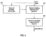
- Fig. 4 illustrates an inventive apparatus for performing parameter analysis for time segments having variable and signal dependant time borders.
- the inventive apparatus includes means 401 for dividing the input signal into one or several time segments.
- the time borders that separate the time segments are provided by means 402.
- Means 402 uses a detector specially designed for extracting spatial cues that is relevant for deciding where to set the time borders.
- Means 401 outputs all the input signal divided into one or several time segments. This output is input to means 403 for separate parameter analysis for each time segment.
- Means 403 outputs one parameter set per time segment being analysed.
- Fig. 5 illustrates an example of how the time grid generator can perform for a hypothetical input signal.
- one parameter set per data frame is used if no other time border information is present.
- the in Fig. 5 depicted time borders are the output from means 402 in Fig. 4 .
- the in Fig. 5 depicted time segments are provided by means 401 in Fig. 4 .
- the apparatus for encoding a stereo signal to obtain a mono output signal and the stereo parameter set includes the means for calculating the mono signal by combining a left and a right channel of the stereo signals by weighted addition. Additionally, a means 403 are generating a first stereo parameter set using a portion of the left channel and a portion of the right channel, the portions starting at a first time border is connected to the means for determining the validity of the first stereo parameter set for subsequent portions of the left channel and the right channel.
- the means for determining is collectively formed by the means 402 and 401 in Fig. 1 .
- the means for determining is operative to generate a second time border and to activate the means for generating, when it is determined that this first stereo parameter set is not valid anymore so that a second stereo parameter set for portions of the left and right channels starting at the second time border is generated.
- Fig. 4 Not shown in Fig. 4 are means for outputting the mono signal, the first stereo parameter set and the first time border associated with the first stereo parameter set and the second stereo parameter set and the second time border associated with the second stereo parameter set as the parametrically encoded stereo signal.
- the means for determining a validity of a stereo parameter set can include a transient detector, since the probability is high that, after a transient, a new stereo parameter has to be generated, since a signal has changed its shape significantly.
- the means for determining a validity can include an analysis-by-synthesis device, which is adapted for decoding the mono signal and the stereo parameter set to obtain a decoded left and a decoded right channel, to compare the decoded left channel and the decoded right channel to the left channel and to the right channel, and to activate the means for generating, when the decoded left channel and the decoded right channel are different from the left channel and the right channel by more than the predetermined threshold.
- an analysis-by-synthesis device which is adapted for decoding the mono signal and the stereo parameter set to obtain a decoded left and a decoded right channel, to compare the decoded left channel and the decoded right channel to the left channel and to the right channel, and to activate the means for generating, when the decoded left channel and the decoded right channel are different from the left channel and the right channel by more than the predetermined threshold.
- Data frame 1 The time segment corresponding to parameter set 1 starts at the beginning of data frame 1 since no other time border information is present in this data frame.
- Data frame 2 Two time borders are present in this data frame.
- the time segment corresponding to parameter set 2 starts at the first time border in this data frame.
- the time segment corresponding to parameter set 3 starts at the second time border in this data frame.
- Data frame 3 One time border is present in this data frame.
- the time segment corresponding to parameter set 4 starts at the time border in this data frame.
- Data frame 4 One time border is present in this data frame. This time border coincides with the start border of the data frame 4 and does not have to be signalled since this is handled by the default case. Hence, this time border signal can be removed. The time segment corresponding to parameter set 5 starts at the beginning of data frame 4, even without signalling this time border.
- the filter in question should preferably be of all-pass character.
- One successful approach is to use similar all-pass filters used for artificial reverberation processes.
- Artificial reverberation algorithms usually requires high time resolution to give an impulse response that is satisfactory diffuse in time.
- the filterbank provides excellent possibilities to let the reverberation properties be frequency selective in terms of for example reverberation equalisation, decay time, density and timbre.
- the filter bank implementations usually exchanges time resolution for higher frequency resolution which normally makes it hard to implement a reverberation process that is smooth enough in time.
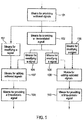
- Fig. 1 illustrates an inventive apparatus for the de-correlation method of signals as used in a parametric stereo system.
- the inventive apparatus includes means 101 for providing a plurality of subband signals.
- the providing means can be a complex QMF filterbank, where every signal is associated with a subband index.
- the subband signals output by the means 101 from Fig 1 . are input into a means 102 for providing a de-correlated signal 102, and into a means 103 and 106 for modifying the subband signal.
- the output from 102 is input into a means 104 and 105 for modifying the of the signal, and the output of 103, 104, 105 and 106 are input into a means for adding, 107 and 108, the subband signals.
- the means for modifying 103,104, 105 and 106, the subband signals adjusts the level of the de-correlated signal and the un-processed signal being the output of 101, by multiplying the subband signal with a gain factor, so that every sum of every pair results in a signal with the amount of de-correlated signal given by the control parameters.
- the gain factors used in the means for modifying, 103 - 106 are not limited to a positive value. It can also be a negative value.
- the output from the means for adding subband signals 107 and 108 is input to the means for providing a time-domain signal 109 and 110.
- the output from 109 corresponds to the left channel of the re-constructed stereo signal
- the output from 110 corresponds to the right channel of the re-constructed stereo signal.
- the same de-correlator is used for both output channels, while the means for adding the de-correlated signal with the un-processed signal are separate for the two output channels.
- the presently described embodiment thereby ensures that the two output signals can be identical as well as completely de-correlated, dependent on the control data provided to the means for adjusting the levels of the signals, and the control data provided to the means for adding the signals.
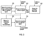
- Fig. 2 a block diagram of the means for providing a de-correlated signal is displayed.
- the input subband signal is input to the means for filtering a subband signal 201.
- the filtering step is a reverberation unit incorporating all-pass filtering.
- the filter coefficients used are given by the means for providing filter coefficients 202.
- the subband index of the currently processed subband signal is input to 202. In one embodiment of the present invention different filter coefficients are calculated based on the subband index provided to 202.
- the filtering step in 201 relies on delayed samples of the input subband signal as well as delayed samples of intermediate signals in the filtering procedure.
- means for providing integer subband sample delay and fractional subband sample delay are provided by 203.
- the output of 201 is input to a means for adjusting the level of the subband signal 204, and also to a means for estimating signal characteristics of the subband signal 205.
- the characteristics estimated is the transient behaviour of the subband signal.
- a detected transient is signalled to the means for adjusting the level of a subband signal 204, so that the level of the signal is reduced during transient passages.
- the output from 204 is the de-correlated signal input to 104 and 105 of Fig. 1 .
- Fig. 3 the single analysis filterbank and the two synthesis filterbanks are shown.
- the analysis filterbank 301 operates on the mono input signal, while the synthesis filterbanks 302 and 303 operate on the re-constructed stereo signals.
- Fig. 1 shows the inventive apparatus for generating a decorrelation signal which is indicated by reference 102.
- this apparatus includes means for providing a plurality of subband signals, wherein a subband signal includes the sequence of at least two subband samples, the sequence of the subband samples representing a bandwidth of the subband signal which is smaller than a bandwidth of the input signal.
- Each subband signal is input into the means 201 for filtering.
- Each means 201 for filtering includes a reverberation filter so that a plurality of reverberated subband signals are obtained, wherein the plurality of reverberated subband signals together represent the decorrelation signal.
- there can be a subband-wise postprocessing of reverberated subband signals which is performed by block 204, which is controlled by block 205.
- Each reverberation filter is set to a certain delay, and preferably a fractional delay, and each reverberation filter has several filter coefficients, which, as it is shown in Fig. 2 , depend on the subband index. This means that it is preferred to use the same delay for each subband but to use different sets of filter coefficients for the different subbands. This is symbolized by means 203 and 202 in Fig. 2 , although it is to be mentioned here that delays and filter coefficients are preferably fixedly determined when shipping a decorrelation device, wherein the delays and filter coefficients may be determined empirically using listening tests etc.
- a multi-channel decoder is shown by Fig. 1 and includes the inventive apparatus for generating the correlation signal, which is termed 102 in Fig. 1 .
- the multi-channel decoder shown in Fig. 1 is for decoding a mono signal and an associated inter-channel coherence measure, the inter-channel coherence measure representing a coherence between a plurality of original channels, wherein the mono signal is derived from the plurality of original channels.
- Block 102 in Fig. 1 constitutes a generator for generating a decorrelation signal for the mono signal.
- Blocks 103, 104, 105, 106 and 107 and 108 constitute a mixer for mixing the mono signal and the decorrelation signal in accordance with the first mixing mode to obtain a first decoded output signal and in accordance with the second mixing mode to obtain a second decoded output signal, wherein the mixer is operative to determine the first mixing mode and the second mixing mode based on the inter-channel coherence measure transmitted as a side information to the mono signal.
- the mixer is preferably operative to mix in a subband domain based on separate inter-channel coherence measures for different subbands.
- the multi-channel decoder further comprises means 109 and 110 for converting the first and second decoded output signals from the subband domain in a time domain to obtain a first decoded output signal and a second decoded output signal in the time domain. Therefore, the inventive means 102 for generating a decorrelation signal and the inventive multi-channel decoder as shown in Fig. 1 operate in the subband domain and perform, as the very last step, a subband domain to time domain conversion.
- the inventive device can be implemented in hardware or in software or in a firmware including hardware constituents and software constituents.
- the invention also is a computer program having a computer-readable code for carrying out the inventive methods when running on a computer.
- An embodiment comprises an apparatus 102 for generating a decorrelation signal using an input signal means 101 for providing a plurality of subband signals, wherein a subband signal includes a sequence of at least two subband samples, the sequence of the subband samples representing a bandwidth of the subband signal, which is smaller than a bandwidth of the input signal; and means 201 may filter each subband signal using a reverberation filter to obtain a plurality of reverberated subband signals, wherein a plurality of reverberated subband signals together represent the decorrelation signal.
- the means 201 for filtering may be operative to apply a delay to the subband signal.
- the means 201 for filtering is operative to apply a fractional delay to a subband signal, the fractional delay may be greater than "0" and smaller than a sampling period of the subband signal.
- the fractional delay is smaller than 0.9 of the sampling period of the subband signal and greater than 0.1 of the sampling period of the subband signal.
- the means 201 for filtering is adapted to have an all-pass characteristic.
- the apparatus for generating a decorrelation signal using an input signal in which the reverberation filter 201 may be operative to apply the same delay to each subband signal.
- the reverberation filter 201 is adapted to have different sets or filter coefficients for each subband signal.
- the reverberation filter is operative to introduce predetermined phase delays into the subband signals.
- the number of subbands is smaller than or equal to 128 and larger than 1.
- the input signal may include a block of a predetermined number of input samples, and in which the number of subband signals may be smaller than the number of input samples.
- the number of subband samples is multiplied by the number of subbands results in the predetermined number of input samples.
- the means 101 for providing may be a complex quadrature-mirror-filterbank.
- An embodiment comprises the multi-channel decoder for decoding a mono signal and an associated inter-channel coherence measure, the inter-channel coherence measure representing a coherence between a plurality of original channels, the mono signal may be derived from the plurality of original channels, comprising a generator 102 for generating a decorrelation signal from the mono signal; a mixer 103, 104, 105, 106, 107, 108 for mixing the mono signal and the decorrelation signal in accordance with a first mixing mode to obtain a first decoded output signal and in accordance with a second mixing mode to obtain a second decoded output signal, wherein the mixer is operative to determine the first mixing mode and the second mixing mode based on the inter-channel coherence measure.
- the mixer is operative to mix in a subband domain based on separate inter-channel coherence measures for different subbands, and which further comprises means 109, 110 for converting the first and the second decoded output signals from the subband domain in the time domain to obtain time domain first and second decoded output signals.
- the plurality of original channels includes a left stereo channel and a right stereo channel, and in which the first decoded output signal is a decoded left stereo channel, and in which the second decoded output signal may be a decoded right stereo channel.
- the mixer may include means 103, 106 for modifying a subband of the mono signal or means 104 and 105 for modifying the subband of the decorrelation signal.
- the means for modifying may be implemented as signal level modifier devices.
- the mixer may include an adder 107 for adding an unmodified subband of the mono signal and a modified subband of the decorrelation signal or for adding a modified subband of the mono signal and an unmodified subband of the decorrelation signal or for adding a modified subband of the mono signal and a modified subband of the decorrelation signal to obtain a subband of a first decoded output channel or the second decoded output channel.
- the generator 102 includes a filterbank for providing the plurality of subbands of the mono signal, the filterbank having a subband output connected to the mixer and the reverberation filter (201) for the subband.
- An embodiment comprises the method of generating a decorrelation signal using an input signal, comprising: providing 101 a plurality of subband signals, wherein a subband signal includes a sequence of at least two subband samples, the sequence of the subband samples representing a bandwidth of the subband signal, which is smaller than a bandwidth of the input signal; and filtering 201 each subband signal using a reverberation filter to obtain a plurality of reverberated subband signals, wherein a plurality of reverberated subband signals together represent the decorrelation signal.
- An embodiment comprises the method of multi-channel decoding for decoding a mono signal and an associated inter-channel coherence measure, the inter-channel coherence measure representing a coherence between a plurality of original channels, the mono signal being derived from the plurality of original channels, comprising: generating 102 a decorrelation signal from the mono signal in accordance with the method of claim 20; mixing 103, 104, 105, 106, 107, 108 the mono signal and the decorrelation signal in accordance with a first mixing mode to obtain a first decoded output signal and in accordance with a second mixing mode to obtain a second decoded output signal, wherein the mixer is operative to determine the first mixing mode and the second mixing mode based on the inter-channel coherence measure.
- An embodiment comprises the apparatus for encoding a stereo signal to obtain a mono output signal and a stereo parameter set, comprising: means for calculating the mono signal by combining a left and a right channel of the stereo signals; means 403 for generating a first stereo parameter set using a portion of the left channel and a portion of the right channel, the portion starting at a first time border; means 401, 402 for determining a validity of the first stereo parameter set for subsequent portions of the left channel and the right channel, wherein the means for determining is operative to generate second time border, and activate the means for generating, when it is determined that the stereo parameter set is not valid anymore so that a second stereo parameter set for portions of the left and right signals starting at the second time border is generated; and means for outputting the mono signal and the first stereo parameter set and the first time border associated with the first parameter set, and the second stereo parameter set and the second time border associated with the second stereo parameter set.
- An embodiment comprises the apparatus for encoding, in which the means for generating is operative to calculate, as the stereo parameter set, an inter channel time difference parameter, an inter-channel level difference parameter, and/or an inter-channel coherence parameter.
- An embodiment comprises the apparatus for encoding, in which the means for determining includes the transient detector, which is arranged for activating the means for generating, when a transient is detected, and to generate a time instant of the transient as the second time border.
- the means for determining is an analysis-by-synthesis device, which is adapted for decoding the mono signal and the stereo parameter set to obtain a decoded left channel and a decoded right channel; comparing the decoded left channel and the decoded right channel to the left channel and the right channel; and activating the means for generating, when the decoded left channel and the decoded right channel are different from the left channel and the right channel by more than a predetermined threshold.
- An embodiment comprises the method of encoding a stereo signal to obtain a mono output signal and a stereo parameter set, comprising: calculating the mono signal by combining a left and a right channel of the stereo signals; generating 403 a first stereo parameter set using a portion of the left channel and a portion of the right channel, the portion starting at a first time border; determining 401, 402 a validity of the first stereo parameter set for subsequent portions of the left channel and the right channel, by generating a second time border, and conducting the step of generating, when it is determined that the stereo parameter set is not valid anymore so that a second stereo parameter set for portions of the left and right signals starting at the second time border is generated; and outputting the mono signal and the first stereo parameter set and the first time border associated with the first parameter set, and the second stereo parameter set and the second time border associated with the second stereo parameter set.
- An embodiment comprises a computer program having a computer-readable code for carrying out, when running on a computer, the method of generating, the method of multi-channel decoding or the method of encoding.
- EEEs enumerated example embodiments
Abstract
Description
- The present invention relates to audio source coding systems but the same methods could also be applied in many other technical fields. Different techniques that are useful for audio coding systems using parametric representations of stereo properties are introduced.
- The present invention relates to parametric coding of the stereo image of an audio signal. Typical parameters used for describing stereo image properties are inter-channel intensity difference (IID), inter-channel time difference (ITD), and inter-channel coherence (IC). In order to re-construct the stereo image based on these parameters, a method is required that can re-construct the correct level of correlation between the two channels, according to the IC parameter. This is accomplished by a de-correlation method.
- There are a couple of methods available for creation of decorrelated signals. Ideally, a linear time invariant (LTI) function with all-pass frequency response is desired. One obvious method for achieving this is by using a constant delay. However, using a delay, or any other LTI all-pass functions, will result in non-all-pass response after adding the non-processed signal. In the case of a delay, the result will be a typical comb-filter. The comb-filter often gives an undesirable "metallic" sound that, even if the stereo widening effect can be efficient, reduces much naturalness of the original.
- Frequency domain methods for generating a de-correlated signal by adding a random sequence to the IID values along the frequency axis, where different sequences are used for the different audio channels, are also known from prior art. One problem with frequency domain decorrelation by the random sequence modifications is the introduction of pre-echoes. Subjective tests have shown that for non-stationary signals, pre-echoes are by far more annoying than post-echoes, which is also well supported by established psycho acoustical principles. This problem could be reduced by dynamically adapting transform sizes to the signal characteristics in terms of transient content. However, switching transform sizes is always a hard (i.e., binary) decision that affects the full signal bandwidth and that can be difficult to accomplish in a robust manner.
- United States patent application publication
US 2003/0219130 A1 discloses a coherence-based audio coding and synthesis. In particular, an auditory scene is synthesized from a mono audio signal by modifying, for each critical band, an auditory scene parameter such as an inter-aural level difference (ILD) and/or an inter-aural time difference (ITD) for each subband within the critical band, where the modification is based on an average estimated coherence for the critical band. The coherence-based modification produces auditory scenes having object widths, which more accurately match the widths of the objects in the original input auditory scene. Stereo parameters are the well-known BCC parameters, wherein BCC stands for binaural cue coding. When generating two different decorrelated output channels, frequency coefficients as obtained by a discrete Fourier transform are grouped together in a single critical band. Based on the inter-channel coherence measure, weighting factors are multiplied by a pseudo-random sequence which is preferably chosen such that the variance is approximately constant for all critical bands, and the average is "0" within each critical band. The same sequence is applied to the spectral coefficients of each different frame. - It is the object of the present invention to provide a decoding concept for parametrically encoded multi-channel signals or an encoding concept for generating such signals which result in a good audio quality and a good coding efficiency.
- This object is achieved by an apparatus for generating a decorrelation signal in accordance with
claim 1, a multi-channel decoder in accordance with claim 12, a method of generating a decorrelation signal in accordance with claim 19, a method of multi-channel decoding in accordance with claim 20, an apparatus for encoding a stereo signal in accordance with claim 21 or a method of encoding a stereo signal in accordance with claim 25 a decoder in accordance with claim 26, a method of decoding in accordance with claim 27, or a computer program in accordance with claim 28. - The present invention is based on the finding that, on the decoding side, a good decorrelation signal for generating a first and a second channel of a multi-channel signal based on the input mono signal is obtained, when a reverberation filter is used, which introduces an integer or preferably a fractional delay into the input signal. Importantly, this reverberation filter is not applied to the whole input signal. Instead, several reverberation filters are applied to several subbands of the original input signal, i.e., the mono signal so that the reverberation filtering using the reverberation filters is not applied in a time domain or in the frequency domain, i.e., in the domain which is reached, when a Fourier transform is applied. Inventively, the reverberation filtering using reverberation filters for the subbands is individually performed in the subband domain.
- A subband signal includes a sequence of at least two subband samples, the sequence of the subband samples representing a bandwidth of the subband signal, which is smaller than the bandwidth of the input signal. Naturally, the frequency bandwidth of a subband signal is higher than a frequency bandwidth attributed to a frequency coefficient obtained by Fourier transform. The subband signals are preferably generated by means of a filterbank having for example 32 or 64 filterbank channels, while an FFT would have, for the same example, 1.024 or 2.048 frequency coefficients, i.e., frequency channels.
- The subband signals can be subband signals obtained by subband-filtering a block of samples of the input signal. Alternatively, the subband filterbank can also be applied continuously without a block wise processing. For the present invention, however, block wise processing is preferred.
- Since the reverberation filtering is not applied to the whole signal, but is applied subband-wise, a "metallic" sound caused by comb-filtering is avoided.
- In cases, in which a sample period between two subsequent subband samples of the subband is too large for a good sound impression at the decoder end, it is preferred to use fractional delays in a reverberation filter such as a delay between 0.1 and 0.9 and preferably 0.2 to 0.8 of the sampling period of the subband signal. It is noted that in case of critical sampling, and when 64 subband signals are generated using a filterbank having 64 filterbank channels, the sampling period in a subband signal is 64 times larger than the sampling period of the original input signal.
- It is to be noted here that the delays are an integral part of the filtering process used in the reverberation device. The output signal constitutes of a multitude of delayed versions of the input signal. It is preferred to delay signals by fractions of the subband sampling period, in order to achieve a good reverberation device in the subband domain.
- In preferred embodiments of the present invention, the delay, and preferably the fractional delay introduced by each reverberation filter in each subband is equal for all subbands. Nevertheless, the filter coefficients are different for each subbands. It is preferred to use IIR filters. Depending on the actual situation, fractional delay and the filter coefficients for the different filters can be determined empirically using listening tests.
- The subbands filtered by the set of reverberation filters constitute a decorrelation signal which is to be mixed with the original input signal, i.e., the mono signal to obtain a decoded left channel and decoded right channel. This mixing of a decorrelation signal with the original signal is performed based on an inter-channel coherence parameter transmitted together with the parametrically encoded signal. To obtain different left and right channels, i.e., different first and second channels, mixing of the decorrelation signal with a mono signal to obtain the first output channel is different from mixing the decorrelation signal with the mono signal to obtain the second output channel.
- To obtain higher efficiency on the encoding side, multi-channel encoding is performed using an adaptive determination of the stereo parameter set. To this end, an encoder includes, in addition to a means for calculating the mono signal and in addition to a means for generating a stereo parameter set, a means for determining a validity of stereo parameter sets for subsequent portions of the left an right channels. Preferably, the means for determining is operative to activate the means for generating, when it is determined that the stereo parameter set is not valid anymore so that a second stereo parameter set is calculated for portions of the left and right channels starting at a second time border. This second time border is also determined by the means for determining a validity.
- The encoded output signal then includes the mono signal, a first stereo parameter set and a first time border associated with the first parameter set and the second stereo parameter set and the second time border associated with the second stereo parameter set. On the decoding side, the decoder will use a valid stereo parameter set until a new time border is reached. When this new time border is reached, the decoding operations are performed using the new stereo parameter set.
- Compared to prior art methods, which did a block wise processing and, therefore, a block wise determination of stereo parameter sets, the inventive adaptive determination of stereo parameter sets for different encoder-side determined time borders provides a high coding efficiency on the one hand end and a high coding quality on the other hand. This is due to the fact that for relatively stationary signals, the same stereo parameter set can be used for many blocks of the samples of the mono signal without introducing audible errors. On the other hand, when non-stationary signals are concerned, the inventive adaptive stereo parameter determination provides an improved time resolution so that each signal portion has its optimum stereo parameter set.
- The present invention provides a solution to the prior art problems by using a reverberation unit as a de-correlator implemented with fractional delay lines in a filterbank, and using adaptive level adjustment of the de-correlated reverberated signal.
- Subsequently, several aspects of the present invention are outlined.
- One aspect of the invention is a method for delaying a signal by: filtering a real-valued time domain signal through the analysis part of complex filterbank; modifying the complex-valued subband signals obtained from the filtering; and filtering the modified complex-valued subband signals through the synthesis part of the filterbank; and taking the real part of the complex-valued time domain output signal, where the output signal is the sum of the signals obtained from the synthesis filtering.
- Another aspect of the invention is a method for modifying the complex valued subband signals by filtering each complex-valued subband signal with a complex valued finite impulse response filter where the finite impulse response filter for subband number n is given by a discrete time Fourier transform of the form

- Another aspect of the invention is a method for modifying the complex valued subband signals by filtering where the filter Gτ (ω) approximately satisfies Vτ (ω)Gτ (ω)+Vτ (ω+π)Gτ (ω+π)=1, where Vτ(ω) is the discrete time Fourier transform of the sequence

- Another aspect of the invention is a method for modifying the complex valued subband signals by filtering where the filter Gτ (ω) satisfies Gτ (-ω)=Gτ (ω+π)* such that even indexed impulse response samples are real valued and odd indexed impulse response samples are purely imaginary valued.
- Another aspect of the invention is a method for coding of stereo properties of an input signal, by at an encoder, calculate time grid parameters describing the location in time for each stereo parameter set, where the number of stereo parameter sets are arbitrary, and at a decoder, applying parametric stereo synthesis according to that time grid.
- Another aspect of the invention is a method for coding of stereo properties of an input signal, where the time localisation for the first stereo parameter set is, in the case of where a time cue for the stereo parameter set coincides with the beginning of a frame, signalled explicitly instead of signalling the time pointer.
- Another aspect of the invention is a method for generation of stereo decorrelation for parametric stereo reconstruction, by at a decoder, applying an artificial reverberation process to synthesise the side signal.
- Another aspect of the invention is a method for generation of stereo decorrelation for parametric stereo reconstruction by, at the decoder, the reverberation process is made within a complex modulated filterbank using phase delay adjustment in each filter bank channel.
- Another aspect of the invention is a method for generation of stereo decorrelation for parametric stereo reconstruction by, at the decoder, the reverberation process utilises a detector designed for finding signals where the reverberation tail could be unwanted and let the reverberation tail be attenuated or removed.
- The present invention will now be described by way of illustrative examples, not limiting the scope or spirit of the invention, with reference to the accompanying drawings, in which:
- Fig. 1
- illustrates a block diagram of the inventive apparatus;
- Fig. 2
- illustrates a block diagram of the means for generating a de-correlated signal;
- Fig. 3
- illustrates the analysis of a single channel and the synthesis of the stereo channel pair based on the reconstructed stereo subband-signals according to the present invention;
- Fig. 4
- illustrates a block diagram of the division of the parametric stereo parameters sets into time segments, based on the signal characteristic; and
- Fig. 5
- illustrates an example of the division of the parametric stereo parameters sets into time segments, based on the signal characteristic.
- The below-described embodiments are merely illustrative for the principles of the present invention for parametric stereo coding. It is understood that modifications and variations of the arrangements and the details described herein will be apparent to others skilled in the art. It is the intent, therefore, to be limited only by the scope of the impending patent claims and not by the specific details presented by way of description and explanation of the embodiments herein.
- Delaying a signal by a fraction of a sample can be achieved by several prior art interpolation methods. However, special cases arises when the original signal is available as oversampled complex valued samples. Performing fractional delay in the qmf bank by only applying phase delay by a factor for, each qmf channel corresponding to a constant time delay, results in severe artefacts.
- This can efficiently be avoided by using a compensation filter according to a novel approach allowing high quality approximations to arbitrary delays in any complex-exponential-modulated filterbank. A detailed description follows below.
- For ease of computations a complex exponential modulated L-band filterbank will be modelled here by a continuous time windowed transform using the synthesis waveforms

spacing 1/L. It is assumed that the real valued window v(t) is chosen such that for real valued signals x(t) it holds to very high precision that


- In order to achieve a delay of size τ, such that y(t)=x(t-τ), the problem is to design filters Hn (ω) for n≥0 such that


- In the case of a discrete time L-band filter bank with prototype filter p(k), the obtained delay in sample units is Lτ and the computation (12) is replaced by

- Parametric stereo systems always leads to compromises in terms of limited time or frequency resolution in order to minimise conveyed data. It is however well known from psycho-acoustics that some spatial cues can be more important than others, which leads to the possibility to discard the less important cues. Hence, the time resolution does not have to be constant. Great gain in bitrate could be achieved by letting the time grid synchronise with the spatial cues. It can easily be done by sending a variable number of parameter sets for each data frame that corresponds to a time segment of fixed size. In order to synchronise the parameter sets with corresponding spatial cues, additional time grid data describing the location in time for each parameter set has to be sent. The resolution of those time pointers could be chosen to be quite low to keep the total amount of data minimised. A special case where a time cue for a parameter set coincides with the beginning of a frame could be signalled explicitly to avoid sending that time pointer.
-
Fig. 4 illustrates an inventive apparatus for performing parameter analysis for time segments having variable and signal dependant time borders. The inventive apparatus includes means 401 for dividing the input signal into one or several time segments. The time borders that separate the time segments are provided bymeans 402.Means 402 uses a detector specially designed for extracting spatial cues that is relevant for deciding where to set the time borders.Means 401 outputs all the input signal divided into one or several time segments. This output is input to means 403 for separate parameter analysis for each time segment.Means 403 outputs one parameter set per time segment being analysed. -
Fig. 5 illustrates an example of how the time grid generator can perform for a hypothetical input signal. In this example one parameter set per data frame is used if no other time border information is present. Hence, when no other time border information is present, the inherent time borders of the data frame is used. The inFig. 5 depicted time borders are the output from means 402 inFig. 4 . The inFig. 5 depicted time segments are provided bymeans 401 inFig. 4 . - The apparatus for encoding a stereo signal to obtain a mono output signal and the stereo parameter set includes the means for calculating the mono signal by combining a left and a right channel of the stereo signals by weighted addition. Additionally, a
means 403 are generating a first stereo parameter set using a portion of the left channel and a portion of the right channel, the portions starting at a first time border is connected to the means for determining the validity of the first stereo parameter set for subsequent portions of the left channel and the right channel. - The means for determining is collectively formed by the
means Fig. 1 . - Particularly, the means for determining is operative to generate a second time border and to activate the means for generating, when it is determined that this first stereo parameter set is not valid anymore so that a second stereo parameter set for portions of the left and right channels starting at the second time border is generated.
- Not shown in
Fig. 4 are means for outputting the mono signal, the first stereo parameter set and the first time border associated with the first stereo parameter set and the second stereo parameter set and the second time border associated with the second stereo parameter set as the parametrically encoded stereo signal. The means for determining a validity of a stereo parameter set can include a transient detector, since the probability is high that, after a transient, a new stereo parameter has to be generated, since a signal has changed its shape significantly. Alternatively, the means for determining a validity can include an analysis-by-synthesis device, which is adapted for decoding the mono signal and the stereo parameter set to obtain a decoded left and a decoded right channel, to compare the decoded left channel and the decoded right channel to the left channel and to the right channel, and to activate the means for generating, when the decoded left channel and the decoded right channel are different from the left channel and the right channel by more than the predetermined threshold. - Data frame 1: The time segment corresponding to parameter set 1 starts at the beginning of
data frame 1 since no other time border information is present in this data frame. - Data frame 2: Two time borders are present in this data frame. The time segment corresponding to parameter set 2 starts at the first time border in this data frame. The time segment corresponding to parameter set 3 starts at the second time border in this data frame.
- Data frame 3: One time border is present in this data frame. The time segment corresponding to parameter set 4 starts at the time border in this data frame.
- Data frame 4: One time border is present in this data frame. This time border coincides with the start border of the data frame 4 and does not have to be signalled since this is handled by the default case. Hence, this time border signal can be removed. The time segment corresponding to parameter set 5 starts at the beginning of data frame 4, even without signalling this time border.
- One vital part of making the stereo synthesis in a parametric stereo system is to decrease the coherence between the left and right channel in order to create wideness of the stereo image. It can be done by adding a filtered version of the original mono signal to the side signal, where the side and mono signal is defined by:


- In order to not change the timbre too much, the filter in question should preferably be of all-pass character. One successful approach is to use similar all-pass filters used for artificial reverberation processes. Artificial reverberation algorithms usually requires high time resolution to give an impulse response that is satisfactory diffuse in time. There are great advantages in basing an artificial reverberation algorithm on a complex filter bank such as the complex qmf bank. The filterbank provides excellent possibilities to let the reverberation properties be frequency selective in terms of for example reverberation equalisation, decay time, density and timbre. However, the filter bank implementations usually exchanges time resolution for higher frequency resolution which normally makes it hard to implement a reverberation process that is smooth enough in time. To deal with this problem a novel method would be to use a fractional delay approximation by only applying phase delay by a factor for, each qmf channel corresponding to a constant time delay. This primitive fractional delay method introduces severe time smearing that fortunately is very much desired in this case. The time smearing contributes to the time diffusion which is highly desirable for reverberation algorithms and gets bigger as the phase delay approaches pi/2 or - pi/2.
- Artificial reverberation processes are for natural reasons processes with an infinite impulse response, and offers natural exponential decays. In [
PCT/SE02/01372 -
Fig. 1 illustrates an inventive apparatus for the de-correlation method of signals as used in a parametric stereo system. The inventive apparatus includes means 101 for providing a plurality of subband signals. The providing means can be a complex QMF filterbank, where every signal is associated with a subband index. - The subband signals output by the
means 101 fromFig 1 . are input into ameans 102 for providing ade-correlated signal 102, and into ameans means - In the presently described embodiment of the invention, the means for modifying 103,104, 105 and 106, the subband signals, adjusts the level of the de-correlated signal and the un-processed signal being the output of 101, by multiplying the subband signal with a gain factor, so that every sum of every pair results in a signal with the amount of de-correlated signal given by the control parameters. It should be noted that the gain factors used in the means for modifying, 103 - 106, are not limited to a positive value. It can also be a negative value.
- The output from the means for adding subband signals 107 and 108, is input to the means for providing a time-
domain signal - In
Fig. 2 a block diagram of the means for providing a de-correlated signal is displayed. The input subband signal is input to the means for filtering asubband signal 201. In the presently described embodiment of the present invention the filtering step is a reverberation unit incorporating all-pass filtering. The filter coefficients used are given by the means for providingfilter coefficients 202. The subband index of the currently processed subband signal is input to 202. In one embodiment of the present invention different filter coefficients are calculated based on the subband index provided to 202. The filtering step in 201, relies on delayed samples of the input subband signal as well as delayed samples of intermediate signals in the filtering procedure. - It is an essential feature of the present invention that means for providing integer subband sample delay and fractional subband sample delay are provided by 203. The output of 201 is input to a means for adjusting the level of the
subband signal 204, and also to a means for estimating signal characteristics of thesubband signal 205. In a preferred embodiment of the present invention the characteristics estimated is the transient behaviour of the subband signal. In this embodiment a detected transient is signalled to the means for adjusting the level of asubband signal 204, so that the level of the signal is reduced during transient passages. The output from 204 is the de-correlated signal input to 104 and 105 ofFig. 1 . - In
Fig. 3 the single analysis filterbank and the two synthesis filterbanks are shown. Theanalysis filterbank 301, operates on the mono input signal, while thesynthesis filterbanks -
Fig. 1 , therefore, shows the inventive apparatus for generating a decorrelation signal which is indicated byreference 102. As it is shown inFig. 1 or3 , this apparatus includes means for providing a plurality of subband signals, wherein a subband signal includes the sequence of at least two subband samples, the sequence of the subband samples representing a bandwidth of the subband signal which is smaller than a bandwidth of the input signal. Each subband signal is input into themeans 201 for filtering. Each means 201 for filtering includes a reverberation filter so that a plurality of reverberated subband signals are obtained, wherein the plurality of reverberated subband signals together represent the decorrelation signal. Preferably, as it is shown inFig. 2 , there can be a subband-wise postprocessing of reverberated subband signals which is performed byblock 204, which is controlled byblock 205. - Each reverberation filter is set to a certain delay, and preferably a fractional delay, and each reverberation filter has several filter coefficients, which, as it is shown in
Fig. 2 , depend on the subband index. This means that it is preferred to use the same delay for each subband but to use different sets of filter coefficients for the different subbands. This is symbolized bymeans Fig. 2 , although it is to be mentioned here that delays and filter coefficients are preferably fixedly determined when shipping a decorrelation device, wherein the delays and filter coefficients may be determined empirically using listening tests etc. - A multi-channel decoder is shown by
Fig. 1 and includes the inventive apparatus for generating the correlation signal, which is termed 102 inFig. 1 . The multi-channel decoder shown inFig. 1 is for decoding a mono signal and an associated inter-channel coherence measure, the inter-channel coherence measure representing a coherence between a plurality of original channels, wherein the mono signal is derived from the plurality of original channels.Block 102 inFig. 1 constitutes a generator for generating a decorrelation signal for the mono signal.Blocks - The mixer is preferably operative to mix in a subband domain based on separate inter-channel coherence measures for different subbands. In this case, the multi-channel decoder further comprises
means Fig. 1 operate in the subband domain and perform, as the very last step, a subband domain to time domain conversion. - Depending on the actual situation, the inventive device can be implemented in hardware or in software or in a firmware including hardware constituents and software constituents. When implemented in software partially or fully, the invention also is a computer program having a computer-readable code for carrying out the inventive methods when running on a computer.
- An embodiment comprises an
apparatus 102 for generating a decorrelation signal using an input signal means 101 for providing a plurality of subband signals, wherein a subband signal includes a sequence of at least two subband samples, the sequence of the subband samples representing a bandwidth of the subband signal, which is smaller than a bandwidth of the input signal; and means 201 may filter each subband signal using a reverberation filter to obtain a plurality of reverberated subband signals, wherein a plurality of reverberated subband signals together represent the decorrelation signal. - In a further embodiment of the apparatus for generating a decorrelation signal using an input signal, the
means 201 for filtering may be operative to apply a delay to the subband signal. - In a further embodiment of the apparatus for generating a decorrelation signal using an input signal, the
means 201 for filtering is operative to apply a fractional delay to a subband signal, the fractional delay may be greater than "0" and smaller than a sampling period of the subband signal. - In a further embodiment of the apparatus for generating a decorrelation signal using an input signal, the fractional delay is smaller than 0.9 of the sampling period of the subband signal and greater than 0.1 of the sampling period of the subband signal.
- In a further embodiment of the apparatus for generating a decorrelation signal using an input signal, the
means 201 for filtering is adapted to have an all-pass characteristic. - In a further embodiment of the apparatus for generating a decorrelation signal using an input signal in which the
reverberation filter 201 may be operative to apply the same delay to each subband signal. - In a further embodiment of the apparatus for generating a decorrelation signal using an input signal, the
reverberation filter 201 is adapted to have different sets or filter coefficients for each subband signal. - In a further embodiment of the apparatus for generating a decorrelation signal using an input signal, the reverberation filter is operative to introduce predetermined phase delays into the subband signals.
- In a further embodiment of the apparatus for generating a decorrelation signal using an input signal, the number of subbands is smaller than or equal to 128 and larger than 1.
- In a further embodiment of the apparatus for generating a decorrelation signal using an input signal, the input signal may include a block of a predetermined number of input samples, and in which the number of subband signals may be smaller than the number of input samples.
- In a further embodiment of the apparatus for generating a decorrelation signal using an input signal, the number of subband samples is multiplied by the number of subbands results in the predetermined number of input samples.
- In a further embodiment of the apparatus for generating a decorrelation signal using an input signal in which the
means 101 for providing may be a complex quadrature-mirror-filterbank. - An embodiment comprises the multi-channel decoder for decoding a mono signal and an associated inter-channel coherence measure, the inter-channel coherence measure representing a coherence between a plurality of original channels, the mono signal may be derived from the plurality of original channels, comprising a
generator 102 for generating a decorrelation signal from the mono signal; amixer - In a further embodiment of the multi-channel decoder, the mixer is operative to mix in a subband domain based on separate inter-channel coherence measures for different subbands, and which further comprises
means - In a further embodiment of the multi-channel decoder, the plurality of original channels includes a left stereo channel and a right stereo channel, and in which the first decoded output signal is a decoded left stereo channel, and in which the second decoded output signal may be a decoded right stereo channel.
- In a further embodiment of the multi-channel decoder, the mixer may include means 103, 106 for modifying a subband of the mono signal or means 104 and 105 for modifying the subband of the decorrelation signal.
- In a further embodiment of the multi-channel decoder, the means for modifying may be implemented as signal level modifier devices.
- In a further embodiment of the multi-channel decoder, the mixer may include an
adder 107 for adding an unmodified subband of the mono signal and a modified subband of the decorrelation signal or for adding a modified subband of the mono signal and an unmodified subband of the decorrelation signal or for adding a modified subband of the mono signal and a modified subband of the decorrelation signal to obtain a subband of a first decoded output channel or the second decoded output channel. - In a further embodiment of the multi-channel decoder, the
generator 102 includes a filterbank for providing the plurality of subbands of the mono signal, the filterbank having a subband output connected to the mixer and the reverberation filter (201) for the subband. - An embodiment comprises the method of generating a decorrelation signal using an input signal, comprising: providing 101 a plurality of subband signals, wherein a subband signal includes a sequence of at least two subband samples, the sequence of the subband samples representing a bandwidth of the subband signal, which is smaller than a bandwidth of the input signal; and filtering 201 each subband signal using a reverberation filter to obtain a plurality of reverberated subband signals, wherein a plurality of reverberated subband signals together represent the decorrelation signal.
- An embodiment comprises the method of multi-channel decoding for decoding a mono signal and an associated inter-channel coherence measure, the inter-channel coherence measure representing a coherence between a plurality of original channels, the mono signal being derived from the plurality of original channels, comprising: generating 102 a decorrelation signal from the mono signal in accordance with the method of claim 20; mixing 103, 104, 105, 106, 107, 108 the mono signal and the decorrelation signal in accordance with a first mixing mode to obtain a first decoded output signal and in accordance with a second mixing mode to obtain a second decoded output signal, wherein the mixer is operative to determine the first mixing mode and the second mixing mode based on the inter-channel coherence measure.
- An embodiment comprises the apparatus for encoding a stereo signal to obtain a mono output signal and a stereo parameter set, comprising: means for calculating the mono signal by combining a left and a right channel of the stereo signals; means 403 for generating a first stereo parameter set using a portion of the left channel and a portion of the right channel, the portion starting at a first time border; means 401, 402 for determining a validity of the first stereo parameter set for subsequent portions of the left channel and the right channel, wherein the means for determining is operative to generate second time border, and activate the means for generating, when it is determined that the stereo parameter set is not valid anymore so that a second stereo parameter set for portions of the left and right signals starting at the second time border is generated; and means for outputting the mono signal and the first stereo parameter set and the first time border associated with the first parameter set, and the second stereo parameter set and the second time border associated with the second stereo parameter set.
- An embodiment comprises the apparatus for encoding, in which the means for generating is operative to calculate, as the stereo parameter set, an inter channel time difference parameter, an inter-channel level difference parameter, and/or an inter-channel coherence parameter.
- An embodiment comprises the apparatus for encoding, in which the means for determining includes the transient detector, which is arranged for activating the means for generating, when a transient is detected, and to generate a time instant of the transient as the second time border.
- In a further embodiment of the apparatus for encoding, the means for determining is an analysis-by-synthesis device, which is adapted for decoding the mono signal and the stereo parameter set to obtain a decoded left channel and a decoded right channel; comparing the decoded left channel and the decoded right channel to the left channel and the right channel; and activating the means for generating, when the decoded left channel and the decoded right channel are different from the left channel and the right channel by more than a predetermined threshold.
- An embodiment comprises the method of encoding a stereo signal to obtain a mono output signal and a stereo parameter set, comprising: calculating the mono signal by combining a left and a right channel of the stereo signals; generating 403 a first stereo parameter set using a portion of the left channel and a portion of the right channel, the portion starting at a first time border; determining 401, 402 a validity of the first stereo parameter set for subsequent portions of the left channel and the right channel, by generating a second time border, and conducting the step of generating, when it is determined that the stereo parameter set is not valid anymore so that a second stereo parameter set for portions of the left and right signals starting at the second time border is generated; and outputting the mono signal and the first stereo parameter set and the first time border associated with the first parameter set, and the second stereo parameter set and the second time border associated with the second stereo parameter set.
- An embodiment comprises a computer program having a computer-readable code for carrying out, when running on a computer, the method of generating, the method of multi-channel decoding or the method of encoding.
- Various aspects of the present invention may be appreciated from the following enumerated example embodiments (EEEs):
- 1. Apparatus for generating a decorrelation signal using an input signal, comprising:
- a subband filterbank for providing a plurality of subband signals, wherein a subband signal includes a sequence of at least two subband samples, the sequence of the subband samples representing a bandwidth of the subband signal, which is smaller than a bandwidth of the input signal; and
- a reverberation filter to obtain a plurality of reverberated subband signals from the plurality of subband signals, the reverberation filter being operative to apply a delay to each subband signal and being adapted to have different sets of filter coefficients for each subband signal,
- wherein the plurality of reverberated subband signals together represent the decorrelation signal.
- 2. The apparatus of
EEE 1 wherein the delay to each subband signal is the same. - 3. The apparatus of
EEE 2, wherein the delay can be a fractional delay. - 4. The apparatus of
EEE 3, where the fractional delay is greater than zero and smaller than a sampling period. - 5. The apparatus of EEE 4, in which the fractional delay is smaller than 0.9 times the sampling period of the subband signal and greater than 0.1 times the sampling period of the subband signal.
- 6. The apparatus of any of the preceding EEEs, in which filtering of the reverberation filter is adapted to have an all-pass characteristic.
- 7. The apparatus in accordance with any of the preceding EEEs, in which the reverberation filter is operative to introduce predetermined phase delays into the subband signals.
- 8. The apparatus in accordance with any of the preceding EEEs, in which the number of subbands is smaller than or equal to 128 and larger than 1.
- 9. The apparatus in accordance with any of the preceding EEEs, in which the input signal includes a block of a predetermined number of input samples, and in which the number of subband signals is smaller than the number of input samples.
- 10. The apparatus in accordance with any of the preceding EEEs, in which the number of subband samples multiplied by the number of subbands results in the predetermined number of input samples.
- 11. Method of generating a decorrelation signal using an input signal, comprising:
- providing (101) a plurality of subband signals, wherein a subband signal includes a sequence of a least two subband samples, the sequence of the subband samples representing a bandwidth of the subband signal, which is smaller than a bandwidth of the input signal; and
- filtering (201) each subband signal using a reverberation filter to obtain a plurality of reverberated subband signals, wherein the reverberation filter is operative to apply a delay to each subband signal and where the reverberation filter is adapted to have different sets of filter coefficients for each subband signal,
- wherein a plurality of reverberated subband signals together represent the decorrelation signal.
- 12. The method of EEE 11 wherein the delay to each subband signal is the same.
- 13. The method of EEE 12, wherein the delay can be a fractional delay.
Claims (8)
- A method for decoding a monaural audio signal, the method comprising:receiving the monaural audio signal, an associated inter-channel coherence measure, an associated inter-channel time difference measure, and an associated inter-channel intensity difference measure, the inter-channel coherence measure representing a coherence between a plurality of original channels, and the monaural audio signal being derived from the plurality of original channels;filtering the monaural audio signal with a complex exponential modulated filterbank to generate a plurality of complex-valued subband signals, wherein a complex-valued subband signal includes a sequence of at least two subband samples, the sequence of the subband samples representing a bandwidth of the subband signal, which is smaller than a bandwidth of the monaural audio signal;generating a decorrelation signal by applying a reverberation filter to some of the plurality of complex-valued subband signals, wherein the reverberation filter includes an all-pass filter; andreconstructing a stereo signal using the associated inter-channel coherence measure, the associated inter-channel time difference measure, the associated inter-channel intensity difference measure, the plurality of complex-valued subband signals, and the decorrelation signal.
- The method of claim 1 wherein the reconstructing includes mixing the plurality of complex-valued subband signals with the decorrelation signal based on the associated inter-channel coherence measure.
- The method of claim 1 wherein the complex exponential modulated filterbank has L bands, and L equals 64.
- The method of claim 1 wherein the plurality of original channels consists of a left channel and a right channel.
- The method of claim 1 wherein the reverberation filter includes an all-pass filter with a fractional delay.
- The method of claim 1 wherein the reverberation filter includes an integer delay.
- An apparatus for decoding a monaural audio signal,
the apparatus comprising:means for receiving the monaural audio signal, an associated inter-channel coherence measure, an associated inter-channel time difference measure, and an associated inter-channel intensity difference measure, the inter-channel coherence measure representing a coherence between a plurality of original channels, and the monaural audio signal being derived from the plurality of original channels;means for filtering the monaural audio signal with a complex exponential modulated filterbank to generate a plurality of complex-valued subband signals, wherein a complex-valued subband signal includes a sequence of at least two subband samples, the sequence of the subband samples representing a bandwidth of the subband signal, which is smaller than a bandwidth of the monaural audio signal;means for generating a decorrelation signal by applying a reverberation filter to some of the plurality of complex-valued subband signals, wherein the reverberation filter includes an all-pass filter; andmeans for reconstructing a stereo signal using the associated inter-channel coherence measure, the associated inter-channel time difference measure, the associated inter-channel intensity difference measure, the plurality of complex-valued subband signals, and the decorrelation signal. - A computer program product comprising a computer program having a computer-readable code for carrying out, when running on a computer, the method as claimed in any one of the preceding method claims.
Priority Applications (1)
| Application Number | Priority Date | Filing Date | Title |
|---|---|---|---|
| PL17173338T PL3244640T3 (en) | 2003-04-30 | 2004-04-30 | Advanced processing based on a complex-exponential-modulated filterbank |
Applications Claiming Priority (4)
| Application Number | Priority Date | Filing Date | Title |
|---|---|---|---|
| SE0301273A SE0301273D0 (en) | 2003-04-30 | 2003-04-30 | Advanced processing based on a complex exponential-modulated filter bank and adaptive time signaling methods |
| PCT/EP2004/004607 WO2004097794A2 (en) | 2003-04-30 | 2004-04-30 | Advanced processing based on a complex-exponential-modulated filterbank and adaptive time signalling methods |
| EP04730525A EP1616461B1 (en) | 2003-04-30 | 2004-04-30 | Advanced processing based on a complex-exponential-modulated filterbank and adaptive time signalling methods |
| EP09009940.9A EP2124485B1 (en) | 2003-04-30 | 2004-04-30 | Advanced processing based on a complex-exponential-modulated filterbank and adaptive time signalling methods |
Related Parent Applications (3)
| Application Number | Title | Priority Date | Filing Date |
|---|---|---|---|
| EP09009940.9A Division EP2124485B1 (en) | 2003-04-30 | 2004-04-30 | Advanced processing based on a complex-exponential-modulated filterbank and adaptive time signalling methods |
| EP09009940.9A Division-Into EP2124485B1 (en) | 2003-04-30 | 2004-04-30 | Advanced processing based on a complex-exponential-modulated filterbank and adaptive time signalling methods |
| EP04730525A Division EP1616461B1 (en) | 2003-04-30 | 2004-04-30 | Advanced processing based on a complex-exponential-modulated filterbank and adaptive time signalling methods |
Publications (2)
| Publication Number | Publication Date |
|---|---|
| EP3244640A1 true EP3244640A1 (en) | 2017-11-15 |
| EP3244640B1 EP3244640B1 (en) | 2020-04-08 |
Family
ID=20291180
Family Applications (12)
| Application Number | Title | Priority Date | Filing Date |
|---|---|---|---|
| EP17173333.0A Active EP3244637B1 (en) | 2003-04-30 | 2004-04-30 | Advanced processing based on a complex-exponential-modulated filterbank |
| EP17173334.8A Active EP3244638B1 (en) | 2003-04-30 | 2004-04-30 | Advanced processing based on a complex-exponential-modulated filterbank |
| EP17173337.1A Active EP3247135B1 (en) | 2003-04-30 | 2004-04-30 | Advanced processing based on a complex-exponential-modulated filterbank |
| EP06026639.2A Active EP1768454B1 (en) | 2003-04-30 | 2004-04-30 | Parametric coding of the stereo image of an audio signal |
| EP17173338.9A Active EP3244640B1 (en) | 2003-04-30 | 2004-04-30 | Advanced processing based on a complex-exponential-modulated filterbank |
| EP04730525A Active EP1616461B1 (en) | 2003-04-30 | 2004-04-30 | Advanced processing based on a complex-exponential-modulated filterbank and adaptive time signalling methods |
| EP20193070.8A Active EP3823316B1 (en) | 2003-04-30 | 2004-04-30 | Advanced processing based on a complex-exponential-modulated filterbank and adaptive time signalling methods |
| EP10180679.2A Active EP2265040B1 (en) | 2003-04-30 | 2004-04-30 | Advanced processing based on a complex-exponential-modulated filterbank and adaptive time signalling methods |
| EP17173336.3A Active EP3244639B1 (en) | 2003-04-30 | 2004-04-30 | Advanced processing based on a complex-exponential-modulated filterbank and adaptive time signalling methods |
| EP10183592.4A Active EP2265042B1 (en) | 2003-04-30 | 2004-04-30 | Advanced processing based on a complex-exponential-modulated filterbank and adaptive time signalling methods |
| EP10180688.3A Active EP2265041B1 (en) | 2003-04-30 | 2004-04-30 | Advanced processing based on a complex-exponential-modulated filterbank and adaptive time signalling methods |
| EP09009940.9A Active EP2124485B1 (en) | 2003-04-30 | 2004-04-30 | Advanced processing based on a complex-exponential-modulated filterbank and adaptive time signalling methods |
Family Applications Before (4)
| Application Number | Title | Priority Date | Filing Date |
|---|---|---|---|
| EP17173333.0A Active EP3244637B1 (en) | 2003-04-30 | 2004-04-30 | Advanced processing based on a complex-exponential-modulated filterbank |
| EP17173334.8A Active EP3244638B1 (en) | 2003-04-30 | 2004-04-30 | Advanced processing based on a complex-exponential-modulated filterbank |
| EP17173337.1A Active EP3247135B1 (en) | 2003-04-30 | 2004-04-30 | Advanced processing based on a complex-exponential-modulated filterbank |
| EP06026639.2A Active EP1768454B1 (en) | 2003-04-30 | 2004-04-30 | Parametric coding of the stereo image of an audio signal |
Family Applications After (7)
| Application Number | Title | Priority Date | Filing Date |
|---|---|---|---|
| EP04730525A Active EP1616461B1 (en) | 2003-04-30 | 2004-04-30 | Advanced processing based on a complex-exponential-modulated filterbank and adaptive time signalling methods |
| EP20193070.8A Active EP3823316B1 (en) | 2003-04-30 | 2004-04-30 | Advanced processing based on a complex-exponential-modulated filterbank and adaptive time signalling methods |
| EP10180679.2A Active EP2265040B1 (en) | 2003-04-30 | 2004-04-30 | Advanced processing based on a complex-exponential-modulated filterbank and adaptive time signalling methods |
| EP17173336.3A Active EP3244639B1 (en) | 2003-04-30 | 2004-04-30 | Advanced processing based on a complex-exponential-modulated filterbank and adaptive time signalling methods |
| EP10183592.4A Active EP2265042B1 (en) | 2003-04-30 | 2004-04-30 | Advanced processing based on a complex-exponential-modulated filterbank and adaptive time signalling methods |
| EP10180688.3A Active EP2265041B1 (en) | 2003-04-30 | 2004-04-30 | Advanced processing based on a complex-exponential-modulated filterbank and adaptive time signalling methods |
| EP09009940.9A Active EP2124485B1 (en) | 2003-04-30 | 2004-04-30 | Advanced processing based on a complex-exponential-modulated filterbank and adaptive time signalling methods |
Country Status (13)
| Country | Link |
|---|---|
| US (2) | US7487097B2 (en) |
| EP (12) | EP3244637B1 (en) |
| JP (2) | JP4527716B2 (en) |
| KR (1) | KR100717604B1 (en) |
| CN (3) | CN1781338B (en) |
| AT (1) | ATE444655T1 (en) |
| DE (1) | DE602004023381D1 (en) |
| DK (9) | DK2265040T3 (en) |
| ES (9) | ES2685508T3 (en) |
| HK (8) | HK1081715A1 (en) |
| PL (9) | PL2265041T3 (en) |
| SE (1) | SE0301273D0 (en) |
| WO (1) | WO2004097794A2 (en) |
Families Citing this family (60)
| Publication number | Priority date | Publication date | Assignee | Title |
|---|---|---|---|---|
| SE0301273D0 (en) * | 2003-04-30 | 2003-04-30 | Coding Technologies Sweden Ab | Advanced processing based on a complex exponential-modulated filter bank and adaptive time signaling methods |
| DE602004030594D1 (en) * | 2003-10-07 | 2011-01-27 | Panasonic Corp | METHOD OF DECIDING THE TIME LIMIT FOR THE CODING OF THE SPECTRO-CASE AND FREQUENCY RESOLUTION |
| JP2008513845A (en) * | 2004-09-23 | 2008-05-01 | コーニンクレッカ フィリップス エレクトロニクス エヌ ヴィ | System and method for processing audio data, program elements and computer-readable medium |
| WO2007027051A1 (en) * | 2005-08-30 | 2007-03-08 | Lg Electronics Inc. | Apparatus for encoding and decoding audio signal and method thereof |
| KR100891687B1 (en) * | 2005-08-30 | 2009-04-03 | 엘지전자 주식회사 | Apparatus for encoding and decoding audio signal and method thereof |
| CN101253555B (en) | 2005-09-01 | 2011-08-24 | 松下电器产业株式会社 | Multi-channel acoustic signal processing device and method |
| KR101315070B1 (en) | 2005-09-13 | 2013-10-08 | 코닌클리케 필립스 일렉트로닉스 엔.브이. | A method of and a device for generating 3D sound |
| WO2007080211A1 (en) * | 2006-01-09 | 2007-07-19 | Nokia Corporation | Decoding of binaural audio signals |
| KR100803212B1 (en) | 2006-01-11 | 2008-02-14 | 삼성전자주식회사 | Method and apparatus for scalable channel decoding |
| US7711552B2 (en) * | 2006-01-27 | 2010-05-04 | Dolby International Ab | Efficient filtering with a complex modulated filterbank |
| KR100773560B1 (en) | 2006-03-06 | 2007-11-05 | 삼성전자주식회사 | Method and apparatus for synthesizing stereo signal |
| WO2007106553A1 (en) * | 2006-03-15 | 2007-09-20 | Dolby Laboratories Licensing Corporation | Binaural rendering using subband filters |
| US8116459B2 (en) * | 2006-03-28 | 2012-02-14 | Fraunhofer-Gesellschaft Zur Foerderung Der Angewandten Forschung E.V. | Enhanced method for signal shaping in multi-channel audio reconstruction |
| EP1853092B1 (en) * | 2006-05-04 | 2011-10-05 | LG Electronics, Inc. | Enhancing stereo audio with remix capability |
| KR100763920B1 (en) | 2006-08-09 | 2007-10-05 | 삼성전자주식회사 | Method and apparatus for decoding input signal which encoding multi-channel to mono or stereo signal to 2 channel binaural signal |
| JP5232791B2 (en) | 2006-10-12 | 2013-07-10 | エルジー エレクトロニクス インコーポレイティド | Mix signal processing apparatus and method |
| AU2007308416B2 (en) | 2006-10-25 | 2010-07-08 | Fraunhofer-Gesellschaft Zur Foerderung Der Angewandten Forschung E.V. | Apparatus and method for generating audio subband values and apparatus and method for generating time-domain audio samples |
| JP5103880B2 (en) * | 2006-11-24 | 2012-12-19 | 富士通株式会社 | Decoding device and decoding method |
| DE102007018032B4 (en) * | 2007-04-17 | 2010-11-11 | Fraunhofer-Gesellschaft zur Förderung der angewandten Forschung e.V. | Generation of decorrelated signals |
| WO2008132850A1 (en) * | 2007-04-25 | 2008-11-06 | Panasonic Corporation | Stereo audio encoding device, stereo audio decoding device, and their method |
| PL2186090T3 (en) * | 2007-08-27 | 2017-06-30 | Telefonaktiebolaget Lm Ericsson (Publ) | Transient detector and method for supporting encoding of an audio signal |
| WO2009047858A1 (en) * | 2007-10-12 | 2009-04-16 | Fujitsu Limited | Echo suppression system, echo suppression method, echo suppression program, echo suppression device, sound output device, audio system, navigation system, and moving vehicle |
| RU2487429C2 (en) | 2008-03-10 | 2013-07-10 | Фраунхофер-Гезелльшафт Цур Фердерунг Дер Ангевандтен Форшунг Е.Ф. | Apparatus for processing audio signal containing transient signal |
| US8831936B2 (en) * | 2008-05-29 | 2014-09-09 | Qualcomm Incorporated | Systems, methods, apparatus, and computer program products for speech signal processing using spectral contrast enhancement |
| US8538749B2 (en) * | 2008-07-18 | 2013-09-17 | Qualcomm Incorporated | Systems, methods, apparatus, and computer program products for enhanced intelligibility |
| US8965000B2 (en) | 2008-12-19 | 2015-02-24 | Dolby International Ab | Method and apparatus for applying reverb to a multi-channel audio signal using spatial cue parameters |
| US9082395B2 (en) | 2009-03-17 | 2015-07-14 | Dolby International Ab | Advanced stereo coding based on a combination of adaptively selectable left/right or mid/side stereo coding and of parametric stereo coding |
| CN101533641B (en) * | 2009-04-20 | 2011-07-20 | 华为技术有限公司 | Method for correcting channel delay parameters of multichannel signals and device |
| US9202456B2 (en) * | 2009-04-23 | 2015-12-01 | Qualcomm Incorporated | Systems, methods, apparatus, and computer-readable media for automatic control of active noise cancellation |
| US11657788B2 (en) | 2009-05-27 | 2023-05-23 | Dolby International Ab | Efficient combined harmonic transposition |
| TWI484481B (en) | 2009-05-27 | 2015-05-11 | 杜比國際公司 | Systems and methods for generating a high frequency component of a signal from a low frequency component of the signal, a set-top box, a computer program product and storage medium thereof |
| WO2011048010A1 (en) | 2009-10-19 | 2011-04-28 | Dolby International Ab | Metadata time marking information for indicating a section of an audio object |
| US8718290B2 (en) | 2010-01-26 | 2014-05-06 | Audience, Inc. | Adaptive noise reduction using level cues |
| JP5299327B2 (en) | 2010-03-17 | 2013-09-25 | ソニー株式会社 | Audio processing apparatus, audio processing method, and program |
| US9378754B1 (en) | 2010-04-28 | 2016-06-28 | Knowles Electronics, Llc | Adaptive spatial classifier for multi-microphone systems |
| US9053697B2 (en) | 2010-06-01 | 2015-06-09 | Qualcomm Incorporated | Systems, methods, devices, apparatus, and computer program products for audio equalization |
| CN103069481B (en) | 2010-07-20 | 2014-11-05 | 华为技术有限公司 | Audio signal synthesizer |
| MY156027A (en) | 2010-08-12 | 2015-12-31 | Fraunhofer Ges Forschung | Resampling output signals of qmf based audio codecs |
| US9237400B2 (en) * | 2010-08-24 | 2016-01-12 | Dolby International Ab | Concealment of intermittent mono reception of FM stereo radio receivers |
| KR102014696B1 (en) | 2010-09-16 | 2019-08-27 | 돌비 인터네셔널 에이비 | Cross product enhanced subband block based harmonic transposition |
| JP6049762B2 (en) | 2012-02-24 | 2016-12-21 | ドルビー・インターナショナル・アーベー | Audio processing |
| JP6542120B2 (en) * | 2012-07-23 | 2019-07-10 | ダリ システムズ カンパニー リミテッド | Method and system for matching widely spaced signals for wideband digital predistortion in a wireless communication system |
| EP2956935B1 (en) | 2013-02-14 | 2017-01-04 | Dolby Laboratories Licensing Corporation | Controlling the inter-channel coherence of upmixed audio signals |
| TWI618051B (en) | 2013-02-14 | 2018-03-11 | 杜比實驗室特許公司 | Audio signal processing method and apparatus for audio signal enhancement using estimated spatial parameters |
| TWI618050B (en) | 2013-02-14 | 2018-03-11 | 杜比實驗室特許公司 | Method and apparatus for signal decorrelation in an audio processing system |
| WO2014126688A1 (en) | 2013-02-14 | 2014-08-21 | Dolby Laboratories Licensing Corporation | Methods for audio signal transient detection and decorrelation control |
| EP2830053A1 (en) | 2013-07-22 | 2015-01-28 | Fraunhofer-Gesellschaft zur Förderung der angewandten Forschung e.V. | Multi-channel audio decoder, multi-channel audio encoder, methods and computer program using a residual-signal-based adjustment of a contribution of a decorrelated signal |
| CN110634494B (en) | 2013-09-12 | 2023-09-01 | 杜比国际公司 | Encoding of multichannel audio content |
| WO2015036350A1 (en) | 2013-09-12 | 2015-03-19 | Dolby International Ab | Audio decoding system and audio encoding system |
| CN105706467B (en) * | 2013-09-17 | 2017-12-19 | 韦勒斯标准与技术协会公司 | Method and apparatus for handling audio signal |
| WO2015060652A1 (en) | 2013-10-22 | 2015-04-30 | 연세대학교 산학협력단 | Method and apparatus for processing audio signal |
| US9928728B2 (en) * | 2014-05-09 | 2018-03-27 | Sony Interactive Entertainment Inc. | Scheme for embedding a control signal in an audio signal using pseudo white noise |
| US10043527B1 (en) * | 2015-07-17 | 2018-08-07 | Digimarc Corporation | Human auditory system modeling with masking energy adaptation |
| JP6763194B2 (en) * | 2016-05-10 | 2020-09-30 | 株式会社Jvcケンウッド | Encoding device, decoding device, communication system |
| US10950247B2 (en) * | 2016-11-23 | 2021-03-16 | Telefonaktiebolaget Lm Ericsson (Publ) | Method and apparatus for adaptive control of decorrelation filters |
| EP3358798A1 (en) * | 2017-02-06 | 2018-08-08 | Fraunhofer-Gesellschaft zur Förderung der angewandten Forschung e.V. | Receiver, transmitter, communication system for subband communication and methods for subband communication |
| GB2572650A (en) | 2018-04-06 | 2019-10-09 | Nokia Technologies Oy | Spatial audio parameters and associated spatial audio playback |
| GB2574239A (en) * | 2018-05-31 | 2019-12-04 | Nokia Technologies Oy | Signalling of spatial audio parameters |
| CN110740404B (en) * | 2019-09-27 | 2020-12-25 | 广州励丰文化科技股份有限公司 | Audio correlation processing method and audio processing device |
| CN110740416B (en) * | 2019-09-27 | 2021-04-06 | 广州励丰文化科技股份有限公司 | Audio signal processing method and device |
Citations (3)
| Publication number | Priority date | Publication date | Assignee | Title |
|---|---|---|---|---|
| US6005946A (en) * | 1996-08-14 | 1999-12-21 | Deutsche Thomson-Brandt Gmbh | Method and apparatus for generating a multi-channel signal from a mono signal |
| US20030219130A1 (en) | 2002-05-24 | 2003-11-27 | Frank Baumgarte | Coherence-based audio coding and synthesis |
| EP1621047A1 (en) * | 2003-04-17 | 2006-02-01 | Koninklijke Philips Electronics N.V. | Audio signal generation |
Family Cites Families (28)
| Publication number | Priority date | Publication date | Assignee | Title |
|---|---|---|---|---|
| JPS6424700A (en) * | 1987-07-21 | 1989-01-26 | Nippon Chemicon | Piezoelectric acoustic transducer |
| US5235646A (en) * | 1990-06-15 | 1993-08-10 | Wilde Martin D | Method and apparatus for creating de-correlated audio output signals and audio recordings made thereby |
| DE69210689T2 (en) * | 1991-01-08 | 1996-11-21 | Dolby Lab Licensing Corp | ENCODER / DECODER FOR MULTI-DIMENSIONAL SOUND FIELDS |
| JP2727883B2 (en) * | 1992-08-20 | 1998-03-18 | ヤマハ株式会社 | Music synthesizer |
| JP3250577B2 (en) * | 1992-12-15 | 2002-01-28 | ソニー株式会社 | Adaptive signal processor |
| EP0681764A1 (en) * | 1993-11-26 | 1995-11-15 | Koninklijke Philips Electronics N.V. | A transmission system, and a transmitter and a receiver for use in such a system |
| FR2715527B1 (en) * | 1994-01-21 | 1996-02-23 | Thomson Csf | Method and device for analysis and synthesis in adaptive sub-bands. |
| US5956674A (en) * | 1995-12-01 | 1999-09-21 | Digital Theater Systems, Inc. | Multi-channel predictive subband audio coder using psychoacoustic adaptive bit allocation in frequency, time and over the multiple channels |
| US5848164A (en) * | 1996-04-30 | 1998-12-08 | The Board Of Trustees Of The Leland Stanford Junior University | System and method for effects processing on audio subband data |
| GB2318029B (en) * | 1996-10-01 | 2000-11-08 | Nokia Mobile Phones Ltd | Audio coding method and apparatus |
| TW369746B (en) * | 1996-11-13 | 1999-09-11 | Sanyo Electric Co | Surround circuit |
| FR2761550B1 (en) * | 1997-03-28 | 1999-06-25 | France Telecom | DIGITAL FILTER FOR FRACTIONAL DELAYS |
| US6741965B1 (en) * | 1997-04-10 | 2004-05-25 | Sony Corporation | Differential stereo using two coding techniques |
| JPH1132399A (en) * | 1997-05-13 | 1999-02-02 | Sony Corp | Coding method and system and recording medium |
| US5890125A (en) * | 1997-07-16 | 1999-03-30 | Dolby Laboratories Licensing Corporation | Method and apparatus for encoding and decoding multiple audio channels at low bit rates using adaptive selection of encoding method |
| US6501860B1 (en) * | 1998-01-19 | 2002-12-31 | Canon Kabushiki Kaisha | Digital signal coding and decoding based on subbands |
| DE19900819A1 (en) * | 1999-01-12 | 2000-07-13 | Bosch Gmbh Robert | Prodder for decoding multi-channel distorted radio signals by extracting spatial information from the data signal and recombining this with mono signal data |
| FR2793629B1 (en) * | 1999-05-12 | 2001-08-03 | Matra Nortel Communications | METHOD AND DEVICE FOR CANCELING STEREOPHONIC ECHO WITH FILTERING IN THE FREQUENTIAL DOMAIN |
| GB2353926B (en) * | 1999-09-04 | 2003-10-29 | Central Research Lab Ltd | Method and apparatus for generating a second audio signal from a first audio signal |
| US6978236B1 (en) * | 1999-10-01 | 2005-12-20 | Coding Technologies Ab | Efficient spectral envelope coding using variable time/frequency resolution and time/frequency switching |
| JP3951690B2 (en) * | 2000-12-14 | 2007-08-01 | ソニー株式会社 | Encoding apparatus and method, and recording medium |
| JP4137401B2 (en) * | 2001-04-16 | 2008-08-20 | ティーオーエー株式会社 | Active noise eliminator |
| SE0202159D0 (en) | 2001-07-10 | 2002-07-09 | Coding Technologies Sweden Ab | Efficientand scalable parametric stereo coding for low bitrate applications |
| CA2354808A1 (en) * | 2001-08-07 | 2003-02-07 | King Tam | Sub-band adaptive signal processing in an oversampled filterbank |
| CA2354858A1 (en) * | 2001-08-08 | 2003-02-08 | Dspfactory Ltd. | Subband directional audio signal processing using an oversampled filterbank |
| KR100923297B1 (en) * | 2002-12-14 | 2009-10-23 | 삼성전자주식회사 | Method for encoding stereo audio, apparatus thereof, method for decoding audio stream and apparatus thereof |
| SE0301273D0 (en) * | 2003-04-30 | 2003-04-30 | Coding Technologies Sweden Ab | Advanced processing based on a complex exponential-modulated filter bank and adaptive time signaling methods |
| US7391870B2 (en) | 2004-07-09 | 2008-06-24 | Fraunhofer-Gesellschaft Zur Foerderung Der Angewandten Forschung E V | Apparatus and method for generating a multi-channel output signal |
-
2003
- 2003-04-30 SE SE0301273A patent/SE0301273D0/en unknown
-
2004
- 2004-04-30 ES ES10180679.2T patent/ES2685508T3/en active Active
- 2004-04-30 ES ES17173334T patent/ES2749575T3/en active Active
- 2004-04-30 EP EP17173333.0A patent/EP3244637B1/en active Active
- 2004-04-30 DK DK10180679.2T patent/DK2265040T3/en active
- 2004-04-30 AT AT04730525T patent/ATE444655T1/en not_active IP Right Cessation
- 2004-04-30 ES ES09009940.9T patent/ES2686088T3/en active Active
- 2004-04-30 DE DE602004023381T patent/DE602004023381D1/en active Active
- 2004-04-30 ES ES17173336T patent/ES2790886T3/en active Active
- 2004-04-30 ES ES17173338T patent/ES2790860T3/en active Active
- 2004-04-30 EP EP17173334.8A patent/EP3244638B1/en active Active
- 2004-04-30 PL PL10180688T patent/PL2265041T3/en unknown
- 2004-04-30 PL PL17173337T patent/PL3247135T3/en unknown
- 2004-04-30 CN CN2004800114628A patent/CN1781338B/en active Active
- 2004-04-30 DK DK10180688.3T patent/DK2265041T3/en active
- 2004-04-30 EP EP17173337.1A patent/EP3247135B1/en active Active
- 2004-04-30 EP EP06026639.2A patent/EP1768454B1/en active Active
- 2004-04-30 DK DK06026639.2T patent/DK1768454T3/en active
- 2004-04-30 EP EP17173338.9A patent/EP3244640B1/en active Active
- 2004-04-30 KR KR1020057020368A patent/KR100717604B1/en active IP Right Grant
- 2004-04-30 DK DK17173336.3T patent/DK3244639T3/en active
- 2004-04-30 EP EP04730525A patent/EP1616461B1/en active Active
- 2004-04-30 EP EP20193070.8A patent/EP3823316B1/en active Active
- 2004-04-30 PL PL17173333T patent/PL3244637T3/en unknown
- 2004-04-30 DK DK17173334.8T patent/DK3244638T3/en active
- 2004-04-30 JP JP2006505342A patent/JP4527716B2/en active Active
- 2004-04-30 DK DK09009940.9T patent/DK2124485T3/en active
- 2004-04-30 PL PL06026639T patent/PL1768454T3/en unknown
- 2004-04-30 PL PL17173336T patent/PL3244639T3/en unknown
- 2004-04-30 EP EP10180679.2A patent/EP2265040B1/en active Active
- 2004-04-30 ES ES17173337T patent/ES2822163T3/en active Active
- 2004-04-30 ES ES06026639T patent/ES2420764T3/en active Active
- 2004-04-30 ES ES17173333T patent/ES2789575T3/en active Active
- 2004-04-30 PL PL09009940T patent/PL2124485T3/en unknown
- 2004-04-30 CN CN2007100890978A patent/CN101071569B/en active Active
- 2004-04-30 ES ES10180688.3T patent/ES2662671T3/en active Active
- 2004-04-30 PL PL17173338T patent/PL3244640T3/en unknown
- 2004-04-30 EP EP17173336.3A patent/EP3244639B1/en active Active
- 2004-04-30 PL PL17173334T patent/PL3244638T3/en unknown
- 2004-04-30 DK DK17173333.0T patent/DK3244637T3/en active
- 2004-04-30 CN CN2010101238339A patent/CN101819777B/en active Active
- 2004-04-30 DK DK17173337.1T patent/DK3247135T3/en active
- 2004-04-30 EP EP10183592.4A patent/EP2265042B1/en active Active
- 2004-04-30 PL PL10180679T patent/PL2265040T3/en unknown
- 2004-04-30 WO PCT/EP2004/004607 patent/WO2004097794A2/en active Application Filing
- 2004-04-30 DK DK17173338.9T patent/DK3244640T3/en active
- 2004-04-30 EP EP10180688.3A patent/EP2265041B1/en active Active
- 2004-04-30 EP EP09009940.9A patent/EP2124485B1/en active Active
-
2005
- 2005-10-26 US US11/260,659 patent/US7487097B2/en active Active
-
2006
- 2006-02-08 HK HK06101638.0A patent/HK1081715A1/en unknown
-
2007
- 2007-01-26 US US11/698,611 patent/US7564978B2/en active Active
- 2007-03-30 JP JP2007092012A patent/JP4602375B2/en active Active
- 2007-07-03 HK HK07107056.9A patent/HK1099882A1/en unknown
-
2011
- 2011-02-16 HK HK11101511.5A patent/HK1147591A1/en unknown
-
2018
- 2018-04-09 HK HK18104575.5A patent/HK1245553A1/en unknown
- 2018-04-09 HK HK18104577.3A patent/HK1245554A1/en unknown
- 2018-04-09 HK HK18104574.6A patent/HK1245552A1/en unknown
- 2018-04-10 HK HK18104648.8A patent/HK1245555A1/en unknown
- 2018-04-10 HK HK18104649.7A patent/HK1245556A1/en unknown
Patent Citations (3)
| Publication number | Priority date | Publication date | Assignee | Title |
|---|---|---|---|---|
| US6005946A (en) * | 1996-08-14 | 1999-12-21 | Deutsche Thomson-Brandt Gmbh | Method and apparatus for generating a multi-channel signal from a mono signal |
| US20030219130A1 (en) | 2002-05-24 | 2003-11-27 | Frank Baumgarte | Coherence-based audio coding and synthesis |
| EP1621047A1 (en) * | 2003-04-17 | 2006-02-01 | Koninklijke Philips Electronics N.V. | Audio signal generation |
Non-Patent Citations (3)
| Title |
|---|
| "Text of ISO/IEC 14496-3:2002/PDAM 2 (Parametric Coding for High Quality Audio)", 63. MPEG MEETING;09-12-2002 - 13-12-2002; AWAJI; (MOTION PICTURE EXPERT GROUP OR ISO/IEC JTC1/SC29/WG11),, no. N5381, 15 December 2002 (2002-12-15), XP030012637, ISSN: 0000-0361 * |
| IGOR NIKOLIC: "Improvements of Artificial Reverberation by Use of Subband Feedback Delay Networks", AES 112TH CONVENTION, 10 May 2002 (2002-05-10), XP055173273, Retrieved from the Internet <URL:http://www.aes.org/tmpFiles/elib/20150303/11393.pdf> [retrieved on 20150303] * |
| OOMEN W ET AL: "MPEG4-EXT2: CE ON LOW COMPLEXITY PARAMETRIC STEREO", INTERNATIONAL STANDARD ISO, XX, XX, 1 December 2003 (2003-12-01), pages 1 - 37, XP008047512 * |
Also Published As
Similar Documents
| Publication | Publication Date | Title |
|---|---|---|
| EP3244638B1 (en) | Advanced processing based on a complex-exponential-modulated filterbank | |
| EP2036201B1 (en) | Filter unit and method for generating subband filter impulse responses | |
| KR100717607B1 (en) | Method and Device for stereo encoding and decoding |
Legal Events
| Date | Code | Title | Description |
|---|---|---|---|
| PUAI | Public reference made under article 153(3) epc to a published international application that has entered the european phase |
Free format text: ORIGINAL CODE: 0009012 |
|
| STAA | Information on the status of an ep patent application or granted ep patent |
Free format text: STATUS: THE APPLICATION HAS BEEN PUBLISHED |
|
| AC | Divisional application: reference to earlier application |
Ref document number: 2124485 Country of ref document: EP Kind code of ref document: P Ref document number: 1616461 Country of ref document: EP Kind code of ref document: P |
|
| AK | Designated contracting states |
Kind code of ref document: A1 Designated state(s): AT BE BG CH CY CZ DE DK EE ES FI FR GB GR HU IE IT LI LU MC NL PL PT RO SE SI SK TR |
|
| RIN1 | Information on inventor provided before grant (corrected) |
Inventor name: ENGDEGARD, JONAS Inventor name: VILLEMOES, LARS |
|
| STAA | Information on the status of an ep patent application or granted ep patent |
Free format text: STATUS: REQUEST FOR EXAMINATION WAS MADE |
|
| 17P | Request for examination filed |
Effective date: 20180515 |
|
| RBV | Designated contracting states (corrected) |
Designated state(s): AT BE BG CH CY CZ DE DK EE ES FI FR GB GR HU IE IT LI LU MC NL PL PT RO SE SI SK TR |
|
| STAA | Information on the status of an ep patent application or granted ep patent |
Free format text: STATUS: EXAMINATION IS IN PROGRESS |
|
| 17Q | First examination report despatched |
Effective date: 20180710 |
|
| REG | Reference to a national code |
Ref country code: HK Ref legal event code: DE Ref document number: 1245553 Country of ref document: HK |
|
| GRAP | Despatch of communication of intention to grant a patent |
Free format text: ORIGINAL CODE: EPIDOSNIGR1 |
|
| STAA | Information on the status of an ep patent application or granted ep patent |
Free format text: STATUS: GRANT OF PATENT IS INTENDED |
|
| INTG | Intention to grant announced |
Effective date: 20191125 |
|
| GRAS | Grant fee paid |
Free format text: ORIGINAL CODE: EPIDOSNIGR3 |
|
| GRAA | (expected) grant |
Free format text: ORIGINAL CODE: 0009210 |
|
| STAA | Information on the status of an ep patent application or granted ep patent |
Free format text: STATUS: THE PATENT HAS BEEN GRANTED |
|
| AC | Divisional application: reference to earlier application |
Ref document number: 2124485 Country of ref document: EP Kind code of ref document: P Ref document number: 1616461 Country of ref document: EP Kind code of ref document: P |
|
| AK | Designated contracting states |
Kind code of ref document: B1 Designated state(s): AT BE BG CH CY CZ DE DK EE ES FI FR GB GR HU IE IT LI LU MC NL PL PT RO SE SI SK TR |
|
| REG | Reference to a national code |
Ref country code: CH Ref legal event code: EP Ref country code: AT Ref legal event code: REF Ref document number: 1256002 Country of ref document: AT Kind code of ref document: T Effective date: 20200415 |
|
| REG | Reference to a national code |
Ref country code: DE Ref legal event code: R096 Ref document number: 602004054609 Country of ref document: DE Ref country code: CH Ref legal event code: NV Representative=s name: VALIPAT S.A. C/O BOVARD SA NEUCHATEL, CH |
|
| REG | Reference to a national code |
Ref country code: DK Ref legal event code: T3 Effective date: 20200428 |
|
| REG | Reference to a national code |
Ref country code: IE Ref legal event code: FG4D |
|
| REG | Reference to a national code |
Ref country code: SE Ref legal event code: TRGR |
|
| REG | Reference to a national code |
Ref country code: NL Ref legal event code: FP |
|
| REG | Reference to a national code |
Ref country code: ES Ref legal event code: FG2A Ref document number: 2790860 Country of ref document: ES Kind code of ref document: T3 Effective date: 20201029 |
|
| PG25 | Lapsed in a contracting state [announced via postgrant information from national office to epo] |
Ref country code: PT Free format text: LAPSE BECAUSE OF FAILURE TO SUBMIT A TRANSLATION OF THE DESCRIPTION OR TO PAY THE FEE WITHIN THE PRESCRIBED TIME-LIMIT Effective date: 20200817 Ref country code: FI Free format text: LAPSE BECAUSE OF FAILURE TO SUBMIT A TRANSLATION OF THE DESCRIPTION OR TO PAY THE FEE WITHIN THE PRESCRIBED TIME-LIMIT Effective date: 20200408 Ref country code: GR Free format text: LAPSE BECAUSE OF FAILURE TO SUBMIT A TRANSLATION OF THE DESCRIPTION OR TO PAY THE FEE WITHIN THE PRESCRIBED TIME-LIMIT Effective date: 20200709 |
|
| PG25 | Lapsed in a contracting state [announced via postgrant information from national office to epo] |
Ref country code: BG Free format text: LAPSE BECAUSE OF FAILURE TO SUBMIT A TRANSLATION OF THE DESCRIPTION OR TO PAY THE FEE WITHIN THE PRESCRIBED TIME-LIMIT Effective date: 20200708 |
|
| REG | Reference to a national code |
Ref country code: DE Ref legal event code: R097 Ref document number: 602004054609 Country of ref document: DE |
|
| PG25 | Lapsed in a contracting state [announced via postgrant information from national office to epo] |
Ref country code: MC Free format text: LAPSE BECAUSE OF FAILURE TO SUBMIT A TRANSLATION OF THE DESCRIPTION OR TO PAY THE FEE WITHIN THE PRESCRIBED TIME-LIMIT Effective date: 20200408 Ref country code: LU Free format text: LAPSE BECAUSE OF NON-PAYMENT OF DUE FEES Effective date: 20200430 Ref country code: RO Free format text: LAPSE BECAUSE OF FAILURE TO SUBMIT A TRANSLATION OF THE DESCRIPTION OR TO PAY THE FEE WITHIN THE PRESCRIBED TIME-LIMIT Effective date: 20200408 Ref country code: EE Free format text: LAPSE BECAUSE OF FAILURE TO SUBMIT A TRANSLATION OF THE DESCRIPTION OR TO PAY THE FEE WITHIN THE PRESCRIBED TIME-LIMIT Effective date: 20200408 Ref country code: CZ Free format text: LAPSE BECAUSE OF FAILURE TO SUBMIT A TRANSLATION OF THE DESCRIPTION OR TO PAY THE FEE WITHIN THE PRESCRIBED TIME-LIMIT Effective date: 20200408 |
|
| PLBE | No opposition filed within time limit |
Free format text: ORIGINAL CODE: 0009261 |
|
| STAA | Information on the status of an ep patent application or granted ep patent |
Free format text: STATUS: NO OPPOSITION FILED WITHIN TIME LIMIT |
|
| PG25 | Lapsed in a contracting state [announced via postgrant information from national office to epo] |
Ref country code: SK Free format text: LAPSE BECAUSE OF FAILURE TO SUBMIT A TRANSLATION OF THE DESCRIPTION OR TO PAY THE FEE WITHIN THE PRESCRIBED TIME-LIMIT Effective date: 20200408 |
|
| 26N | No opposition filed |
Effective date: 20210112 |
|
| PG25 | Lapsed in a contracting state [announced via postgrant information from national office to epo] |
Ref country code: IE Free format text: LAPSE BECAUSE OF NON-PAYMENT OF DUE FEES Effective date: 20200430 |
|
| PG25 | Lapsed in a contracting state [announced via postgrant information from national office to epo] |
Ref country code: SI Free format text: LAPSE BECAUSE OF FAILURE TO SUBMIT A TRANSLATION OF THE DESCRIPTION OR TO PAY THE FEE WITHIN THE PRESCRIBED TIME-LIMIT Effective date: 20200408 |
|
| PG25 | Lapsed in a contracting state [announced via postgrant information from national office to epo] |
Ref country code: CY Free format text: LAPSE BECAUSE OF FAILURE TO SUBMIT A TRANSLATION OF THE DESCRIPTION OR TO PAY THE FEE WITHIN THE PRESCRIBED TIME-LIMIT Effective date: 20200408 |
|
| REG | Reference to a national code |
Ref country code: DE Ref legal event code: R081 Ref document number: 602004054609 Country of ref document: DE Owner name: DOLBY INTERNATIONAL AB, IE Free format text: FORMER OWNER: DOLBY INTERNATIONAL AB, AMSTERDAM ZUIDOOST, NL Ref country code: DE Ref legal event code: R081 Ref document number: 602004054609 Country of ref document: DE Owner name: DOLBY INTERNATIONAL AB, NL Free format text: FORMER OWNER: DOLBY INTERNATIONAL AB, AMSTERDAM ZUIDOOST, NL |
|
| REG | Reference to a national code |
Ref country code: BE Ref legal event code: PD Owner name: DOLBY INTERNATIONAL AB; IE Free format text: DETAILS ASSIGNMENT: CHANGE OF OWNER(S), OTHER; FORMER OWNER NAME: DOLBY INTERNATIONAL AB Effective date: 20221207 |
|
| REG | Reference to a national code |
Ref country code: FR Ref legal event code: PLFP Year of fee payment: 20 |
|
| REG | Reference to a national code |
Ref country code: DE Ref legal event code: R081 Ref document number: 602004054609 Country of ref document: DE Owner name: DOLBY INTERNATIONAL AB, IE Free format text: FORMER OWNER: DOLBY INTERNATIONAL AB, DP AMSTERDAM, NL |
|
| PGFP | Annual fee paid to national office [announced via postgrant information from national office to epo] |
Ref country code: FR Payment date: 20230321 Year of fee payment: 20 Ref country code: DK Payment date: 20230321 Year of fee payment: 20 |
|
| PGFP | Annual fee paid to national office [announced via postgrant information from national office to epo] |
Ref country code: TR Payment date: 20230328 Year of fee payment: 20 Ref country code: SE Payment date: 20230327 Year of fee payment: 20 Ref country code: PL Payment date: 20230323 Year of fee payment: 20 Ref country code: IT Payment date: 20230322 Year of fee payment: 20 Ref country code: GB Payment date: 20230322 Year of fee payment: 20 Ref country code: BE Payment date: 20230321 Year of fee payment: 20 |
|
| P01 | Opt-out of the competence of the unified patent court (upc) registered |
Effective date: 20230512 |
|
| PGFP | Annual fee paid to national office [announced via postgrant information from national office to epo] |
Ref country code: NL Payment date: 20230321 Year of fee payment: 20 |
|
| PGFP | Annual fee paid to national office [announced via postgrant information from national office to epo] |
Ref country code: ES Payment date: 20230502 Year of fee payment: 20 Ref country code: DE Payment date: 20230321 Year of fee payment: 20 Ref country code: CH Payment date: 20230502 Year of fee payment: 20 |
|
| PGFP | Annual fee paid to national office [announced via postgrant information from national office to epo] |
Ref country code: AT Payment date: 20230322 Year of fee payment: 20 |