EP3244521A1 - Power conversion system with dc bus regulation for abnormal grid condition ride through - Google Patents
Power conversion system with dc bus regulation for abnormal grid condition ride through Download PDFInfo
- Publication number
- EP3244521A1 EP3244521A1 EP17169431.8A EP17169431A EP3244521A1 EP 3244521 A1 EP3244521 A1 EP 3244521A1 EP 17169431 A EP17169431 A EP 17169431A EP 3244521 A1 EP3244521 A1 EP 3244521A1
- Authority
- EP
- European Patent Office
- Prior art keywords
- mode
- voltage
- rectifier
- inverter
- grid condition
- Prior art date
- Legal status (The legal status is an assumption and is not a legal conclusion. Google has not performed a legal analysis and makes no representation as to the accuracy of the status listed.)
- Granted
Links
Images


Classifications
-
- H—ELECTRICITY
- H02—GENERATION; CONVERSION OR DISTRIBUTION OF ELECTRIC POWER
- H02M—APPARATUS FOR CONVERSION BETWEEN AC AND AC, BETWEEN AC AND DC, OR BETWEEN DC AND DC, AND FOR USE WITH MAINS OR SIMILAR POWER SUPPLY SYSTEMS; CONVERSION OF DC OR AC INPUT POWER INTO SURGE OUTPUT POWER; CONTROL OR REGULATION THEREOF
- H02M5/00—Conversion of AC power input into AC power output, e.g. for change of voltage, for change of frequency, for change of number of phases
- H02M5/40—Conversion of AC power input into AC power output, e.g. for change of voltage, for change of frequency, for change of number of phases with intermediate conversion into DC
- H02M5/42—Conversion of AC power input into AC power output, e.g. for change of voltage, for change of frequency, for change of number of phases with intermediate conversion into DC by static converters
- H02M5/44—Conversion of AC power input into AC power output, e.g. for change of voltage, for change of frequency, for change of number of phases with intermediate conversion into DC by static converters using discharge tubes or semiconductor devices to convert the intermediate DC into AC
- H02M5/453—Conversion of AC power input into AC power output, e.g. for change of voltage, for change of frequency, for change of number of phases with intermediate conversion into DC by static converters using discharge tubes or semiconductor devices to convert the intermediate DC into AC using devices of a triode or transistor type requiring continuous application of a control signal
- H02M5/458—Conversion of AC power input into AC power output, e.g. for change of voltage, for change of frequency, for change of number of phases with intermediate conversion into DC by static converters using discharge tubes or semiconductor devices to convert the intermediate DC into AC using devices of a triode or transistor type requiring continuous application of a control signal using semiconductor devices only
- H02M5/4585—Conversion of AC power input into AC power output, e.g. for change of voltage, for change of frequency, for change of number of phases with intermediate conversion into DC by static converters using discharge tubes or semiconductor devices to convert the intermediate DC into AC using devices of a triode or transistor type requiring continuous application of a control signal using semiconductor devices only having a rectifier with controlled elements
-
- H—ELECTRICITY
- H02—GENERATION; CONVERSION OR DISTRIBUTION OF ELECTRIC POWER
- H02M—APPARATUS FOR CONVERSION BETWEEN AC AND AC, BETWEEN AC AND DC, OR BETWEEN DC AND DC, AND FOR USE WITH MAINS OR SIMILAR POWER SUPPLY SYSTEMS; CONVERSION OF DC OR AC INPUT POWER INTO SURGE OUTPUT POWER; CONTROL OR REGULATION THEREOF
- H02M5/00—Conversion of AC power input into AC power output, e.g. for change of voltage, for change of frequency, for change of number of phases
- H02M5/40—Conversion of AC power input into AC power output, e.g. for change of voltage, for change of frequency, for change of number of phases with intermediate conversion into DC
- H02M5/42—Conversion of AC power input into AC power output, e.g. for change of voltage, for change of frequency, for change of number of phases with intermediate conversion into DC by static converters
- H02M5/44—Conversion of AC power input into AC power output, e.g. for change of voltage, for change of frequency, for change of number of phases with intermediate conversion into DC by static converters using discharge tubes or semiconductor devices to convert the intermediate DC into AC
-
- H—ELECTRICITY
- H02—GENERATION; CONVERSION OR DISTRIBUTION OF ELECTRIC POWER
- H02M—APPARATUS FOR CONVERSION BETWEEN AC AND AC, BETWEEN AC AND DC, OR BETWEEN DC AND DC, AND FOR USE WITH MAINS OR SIMILAR POWER SUPPLY SYSTEMS; CONVERSION OF DC OR AC INPUT POWER INTO SURGE OUTPUT POWER; CONTROL OR REGULATION THEREOF
- H02M1/00—Details of apparatus for conversion
- H02M1/08—Circuits specially adapted for the generation of control voltages for semiconductor devices incorporated in static converters
-
- H—ELECTRICITY
- H02—GENERATION; CONVERSION OR DISTRIBUTION OF ELECTRIC POWER
- H02M—APPARATUS FOR CONVERSION BETWEEN AC AND AC, BETWEEN AC AND DC, OR BETWEEN DC AND DC, AND FOR USE WITH MAINS OR SIMILAR POWER SUPPLY SYSTEMS; CONVERSION OF DC OR AC INPUT POWER INTO SURGE OUTPUT POWER; CONTROL OR REGULATION THEREOF
- H02M1/00—Details of apparatus for conversion
- H02M1/32—Means for protecting converters other than automatic disconnection
-
- H—ELECTRICITY
- H02—GENERATION; CONVERSION OR DISTRIBUTION OF ELECTRIC POWER
- H02M—APPARATUS FOR CONVERSION BETWEEN AC AND AC, BETWEEN AC AND DC, OR BETWEEN DC AND DC, AND FOR USE WITH MAINS OR SIMILAR POWER SUPPLY SYSTEMS; CONVERSION OF DC OR AC INPUT POWER INTO SURGE OUTPUT POWER; CONTROL OR REGULATION THEREOF
- H02M5/00—Conversion of AC power input into AC power output, e.g. for change of voltage, for change of frequency, for change of number of phases
- H02M5/40—Conversion of AC power input into AC power output, e.g. for change of voltage, for change of frequency, for change of number of phases with intermediate conversion into DC
- H02M5/42—Conversion of AC power input into AC power output, e.g. for change of voltage, for change of frequency, for change of number of phases with intermediate conversion into DC by static converters
-
- H—ELECTRICITY
- H02—GENERATION; CONVERSION OR DISTRIBUTION OF ELECTRIC POWER
- H02M—APPARATUS FOR CONVERSION BETWEEN AC AND AC, BETWEEN AC AND DC, OR BETWEEN DC AND DC, AND FOR USE WITH MAINS OR SIMILAR POWER SUPPLY SYSTEMS; CONVERSION OF DC OR AC INPUT POWER INTO SURGE OUTPUT POWER; CONTROL OR REGULATION THEREOF
- H02M5/00—Conversion of AC power input into AC power output, e.g. for change of voltage, for change of frequency, for change of number of phases
- H02M5/40—Conversion of AC power input into AC power output, e.g. for change of voltage, for change of frequency, for change of number of phases with intermediate conversion into DC
- H02M5/42—Conversion of AC power input into AC power output, e.g. for change of voltage, for change of frequency, for change of number of phases with intermediate conversion into DC by static converters
- H02M5/44—Conversion of AC power input into AC power output, e.g. for change of voltage, for change of frequency, for change of number of phases with intermediate conversion into DC by static converters using discharge tubes or semiconductor devices to convert the intermediate DC into AC
- H02M5/453—Conversion of AC power input into AC power output, e.g. for change of voltage, for change of frequency, for change of number of phases with intermediate conversion into DC by static converters using discharge tubes or semiconductor devices to convert the intermediate DC into AC using devices of a triode or transistor type requiring continuous application of a control signal
-
- H—ELECTRICITY
- H02—GENERATION; CONVERSION OR DISTRIBUTION OF ELECTRIC POWER
- H02M—APPARATUS FOR CONVERSION BETWEEN AC AND AC, BETWEEN AC AND DC, OR BETWEEN DC AND DC, AND FOR USE WITH MAINS OR SIMILAR POWER SUPPLY SYSTEMS; CONVERSION OF DC OR AC INPUT POWER INTO SURGE OUTPUT POWER; CONTROL OR REGULATION THEREOF
- H02M5/00—Conversion of AC power input into AC power output, e.g. for change of voltage, for change of frequency, for change of number of phases
- H02M5/40—Conversion of AC power input into AC power output, e.g. for change of voltage, for change of frequency, for change of number of phases with intermediate conversion into DC
- H02M5/42—Conversion of AC power input into AC power output, e.g. for change of voltage, for change of frequency, for change of number of phases with intermediate conversion into DC by static converters
- H02M5/44—Conversion of AC power input into AC power output, e.g. for change of voltage, for change of frequency, for change of number of phases with intermediate conversion into DC by static converters using discharge tubes or semiconductor devices to convert the intermediate DC into AC
- H02M5/453—Conversion of AC power input into AC power output, e.g. for change of voltage, for change of frequency, for change of number of phases with intermediate conversion into DC by static converters using discharge tubes or semiconductor devices to convert the intermediate DC into AC using devices of a triode or transistor type requiring continuous application of a control signal
- H02M5/458—Conversion of AC power input into AC power output, e.g. for change of voltage, for change of frequency, for change of number of phases with intermediate conversion into DC by static converters using discharge tubes or semiconductor devices to convert the intermediate DC into AC using devices of a triode or transistor type requiring continuous application of a control signal using semiconductor devices only
-
- H—ELECTRICITY
- H02—GENERATION; CONVERSION OR DISTRIBUTION OF ELECTRIC POWER
- H02P—CONTROL OR REGULATION OF ELECTRIC MOTORS, ELECTRIC GENERATORS OR DYNAMO-ELECTRIC CONVERTERS; CONTROLLING TRANSFORMERS, REACTORS OR CHOKE COILS
- H02P27/00—Arrangements or methods for the control of AC motors characterised by the kind of supply voltage
- H02P27/04—Arrangements or methods for the control of AC motors characterised by the kind of supply voltage using variable-frequency supply voltage, e.g. inverter or converter supply voltage
- H02P27/06—Arrangements or methods for the control of AC motors characterised by the kind of supply voltage using variable-frequency supply voltage, e.g. inverter or converter supply voltage using DC to AC converters or inverters
- H02P27/08—Arrangements or methods for the control of AC motors characterised by the kind of supply voltage using variable-frequency supply voltage, e.g. inverter or converter supply voltage using DC to AC converters or inverters with pulse width modulation
-
- H—ELECTRICITY
- H02—GENERATION; CONVERSION OR DISTRIBUTION OF ELECTRIC POWER
- H02P—CONTROL OR REGULATION OF ELECTRIC MOTORS, ELECTRIC GENERATORS OR DYNAMO-ELECTRIC CONVERTERS; CONTROLLING TRANSFORMERS, REACTORS OR CHOKE COILS
- H02P29/00—Arrangements for regulating or controlling electric motors, appropriate for both AC and DC motors
-
- H—ELECTRICITY
- H02—GENERATION; CONVERSION OR DISTRIBUTION OF ELECTRIC POWER
- H02P—CONTROL OR REGULATION OF ELECTRIC MOTORS, ELECTRIC GENERATORS OR DYNAMO-ELECTRIC CONVERTERS; CONTROLLING TRANSFORMERS, REACTORS OR CHOKE COILS
- H02P29/00—Arrangements for regulating or controlling electric motors, appropriate for both AC and DC motors
- H02P29/02—Providing protection against overload without automatic interruption of supply
- H02P29/024—Detecting a fault condition, e.g. short circuit, locked rotor, open circuit or loss of load
- H02P29/025—Detecting a fault condition, e.g. short circuit, locked rotor, open circuit or loss of load the fault being a power interruption
-
- H—ELECTRICITY
- H02—GENERATION; CONVERSION OR DISTRIBUTION OF ELECTRIC POWER
- H02P—CONTROL OR REGULATION OF ELECTRIC MOTORS, ELECTRIC GENERATORS OR DYNAMO-ELECTRIC CONVERTERS; CONTROLLING TRANSFORMERS, REACTORS OR CHOKE COILS
- H02P29/00—Arrangements for regulating or controlling electric motors, appropriate for both AC and DC motors
- H02P29/02—Providing protection against overload without automatic interruption of supply
- H02P29/024—Detecting a fault condition, e.g. short circuit, locked rotor, open circuit or loss of load
- H02P29/026—Detecting a fault condition, e.g. short circuit, locked rotor, open circuit or loss of load the fault being a power fluctuation
-
- H—ELECTRICITY
- H02—GENERATION; CONVERSION OR DISTRIBUTION OF ELECTRIC POWER
- H02M—APPARATUS FOR CONVERSION BETWEEN AC AND AC, BETWEEN AC AND DC, OR BETWEEN DC AND DC, AND FOR USE WITH MAINS OR SIMILAR POWER SUPPLY SYSTEMS; CONVERSION OF DC OR AC INPUT POWER INTO SURGE OUTPUT POWER; CONTROL OR REGULATION THEREOF
- H02M1/00—Details of apparatus for conversion
- H02M1/32—Means for protecting converters other than automatic disconnection
- H02M1/325—Means for protecting converters other than automatic disconnection with means for allowing continuous operation despite a fault, i.e. fault tolerant converters
-
- H—ELECTRICITY
- H02—GENERATION; CONVERSION OR DISTRIBUTION OF ELECTRIC POWER
- H02P—CONTROL OR REGULATION OF ELECTRIC MOTORS, ELECTRIC GENERATORS OR DYNAMO-ELECTRIC CONVERTERS; CONTROLLING TRANSFORMERS, REACTORS OR CHOKE COILS
- H02P2201/00—Indexing scheme relating to controlling arrangements characterised by the converter used
- H02P2201/03—AC-DC converter stage controlled to provide a defined DC link voltage
-
- H—ELECTRICITY
- H02—GENERATION; CONVERSION OR DISTRIBUTION OF ELECTRIC POWER
- H02P—CONTROL OR REGULATION OF ELECTRIC MOTORS, ELECTRIC GENERATORS OR DYNAMO-ELECTRIC CONVERTERS; CONTROLLING TRANSFORMERS, REACTORS OR CHOKE COILS
- H02P27/00—Arrangements or methods for the control of AC motors characterised by the kind of supply voltage
- H02P27/04—Arrangements or methods for the control of AC motors characterised by the kind of supply voltage using variable-frequency supply voltage, e.g. inverter or converter supply voltage
- H02P27/06—Arrangements or methods for the control of AC motors characterised by the kind of supply voltage using variable-frequency supply voltage, e.g. inverter or converter supply voltage using DC to AC converters or inverters
Definitions
- the following relates to motor drives, active front-end power converters, and abnormal grid conditions.
- the present disclosure provides power conversion systems and methods for ride through of abnormal grid conditions or disturbances, in which the system operates in a first or normal mode in which an active rectifier regulates a DC voltage of an intermediate DC circuit, and an inverter converts DC power from the intermediate DC circuit to provide AC output power to drive a load.
- the system In response to a detected abnormal grid condition, the system changes to a second mode in which the rectifier is turned off and the inverter regulates the DC voltage of the intermediate DC circuit using power from the load.
- FIG. 1 shows a motor drive type power conversion system 10 receiving three-phase AC input power from a three-phase source 2, and the drive 10 operates in a normal operating mode to drive a motor load 4.
- the motor drive 10 includes a three-phase LCL input filter circuit 20 coupled between the AC input terminals and AC input terminals of an active or switching rectifier circuit 30 (alternately referred to as a converter).
- the drive input 4 has three input phase terminals which are connected through the LCL input filter circuit 20 to the AC input of the rectifier circuit 30.
- L-C filters can be used.
- the LCL filter circuit 20 includes inductors L1-L6 as well as Y-connected filter capacitors C1-C3.
- the example LCL filter circuit 20 includes three series circuits individually connected between the power converter input 4 and the corresponding phase of the rectifier AC input. Each series circuit includes a pair of filter inductors, with the first circuit including inductor L1 connected to the first power converter input terminal and a second filter inductor L4 connected between L1 and a phase input of the rectifier 30".
- the second series circuit includes a first inductor L2 connected to the second power converter input terminal and a second filter inductor L5.
- the third series circuit includes a first inductor L3 connected to the third power converter input terminal and a third filter inductor L6.
- the filter circuit 20 includes three capacitors C1, C2, C3 individually connected between a corresponding one of the filter phases and a common connection point, such as a neutral, as shown.
- the filter capacitors C1-C3 can be connected in a Delta configuration (not shown).
- the drive 10 further includes an intermediate DC bus circuit 40, an inverter 50, and a controller 60 that includes a rectifier control component 62 and an inverter control component 66 to provide rectifier and inverter switching control signal 62a and 66a to operate the rectifier 30 and the inverter 50 in various modes as detailed further hereinafter.
- the active front-end (AFE) rectifier 30 can be connected to provide a shared DC output for driving one or more loads, such as a plurality of inverters within a single system.
- the power conversion system 10 includes advanced control capabilities implemented by the controller 60 for riding through abnormal grid conditions or other grid disturbances, in which a system rectifier 30 is operated in a first mode to regulate a DC voltage Vdc of an intermediate DC circuit 40, an inverter is operated in the first mode to convert DC power from the intermediate DC circuit 40 to provide AC output power to drive a load 4.
- a system rectifier 30 is operated in a first mode to regulate a DC voltage Vdc of an intermediate DC circuit 40
- an inverter is operated in the first mode to convert DC power from the intermediate DC circuit 40 to provide AC output power to drive a load 4.
- the system changes to a second mode in which the rectifier 30 is turned off and the inverter 50 regulates the DC voltage Vdc of the intermediate DC circuit 40 using the Kinetic energy from the mechanical load 4.
- the controller 60 uses kinetic energy from a spinning motor load 4 in order to prop up the DC bus voltage Vdc in the intermediate circuit 40 to help the system 10 ride through sagging grid voltages or other abnormal grid condition associated with the AC input source 2.
- This operation can advantageously enhance robustness and reliability of the power conversion system 10 during power disturbance transients.
- the controller 60 implements fault detection functionality 68 via a processor 64 and programming instructions in an associated memory 66 to detect abnormal grid conditions or disturbances.
- the fault detection component or function 68 receives one or more sensor signals or values indicating the amplitude of the AC input voltage on one or more of the input lines.
- the controller 60 selectively identifies abnormal grid conditions when the AC input voltage amplitude drops by a certain threshold amount from an expected level.
- Other suitable abnormal grid condition detection algorithms and techniques can be used in other embodiments.
- the controller 60 implements motor control functions to convert AC input power from the source 2 into DC power using the rectifier 30, and to convert DC power from the intermediate circuit 40 using the inverter 50 to generate variable frequency, variable amplitude three-phase AC output voltages and currents to drive the motor load 4.
- the switching rectifier 30 includes switching devices S1-S6 individually coupled between a corresponding one of the AC input phases and a corresponding DC bus terminal (DC+ or DC-) of the DC link circuit 40.
- the drive controller 60 includes a rectifier controller 62 that operates the rectifier 30 in a switching mode according to pulse width modulated (PWM) rectifier switching control signal 62a provided to the rectifier switches S1-S6 to cause the rectifier 30 to convert received three-phase AC input power to provide a DC voltage Vdc across a DC bus capacitance C4 of the link circuit 40 using any suitable pulse width modulation technique.
- the inverter 50 receives DC input power from the intermediate DC circuit 40 and includes inverter switches S7-S12 individually coupled between one of the positive or negative DC bus terminals and a corresponding output phase coupled in this example to the motor load 6. In certain examples, the inverter outputs are connected directly to the leads of the motor load 6.
- one or more intervening components may be connected between the output of the inverter 50 and the motor load 4, such as a filter and/or a transformer (not shown).
- the inverter switches S7-S12 are operated according to inverter switching control signals 66a provided by an inverter control component 66 of the drive controller 60.
- the controller 60 generates the signals 66a according to any suitable pulse width modulation technique to convert DC power from the link circuit 40 to provide variable frequency, variable amplitude AC output power to drive the motor load 4.
- the switching rectifier 30 and the inverter 50 may employ any suitable form of switching devices S1-S12 including without limitation insulated gate bipolar transistors (IGBTs), silicon controlled rectifiers (SCRs), gate turn-off thyristors (GTOs), integrated gate commutated thyristors (IGCTs), etc.
- IGBTs insulated gate bipolar transistors
- SCRs silicon controlled rectifiers
- GTOs gate turn-off thyristors
- IGCTs integrated gate commutated thyristors
- FIG. 2 shows an example process or method 200 to operate a power conversion system.
- the method 200 can be implemented by the controller 60 in order to operate the motor drive 10 shown in FIG. 1 .
- the process or method 200 includes operation in a first or normal mode in which the controller 60 operates the rectifier to regulate the DC voltage Vdc of the intermediate circuit 40 while the inverter 50 is operated to convert DC power from the circuit 40 to provide AC output power to drive the motor load 40.
- the method 200 further includes operation in a second mode, in response to detection of an abnormal grid condition, in which the controller 60 turns the switches S1-S6 of the rectifier 30 off, and provides switching control signals 66a to operate the inverter 50 to regulate the DC bus voltage Vdc.
- the method 200 starts in the first or normal operating mode, and the controller 60 monitors one or more line voltages at 201.
- the controller 60 assesses the line voltage to identify dips or sags in the AC input voltages
- the controller 60 implements the fault detection component 68 ( FIG. 1 ) to determine whether an abnormal grid condition has been detected. If not (NO at 202), the controller 60 continues normal operating mode at 201 and 202.
- the controller 60 If the controller 60 detects an abnormal grid condition (YES at 202), the controller 60 optionally checks if an abnormal grid condition ride through feature is enabled at 204. If so (YES at 202 and 204), the controller 60 changes from the first mode to the second mode in response to detecting the abnormal grid condition. This mode switch involves disabling the rectifier switches S1-S6 at 206 (e.g., using the suitable control signal 62a from the rectifier controller 62 in FIG. 1 ). In addition, the controller 60 in one implementation measures the DC bus voltage Vdc at 208 at or near the time the fault was detected.
- the controller 60 employs the inverter controller 66 to provide inverter switching control signals 66a to operate the switches S7-S12 of the inverter 50 to regulate the DC bus voltage Vdc.
- the rectifier and inverter controllers 62 and 66 perform handshaking to exchange a DC bus regulation point or setpoint reference value during changeover from the first mode to the second mode, and the inverter controller 66 regulates the DC bus voltage in the second mode to the same setpoint reference value used by the rectifier controller 62 in the first mode.
- the inverter controller 66 regulates the DC bus voltage at 210 according to the DC bus voltage value measured at 208. Any suitable pulse width modulated switching control algorithm can be used by the inverter controller 66 at 210 in order to selectively transfer power from the rotating motor load 4 to selectively charge the DC bus capacitor C4 in a controlled fashion to regulate the DC bus voltage Vdc.
- the controller 60 in certain examples continues monitoring the input line voltage or voltages while the inverter 50 regulates the DC bus voltage.
- the controller 60 makes a determination at 212 in FIG. 2 as to whether the previously detected abnormal grid condition or disturbance condition has been cleared. If not (NO at 212), the controller 60 continues to operate the inverter controller to regulate the DC bus voltage while the rectifier 30 remains off at 210. Once the controller 60 determines that the fault condition has been cleared (YES at 212), the controller 60 again measures the DC bus voltage at 214. Also, the controller 60 switches from the second mode back to the first mode by ceasing or discontinuing DC bus regulation via the inverter 50 at 214 and resuming DC bus regulation via the rectifier 30 at 216.
- the controller begins rectifier-based DC bus regulation at 216 at the second measured voltage level. Thereafter, the controller 60 ramps the DC bus regulation setpoint or reference value up or down to a nominal setpoint value at 218. This advantageously mitigates current spikes associated with abrupt step changes in the operation of the rectifier 30 and the inverter 50 in controlling and regulating the DC bus voltage level Vdc.
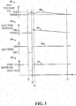
- FIG. 3 shows graphs 300, 310, 320 and 330 illustrating waveforms and state changes in the power conversion system 10 during operation according to the process 200.
- the graph 300 illustrates a DC bus voltage curve 302 representing the voltage Vdc.
- a curve 312 in the graph 310 shows a rectifier setpoint value used by the rectifier controller 62 in regulating the DC bus voltage in the first mode
- a curve 322 in graph 320 shows the operating state (OR) of the rectifier 30 in the first and second modes.
- the graph 330 includes a curve tree 22 showing the control operating state of the inverter 50, which transitions between controlling the AC output in the first mode and controlling or regulating the DC bus voltage in the second mode.
- an abnormal grid condition is detected at time T1
- the controller 60 responds by changing from the first mode operation to the second mode operation, including turning off the rectifier and causing the inverter 50 to control the DC bus voltage.
- the DC bus voltage curve 302 undergoes an increase from T1 through T2 during regulation by the inverter 50.
- the inverter 50 may regulate the DC bus voltage using closed loop control regulation to provide a more stable DC bus voltage level than as shown in the example of FIG. 3 .
- the controller 60 may obtain a measurement of the DC bus voltage Vdc in response to detection of an abnormal grid condition, and use this value as a setpoint reference for regulation by the inverter controller 66 in the second mode.
- the controller 60 detects clearance of the fault condition (YES at 212 in FIG. 2 above), and in response to this fault clearance detection, changes from the second mode to the first mode.
- the controller 60 again measures the DC bus voltage at 214, shown in the graphs 300 and 310 of FIG. 3 as the measured voltage VM.
- the first mode DC bus voltage regulation by the rectifier controller 62 uses a nominal reference voltage or setpoint shown in graphs 300 and 310 as VNOM. Changeover from inverter regulation to rectifier regulation following time T2 may lead to a slight ramp down in the DC bus voltage from T2 through T3 as shown in the curve 302 in FIG. 3 .
- the controller 60 begins the resumption of rectifier-based DC bus voltage regulation at T2 according to a setpoint value that is set to the measured value VM. Thereafter, from T2 through T4, the controller 60 ramps down the setpoint value (e.g., curve 312 in FIG. 3 ) to the nominal value VNOM, and the closed loop regulation of the DC bus voltage curve 302 generally tracks this ramped setpoint. Absent this ramp operation, the rectifier 30 may begin operation at T2 using the nominal setpoint, which can be significantly different from the current operating level of the DC bus circuit 40. In that case, the rectifier control can attempt to overcompensate for the setpoint difference, leading to excessive rectifier currents.
- the setpoint value e.g., curve 312 in FIG. 3
- High rectifier currents can lead to undesired tripping of the motor drive power conversion system 10.
- the regulation of the DC bus voltage during brief or transitory abnormal grid conditions helps to avoid or mitigate undesired tripping based on low DC bus voltage levels in the intermediate circuit 40.
- the concepts of the present disclosure provide advanced abnormal grid condition ride through functions using pre-existing hardware in the motor drive 10 to facilitate continued operation of the system 10 and reduce the likelihood of shutdowns due to overcurrent or under voltage trips during transient grid voltage disturbances or faults.
Landscapes
- Engineering & Computer Science (AREA)
- Power Engineering (AREA)
- Inverter Devices (AREA)
Abstract
Description
- The following relates to motor drives, active front-end power converters, and abnormal grid conditions.
- Various aspects of the present disclosure are now summarized to facilitate a basic understanding of the disclosure, wherein this summary is not an extensive overview of the disclosure, and is intended neither to identify certain elements of the disclosure, nor to delineate the scope thereof. Rather, the primary purpose of this summary is to present various concepts of the disclosure in a simplified form prior to the more detailed description that is presented hereinafter. The present disclosure provides power conversion systems and methods for ride through of abnormal grid conditions or disturbances, in which the system operates in a first or normal mode in which an active rectifier regulates a DC voltage of an intermediate DC circuit, and an inverter converts DC power from the intermediate DC circuit to provide AC output power to drive a load. In response to a detected abnormal grid condition, the system changes to a second mode in which the rectifier is turned off and the inverter regulates the DC voltage of the intermediate DC circuit using power from the load.
-
-
FIG. 1 is a schematic diagram. -
FIG. 2 is a flow diagram. -
FIG. 3 is a waveform diagram. - Referring now in more detail to the figures, several embodiments or implementations are hereinafter described in conjunction with the drawings, wherein like reference numerals are used to refer to like elements throughout, and the various features are not necessarily drawn to scale.
FIG. 1 shows a motor drive typepower conversion system 10 receiving three-phase AC input power from a three-phase source 2, and thedrive 10 operates in a normal operating mode to drive a motor load 4. Although illustrated in the context of three-phase input devices driving a three phase motor load, the disclosed concepts can be employed in multiphase power conversion systems having any number of input and output phases. Themotor drive 10 includes a three-phase LCL input filter circuit 20 coupled between the AC input terminals and AC input terminals of an active or switching rectifier circuit 30 (alternately referred to as a converter). - The drive input 4 has three input phase terminals which are connected through the LCL input filter circuit 20 to the AC input of the
rectifier circuit 30. In other examples L-C filters can be used. In the example ofFIG. 1 , the LCL filter circuit 20 includes inductors L1-L6 as well as Y-connected filter capacitors C1-C3. As seen in the example ofFIG. 1 , the example LCL filter circuit 20 includes three series circuits individually connected between the power converter input 4 and the corresponding phase of the rectifier AC input. Each series circuit includes a pair of filter inductors, with the first circuit including inductor L1 connected to the first power converter input terminal and a second filter inductor L4 connected between L1 and a phase input of therectifier 30". Similarly, the second series circuit includes a first inductor L2 connected to the second power converter input terminal and a second filter inductor L5. The third series circuit includes a first inductor L3 connected to the third power converter input terminal and a third filter inductor L6. In addition, the filter circuit 20 includes three capacitors C1, C2, C3 individually connected between a corresponding one of the filter phases and a common connection point, such as a neutral, as shown. In other examples, the filter capacitors C1-C3 can be connected in a Delta configuration (not shown). - The
drive 10 further includes an intermediateDC bus circuit 40, aninverter 50, and acontroller 60 that includes arectifier control component 62 and aninverter control component 66 to provide rectifier and inverterswitching control signal rectifier 30 and theinverter 50 in various modes as detailed further hereinafter. In other examples, the active front-end (AFE)rectifier 30 can be connected to provide a shared DC output for driving one or more loads, such as a plurality of inverters within a single system. - The
power conversion system 10 includes advanced control capabilities implemented by thecontroller 60 for riding through abnormal grid conditions or other grid disturbances, in which asystem rectifier 30 is operated in a first mode to regulate a DC voltage Vdc of anintermediate DC circuit 40, an inverter is operated in the first mode to convert DC power from theintermediate DC circuit 40 to provide AC output power to drive a load 4. In response to detecting an abnormal grid condition, the system changes to a second mode in which therectifier 30 is turned off and theinverter 50 regulates the DC voltage Vdc of theintermediate DC circuit 40 using the Kinetic energy from the mechanical load 4. In this manner, thecontroller 60 uses kinetic energy from a spinning motor load 4 in order to prop up the DC bus voltage Vdc in theintermediate circuit 40 to help thesystem 10 ride through sagging grid voltages or other abnormal grid condition associated with theAC input source 2. This operation can advantageously enhance robustness and reliability of thepower conversion system 10 during power disturbance transients. In certain examples, thecontroller 60 implements fault detection functionality 68 via aprocessor 64 and programming instructions in an associatedmemory 66 to detect abnormal grid conditions or disturbances. In one example, as shown inFIG. 1 , the fault detection component or function 68 receives one or more sensor signals or values indicating the amplitude of the AC input voltage on one or more of the input lines. In one example, thecontroller 60 selectively identifies abnormal grid conditions when the AC input voltage amplitude drops by a certain threshold amount from an expected level. Other suitable abnormal grid condition detection algorithms and techniques can be used in other embodiments. - In normal operation, the
controller 60 implements motor control functions to convert AC input power from thesource 2 into DC power using therectifier 30, and to convert DC power from theintermediate circuit 40 using theinverter 50 to generate variable frequency, variable amplitude three-phase AC output voltages and currents to drive the motor load 4. Theswitching rectifier 30 includes switching devices S1-S6 individually coupled between a corresponding one of the AC input phases and a corresponding DC bus terminal (DC+ or DC-) of theDC link circuit 40. Thedrive controller 60 includes arectifier controller 62 that operates therectifier 30 in a switching mode according to pulse width modulated (PWM) rectifierswitching control signal 62a provided to the rectifier switches S1-S6 to cause therectifier 30 to convert received three-phase AC input power to provide a DC voltage Vdc across a DC bus capacitance C4 of thelink circuit 40 using any suitable pulse width modulation technique. Theinverter 50 receives DC input power from theintermediate DC circuit 40 and includes inverter switches S7-S12 individually coupled between one of the positive or negative DC bus terminals and a corresponding output phase coupled in this example to the motor load 6. In certain examples, the inverter outputs are connected directly to the leads of the motor load 6. In other examples, one or more intervening components may be connected between the output of theinverter 50 and the motor load 4, such as a filter and/or a transformer (not shown). The inverter switches S7-S12 are operated according to inverterswitching control signals 66a provided by aninverter control component 66 of thedrive controller 60. Thecontroller 60 generates thesignals 66a according to any suitable pulse width modulation technique to convert DC power from thelink circuit 40 to provide variable frequency, variable amplitude AC output power to drive the motor load 4. Theswitching rectifier 30 and theinverter 50 may employ any suitable form of switching devices S1-S12 including without limitation insulated gate bipolar transistors (IGBTs), silicon controlled rectifiers (SCRs), gate turn-off thyristors (GTOs), integrated gate commutated thyristors (IGCTs), etc. - As seen in
FIG. 1 , thecontroller 60 may include one or more components, which may be implemented as software and/or firmware components in execution, programmable logic, etc., including comparison logic operating to compare one or more computer calculated and/or measured values to one or more thresholds to facilitate detection of actual or suspected phase loss conditions. In addition, thecontroller 60 may provide an output signal (not shown) indicating that a phase is lost, and may also indicate which particular phase is lost. Thus, in one implementation, remedial action may be taken, such as shutting down themotor drive 10 and/or providing an alert or warning signal or other indication, for instance, to a user interface associated with themotor drive 10 and/or to a connected network (not shown). -
FIG. 2 shows an example process ormethod 200 to operate a power conversion system. In one possible implementation, themethod 200 can be implemented by thecontroller 60 in order to operate themotor drive 10 shown inFIG. 1 . In general, the process ormethod 200 includes operation in a first or normal mode in which thecontroller 60 operates the rectifier to regulate the DC voltage Vdc of theintermediate circuit 40 while theinverter 50 is operated to convert DC power from thecircuit 40 to provide AC output power to drive themotor load 40. Themethod 200 further includes operation in a second mode, in response to detection of an abnormal grid condition, in which thecontroller 60 turns the switches S1-S6 of therectifier 30 off, and providesswitching control signals 66a to operate theinverter 50 to regulate the DC bus voltage Vdc. Themethod 200 starts in the first or normal operating mode, and thecontroller 60 monitors one or more line voltages at 201. In one example, thecontroller 60 assesses the line voltage to identify dips or sags in the AC input voltages At 202, thecontroller 60 implements the fault detection component 68 (FIG. 1 ) to determine whether an abnormal grid condition has been detected. If not (NO at 202), thecontroller 60 continues normal operating mode at 201 and 202. - If the
controller 60 detects an abnormal grid condition (YES at 202), thecontroller 60 optionally checks if an abnormal grid condition ride through feature is enabled at 204. If so (YES at 202 and 204), thecontroller 60 changes from the first mode to the second mode in response to detecting the abnormal grid condition. This mode switch involves disabling the rectifier switches S1-S6 at 206 (e.g., using thesuitable control signal 62a from therectifier controller 62 inFIG. 1 ). In addition, thecontroller 60 in one implementation measures the DC bus voltage Vdc at 208 at or near the time the fault was detected. At 210, thecontroller 60 employs theinverter controller 66 to provide inverterswitching control signals 66a to operate the switches S7-S12 of theinverter 50 to regulate the DC bus voltage Vdc. In certain examples, the rectifier andinverter controllers inverter controller 66 regulates the DC bus voltage in the second mode to the same setpoint reference value used by therectifier controller 62 in the first mode. In another example, theinverter controller 66 regulates the DC bus voltage at 210 according to the DC bus voltage value measured at 208. Any suitable pulse width modulated switching control algorithm can be used by theinverter controller 66 at 210 in order to selectively transfer power from the rotating motor load 4 to selectively charge the DC bus capacitor C4 in a controlled fashion to regulate the DC bus voltage Vdc. - The
controller 60 in certain examples continues monitoring the input line voltage or voltages while theinverter 50 regulates the DC bus voltage. Thecontroller 60 makes a determination at 212 inFIG. 2 as to whether the previously detected abnormal grid condition or disturbance condition has been cleared. If not (NO at 212), thecontroller 60 continues to operate the inverter controller to regulate the DC bus voltage while therectifier 30 remains off at 210. Once thecontroller 60 determines that the fault condition has been cleared (YES at 212), thecontroller 60 again measures the DC bus voltage at 214. Also, thecontroller 60 switches from the second mode back to the first mode by ceasing or discontinuing DC bus regulation via theinverter 50 at 214 and resuming DC bus regulation via therectifier 30 at 216. In one example, the controller begins rectifier-based DC bus regulation at 216 at the second measured voltage level. Thereafter, thecontroller 60 ramps the DC bus regulation setpoint or reference value up or down to a nominal setpoint value at 218. This advantageously mitigates current spikes associated with abrupt step changes in the operation of therectifier 30 and theinverter 50 in controlling and regulating the DC bus voltage level Vdc. -
FIG. 3 showsgraphs power conversion system 10 during operation according to theprocess 200. Thegraph 300 illustrates a DCbus voltage curve 302 representing the voltage Vdc. Acurve 312 in thegraph 310 shows a rectifier setpoint value used by therectifier controller 62 in regulating the DC bus voltage in the first mode, and acurve 322 ingraph 320 shows the operating state (OR) of therectifier 30 in the first and second modes. Thegraph 330 includes a curve tree 22 showing the control operating state of theinverter 50, which transitions between controlling the AC output in the first mode and controlling or regulating the DC bus voltage in the second mode. In this example, an abnormal grid condition is detected at time T1, and thecontroller 60 responds by changing from the first mode operation to the second mode operation, including turning off the rectifier and causing theinverter 50 to control the DC bus voltage. In the example ofFIG. 3 , the DCbus voltage curve 302 undergoes an increase from T1 through T2 during regulation by theinverter 50. In other examples, theinverter 50 may regulate the DC bus voltage using closed loop control regulation to provide a more stable DC bus voltage level than as shown in the example ofFIG. 3 . As discussed above, moreover, thecontroller 60 may obtain a measurement of the DC bus voltage Vdc in response to detection of an abnormal grid condition, and use this value as a setpoint reference for regulation by theinverter controller 66 in the second mode. - At T2 in
FIG. 3 , thecontroller 60 detects clearance of the fault condition (YES at 212 inFIG. 2 above), and in response to this fault clearance detection, changes from the second mode to the first mode. In the example ofFIG. 2 , thecontroller 60 again measures the DC bus voltage at 214, shown in thegraphs FIG. 3 as the measured voltage VM. As seen inFIG. 3 , the first mode DC bus voltage regulation by therectifier controller 62 uses a nominal reference voltage or setpoint shown ingraphs curve 302 inFIG. 3 . In this example, moreover, thecontroller 60 begins the resumption of rectifier-based DC bus voltage regulation at T2 according to a setpoint value that is set to the measured value VM. Thereafter, from T2 through T4, thecontroller 60 ramps down the setpoint value (e.g.,curve 312 inFIG. 3 ) to the nominal value VNOM, and the closed loop regulation of the DCbus voltage curve 302 generally tracks this ramped setpoint. Absent this ramp operation, therectifier 30 may begin operation at T2 using the nominal setpoint, which can be significantly different from the current operating level of theDC bus circuit 40. In that case, the rectifier control can attempt to overcompensate for the setpoint difference, leading to excessive rectifier currents. High rectifier currents, in turn, can lead to undesired tripping of the motor drivepower conversion system 10. Moreover, the regulation of the DC bus voltage during brief or transitory abnormal grid conditions helps to avoid or mitigate undesired tripping based on low DC bus voltage levels in theintermediate circuit 40. Thus, the concepts of the present disclosure provide advanced abnormal grid condition ride through functions using pre-existing hardware in themotor drive 10 to facilitate continued operation of thesystem 10 and reduce the likelihood of shutdowns due to overcurrent or under voltage trips during transient grid voltage disturbances or faults. - The above examples are merely illustrative of several possible embodiments of various aspects of the present disclosure, wherein equivalent alterations and/or modifications will occur to others skilled in the art upon reading and understanding this specification and the annexed drawings. In particular regard to the various functions performed by the above described components (assemblies, devices, systems, circuits, and the like), the terms (including a reference to a "means") used to describe such components are intended to correspond, unless otherwise indicated, to any component, such as hardware, processor-executed software, or combinations thereof, which performs the specified function of the described component (i.e., that is functionally equivalent), even though not structurally equivalent to the disclosed structure which performs the function in the illustrated implementations of the disclosure. In addition, although a particular feature of the disclosure may have been disclosed with respect to only one of several implementations, such feature may be combined with one or more other features of the other implementations as may be desired and advantageous for any given or particular application. Also, to the extent that the terms "including," "includes," "having," "has," "with," or variants thereof are used in the detailed description and/or in the claims, such terms are intended to be inclusive in a manner similar to the term "comprising." In the preceding specification, various embodiments have been described with reference to the accompanying drawings. It will, however, be evident that various modifications and changes may be made thereto, and additional embodiments may be implemented, without departing from the broader scope of the invention as set forth in the claims that follow. The specification and drawings are accordingly to be regarded in an illustrative rather than restrictive sense.
- The following is a list of further preferred embodiments of the invention:
- Embodiment 1. A power conversion system, comprising:
- an AC input coupleable to receive AC input power from a power source;
- a rectifier, including a plurality of AC input terminals, first and second DC output terminals, and a plurality of rectifier switching devices individually coupled between a corresponding one of the AC input terminals and one of the first and second DC output terminals;
- a filter circuit coupled between the AC input and the rectifier;
- an inverter, including first and second DC input terminals, a plurality of AC output terminals, and a plurality of inverter switching devices individually coupled between a corresponding one of the DC input terminals and one of the AC output terminals;
- an intermediate DC circuit including a capacitor coupled between the first and second DC output terminals of the rectifier; and
- a controller operative in a first mode to provide rectifier switching control signals to operate the rectifier switching devices to regulate a DC voltage of the intermediate DC circuit, and to provide inverter switching control signals to operate the inverter switching devices to convert DC power from the intermediate DC circuit to provide AC output power to the AC output terminals;
- wherein the controller is operative in a second mode to provide the rectifier switching control signals to turn the rectifier switching devices off, and to provide the inverter switching control signals to operate the inverter switching devices to regulate the DC voltage of the intermediate DC circuit.
-
Embodiment 2. The power conversion system of embodiment 1, wherein the controller is operative to detect an abnormal grid condition, and to change from the first mode to the second mode in response to detection of the abnormal grid condition. -
Embodiment 3. The power conversion system ofembodiment 2, wherein the controller is operative to detect clearance of the abnormal grid condition, and to change from the second mode to the first mode in response to detection of clearance of the abnormal grid condition. - Embodiment 4. The power conversion system of
embodiment 3,
wherein the controller is operative in the first mode to provide the rectifier switching control signals to operate the rectifier switching devices to regulate the DC voltage of the intermediate DC circuit according to a setpoint value; and
wherein the controller is operative to:- measure the DC voltage in response to detection of clearance of the abnormal grid condition,
- initially set the setpoint value to the measured DC voltage value when changing from the second mode to the first mode, and
- ramp the setpoint value to a nominal setpoint value after changing from the second mode to the first mode.
- Embodiment 5. The power conversion system of embodiment 4, wherein the controller is operative in the second mode to provide the inverter switching control signals to operate the inverter switching devices to regulate the DC voltage of the intermediate DC circuit according to a value of the DC voltage measured in response to detection of the abnormal grid condition.
- Embodiment 6. The power conversion system of
embodiment 3, wherein the controller is operative in the second mode to provide the inverter switching control signals to operate the inverter switching devices to regulate the DC voltage of the intermediate DC circuit according to a value of the DC voltage measured in response to detection of the abnormal grid condition. - Embodiment 7. The power conversion system of
embodiment 2, wherein the controller is operative in the second mode to provide the inverter switching control signals to operate the inverter switching devices to regulate the DC voltage of the intermediate DC circuit according to a value of the DC voltage measured in response to detection of an abnormal grid condition. -
Embodiment 8. The power conversion system of embodiment 1, wherein the controller is operative to detect clearance of an abnormal grid condition, and to change from the second mode to the first mode in response to detection of clearance of the abnormal grid condition. - Embodiment 9. The power conversion system of
embodiment 8,
wherein the controller is operative in the first mode to provide the rectifier switching control signals to operate the rectifier switching devices to regulate the DC voltage of the intermediate DC circuit according to a setpoint value; and
wherein the controller is operative to:- measure the DC voltage in response to detection of clearance of the abnormal grid condition,
- initially set the setpoint value to the measured DC voltage value when changing from the second mode to the first mode, and
- ramp the setpoint value to a nominal setpoint value after changing from the second mode to the first mode.
-
Embodiment 10. The power conversion system of embodiment 9, wherein the controller is operative in the second mode to provide the inverter switching control signals to operate the inverter switching devices to regulate the DC voltage of the intermediate DC circuit according to a value of the DC voltage measured in response to detection of the abnormal grid condition. - Embodiment 11. The power conversion system of
embodiment 8, wherein the controller is operative in the second mode to provide the inverter switching control signals to operate the inverter switching devices to regulate the DC voltage of the intermediate DC circuit according to a value of the DC voltage measured in response to detection of the abnormal grid condition. - Embodiment 12. The power conversion system of embodiment 1, wherein the controller is operative in the second mode to provide the inverter switching control signals to operate the inverter switching devices to regulate the DC voltage of the intermediate DC circuit according to a value of the DC voltage measured in response to detection of an abnormal grid condition.
-
Embodiment 13. A method to operate a power conversion system having rectifier, an inverter and, an intermediate DC circuit coupled between the rectifier and the inverter, the method comprising:- in a first mode:
- operating the rectifier to regulate a DC voltage of the intermediate DC circuit, and
- operating the inverter to convert DC power from the intermediate DC circuit to provide AC output power to drive a load; and
- in a second mode:
- turning the rectifier off, and
- operating the inverter to regulate the DC voltage of the intermediate DC circuit using power from the load.
- in a first mode:
- Embodiment 14. The method of
embodiment 13, further comprising:- detecting an abnormal grid condition;
- changing from the first mode to the second mode in response to detecting the abnormal grid condition;
- detecting clearance of the abnormal grid condition; and
- changing from the second mode to the first mode in response to detecting clearance of the abnormal grid condition.
- Embodiment 15. The method of embodiment 14, further comprising:
- in the first mode, operating the rectifier to regulate the DC voltage according to a setpoint value;
- measuring the DC voltage in response to detecting clearance of the abnormal grid condition condition;
- initially setting the setpoint value to the measured DC voltage value when changing from the second mode to the first mode; and
- ramping the setpoint value to a nominal setpoint value after changing from the second mode to the first mode.
- Embodiment 16. The method of embodiment 14, further comprising:
- in the second mode, operating the inverter to regulate the DC voltage according to a value of the DC voltage measured in response to detecting an abnormal grid condition.
- Embodiment 17. A non-transitory computer readable medium with computer executable instructions to operate a power conversion system having rectifier, an inverter and, an intermediate DC circuit coupled between the rectifier and the inverter, the computer readable medium comprising computer executable instructions for:
- in a first mode:
- operating the rectifier to regulate a DC voltage of the intermediate DC circuit, and
- operating the inverter to convert DC power from the intermediate DC circuit to provide AC output power to drive a load; and
- in a second mode:
- turning the rectifier off, and
- operating the inverter to regulate the DC voltage of the intermediate DC circuit using power from the load.
- Embodiment 18. The non-transitory computer readable medium of embodiment 17, further comprising computer executable instructions for:
- detecting an abnormal grid condition;
- changing from the first mode to the second mode in response to detecting the abnormal grid condition;
- detecting clearance of the abnormal grid condition; and
- changing from the second mode to the first mode in response to detecting clearance of the abnormal grid condition.
- in a first mode:
- Embodiment 19. The non-transitory computer readable medium of embodiment 18, further comprising computer executable instructions for:
- in the first mode, operating the rectifier to regulate the DC voltage according to a setpoint value;
- measuring the DC voltage in response to detecting clearance of the abnormal grid condition;
- initially setting the setpoint value to the measured DC voltage value when changing from the second mode to the first mode; and
- ramping the setpoint value to a nominal setpoint value after changing from the second mode to the first mode.
- Embodiment 20. The non-transitory computer readable medium of embodiment 17, further comprising computer executable instructions for:
- in the second mode, operating the inverter to regulate the DC voltage according to a value of the DC voltage measured in response to detecting an abnormal grid condition.
Claims (15)
- A power conversion system, comprising:an AC input coupleable to receive AC input power from a power source;a rectifier, including a plurality of AC input terminals, first and second DC output terminals, and a plurality of rectifier switching devices individually coupled between a corresponding one of the AC input terminals and one of the first and second DC output terminals;a filter circuit coupled between the AC input and the rectifier;an inverter, including first and second DC input terminals, a plurality of AC output terminals, and a plurality of inverter switching devices individually coupled between a corresponding one of the DC input terminals and one of the AC output terminals;an intermediate DC circuit including a capacitor coupled between the first and second DC output terminals of the rectifier; anda controller operative in a first mode to provide rectifier switching control signals to operate the rectifier switching devices to regulate a DC voltage of the intermediate DC circuit, and to provide inverter switching control signals to operate the inverter switching devices to convert DC power from the intermediate DC circuit to provide AC output power to the AC output terminals;wherein the controller is operative in a second mode to provide the rectifier switching control signals to turn the rectifier switching devices off, and to provide the inverter switching control signals to operate the inverter switching devices to regulate the DC voltage of the intermediate DC circuit.
- The power conversion system of claim 1, wherein the controller is operative to detect an abnormal grid condition, and to change from the first mode to the second mode in response to detection of the abnormal grid condition.
- The power conversion system of claim 2, wherein the controller is operative to detect clearance of the abnormal grid condition, and to change from the second mode to the first mode in response to detection of clearance of the abnormal grid condition.
- The power conversion system of claim 3,
wherein the controller is operative in the first mode to provide the rectifier switching control signals to operate the rectifier switching devices to regulate the DC voltage of the intermediate DC circuit according to a setpoint value; and
wherein the controller is operative to:measure the DC voltage in response to detection of clearance of the abnormal grid condition,initially set the setpoint value to the measured DC voltage value when changing from the second mode to the first mode, andramp the setpoint value to a nominal setpoint value after changing from the second mode to the first mode. - The power conversion system of claim 1, wherein the controller is operative to detect clearance of an abnormal grid condition, and to change from the second mode to the first mode in response to detection of clearance of the abnormal grid condition.
- The power conversion system of claim 5,
wherein the controller is operative in the first mode to provide the rectifier switching control signals to operate the rectifier switching devices to regulate the DC voltage of the intermediate DC circuit according to a setpoint value; and
wherein the controller is operative to:measure the DC voltage in response to detection of clearance of the abnormal grid condition,initially set the setpoint value to the measured DC voltage value when changing from the second mode to the first mode, andramp the setpoint value to a nominal setpoint value after changing from the second mode to the first mode. - The power conversion system of one of claims 1 to 6, wherein the controlled is operative in the second mode to provide the inverter switching control signals to operate the inverter switching devices to regulate the DC voltage of the intermediate DC circuit according to a value of the DC voltage measured in response to detection of an abnormal grid condition.
- A method to operate a power conversion system having rectifier, an inverter and, an intermediate DC circuit coupled between the rectifier and the inverter, the method comprising:in a first mode:operating the rectifier to regulate a DC voltage of the intermediate DC circuit, andoperating the inverter to convert DC power from the intermediate DC circuit to provide AC output power to drive a load; andin a second mode:turning the rectifier off, andoperating the inverter to regulate the DC voltage of the intermediate DC circuit using power from the load.
- The method of claim 8, further comprising:detecting an abnormal grid condition;changing from the first mode to the second mode in response to detecting the abnormal grid condition;detecting clearance of the abnormal grid condition; andchanging from the second mode to the first mode in response to detecting clearance of the abnormal grid condition.
- The method of claim 9, further comprising:in the first mode, operating the rectifier to regulate the DC voltage according to a setpoint value;measuring the DC voltage in response to detecting clearance of the abnormal grid condition;initially setting the setpoint value to the measured DC voltage value when changing from the second mode to the first mode; andramping the setpoint value to a nominal setpoint value after changing from the second mode to the first mode.
- The method of claim 9, further comprising:in the second mode, operating the inverter to regulate the DC voltage according to a value of the DC voltage measured in response to detecting an abnormal grid condition.
- A non-transitory computer readable medium with computer executable instructions to operate a power conversion system having rectifier, an inverter and, an intermediate DC circuit coupled between the rectifier and the inverter, the computer readable medium comprising computer executable instructions for:in a first mode:operating the rectifier to regulate a DC voltage of the intermediate DC circuit, andoperating the inverter to convert DC power from the intermediate DC circuit to provide AC output power to drive a load; andin a second mode:turning the rectifier off, andoperating the inverter to regulate the DC voltage of the intermediate DC circuit using power from the load.
- The non-transitory computer readable medium of claim 12, further comprising computer executable instructions for:detecting an abnormal grid condition;changing from the first mode to the second mode in response to detecting the abnormal grid condition;detecting clearance of the abnormal grid condition; andchanging from the second mode to the first mode in response to detecting clearance of the abnormal grid condition.
- The non-transitory computer readable medium of claim 13, further comprising computer executable instructions for:in the first mode, operating the rectifier to regulate the DC voltage according to a setpoint value;measuring the DC voltage in response to detecting clearance of the abnormal grid condition;initially setting the setpoint value to the measured DC voltage value when changing from the second mode to the first mode; andramping the setpoint value to a nominal setpoint value after changing from the second mode to the first mode.
- The non-transitory computer readable medium of claim 12, further comprising computer executable instructions for:in the second mode, operating the inverter to regulate the DC voltage according to a value of the DC voltage measured in response to detecting an abnormal grid condition.
Applications Claiming Priority (1)
| Application Number | Priority Date | Filing Date | Title |
|---|---|---|---|
| US15/152,961 US9847733B2 (en) | 2016-05-12 | 2016-05-12 | Power conversion system with DC bus regulation for abnormal grid condition ride through |
Publications (2)
| Publication Number | Publication Date |
|---|---|
| EP3244521A1 true EP3244521A1 (en) | 2017-11-15 |
| EP3244521B1 EP3244521B1 (en) | 2021-08-11 |
Family
ID=58669711
Family Applications (1)
| Application Number | Title | Priority Date | Filing Date |
|---|---|---|---|
| EP17169431.8A Active EP3244521B1 (en) | 2016-05-12 | 2017-05-04 | Power conversion system with dc bus regulation for abnormal grid condition ride through |
Country Status (3)
| Country | Link |
|---|---|
| US (1) | US9847733B2 (en) |
| EP (1) | EP3244521B1 (en) |
| CN (1) | CN107370389B (en) |
Cited By (1)
| Publication number | Priority date | Publication date | Assignee | Title |
|---|---|---|---|---|
| CN111799787A (en) * | 2020-07-13 | 2020-10-20 | 重庆理工大学 | An Analysis Method of Power Grid Comprehensive Load System |
Families Citing this family (5)
| Publication number | Priority date | Publication date | Assignee | Title |
|---|---|---|---|---|
| GB201610369D0 (en) * | 2016-06-15 | 2016-07-27 | Rolls Royce Plc | Control of an electrical converter |
| RU2686475C1 (en) * | 2018-04-25 | 2019-04-29 | Фёдор Андреевич Гельвер | Frequency converter with asymmetric inverter circuit |
| DE102019118927A1 (en) * | 2019-07-12 | 2021-01-14 | Vacon Oy | DC link charging arrangement and method for charging a DC link capacitor |
| US11146180B2 (en) | 2019-11-01 | 2021-10-12 | Rockwell Automation Technologies, Inc. | Linear and nonlinear dynamic bus control for AFE applications |
| CN113629703B (en) * | 2021-07-28 | 2024-05-07 | 南方电网科学研究院有限责任公司 | An Optimization Method for Fault Recovery Control of Conventional DC System |
Citations (2)
| Publication number | Priority date | Publication date | Assignee | Title |
|---|---|---|---|---|
| WO2009116235A1 (en) * | 2008-03-17 | 2009-09-24 | ダイキン工業株式会社 | Power conversion device |
| US20130134910A1 (en) * | 2011-11-30 | 2013-05-30 | Fanuc Corporation | Motor drive apparatus having power failure detection unit for determining presence or absence of power failure |
Family Cites Families (41)
| Publication number | Priority date | Publication date | Assignee | Title |
|---|---|---|---|---|
| US3757197A (en) | 1972-07-25 | 1973-09-04 | Gen Electric | Amping voltage on series compensating capacitor series parallel compensated current source inverter with means for cl |
| JPS605151B2 (en) | 1978-04-05 | 1985-02-08 | 株式会社日立製作所 | Control method for multiplexed current source inverter |
| US4434376A (en) | 1979-07-23 | 1984-02-28 | Electric Power Research Institute, Inc. | Method and means for damping subsynchronous oscillations and DC offset in an AC power system |
| US4496899A (en) | 1983-06-28 | 1985-01-29 | General Electric Company | Control for a force commutated current source var generator |
| US4545002A (en) | 1983-06-28 | 1985-10-01 | General Electric Company | Thyristor voltage limiter for current source inverter |
| US4833389A (en) | 1988-09-26 | 1989-05-23 | Westinghouse Electric Corp. | Current source inverter control system for load commutated induction motor drive |
| US4870338A (en) | 1988-09-26 | 1989-09-26 | Westinghouse Electric Corp. | Load commutated inverter (LCI) induction motor drive |
| US5005115A (en) | 1989-07-28 | 1991-04-02 | Westinghouse Electric Corp. | Forced-commutated current-source converter and AC motor drive using the same |
| US5041959A (en) | 1990-08-14 | 1991-08-20 | General Electric Company | Control system for a current source converter supplying an AC bus |
| GB2298533A (en) | 1994-07-29 | 1996-09-04 | Texas Instruments Ltd | Overvoltage protector |
| DE19821887B4 (en) * | 1997-05-20 | 2015-03-05 | Kimo Industrie-Elektronik Gmbh | Method for operating a converter circuit arrangement for controlling an electric motor |
| AU2675799A (en) | 1998-02-13 | 1999-08-30 | The Texas A & M University System | Method and system for ride-through of an adjustable speed drive for voltage sagsand short-term power interruptions |
| US6118676A (en) | 1998-11-06 | 2000-09-12 | Soft Switching Technologies Corp. | Dynamic voltage sag correction |
| US6275391B1 (en) | 2000-04-06 | 2001-08-14 | General Electric Company | Compact push-pull converter and crowbar circuit, and control therefor |
| US6686718B2 (en) | 2001-11-27 | 2004-02-03 | York International Corp. | Control loop and method for variable speed drive ride-through capability improvement |
| AU2003206633B2 (en) | 2002-01-29 | 2006-11-02 | Vestas Wind Systems A/S | Circuit to be used in a wind power plant |
| US7129599B2 (en) | 2002-10-15 | 2006-10-31 | Soft Switching Technologies Corporation | Dual feed power supply systems with enhanced power quality |
| FI116174B (en) | 2003-04-08 | 2005-09-30 | Abb Oy | Configuration and Method for Protecting Directional Devices |
| CA2518074C (en) | 2003-05-02 | 2011-07-26 | Xantrex Technology Inc. | Control system for doubly fed induction generator |
| DE60317183T2 (en) | 2003-07-15 | 2008-06-26 | Gamesa Innovation & Technology, S.L. Unipersonal | Control and protection device for a double-fed induction generator system |
| US7164254B2 (en) | 2005-02-28 | 2007-01-16 | Rockwell Automation Technologies, Inc. | Modulation methods and apparatus for reducing common mode voltages |
| US7173399B2 (en) | 2005-04-19 | 2007-02-06 | General Electric Company | Integrated torsional mode damping system and method |
| EP1883880A4 (en) | 2005-05-24 | 2010-05-05 | Satcon Technology Corp | Device, system, and method for providing a low-voltage fault ride-through for a wind generator farm |
| US7081734B1 (en) * | 2005-09-02 | 2006-07-25 | York International Corporation | Ride-through method and system for HVACandR chillers |
| ES2296483B1 (en) | 2005-11-21 | 2009-03-01 | Ingeteam Technology, S.A. | A CONTROL AND PROTECTION SYSTEM BEFORE SYMBOLIC AND ASYMETRIC FAULTS, FOR ASYNCHRONOUS GENERATORS. |
| US7253537B2 (en) | 2005-12-08 | 2007-08-07 | General Electric Company | System and method of operating double fed induction generators |
| US7423412B2 (en) | 2006-01-31 | 2008-09-09 | General Electric Company | Method, apparatus and computer program product for injecting current |
| US7193387B1 (en) | 2006-03-14 | 2007-03-20 | Rockwell Automation Technologies, Inc. | System and method for motor speed estimation using hybrid model reference adaptive system |
| US7649756B2 (en) | 2006-05-17 | 2010-01-19 | Rockwell Automation Technologies, Inc. | Common mode noise reduction in converter systems through modification of single phase switching signal |
| US7358700B2 (en) | 2006-09-14 | 2008-04-15 | Rockwell Automation Technologies, Inc. | Induction motor controller |
| US7622815B2 (en) | 2006-12-29 | 2009-11-24 | Ingeteam Energy, S.A. | Low voltage ride through system for a variable speed wind turbine having an exciter machine and a power converter not connected to the grid |
| US8203304B2 (en) | 2007-08-31 | 2012-06-19 | Rockwell Automation Technologies, Inc. | Control method and system with feedback indicative of load flux |
| US8030791B2 (en) | 2008-07-31 | 2011-10-04 | Rockwell Automation Technologies, Inc. | Current source converter-based wind energy system |
| CN101383576B (en) | 2008-10-28 | 2010-12-29 | 华北电力大学(保定) | A method for large-scale wind power generators to ride through low-voltage faults in power grids |
| US8259426B2 (en) * | 2010-05-28 | 2012-09-04 | Rockwell Automation Technologies, Inc. | Variable frequency drive and methods for filter capacitor fault detection |
| WO2012055416A1 (en) | 2010-10-28 | 2012-05-03 | Vestas Wind Systems A/S | A wind turbine generator |
| US8570003B2 (en) | 2011-04-13 | 2013-10-29 | Rockwell Automation Technologies, Inc. | Double fed induction generator converter and method for suppressing transient in deactivation of crowbar circuit for grid fault ridethrough |
| CN102214931B (en) | 2011-05-24 | 2014-06-11 | 浙江大学 | Device and method for low voltage ride through of double-fed inductive wind power generator system |
| US8907510B2 (en) * | 2012-03-09 | 2014-12-09 | General Electric Company | Method and systems for operating a wind turbine |
| US9041234B2 (en) | 2012-03-26 | 2015-05-26 | Rockwell Automation Technologies, Inc. | Double fed induction generator (DFIG) converter and method for improved grid fault ridethrough |
| WO2013159306A1 (en) * | 2012-04-26 | 2013-10-31 | General Electric Company | Power converter system, damping system, and method of operating power converter system |
-
2016
- 2016-05-12 US US15/152,961 patent/US9847733B2/en active Active
-
2017
- 2017-05-04 EP EP17169431.8A patent/EP3244521B1/en active Active
- 2017-05-12 CN CN201710333799.XA patent/CN107370389B/en active Active
Patent Citations (2)
| Publication number | Priority date | Publication date | Assignee | Title |
|---|---|---|---|---|
| WO2009116235A1 (en) * | 2008-03-17 | 2009-09-24 | ダイキン工業株式会社 | Power conversion device |
| US20130134910A1 (en) * | 2011-11-30 | 2013-05-30 | Fanuc Corporation | Motor drive apparatus having power failure detection unit for determining presence or absence of power failure |
Cited By (2)
| Publication number | Priority date | Publication date | Assignee | Title |
|---|---|---|---|---|
| CN111799787A (en) * | 2020-07-13 | 2020-10-20 | 重庆理工大学 | An Analysis Method of Power Grid Comprehensive Load System |
| CN111799787B (en) * | 2020-07-13 | 2023-06-20 | 重庆理工大学 | An Analysis Method of Integrated Load System of Power Network |
Also Published As
| Publication number | Publication date |
|---|---|
| EP3244521B1 (en) | 2021-08-11 |
| US9847733B2 (en) | 2017-12-19 |
| CN107370389A (en) | 2017-11-21 |
| CN107370389B (en) | 2019-06-28 |
| US20170331389A1 (en) | 2017-11-16 |
Similar Documents
| Publication | Publication Date | Title |
|---|---|---|
| EP3244521B1 (en) | Power conversion system with dc bus regulation for abnormal grid condition ride through | |
| US8937796B2 (en) | Variable frequency drive and methods for filter capacitor fault detection | |
| US20180109201A1 (en) | Active neutral point clamped converter control system and method | |
| AU2017336112B2 (en) | Control device for power converter | |
| US9431923B2 (en) | Power converter | |
| US11128237B2 (en) | Electrically coupling a first electrical supply network to a second electrical supply network | |
| CN112840522B (en) | Power supply device and abnormality detection method of AC power supply | |
| US12113395B2 (en) | Power converter | |
| JP2010239736A (en) | Power converter | |
| US11283369B2 (en) | Control device and power control system | |
| US20150188454A1 (en) | Inverter device, control circuit for inverter device, and method for controlling inverter device | |
| CN114447979B (en) | A power conversion device and a control method for the power conversion device | |
| US12224621B2 (en) | Power supply device | |
| JP5302905B2 (en) | Power converter | |
| US10848072B2 (en) | Power supply control device, power conversion system, and power supply control method | |
| CN112534695B (en) | Methods for controlling MMC | |
| JP3773798B2 (en) | Power converter | |
| US9425702B2 (en) | System and method for safe switching in an AC-to-AC converter | |
| US12537471B2 (en) | Power converter, motor drive system, and power conversion method | |
| EP3584916B1 (en) | Method for controlling inverter | |
| JP4235910B2 (en) | Winding induction motor controller | |
| JP2025096739A (en) | Control device and control method for power conversion device | |
| KR20160050544A (en) | Apparatus for controlling inverter | |
| CN117674035A (en) | DC transmission system fault accelerated recovery control method, device, equipment and medium | |
| CN114641915A (en) | Uninterruptible power supply device |
Legal Events
| Date | Code | Title | Description |
|---|---|---|---|
| PUAI | Public reference made under article 153(3) epc to a published international application that has entered the european phase |
Free format text: ORIGINAL CODE: 0009012 |
|
| STAA | Information on the status of an ep patent application or granted ep patent |
Free format text: STATUS: THE APPLICATION HAS BEEN PUBLISHED |
|
| AK | Designated contracting states |
Kind code of ref document: A1 Designated state(s): AL AT BE BG CH CY CZ DE DK EE ES FI FR GB GR HR HU IE IS IT LI LT LU LV MC MK MT NL NO PL PT RO RS SE SI SK SM TR |
|
| AX | Request for extension of the european patent |
Extension state: BA ME |
|
| STAA | Information on the status of an ep patent application or granted ep patent |
Free format text: STATUS: REQUEST FOR EXAMINATION WAS MADE |
|
| 17P | Request for examination filed |
Effective date: 20180515 |
|
| RBV | Designated contracting states (corrected) |
Designated state(s): AL AT BE BG CH CY CZ DE DK EE ES FI FR GB GR HR HU IE IS IT LI LT LU LV MC MK MT NL NO PL PT RO RS SE SI SK SM TR |
|
| STAA | Information on the status of an ep patent application or granted ep patent |
Free format text: STATUS: EXAMINATION IS IN PROGRESS |
|
| 17Q | First examination report despatched |
Effective date: 20190404 |
|
| GRAP | Despatch of communication of intention to grant a patent |
Free format text: ORIGINAL CODE: EPIDOSNIGR1 |
|
| STAA | Information on the status of an ep patent application or granted ep patent |
Free format text: STATUS: GRANT OF PATENT IS INTENDED |
|
| RIC1 | Information provided on ipc code assigned before grant |
Ipc: H02P 29/024 20160101ALI20210121BHEP Ipc: H02P 29/00 20160101ALI20210121BHEP Ipc: H02P 27/06 20060101ALI20210121BHEP Ipc: H02M 5/458 20060101ALI20210121BHEP Ipc: H02M 1/08 20060101ALN20210121BHEP Ipc: H02M 1/32 20070101AFI20210121BHEP |
|
| RIC1 | Information provided on ipc code assigned before grant |
Ipc: H02P 27/06 20060101ALI20210126BHEP Ipc: H02M 1/32 20070101AFI20210126BHEP Ipc: H02P 29/00 20160101ALI20210126BHEP Ipc: H02P 29/024 20160101ALI20210126BHEP Ipc: H02M 1/08 20060101ALN20210126BHEP Ipc: H02M 5/458 20060101ALI20210126BHEP |
|
| INTG | Intention to grant announced |
Effective date: 20210212 |
|
| GRAS | Grant fee paid |
Free format text: ORIGINAL CODE: EPIDOSNIGR3 |
|
| GRAA | (expected) grant |
Free format text: ORIGINAL CODE: 0009210 |
|
| STAA | Information on the status of an ep patent application or granted ep patent |
Free format text: STATUS: THE PATENT HAS BEEN GRANTED |
|
| AK | Designated contracting states |
Kind code of ref document: B1 Designated state(s): AL AT BE BG CH CY CZ DE DK EE ES FI FR GB GR HR HU IE IS IT LI LT LU LV MC MK MT NL NO PL PT RO RS SE SI SK SM TR |
|
| REG | Reference to a national code |
Ref country code: CH Ref legal event code: EP |
|
| REG | Reference to a national code |
Ref country code: DE Ref legal event code: R096 Ref document number: 602017043692 Country of ref document: DE |
|
| REG | Reference to a national code |
Ref country code: IE Ref legal event code: FG4D Ref country code: AT Ref legal event code: REF Ref document number: 1420412 Country of ref document: AT Kind code of ref document: T Effective date: 20210915 |
|
| REG | Reference to a national code |
Ref country code: LT Ref legal event code: MG9D |
|
| REG | Reference to a national code |
Ref country code: NL Ref legal event code: MP Effective date: 20210811 |
|
| REG | Reference to a national code |
Ref country code: AT Ref legal event code: MK05 Ref document number: 1420412 Country of ref document: AT Kind code of ref document: T Effective date: 20210811 |
|
| PG25 | Lapsed in a contracting state [announced via postgrant information from national office to epo] |
Ref country code: RS Free format text: LAPSE BECAUSE OF FAILURE TO SUBMIT A TRANSLATION OF THE DESCRIPTION OR TO PAY THE FEE WITHIN THE PRESCRIBED TIME-LIMIT Effective date: 20210811 Ref country code: SE Free format text: LAPSE BECAUSE OF FAILURE TO SUBMIT A TRANSLATION OF THE DESCRIPTION OR TO PAY THE FEE WITHIN THE PRESCRIBED TIME-LIMIT Effective date: 20210811 Ref country code: FI Free format text: LAPSE BECAUSE OF FAILURE TO SUBMIT A TRANSLATION OF THE DESCRIPTION OR TO PAY THE FEE WITHIN THE PRESCRIBED TIME-LIMIT Effective date: 20210811 Ref country code: ES Free format text: LAPSE BECAUSE OF FAILURE TO SUBMIT A TRANSLATION OF THE DESCRIPTION OR TO PAY THE FEE WITHIN THE PRESCRIBED TIME-LIMIT Effective date: 20210811 Ref country code: HR Free format text: LAPSE BECAUSE OF FAILURE TO SUBMIT A TRANSLATION OF THE DESCRIPTION OR TO PAY THE FEE WITHIN THE PRESCRIBED TIME-LIMIT Effective date: 20210811 Ref country code: PT Free format text: LAPSE BECAUSE OF FAILURE TO SUBMIT A TRANSLATION OF THE DESCRIPTION OR TO PAY THE FEE WITHIN THE PRESCRIBED TIME-LIMIT Effective date: 20211213 Ref country code: NO Free format text: LAPSE BECAUSE OF FAILURE TO SUBMIT A TRANSLATION OF THE DESCRIPTION OR TO PAY THE FEE WITHIN THE PRESCRIBED TIME-LIMIT Effective date: 20211111 Ref country code: AT Free format text: LAPSE BECAUSE OF FAILURE TO SUBMIT A TRANSLATION OF THE DESCRIPTION OR TO PAY THE FEE WITHIN THE PRESCRIBED TIME-LIMIT Effective date: 20210811 Ref country code: BG Free format text: LAPSE BECAUSE OF FAILURE TO SUBMIT A TRANSLATION OF THE DESCRIPTION OR TO PAY THE FEE WITHIN THE PRESCRIBED TIME-LIMIT Effective date: 20211111 Ref country code: LT Free format text: LAPSE BECAUSE OF FAILURE TO SUBMIT A TRANSLATION OF THE DESCRIPTION OR TO PAY THE FEE WITHIN THE PRESCRIBED TIME-LIMIT Effective date: 20210811 |
|
| PG25 | Lapsed in a contracting state [announced via postgrant information from national office to epo] |
Ref country code: PL Free format text: LAPSE BECAUSE OF FAILURE TO SUBMIT A TRANSLATION OF THE DESCRIPTION OR TO PAY THE FEE WITHIN THE PRESCRIBED TIME-LIMIT Effective date: 20210811 Ref country code: LV Free format text: LAPSE BECAUSE OF FAILURE TO SUBMIT A TRANSLATION OF THE DESCRIPTION OR TO PAY THE FEE WITHIN THE PRESCRIBED TIME-LIMIT Effective date: 20210811 Ref country code: GR Free format text: LAPSE BECAUSE OF FAILURE TO SUBMIT A TRANSLATION OF THE DESCRIPTION OR TO PAY THE FEE WITHIN THE PRESCRIBED TIME-LIMIT Effective date: 20211112 |
|
| PG25 | Lapsed in a contracting state [announced via postgrant information from national office to epo] |
Ref country code: NL Free format text: LAPSE BECAUSE OF FAILURE TO SUBMIT A TRANSLATION OF THE DESCRIPTION OR TO PAY THE FEE WITHIN THE PRESCRIBED TIME-LIMIT Effective date: 20210811 |
|
| PG25 | Lapsed in a contracting state [announced via postgrant information from national office to epo] |
Ref country code: DK Free format text: LAPSE BECAUSE OF FAILURE TO SUBMIT A TRANSLATION OF THE DESCRIPTION OR TO PAY THE FEE WITHIN THE PRESCRIBED TIME-LIMIT Effective date: 20210811 |
|
| REG | Reference to a national code |
Ref country code: DE Ref legal event code: R097 Ref document number: 602017043692 Country of ref document: DE |
|
| PG25 | Lapsed in a contracting state [announced via postgrant information from national office to epo] |
Ref country code: SM Free format text: LAPSE BECAUSE OF FAILURE TO SUBMIT A TRANSLATION OF THE DESCRIPTION OR TO PAY THE FEE WITHIN THE PRESCRIBED TIME-LIMIT Effective date: 20210811 Ref country code: SK Free format text: LAPSE BECAUSE OF FAILURE TO SUBMIT A TRANSLATION OF THE DESCRIPTION OR TO PAY THE FEE WITHIN THE PRESCRIBED TIME-LIMIT Effective date: 20210811 Ref country code: RO Free format text: LAPSE BECAUSE OF FAILURE TO SUBMIT A TRANSLATION OF THE DESCRIPTION OR TO PAY THE FEE WITHIN THE PRESCRIBED TIME-LIMIT Effective date: 20210811 Ref country code: EE Free format text: LAPSE BECAUSE OF FAILURE TO SUBMIT A TRANSLATION OF THE DESCRIPTION OR TO PAY THE FEE WITHIN THE PRESCRIBED TIME-LIMIT Effective date: 20210811 Ref country code: CZ Free format text: LAPSE BECAUSE OF FAILURE TO SUBMIT A TRANSLATION OF THE DESCRIPTION OR TO PAY THE FEE WITHIN THE PRESCRIBED TIME-LIMIT Effective date: 20210811 Ref country code: AL Free format text: LAPSE BECAUSE OF FAILURE TO SUBMIT A TRANSLATION OF THE DESCRIPTION OR TO PAY THE FEE WITHIN THE PRESCRIBED TIME-LIMIT Effective date: 20210811 |
|
| PLBE | No opposition filed within time limit |
Free format text: ORIGINAL CODE: 0009261 |
|
| STAA | Information on the status of an ep patent application or granted ep patent |
Free format text: STATUS: NO OPPOSITION FILED WITHIN TIME LIMIT |
|
| 26N | No opposition filed |
Effective date: 20220512 |
|
| PG25 | Lapsed in a contracting state [announced via postgrant information from national office to epo] |
Ref country code: IT Free format text: LAPSE BECAUSE OF FAILURE TO SUBMIT A TRANSLATION OF THE DESCRIPTION OR TO PAY THE FEE WITHIN THE PRESCRIBED TIME-LIMIT Effective date: 20210811 |
|
| PG25 | Lapsed in a contracting state [announced via postgrant information from national office to epo] |
Ref country code: SI Free format text: LAPSE BECAUSE OF FAILURE TO SUBMIT A TRANSLATION OF THE DESCRIPTION OR TO PAY THE FEE WITHIN THE PRESCRIBED TIME-LIMIT Effective date: 20210811 |
|
| REG | Reference to a national code |
Ref country code: CH Ref legal event code: PL |
|
| REG | Reference to a national code |
Ref country code: BE Ref legal event code: MM Effective date: 20220531 |
|
| PG25 | Lapsed in a contracting state [announced via postgrant information from national office to epo] |
Ref country code: MC Free format text: LAPSE BECAUSE OF FAILURE TO SUBMIT A TRANSLATION OF THE DESCRIPTION OR TO PAY THE FEE WITHIN THE PRESCRIBED TIME-LIMIT Effective date: 20210811 Ref country code: LU Free format text: LAPSE BECAUSE OF NON-PAYMENT OF DUE FEES Effective date: 20220504 Ref country code: LI Free format text: LAPSE BECAUSE OF NON-PAYMENT OF DUE FEES Effective date: 20220531 Ref country code: CH Free format text: LAPSE BECAUSE OF NON-PAYMENT OF DUE FEES Effective date: 20220531 |
|
| PG25 | Lapsed in a contracting state [announced via postgrant information from national office to epo] |
Ref country code: IE Free format text: LAPSE BECAUSE OF NON-PAYMENT OF DUE FEES Effective date: 20220504 |
|
| PG25 | Lapsed in a contracting state [announced via postgrant information from national office to epo] |
Ref country code: BE Free format text: LAPSE BECAUSE OF NON-PAYMENT OF DUE FEES Effective date: 20220531 |
|
| P01 | Opt-out of the competence of the unified patent court (upc) registered |
Effective date: 20230404 |
|
| PG25 | Lapsed in a contracting state [announced via postgrant information from national office to epo] |
Ref country code: HU Free format text: LAPSE BECAUSE OF FAILURE TO SUBMIT A TRANSLATION OF THE DESCRIPTION OR TO PAY THE FEE WITHIN THE PRESCRIBED TIME-LIMIT; INVALID AB INITIO Effective date: 20170504 |
|
| PG25 | Lapsed in a contracting state [announced via postgrant information from national office to epo] |
Ref country code: MK Free format text: LAPSE BECAUSE OF FAILURE TO SUBMIT A TRANSLATION OF THE DESCRIPTION OR TO PAY THE FEE WITHIN THE PRESCRIBED TIME-LIMIT Effective date: 20210811 Ref country code: CY Free format text: LAPSE BECAUSE OF FAILURE TO SUBMIT A TRANSLATION OF THE DESCRIPTION OR TO PAY THE FEE WITHIN THE PRESCRIBED TIME-LIMIT Effective date: 20210811 |
|
| PG25 | Lapsed in a contracting state [announced via postgrant information from national office to epo] |
Ref country code: TR Free format text: LAPSE BECAUSE OF FAILURE TO SUBMIT A TRANSLATION OF THE DESCRIPTION OR TO PAY THE FEE WITHIN THE PRESCRIBED TIME-LIMIT Effective date: 20210811 |
|
| PG25 | Lapsed in a contracting state [announced via postgrant information from national office to epo] |
Ref country code: MT Free format text: LAPSE BECAUSE OF FAILURE TO SUBMIT A TRANSLATION OF THE DESCRIPTION OR TO PAY THE FEE WITHIN THE PRESCRIBED TIME-LIMIT Effective date: 20210811 |
|
| PGFP | Annual fee paid to national office [announced via postgrant information from national office to epo] |
Ref country code: DE Payment date: 20250423 Year of fee payment: 9 |
|
| PGFP | Annual fee paid to national office [announced via postgrant information from national office to epo] |
Ref country code: GB Payment date: 20250423 Year of fee payment: 9 |
|
| PGFP | Annual fee paid to national office [announced via postgrant information from national office to epo] |
Ref country code: FR Payment date: 20250423 Year of fee payment: 9 |