EP3244512A1 - Rotor assembly for a direct drive motor - Google Patents
Rotor assembly for a direct drive motor Download PDFInfo
- Publication number
- EP3244512A1 EP3244512A1 EP17158575.5A EP17158575A EP3244512A1 EP 3244512 A1 EP3244512 A1 EP 3244512A1 EP 17158575 A EP17158575 A EP 17158575A EP 3244512 A1 EP3244512 A1 EP 3244512A1
- Authority
- EP
- European Patent Office
- Prior art keywords
- yoke
- rotor assembly
- metal strip
- motor
- rotor
- Prior art date
- Legal status (The legal status is an assumption and is not a legal conclusion. Google has not performed a legal analysis and makes no representation as to the accuracy of the status listed.)
- Withdrawn
Links
- 239000002184 metal Substances 0.000 claims abstract description 50
- 229910052751 metal Inorganic materials 0.000 claims abstract description 50
- 238000000034 method Methods 0.000 claims description 18
- 238000004804 winding Methods 0.000 claims description 11
- 238000002347 injection Methods 0.000 claims description 3
- 239000007924 injection Substances 0.000 claims description 3
- 238000001746 injection moulding Methods 0.000 claims description 3
- 238000004519 manufacturing process Methods 0.000 claims description 3
- 229910000831 Steel Inorganic materials 0.000 description 7
- 239000010959 steel Substances 0.000 description 7
- 230000008569 process Effects 0.000 description 6
- 230000005291 magnetic effect Effects 0.000 description 5
- 239000000463 material Substances 0.000 description 5
- 238000012986 modification Methods 0.000 description 5
- 230000004048 modification Effects 0.000 description 5
- XEEYBQQBJWHFJM-UHFFFAOYSA-N Iron Chemical compound [Fe] XEEYBQQBJWHFJM-UHFFFAOYSA-N 0.000 description 4
- 238000005304 joining Methods 0.000 description 4
- 239000003086 colorant Substances 0.000 description 2
- 238000010276 construction Methods 0.000 description 2
- 238000013461 design Methods 0.000 description 2
- 229910052742 iron Inorganic materials 0.000 description 2
- 238000003825 pressing Methods 0.000 description 2
- 230000001360 synchronised effect Effects 0.000 description 2
- 238000003466 welding Methods 0.000 description 2
- 101000856746 Bos taurus Cytochrome c oxidase subunit 7A1, mitochondrial Proteins 0.000 description 1
- 239000000853 adhesive Substances 0.000 description 1
- 230000001070 adhesive effect Effects 0.000 description 1
- 238000000137 annealing Methods 0.000 description 1
- 230000000712 assembly Effects 0.000 description 1
- 238000000429 assembly Methods 0.000 description 1
- 238000005452 bending Methods 0.000 description 1
- 230000005540 biological transmission Effects 0.000 description 1
- 238000004140 cleaning Methods 0.000 description 1
- 238000004891 communication Methods 0.000 description 1
- 230000008878 coupling Effects 0.000 description 1
- 238000010168 coupling process Methods 0.000 description 1
- 238000005859 coupling reaction Methods 0.000 description 1
- 238000005520 cutting process Methods 0.000 description 1
- 230000005294 ferromagnetic effect Effects 0.000 description 1
- 230000004907 flux Effects 0.000 description 1
- 239000000696 magnetic material Substances 0.000 description 1
- 238000000465 moulding Methods 0.000 description 1
- 238000012552 review Methods 0.000 description 1
- 238000006467 substitution reaction Methods 0.000 description 1
- 238000012546 transfer Methods 0.000 description 1
- 238000005406 washing Methods 0.000 description 1
- XLYOFNOQVPJJNP-UHFFFAOYSA-N water Substances O XLYOFNOQVPJJNP-UHFFFAOYSA-N 0.000 description 1
Images



Classifications
-
- D—TEXTILES; PAPER
- D06—TREATMENT OF TEXTILES OR THE LIKE; LAUNDERING; FLEXIBLE MATERIALS NOT OTHERWISE PROVIDED FOR
- D06F—LAUNDERING, DRYING, IRONING, PRESSING OR FOLDING TEXTILE ARTICLES
- D06F37/00—Details specific to washing machines covered by groups D06F21/00 - D06F25/00
- D06F37/30—Driving arrangements
-
- D—TEXTILES; PAPER
- D06—TREATMENT OF TEXTILES OR THE LIKE; LAUNDERING; FLEXIBLE MATERIALS NOT OTHERWISE PROVIDED FOR
- D06F—LAUNDERING, DRYING, IRONING, PRESSING OR FOLDING TEXTILE ARTICLES
- D06F34/00—Details of control systems for washing machines, washer-dryers or laundry dryers
- D06F34/10—Power supply arrangements, e.g. stand-by circuits
-
- H—ELECTRICITY
- H02—GENERATION; CONVERSION OR DISTRIBUTION OF ELECTRIC POWER
- H02K—DYNAMO-ELECTRIC MACHINES
- H02K1/00—Details of the magnetic circuit
- H02K1/06—Details of the magnetic circuit characterised by the shape, form or construction
- H02K1/22—Rotating parts of the magnetic circuit
- H02K1/27—Rotor cores with permanent magnets
-
- H—ELECTRICITY
- H02—GENERATION; CONVERSION OR DISTRIBUTION OF ELECTRIC POWER
- H02K—DYNAMO-ELECTRIC MACHINES
- H02K1/00—Details of the magnetic circuit
- H02K1/06—Details of the magnetic circuit characterised by the shape, form or construction
- H02K1/22—Rotating parts of the magnetic circuit
- H02K1/27—Rotor cores with permanent magnets
- H02K1/2706—Inner rotors
- H02K1/272—Inner rotors the magnetisation axis of the magnets being perpendicular to the rotor axis
- H02K1/274—Inner rotors the magnetisation axis of the magnets being perpendicular to the rotor axis the rotor consisting of two or more circumferentially positioned magnets
- H02K1/2753—Inner rotors the magnetisation axis of the magnets being perpendicular to the rotor axis the rotor consisting of two or more circumferentially positioned magnets the rotor consisting of magnets or groups of magnets arranged with alternating polarity
- H02K1/278—Surface mounted magnets; Inset magnets
-
- H—ELECTRICITY
- H02—GENERATION; CONVERSION OR DISTRIBUTION OF ELECTRIC POWER
- H02K—DYNAMO-ELECTRIC MACHINES
- H02K15/00—Processes or apparatus specially adapted for manufacturing, assembling, maintaining or repairing of dynamo-electric machines
- H02K15/02—Processes or apparatus specially adapted for manufacturing, assembling, maintaining or repairing of dynamo-electric machines of stator or rotor bodies
- H02K15/03—Processes or apparatus specially adapted for manufacturing, assembling, maintaining or repairing of dynamo-electric machines of stator or rotor bodies having permanent magnets
-
- H—ELECTRICITY
- H02—GENERATION; CONVERSION OR DISTRIBUTION OF ELECTRIC POWER
- H02K—DYNAMO-ELECTRIC MACHINES
- H02K15/00—Processes or apparatus specially adapted for manufacturing, assembling, maintaining or repairing of dynamo-electric machines
- H02K15/08—Forming windings by laying conductors into or around core parts
-
- H—ELECTRICITY
- H02—GENERATION; CONVERSION OR DISTRIBUTION OF ELECTRIC POWER
- H02K—DYNAMO-ELECTRIC MACHINES
- H02K21/00—Synchronous motors having permanent magnets; Synchronous generators having permanent magnets
- H02K21/12—Synchronous motors having permanent magnets; Synchronous generators having permanent magnets with stationary armatures and rotating magnets
-
- H—ELECTRICITY
- H02—GENERATION; CONVERSION OR DISTRIBUTION OF ELECTRIC POWER
- H02P—CONTROL OR REGULATION OF ELECTRIC MOTORS, ELECTRIC GENERATORS OR DYNAMO-ELECTRIC CONVERTERS; CONTROLLING TRANSFORMERS, REACTORS OR CHOKE COILS
- H02P27/00—Arrangements or methods for the control of AC motors characterised by the kind of supply voltage
- H02P27/04—Arrangements or methods for the control of AC motors characterised by the kind of supply voltage using variable-frequency supply voltage, e.g. inverter or converter supply voltage
- H02P27/06—Arrangements or methods for the control of AC motors characterised by the kind of supply voltage using variable-frequency supply voltage, e.g. inverter or converter supply voltage using DC to AC converters or inverters
Definitions
- the present device generally relates to a rotor assembly for a motor, and more specifically, to a rotor assembly for a direct drive motor of a laundry appliance as well as a laundry appliance incorporating the motor with the rotor assembly and a method of making the rotor assembly.
- a motor for a laundry appliance comprising a stator assembly, and a rotor assembly that rotates around the stator assembly.
- the rotor assembly comprises a central hub for securing the rotor assembly to a drive shaft of the motor such that the rotor assembly rotates about an axis of the drive shaft, and a rotor frame.
- the rotor frame comprises a hub region for receiving the central hub, the hub region extending radially outward from the central hub, and a cylindrical rim extending axially from the hub region.
- the rotor assembly further comprises a yoke disposed at an inner surface of the cylindrical rim, and a plurality of magnets disposed at an inner surface of the yoke, wherein the yoke comprises a helically wound metal strip.
- a rotor assembly for a motor of a laundry appliance, where the motor has a stator assembly having an outer surface about which the rotor assembly rotates.
- the rotor assembly comprises a central hub for securing the rotor assembly to a drive shaft of the motor such that the rotor assembly rotates about an axis of the drive shaft, and a rotor frame.
- the rotor frame comprises a hub region for receiving the central hub, the hub region extending radially outward from the central hub and having a circular outer periphery, and a cylindrical rim extending axially from the outer periphery of the hub region so as to be coaxial with the drive shaft, the cylindrical rim having an inner surface facing towards the outer surface of the stator assembly.
- the rotor assembly further comprises a yoke disposed at the inner surface of the cylindrical rim, the yoke having an inner surface facing towards the outer surface of the stator assembly, and a plurality of magnets disposed at the inner surface of the yoke, wherein the yoke comprises a helically wound metal strip.
- a method of making a rotor assembly comprises forming a yoke using a helically wound metal strip, the yoke having an outer surface and an inner surface; disposing magnets about an outer surface of an insert mold; positioning the yoke around the magnets such that the inner surface of the yoke faces the magnets; placing the insert mold with the magnets and the yoke into an injection mold cavity; and injection molding a rotor frame where the rotor frame has a cylindrical rim that extends along the outer surface of the yoke.
- the terms "upper,” “lower,” “right,” “left,” “rear,” “front,” “vertical,” “horizontal,” and derivatives thereof shall relate to the device as oriented in FIG. 1 .
- the device may assume various alternative orientations and step sequences, except where expressly specified to the contrary.
- the specific devices and processes illustrated in the attached drawings and described in the following specification are simply exemplary embodiments of the inventive concepts defined in the appended claims. Hence, specific dimensions and other physical characteristics relating to the embodiments disclosed herein are not to be considered as limiting, unless the claims expressly state otherwise.
- FIG. 1 shows a laundry appliance 10 that happens to be in the form of a washing appliance.
- the laundry appliance 10 may include additional and/or different components than those shown in FIG. 1 and described herein.
- the laundry appliance includes a drum 18 in which laundry is received.
- the drum 18 is disposed in a tub 76 and is rotated by means of a motor 16 as described further below.
- the laundry appliance 10 is a front-loaded appliance in which the drum 18 is accessed through an opening defined in the front of the laundry appliance 10. It should be appreciated that in other embodiments the laundry appliance 10 may have other configurations.
- the laundry appliance 10 may be a top-loaded appliance in which the drum 18 is accessed through an opening defined in the top of the laundry appliance 10.
- the rotational axis 62 FIG. 2
- the laundry appliance 10 may further include a user interface panel 30 for a user to control the wash/dry cycles of the appliance.
- the motor 16 may be a direct drive permanent magnet synchronous motor (also known as a brushless, alternating current (AC) motor).
- a motor 16 for the laundry appliance 10 such as a direct drive, may include a drive shaft 60 that is coupled to a drum 18 at a first end 64 of drive shaft 60.
- a rotor assembly 74 having a rotor frame 66 is coupled proximate a second end 68 of the drive shaft 60.
- a central hub 72 is included within the rotor frame 66.
- the drum 18 includes a cavity that is sized to receive clothes and other laundry 20 to be washed or dried in the laundry appliance 10.
- the drum 18 is set within a tub 76 that receives wash water for cleaning the laundry set within the drum 18.
- the direct drive motor 16 is attached proximate the tub 76, where a stator assembly 78 of the direct drive motor 16 is coupled to a portion of the tub 76, thereby substantially fixing the location of the stator assembly 78.
- Disposed in the tub 76 is a bearing housing 80 including at least one bearing 82 that allows the drive shaft 60 to be rotated within the wall 84 of the tub 76.
- the rotor assembly 74 includes magnets 86 that are in magnetic communication with stator coils 88 of the stator assembly 78 and form a permanent synchronous motor 16.
- Each stator field coil 88 of the motor 16 is separately electrically connected to an inverter (not shown).
- the inverter supplies AC power of the same frequency but with different phases to each stator field coil 88 of the motor 16.
- the multi-phased AC power flows through the stator field coils 88 of the motor 16 to produce a rotating magnetic field; that is, the direction of the combined magnetic field produced by the plurality of stator field coils 88 rotates. This rotating magnetic field interacts with the one or more permanent magnets 86 and causes the rotor assembly 74 to rotate.
- the connection of the rotor assembly 74 to the drum 18 via the drive shaft 60 allows for the transfer of torque from the rotor assembly 74 to the drive shaft 60 and, in turn, to the drum 18 such that the drum 18, drive shaft 60, and rotor assembly 74 rotate about rotation axis 62.
- the rotation axis 62 corresponds to "the axial direction” as used herein.
- the term “the radial direction” refers to directions that are perpendicular to rotation axis 62.
- motors 16 can be utilized where the motor 16 includes a rotor assembly 74 that rotates relative to a stator assembly 78.
- Such motors 16 can include, but are not limited to, direct drive motors, motors that are coupled to transmissions, belt-drive motors, and other similar electric motors.
- the various aspects of the embodiments can be used in various orientations of motor 16, including motors that are positioned along a vertical axis, a horizontal axis and/or an angled axis.
- the rotor assembly 74 includes the central hub 72 for securing the rotor assembly to the drive shaft 60 of the motor 16 such that the rotor assembly 74 rotates about the axis 62 of the drive shaft 60.
- the rotor assembly 74 further includes a rotor frame 66 and a plurality of magnets 86.
- the rotor frame 66 includes a hub region 92 for receiving the central hub 72.
- the hub region 92 extends radially outward from the central hub 72 and has a circular outer periphery.
- a portion 94 of hub region 92 may have a thinner profile than the portion surrounding central hub 72.
- the rotor frame 66 further includes a cylindrical rim 96 extending axially from the outer periphery of the hub region 92 so as to be coaxial with the rotational axis 62 of the drive shaft 60.
- the cylindrical rim 96 has an inner surface facing towards the cylindrical outer surface of the stator assembly 78.
- the rotor assembly further includes a cylindrical yoke 100 (also known as a back iron) disposed adjacent the inner surface of the cylindrical rim 96.
- the cylindrical yoke 100 has an inner surface facing towards the cylindrical outer surface of the stator assembly 78.
- the plurality of magnets 86 are disposed adjacent the inner surface of the cylindrical yoke 100.
- the cylindrical yoke 100 includes a metal strip 102 configured in the form of a helix.
- the metal strip 102 has a thickness T in the radial direction and a width W in the axial direction.
- the width of metal strip 102 may be less than the thickness.
- the thickness of the metal strip 102 may be between about 3 mm and about 7 mm, and the width may be between about 0.5 mm and about 2 mm.
- the metal strip 102 as configured in the form of a helix may be formed such that any air gaps between adjacent windings of the metal strip 102 are between about 2 ⁇ m and about 10 ⁇ m. This may be accomplished by winding the metal strip around a cylindrical mandrel 110 as shown in FIG.
- member 112 may be forked such the metal strip 102 is guided between to prongs of the forked end of member 112.
- the mandrel 110 may have a radially protruding flange 114 at one or both ends in order to press the first winding of the metal strip 102 against the flange 114.
- Helical yoke 100 may have an axial height H ( FIG. 6 ) of about 20 mm to about 70 mm and a radial thickness of about 0.5 mm to about 2 mm.
- the radial thickness corresponds to the thickness of the metal strip 102. If the metal strip has a thickness of 0.5 mm and a yoke with an axial height of 30 mm was desired, for example, the metal strip 102 would include approximately 60 windings with no air gaps between the windings.
- the height and thickness of yoke 100 are flexible to accommodate the magnetic flux density as requested by the application. To help assure the stiffness and alignment while the layers are stacked, some fixation features may be added.
- rivet pins may be added on the yoke to provide welding lines on the outer face of the yoke.
- Another option would be to apply some adhesive bond.
- the bonding among the back iron, magnets and the rotor frame 66 is done by a polymeric over-molding process to contribute to the desired stiffness of the rotor assembly 74.
- One example of a method for making rotor assembly 74 includes forming a helical yoke 100 using a metal strip 102, the yoke 100 having an outer surface and an inner surface; disposing magnets 86 about an outer surface of an insert mold; positioning the helical yoke 100 around the magnets 86 such that the inner surface of the helical yoke 100 faces the magnets 86; placing the insert mold with the magnets 86 and the helical yoke 100 into an injection mold cavity; and injection molding a plastic rotor frame 66 where the rotor frame 66 has a cylindrical rim 96 that extends along the outer surface of the helical yoke 100.
- the yoke 100 may be pre-formed by winding the metal strip 102 around a mandrel and then slid axially over the outer surfaces of the magnets 86.
- the yoke may be formed by winding the metal strip around the magnets 86 themselves instead of a mandrel.
- the rotor frame 66 may be pre-formed and the yoke 100 and magnets 86 may be press-fit into the rim 96 of frame 66.
- the magnets 86 may be made of any conventional magnetic material and may be provided in various forms including in a magnet chain as described in U.S. Patent Application Publication No. US 2015/0089794 A1 .
- the metal strip 102 may be made of any ferromagnetic steel or other metal known to be suitable for use as a yoke. A method of forming the metal strip 102 is described below with reference to FIGS. 7 and 8A-8E .
- the metal strip 102 may be made by various methods.
- One method is to simply cut a plurality of metal strips from a large sheet of metal using an industrial slitting apparatus. Such an apparatus can provide metal strips of and dimension down to about 9 mm when cutting a sheet of about 0.5 mm to 2 mm thickness.
- the method shown in to FIGS. 7 and 8A-8E may be used.
- a steel rod having a substantially circular cross-section (as shown in FIG. 8A ) is fed through a first set of pressing rollers 120a and 120b, which presses the steel rod to begin to flatten it as shown in FIG. 8B . Then the steel is fed through successive second, third, and fourth sets of pressing rollers 120c-120h where the steel is further flattened to a thinner profile as shown in FIGS. 8C-8E , until the desired dimensions of the metal strip 102 are obtained. It will be appreciated that fewer or greater sets of rollers may be used to obtain the desired cross-sectional shape. As noted above, the metal strip may have a thickness (the horizontal dimension in FIG.
- the cross-sectional area of the starting steel rod will correspond to the desired cross-sectional area of the metal strip.
- An annealing step may be performed on the metal strip 102 to provide the steel the desired properties.
- the helical yoke 100 is created by bending this strip 102 with its rectangular cross section on direction of its width (not in the thickness direction) on a mandrel or the like as discussed above. The strip will thus be bent and wound into the desired diameter of the yoke. Some welding may be performed around the external surface of the final helical yoke 100. One may then conform the external diameter by fitting the helical yoke 100 inside a template.
- the above-described rotor assembly 74 satisfies several design goals. First, it allows for consistent spacing between the outer diameter of the stator assembly 78 and the inner diameter of the rotor assembly 74. This is accomplished by ensuring circularity of the rotor assembly 74 and the stator assembly 78, ensuring the rotor assembly 74 has sufficient radial mechanical stiffness and rigidity to avoid distortion of its circularity while rotating, and reducing vibration of the rotor assembly 74. Compared to yokes made of joined arc segments, the helical yoke 100 has better circularity. Second, the rotor assembly 74 reduces noise by having improved radial stiffness and by reducing vibration.
- the electromagnetic performance is improved and hence the efficiency of the motor 16 is improved.
- the cost of producing the motor may be lowered and temperature management may be improved. The cost is lowered by using less material as compared to yokes made of joined arc segments and by having lower run out variation.
- the term "coupled” in all of its forms, couple, coupling, coupled, etc. generally means the joining of two components (electrical or mechanical) directly or indirectly to one another. Such joining may be stationary in nature or movable in nature. Such joining may be achieved with the two components (electrical or mechanical) and any additional intermediate members being integrally formed as a single unitary body with one another or with the two components. Such joining may be permanent in nature or may be removable or releasable in nature unless otherwise stated.
- elements shown as integrally formed may be constructed of multiple parts or elements shown as multiple parts may be integrally formed, the operation of the interfaces may be reversed or otherwise varied, the length or width of the structures and/or members or connector or other elements of the system may be varied, the nature or number of adjustment positions provided between the elements may be varied.
- the elements and/or assemblies of the system may be constructed from any of a wide variety of materials that provide sufficient strength or durability in any of a wide variety of colors, textures, and combinations. Accordingly, all such modifications are intended to be included within the scope of the present innovations. Other substitutions, modifications, changes, and omissions may be made in the design, operating conditions, and arrangement of the desired and other exemplary embodiments without departing from the spirit of the present innovations.
Landscapes
- Engineering & Computer Science (AREA)
- Power Engineering (AREA)
- Textile Engineering (AREA)
- Manufacturing & Machinery (AREA)
- Iron Core Of Rotating Electric Machines (AREA)
Abstract
A rotor assembly (74) is provided for a motor (16) of a laundry appliance (10). The rotor assembly (74) includes a rotor frame (66) having a hub region (92) that extends radially outward from a central hub (72), and a cylindrical rim (96) extending axially from the hub region (92). The rotor assembly (74) further includes a yoke (100) disposed at an inner surface of the cylindrical rim (96), and a plurality of magnets (86) disposed at an inner surface of the yoke (100), wherein the yoke (100) comprises a helically wound metal strip (102).
Description
- The present device generally relates to a rotor assembly for a motor, and more specifically, to a rotor assembly for a direct drive motor of a laundry appliance as well as a laundry appliance incorporating the motor with the rotor assembly and a method of making the rotor assembly.
- In at least one aspect, a motor for a laundry appliance is provided, comprising a stator assembly, and a rotor assembly that rotates around the stator assembly. The rotor assembly comprises a central hub for securing the rotor assembly to a drive shaft of the motor such that the rotor assembly rotates about an axis of the drive shaft, and a rotor frame. The rotor frame comprises a hub region for receiving the central hub, the hub region extending radially outward from the central hub, and a cylindrical rim extending axially from the hub region. The rotor assembly further comprises a yoke disposed at an inner surface of the cylindrical rim, and a plurality of magnets disposed at an inner surface of the yoke, wherein the yoke comprises a helically wound metal strip.
- In at least another aspect, a rotor assembly is provided for a motor of a laundry appliance, where the motor has a stator assembly having an outer surface about which the rotor assembly rotates. The rotor assembly comprises a central hub for securing the rotor assembly to a drive shaft of the motor such that the rotor assembly rotates about an axis of the drive shaft, and a rotor frame. The rotor frame comprises a hub region for receiving the central hub, the hub region extending radially outward from the central hub and having a circular outer periphery, and a cylindrical rim extending axially from the outer periphery of the hub region so as to be coaxial with the drive shaft, the cylindrical rim having an inner surface facing towards the outer surface of the stator assembly. The rotor assembly further comprises a yoke disposed at the inner surface of the cylindrical rim, the yoke having an inner surface facing towards the outer surface of the stator assembly, and a plurality of magnets disposed at the inner surface of the yoke, wherein the yoke comprises a helically wound metal strip.
- In at least another aspect, a method of making a rotor assembly comprises forming a yoke using a helically wound metal strip, the yoke having an outer surface and an inner surface; disposing magnets about an outer surface of an insert mold; positioning the yoke around the magnets such that the inner surface of the yoke faces the magnets; placing the insert mold with the magnets and the yoke into an injection mold cavity; and injection molding a rotor frame where the rotor frame has a cylindrical rim that extends along the outer surface of the yoke.
- These and other features, advantages, and objects of the present device will be further understood and appreciated by those skilled in the art upon studying the following specification, claims, and appended drawings.
- In the drawings:
-
FIG. 1 is a top perspective view of a laundry appliance according to one embodiment; -
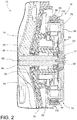
FIG. 2 is a cross-sectional view of an example of a direct drive motor that may be used in the laundry appliance ofFIG. 1 ; -
FIG. 3 is a perspective view of a rotor assembly used in the motor shown inFIG. 2 ; -
FIG. 4 is a cross-sectional view of the rotor assembly shown inFIG. 3 taken along line IV-IV; -
FIG. 5 is an enlarged cross-sectional view of a region of the rotor assembly shown inFIG. 4 designated as area V; -
FIG. 6 is an exploded perspective view of the rotor assembly shown inFIGS. 3-5 ; -
FIG. 7 is a schematic view of an apparatus for producing a metal strip used in the rotor assembly shown inFIGS. 3-6 ; -
FIG. 8A is a cross-sectional view of the apparatus shown inFIG. 7 taken along line VIIIA; -
FIG. 8B is a cross-sectional view of the apparatus shown inFIG. 7 taken along line VIIIB; -
FIG. 8C is a cross-sectional view of the apparatus shown inFIG. 7 taken along line VIIIC; -
FIG. 8D is a cross-sectional view of the apparatus shown inFIG. 7 taken along line VIIID; -
FIG. 8E is a cross-sectional view of the apparatus shown inFIG. 7 taken along line VIIIE; -
FIG. 9 is a perspective view of an apparatus for forming the yoke used in the rotor assembly shown inFIGS. 3-5 using the metal strip as formed using the apparatus shown inFIGS. 7-8E ; and -
FIG. 10 is an enlarged perspective view of the metal strip corresponding to the area X inFIG. 9 . - For purposes of description herein the terms "upper," "lower," "right," "left," "rear," "front," "vertical," "horizontal," and derivatives thereof shall relate to the device as oriented in
FIG. 1 . However, it is to be understood that the device may assume various alternative orientations and step sequences, except where expressly specified to the contrary. It is also to be understood that the specific devices and processes illustrated in the attached drawings and described in the following specification are simply exemplary embodiments of the inventive concepts defined in the appended claims. Hence, specific dimensions and other physical characteristics relating to the embodiments disclosed herein are not to be considered as limiting, unless the claims expressly state otherwise. - As indicated above, the embodiments described herein relate to a rotor assembly for use in a direct drive motor of a laundry appliance.
FIG. 1 shows alaundry appliance 10 that happens to be in the form of a washing appliance. In some embodiments, thelaundry appliance 10 may include additional and/or different components than those shown inFIG. 1 and described herein. The laundry appliance includes adrum 18 in which laundry is received. Thedrum 18 is disposed in atub 76 and is rotated by means of amotor 16 as described further below. - In the illustrative embodiment shown in
FIG. 1 , thelaundry appliance 10 is a front-loaded appliance in which thedrum 18 is accessed through an opening defined in the front of thelaundry appliance 10. It should be appreciated that in other embodiments thelaundry appliance 10 may have other configurations. For example, thelaundry appliance 10 may be a top-loaded appliance in which thedrum 18 is accessed through an opening defined in the top of thelaundry appliance 10. Further, in the illustrative embodiment, the rotational axis 62 (FIG. 2 ) of thedrum 18 is horizontal. It should be appreciated that the rotational axis may have other configurations; for example, the rotational axis may be vertical. Thelaundry appliance 10 may further include auser interface panel 30 for a user to control the wash/dry cycles of the appliance. - The
motor 16 may be a direct drive permanent magnet synchronous motor (also known as a brushless, alternating current (AC) motor). As shown inFIG. 2 , according to the various embodiments, amotor 16 for thelaundry appliance 10, such as a direct drive, may include adrive shaft 60 that is coupled to adrum 18 at afirst end 64 ofdrive shaft 60. Arotor assembly 74 having arotor frame 66 is coupled proximate asecond end 68 of thedrive shaft 60. Acentral hub 72 is included within therotor frame 66. - The
drum 18 includes a cavity that is sized to receive clothes and other laundry 20 to be washed or dried in thelaundry appliance 10. Thedrum 18 is set within atub 76 that receives wash water for cleaning the laundry set within thedrum 18. Thedirect drive motor 16 is attached proximate thetub 76, where astator assembly 78 of thedirect drive motor 16 is coupled to a portion of thetub 76, thereby substantially fixing the location of thestator assembly 78. Disposed in thetub 76 is a bearinghousing 80 including at least one bearing 82 that allows thedrive shaft 60 to be rotated within thewall 84 of thetub 76. As described further below, therotor assembly 74 includesmagnets 86 that are in magnetic communication withstator coils 88 of thestator assembly 78 and form a permanentsynchronous motor 16. Eachstator field coil 88 of themotor 16 is separately electrically connected to an inverter (not shown). During operation, the inverter supplies AC power of the same frequency but with different phases to eachstator field coil 88 of themotor 16. The multi-phased AC power flows through thestator field coils 88 of themotor 16 to produce a rotating magnetic field; that is, the direction of the combined magnetic field produced by the plurality ofstator field coils 88 rotates. This rotating magnetic field interacts with the one or morepermanent magnets 86 and causes therotor assembly 74 to rotate. In this manner, as therotor 74 rotates about thestator assembly 78, the connection of therotor assembly 74 to thedrum 18 via thedrive shaft 60 allows for the transfer of torque from therotor assembly 74 to thedrive shaft 60 and, in turn, to thedrum 18 such that thedrum 18,drive shaft 60, androtor assembly 74 rotate aboutrotation axis 62. Therotation axis 62 corresponds to "the axial direction" as used herein. Moreover, the term "the radial direction" refers to directions that are perpendicular torotation axis 62. - It is contemplated that other types of
electric motors 16 can be utilized where themotor 16 includes arotor assembly 74 that rotates relative to astator assembly 78.Such motors 16 can include, but are not limited to, direct drive motors, motors that are coupled to transmissions, belt-drive motors, and other similar electric motors. Additionally, the various aspects of the embodiments can be used in various orientations ofmotor 16, including motors that are positioned along a vertical axis, a horizontal axis and/or an angled axis. - As shown in
FIGS. 3-6 and described above, therotor assembly 74 includes thecentral hub 72 for securing the rotor assembly to thedrive shaft 60 of themotor 16 such that therotor assembly 74 rotates about theaxis 62 of thedrive shaft 60. As also described above, therotor assembly 74 further includes arotor frame 66 and a plurality ofmagnets 86. Therotor frame 66 includes ahub region 92 for receiving thecentral hub 72. Thehub region 92 extends radially outward from thecentral hub 72 and has a circular outer periphery. Aportion 94 ofhub region 92 may have a thinner profile than the portion surroundingcentral hub 72. Therotor frame 66 further includes acylindrical rim 96 extending axially from the outer periphery of thehub region 92 so as to be coaxial with therotational axis 62 of thedrive shaft 60. Thecylindrical rim 96 has an inner surface facing towards the cylindrical outer surface of thestator assembly 78. - The rotor assembly further includes a cylindrical yoke 100 (also known as a back iron) disposed adjacent the inner surface of the
cylindrical rim 96. Thecylindrical yoke 100 has an inner surface facing towards the cylindrical outer surface of thestator assembly 78. The plurality ofmagnets 86 are disposed adjacent the inner surface of thecylindrical yoke 100. As described further below, thecylindrical yoke 100 includes ametal strip 102 configured in the form of a helix. - As shown in
FIGS. 5 and10 , themetal strip 102 has a thickness T in the radial direction and a width W in the axial direction. The width ofmetal strip 102 may be less than the thickness. For example, the thickness of themetal strip 102 may be between about 3 mm and about 7 mm, and the width may be between about 0.5 mm and about 2 mm. Themetal strip 102 as configured in the form of a helix may be formed such that any air gaps between adjacent windings of themetal strip 102 are between about 2 µm and about 10 µm. This may be accomplished by winding the metal strip around acylindrical mandrel 110 as shown inFIG. 9 , while usingmember 112 to guide themetal strip 102 onto themandrel 110 so as to obtain the appropriate spacing relative to the last winding applied to themandrel 110. Note thatmember 112 may be forked such themetal strip 102 is guided between to prongs of the forked end ofmember 112. Themandrel 110 may have aradially protruding flange 114 at one or both ends in order to press the first winding of themetal strip 102 against theflange 114. -
Helical yoke 100 may have an axial height H (FIG. 6 ) of about 20 mm to about 70 mm and a radial thickness of about 0.5 mm to about 2 mm. The radial thickness corresponds to the thickness of themetal strip 102. If the metal strip has a thickness of 0.5 mm and a yoke with an axial height of 30 mm was desired, for example, themetal strip 102 would include approximately 60 windings with no air gaps between the windings. The height and thickness ofyoke 100 are flexible to accommodate the magnetic flux density as requested by the application. To help assure the stiffness and alignment while the layers are stacked, some fixation features may be added. For example, rivet pins may be added on the yoke to provide welding lines on the outer face of the yoke. Another option would be to apply some adhesive bond. In general, however, the bonding among the back iron, magnets and therotor frame 66 is done by a polymeric over-molding process to contribute to the desired stiffness of therotor assembly 74. - One example of a method for making
rotor assembly 74 includes forming ahelical yoke 100 using ametal strip 102, theyoke 100 having an outer surface and an inner surface; disposingmagnets 86 about an outer surface of an insert mold; positioning thehelical yoke 100 around themagnets 86 such that the inner surface of thehelical yoke 100 faces themagnets 86; placing the insert mold with themagnets 86 and thehelical yoke 100 into an injection mold cavity; and injection molding aplastic rotor frame 66 where therotor frame 66 has acylindrical rim 96 that extends along the outer surface of thehelical yoke 100. - As mentioned above, the
yoke 100 may be pre-formed by winding themetal strip 102 around a mandrel and then slid axially over the outer surfaces of themagnets 86. In a variation of the above method, the yoke may be formed by winding the metal strip around themagnets 86 themselves instead of a mandrel. As yet another variation, therotor frame 66 may be pre-formed and theyoke 100 andmagnets 86 may be press-fit into therim 96 offrame 66. - The
magnets 86 may be made of any conventional magnetic material and may be provided in various forms including in a magnet chain as described in U.S. Patent Application Publication No.US 2015/0089794 A1 . - The
metal strip 102 may be made of any ferromagnetic steel or other metal known to be suitable for use as a yoke. A method of forming themetal strip 102 is described below with reference toFIGS. 7 and 8A-8E . - The
metal strip 102 may be made by various methods. One method is to simply cut a plurality of metal strips from a large sheet of metal using an industrial slitting apparatus. Such an apparatus can provide metal strips of and dimension down to about 9 mm when cutting a sheet of about 0.5 mm to 2 mm thickness. However, in order to obtain metal strips with a dimension of less than 9 mm, the method shown in toFIGS. 7 and 8A-8E may be used. - As shown in
FIG. 7 , a steel rod having a substantially circular cross-section (as shown inFIG. 8A ) is fed through a first set of pressingrollers FIG. 8B . Then the steel is fed through successive second, third, and fourth sets of pressingrollers 120c-120h where the steel is further flattened to a thinner profile as shown inFIGS. 8C-8E , until the desired dimensions of themetal strip 102 are obtained. It will be appreciated that fewer or greater sets of rollers may be used to obtain the desired cross-sectional shape. As noted above, the metal strip may have a thickness (the horizontal dimension inFIG. 8E ) of about 3 mm to about 7 mm and a width (the vertical dimension inFIG. 8E ) of about 0.5 mm to about 2 mm. The cross-sectional area of the starting steel rod will correspond to the desired cross-sectional area of the metal strip. - An annealing step may be performed on the
metal strip 102 to provide the steel the desired properties. Once themetal strip 102 is formed, thehelical yoke 100 is created by bending thisstrip 102 with its rectangular cross section on direction of its width (not in the thickness direction) on a mandrel or the like as discussed above. The strip will thus be bent and wound into the desired diameter of the yoke. Some welding may be performed around the external surface of the finalhelical yoke 100. One may then conform the external diameter by fitting thehelical yoke 100 inside a template. - The above-described
rotor assembly 74 satisfies several design goals. First, it allows for consistent spacing between the outer diameter of thestator assembly 78 and the inner diameter of therotor assembly 74. This is accomplished by ensuring circularity of therotor assembly 74 and thestator assembly 78, ensuring therotor assembly 74 has sufficient radial mechanical stiffness and rigidity to avoid distortion of its circularity while rotating, and reducing vibration of therotor assembly 74. Compared to yokes made of joined arc segments, thehelical yoke 100 has better circularity. Second, therotor assembly 74 reduces noise by having improved radial stiffness and by reducing vibration. Third, by providing consistent spacing between the outer diameter of thestator assembly 78 and the inner diameter of therotor assembly 74, the electromagnetic performance is improved and hence the efficiency of themotor 16 is improved. Also, the cost of producing the motor may be lowered and temperature management may be improved. The cost is lowered by using less material as compared to yokes made of joined arc segments and by having lower run out variation. - It will be understood by one having ordinary skill in the art that construction of the described device and other components is not limited to any specific material. Other exemplary embodiments of the device disclosed herein may be formed from a wide variety of materials, unless described otherwise herein.
- For purposes of this disclosure, the term "coupled" (in all of its forms, couple, coupling, coupled, etc.) generally means the joining of two components (electrical or mechanical) directly or indirectly to one another. Such joining may be stationary in nature or movable in nature. Such joining may be achieved with the two components (electrical or mechanical) and any additional intermediate members being integrally formed as a single unitary body with one another or with the two components. Such joining may be permanent in nature or may be removable or releasable in nature unless otherwise stated.
- It is also important to note that the construction and arrangement of the elements of the device as shown in the exemplary embodiments is illustrative only. Although only a few embodiments of the present innovations have been described in detail in this disclosure, those skilled in the art who review this disclosure will readily appreciate that many modifications are possible (e.g., variations in sizes, dimensions, structures, shapes and proportions of the various elements, values of parameters, mounting arrangements, use of materials, colors, orientations, etc.) without materially departing from the teachings and advantages of the subject matter recited. For example, elements shown as integrally formed may be constructed of multiple parts or elements shown as multiple parts may be integrally formed, the operation of the interfaces may be reversed or otherwise varied, the length or width of the structures and/or members or connector or other elements of the system may be varied, the nature or number of adjustment positions provided between the elements may be varied. It should be noted that the elements and/or assemblies of the system may be constructed from any of a wide variety of materials that provide sufficient strength or durability in any of a wide variety of colors, textures, and combinations. Accordingly, all such modifications are intended to be included within the scope of the present innovations. Other substitutions, modifications, changes, and omissions may be made in the design, operating conditions, and arrangement of the desired and other exemplary embodiments without departing from the spirit of the present innovations.
- It will be understood that any described processes or steps within described processes may be combined with other disclosed processes or steps to form structures within the scope of the present device. The exemplary structures and processes disclosed herein are for illustrative purposes and are not to be construed as limiting.
- It is also to be understood that variations and modifications can be made on the aforementioned structures and methods without departing from the concepts of the present device, and further it is to be understood that such concepts are intended to be covered by the following claims unless these claims by their language expressly state otherwise.
- The above description is considered that of the illustrated embodiments only. Modifications of the device will occur to those skilled in the art and to those who make or use the device. Therefore, it is understood that the embodiments shown in the drawings and described above is merely for illustrative purposes and not intended to limit the scope of the device, which is defined by the following claims as interpreted according to the principles of patent law.
Claims (15)
- A rotor assembly (74) for a motor (16) of a laundry appliance (10), the motor (16) having a stator assembly (78) having an outer surface about which the rotor assembly (74) rotates, the rotor assembly (74) comprising:a central hub (72) for securing the rotor assembly (74) to a drive shaft (60) of the motor (16) such that the rotor assembly (74) rotates about an axis of the drive shaft (60);a rotor frame (66) comprising:a hub region (92) for receiving the central hub (72), the hub region (92) extending radially outward from the central hub (72) and having a circular outer periphery, anda cylindrical rim (96) extending axially from the outer periphery of the hub region (92) so as to be coaxial with the drive shaft (60), the cylindrical rim (96) having an inner surface facing towards the outer surface of the stator assembly (78);a yoke (100) disposed at the inner surface of the cylindrical rim (96), the yoke (100) having an inner surface facing towards the outer surface of the stator assembly (78); anda plurality of magnets (86) disposed at the inner surface of the yoke (100),wherein the yoke comprises a helically wound metal strip (102).
- The rotor assembly (74) of claim 1, wherein the metal strip (102) has a thickness in the radial direction and has a width in the axial direction that is less than the thickness in the radial direction.
- The rotor assembly (74) of claim 2, wherein the thickness of the metal strip (102) is between about 3 mm and about 7 mm.
- The rotor assembly (74) of any one of claims 2 and 3, wherein the width of the metal strip (102) is between about 0.5 mm and about 2 mm.
- The rotor assembly (74) of any one of claims 1-4, wherein the rotor frame (66) is injection-molded to form the rim around an outer surface of the yoke (100).
- The rotor assembly (74) of any one of claims 1-5, wherein the helically wound metal strip is formed such that any air gaps between adjacent windings of the metal strip are between about 2 µm and about 10 µm.
- A laundry appliance (10) comprising:a drum (18) for receiving laundry; anda motor (16) for rotating the drum (18), wherein the motor (16) comprises a stator assembly (78) and the rotor assembly (74) of any one of claims 1-6.
- A motor (16) comprising the rotor assembly of any one of claims 1-6 and a stator assembly (78) having an outer surface about which the rotor assembly rotates (74).
- A laundry appliance (10) comprising:a drum (18) for receiving laundry; andthe motor (16) of claim 8 for rotating the drum (18).
- A method of making a rotor assembly (74) comprising:forming a yoke (100) using a helically wound metal strip (102), the yoke (100) having an outer surface and an inner surface;disposing magnets (86) about an outer surface of an insert mold;positioning the yoke (100) around the magnets (86) such that the inner surface of the yoke (100) faces the magnets (86);placing the insert mold with the magnets (86) and the yoke (100) into an injection mold cavity; andinjection molding a rotor frame (66) where the rotor frame has a cylindrical rim (96) that extends along the outer surface of the yoke (100).
- The method of claim 10, wherein the step of forming the yoke (100) includes helically winding the metal strip (102) around a mandrel (110) and removing the metal strip (102) from the mandrel (110).
- The method of claim 11, wherein, in the step of forming the yoke (100), the metal strip (102) is guided onto the mandrel (110) such that any air gaps between adjacent windings of the metal strip (102) are between about 2 µm and about 10 µm.
- The method of any one of claims 10-12, wherein the metal strip (102) has a thickness in the radial direction and has a width in the axial direction that is less than the thickness in the radial direction.
- The method of any one of claim 13, wherein the thickness of the metal strip (102) is between about 3 mm and about 7 mm.
- The method of any one of claims 13 and 14, wherein the width of the metal strip (102) is between about 0.5 mm and about 2 mm.
Applications Claiming Priority (1)
| Application Number | Priority Date | Filing Date | Title |
|---|---|---|---|
| US15/139,624 US20170317539A1 (en) | 2016-04-27 | 2016-04-27 | Rotor assembly for a direct drive motor |
Publications (1)
| Publication Number | Publication Date |
|---|---|
| EP3244512A1 true EP3244512A1 (en) | 2017-11-15 |
Family
ID=58192216
Family Applications (1)
| Application Number | Title | Priority Date | Filing Date |
|---|---|---|---|
| EP17158575.5A Withdrawn EP3244512A1 (en) | 2016-04-27 | 2017-02-28 | Rotor assembly for a direct drive motor |
Country Status (2)
| Country | Link |
|---|---|
| US (1) | US20170317539A1 (en) |
| EP (1) | EP3244512A1 (en) |
Families Citing this family (3)
| Publication number | Priority date | Publication date | Assignee | Title |
|---|---|---|---|---|
| US11777350B2 (en) | 2018-10-04 | 2023-10-03 | ZF Active Safety US Inc. | Integrated rotor |
| US11114915B2 (en) | 2018-10-04 | 2021-09-07 | ZF Active Safety US Inc. | Integrated rotor yoke |
| JP7641765B2 (en) * | 2021-02-26 | 2025-03-07 | ミネベアミツミ株式会社 | Motor |
Citations (5)
| Publication number | Priority date | Publication date | Assignee | Title |
|---|---|---|---|---|
| JP2000152524A (en) * | 1998-11-17 | 2000-05-30 | Nippon Keiki Seisakusho:Kk | Structure of rotor-side yoke for motor |
| DE102006015037A1 (en) * | 2006-03-31 | 2007-10-11 | Siemens Ag | Rotor of a permanent magnet synchronous machine |
| WO2011162624A1 (en) * | 2010-06-25 | 2011-12-29 | Fisher & Paykel Appliances Limited | A rotor for a motor, and a motor and an appliance comprising the rotor, and a method for making a rotor |
| US20120091852A1 (en) * | 2009-03-19 | 2012-04-19 | Robert Bosch Gmbh | Electrical machine |
| US20150089794A1 (en) | 2013-10-01 | 2015-04-02 | Whirlpool Corporation | Method of manufacturing a rotor for an electric motor for a washing machine |
-
2016
- 2016-04-27 US US15/139,624 patent/US20170317539A1/en not_active Abandoned
-
2017
- 2017-02-28 EP EP17158575.5A patent/EP3244512A1/en not_active Withdrawn
Patent Citations (5)
| Publication number | Priority date | Publication date | Assignee | Title |
|---|---|---|---|---|
| JP2000152524A (en) * | 1998-11-17 | 2000-05-30 | Nippon Keiki Seisakusho:Kk | Structure of rotor-side yoke for motor |
| DE102006015037A1 (en) * | 2006-03-31 | 2007-10-11 | Siemens Ag | Rotor of a permanent magnet synchronous machine |
| US20120091852A1 (en) * | 2009-03-19 | 2012-04-19 | Robert Bosch Gmbh | Electrical machine |
| WO2011162624A1 (en) * | 2010-06-25 | 2011-12-29 | Fisher & Paykel Appliances Limited | A rotor for a motor, and a motor and an appliance comprising the rotor, and a method for making a rotor |
| US20150089794A1 (en) | 2013-10-01 | 2015-04-02 | Whirlpool Corporation | Method of manufacturing a rotor for an electric motor for a washing machine |
Also Published As
| Publication number | Publication date |
|---|---|
| US20170317539A1 (en) | 2017-11-02 |
Similar Documents
| Publication | Publication Date | Title |
|---|---|---|
| US9013086B2 (en) | Stator for an electric motor including separately formed end pieces and associated method | |
| EP1842278B1 (en) | Double rotor type motor | |
| US9806581B2 (en) | Rotor for a motor, and a motor and an appliance comprising the rotor, and a method for making a rotor | |
| US8941274B2 (en) | Stator for an electric motor of a washing machine and method of manufacturing the same | |
| US9255354B2 (en) | Washing machine to produce three-dimensional motion | |
| US20080122300A1 (en) | Motor | |
| EP0361775A2 (en) | Improvements in or relating to machine drives and/or methods of making the same | |
| KR20160094329A (en) | Electric motor | |
| US20100038985A1 (en) | Brushless dc motor, magnetizing method thereof and washing machine having the same | |
| EP1737105A2 (en) | Rotor of motor and manufacturing method thereof | |
| US6954018B2 (en) | Rotor of line start permanent magnet motor and manufacturing method thereof | |
| US20170317539A1 (en) | Rotor assembly for a direct drive motor | |
| CN218514264U (en) | Axial flux motor for washing machine | |
| CN102255403B (en) | Manufacturing process of brushless motor with iron-core-free disc winding and axial magnetic field | |
| JP2009077603A (en) | Electric motor | |
| CN101632213A (en) | Double rotor type motor | |
| US20140084746A1 (en) | Dc commutator motor and auxiliary machine for motor vehicle using the same | |
| CN203660715U (en) | Motor and permanent magnet motor | |
| JP2015198500A (en) | Permanent magnet type motor | |
| KR101031615B1 (en) | Rotor bracket and rotor bushing structure of outer rotor type motor | |
| KR101405963B1 (en) | motor | |
| CN119231785A (en) | Stator of axial flux motor, axial flux motor and wind wheel assembly | |
| US20220302772A1 (en) | Electric motor for an appliance | |
| KR101397047B1 (en) | motor | |
| JP2016034176A (en) | Rotor |
Legal Events
| Date | Code | Title | Description |
|---|---|---|---|
| PUAI | Public reference made under article 153(3) epc to a published international application that has entered the european phase |
Free format text: ORIGINAL CODE: 0009012 |
|
| STAA | Information on the status of an ep patent application or granted ep patent |
Free format text: STATUS: THE APPLICATION HAS BEEN PUBLISHED |
|
| AK | Designated contracting states |
Kind code of ref document: A1 Designated state(s): AL AT BE BG CH CY CZ DE DK EE ES FI FR GB GR HR HU IE IS IT LI LT LU LV MC MK MT NL NO PL PT RO RS SE SI SK SM TR |
|
| AX | Request for extension of the european patent |
Extension state: BA ME |
|
| STAA | Information on the status of an ep patent application or granted ep patent |
Free format text: STATUS: THE APPLICATION IS DEEMED TO BE WITHDRAWN |
|
| 18D | Application deemed to be withdrawn |
Effective date: 20180516 |