EP3244246A1 - Camera module for a motor vehicle - Google Patents
Camera module for a motor vehicle Download PDFInfo
- Publication number
- EP3244246A1 EP3244246A1 EP16169093.8A EP16169093A EP3244246A1 EP 3244246 A1 EP3244246 A1 EP 3244246A1 EP 16169093 A EP16169093 A EP 16169093A EP 3244246 A1 EP3244246 A1 EP 3244246A1
- Authority
- EP
- European Patent Office
- Prior art keywords
- camera module
- material element
- back plate
- lens
- layers
- Prior art date
- Legal status (The legal status is an assumption and is not a legal conclusion. Google has not performed a legal analysis and makes no representation as to the accuracy of the status listed.)
- Granted
Links
Images
Classifications
-
- G—PHYSICS
- G02—OPTICS
- G02B—OPTICAL ELEMENTS, SYSTEMS OR APPARATUS
- G02B7/00—Mountings, adjusting means, or light-tight connections, for optical elements
- G02B7/008—Mountings, adjusting means, or light-tight connections, for optical elements with means for compensating for changes in temperature or for controlling the temperature; thermal stabilisation
-
- H—ELECTRICITY
- H04—ELECTRIC COMMUNICATION TECHNIQUE
- H04N—PICTORIAL COMMUNICATION, e.g. TELEVISION
- H04N23/00—Cameras or camera modules comprising electronic image sensors; Control thereof
- H04N23/50—Constructional details
- H04N23/52—Elements optimising image sensor operation, e.g. for electromagnetic interference [EMI] protection or temperature control by heat transfer or cooling elements
-
- G—PHYSICS
- G02—OPTICS
- G02B—OPTICAL ELEMENTS, SYSTEMS OR APPARATUS
- G02B7/00—Mountings, adjusting means, or light-tight connections, for optical elements
- G02B7/02—Mountings, adjusting means, or light-tight connections, for optical elements for lenses
- G02B7/028—Mountings, adjusting means, or light-tight connections, for optical elements for lenses with means for compensating for changes in temperature or for controlling the temperature; thermal stabilisation
-
- H—ELECTRICITY
- H04—ELECTRIC COMMUNICATION TECHNIQUE
- H04N—PICTORIAL COMMUNICATION, e.g. TELEVISION
- H04N23/00—Cameras or camera modules comprising electronic image sensors; Control thereof
- H04N23/50—Constructional details
- H04N23/54—Mounting of pick-up tubes, electronic image sensors, deviation or focusing coils
-
- H—ELECTRICITY
- H04—ELECTRIC COMMUNICATION TECHNIQUE
- H04N—PICTORIAL COMMUNICATION, e.g. TELEVISION
- H04N23/00—Cameras or camera modules comprising electronic image sensors; Control thereof
- H04N23/50—Constructional details
- H04N23/55—Optical parts specially adapted for electronic image sensors; Mounting thereof
-
- B—PERFORMING OPERATIONS; TRANSPORTING
- B60—VEHICLES IN GENERAL
- B60Q—ARRANGEMENT OF SIGNALLING OR LIGHTING DEVICES, THE MOUNTING OR SUPPORTING THEREOF OR CIRCUITS THEREFOR, FOR VEHICLES IN GENERAL
- B60Q9/00—Arrangement or adaptation of signal devices not provided for in one of main groups B60Q1/00 - B60Q7/00, e.g. haptic signalling
- B60Q9/008—Arrangement or adaptation of signal devices not provided for in one of main groups B60Q1/00 - B60Q7/00, e.g. haptic signalling for anti-collision purposes
Definitions
- the invention relates to a camera module for a motor vehicle, comprising a lens objective, a housing comprising a back plate and a lens holder, wherein said back plate carries an image sensor within the housing, wherein said lens holder is mounted to said back plate and holds said lens objective such that said image sensor is arranged in or close to an image plane of the lens objective.
- Automotive camera modules are exposed to temperatures varying over a large range, and are required to have excellent imaging performance over the whole temperature range occurring in practice. Furthermore, automotive camera modules normally do not include an autofocusing mechanism for cost reasons. In many fixed-focus automotive camera modules, a major challenge is to retain the focus over the temperature envelope T. For low f/# lenses, the distance between the image and the sensor must be controlled at a scale of micrometres.
- WO 2015/032512 A1 discloses an automotive camera module having a tube holding the lens objective, the tube being tuned to cancel the image plane drift. Although this solution is simple and reliable, the tube is an additional part which causes additional steps in the mounting of the camera module.
- the problem underlying the present invention is to provide a fast-to-mount camera module having a simple mechanism to keep the image sensor close to the image plane of the lens objective.
- the invention solves this objective with the features of the independent claims.
- the invention has realized that the thermal drift of the focus plane out of the image sensor plane can be counteracted at the back side of the camera module, namely by providing a bi-material element holding the image sensor and designed to bend with changing temperature.
- the bending action causes the image sensor to move, and this movement can be designed such that the image sensor, and with it the sensor plane, follows the thermal displacement of the image focus plane.
- the bi-material element is designed such that the bending of the bi-material element acts towards keeping the image plane in a predetermined positional relation to the image sensor, most preferably in the sensitive plane of the image sensor.
- the bending of the bi-material element holding the image sensor is tuned such that the image focus plane and the sensor plane are coinciding over the whole temperature range existing in automotive applications.
- the bi-material element is designed such that a thermal displacement of the bi-material element is able to compensate a thermal expansion of the lens holder and a shift of the image plane caused by changes of and within the lens objective.
- the designing of the bi-material element comprises one or more of:
- the material of one or preferably both of said at least two layers is a metal.
- the bi-material element may be a bi-metal strip or plate.
- the material of the layers may for example be based on iron, like steel, and/or be based on copper and/or tin, like brass.
- the layers are formed by layers of a sandwiched structure, like a PCB structure, comprising a metal layer, for example a copper layer, and a non-metal composite layer, like a glass fibre layer.
- a metal layer for example a copper layer
- a non-metal composite layer like a glass fibre layer.
- the bending properties of the plate may preferably be tuned by one or more of
- the invention solves the above mentioned objective also with a camera module of the same kind, where instead of a bi-material element in the back plate, the back plate and the lens holder are made of materials having thermal properties and geometries and being connected together such that the back plate is adapted to bend with changing temperature.
- the material, thickness and geometries of the back plate and the lens holder are combined to achieve the bi-material effect.
- Many preferred features described above with respect to the bi-material element in the back plate also apply for this embodiment in a corresponding manner.
- the back plate is designed and connected to the lens holder in such a manner such that the bending of the back plate acts towards keeping the image plane in a predetermined positional relation to the image sensor.
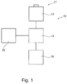
- a vision system 10 which is mounted in a motor vehicle (not shown) and comprises an imaging apparatus 11 for acquiring images of a region surrounding the motor vehicle, for example a region in front of the motor vehicle.
- the imaging apparatus 11 comprises one or more camera modules 12.
- the camera module 12 preferably operates in the visible wavelength region.
- the camera module 12 operates in the infrared wavelength region, where infrared covers near IR with wavelengths below 5 microns and/or far IR with wavelengths beyond 5 microns.
- the imaging apparatus 11 comprises a plurality of camera modules 12 in particular forming a stereo imaging apparatus 11. Alternatively only camera module 12 forming a mono imaging apparatus 11 can be used.
- the image data from the imaging apparatus 11 are provided to an electronic processing device 14 where image and data processing is carried out by corresponding software.
- the image and data processing in the processing device 14 comprises the following functions: identification and classification of possible objects surrounding the motor vehicle, such as pedestrians, other vehicles, bicyclists or large animals; tracking over time the position of identified object candidates in the recorded images; calculation of a collision probability between the vehicle and a detected object; and/or activation or control of at least one driver assistance device 18 depending on the result of the object detection and tracking processing and/or said collision probability calculation.
- the driver assistance device 18 may comprise a display device for displaying information relating to a detected object; a warning device adapted to provide a collision warning to the driver by suitable optical, acoustical and/or haptical warning signals; one or more restraint systems such as occupant airbags or safety belt tensioners, pedestrian airbags, hood lifters and the like; and/or dynamic vehicle control systems such as brakes or steering device.
- the processing device 14 expediently has access to a memory device 25.
- the data processing device 14 is preferably a digital device which is programmed or programmable and preferably comprises a microprocessor, micro-controller, digital signal processor (DSP) or a System-On-Chip (SoC) device.
- the data processing device 14 and the memory device 25 are preferably realised in an on-board electronic control unit (ECU) and may be connected to the imaging apparatus 11 via a separate cable or a vehicle data bus.
- ECU electronice control unit
- the ECU and one or more of the imaging devices 12 can be integrated into a single unit, where a one box solution including the ECU and all imaging devices 12 can be preferred. All steps from imaging, image processing to possible activation or control of driver assistance device 18 are performed automatically and continuously during driving in real time.
- the camera module 12 comprises a lens objective 20, a housing 22 and an image sensor 24.
- the housing 22 comprises a lens holder 53 and a back plate 32 holding the image sensor 24.
- the housing 22 is basically closed in a light tight manner except for an opening 28 at a front end.
- the lens holder 53 comprises a tubular part 54 holding the lens objective 20 and a base part 55 adapted to connect the lens holder 53 to the back plate 32.
- the tubular part 54 is preferably cylindrical and extends parallel to the optical axis of the lens objective 20.
- the lens objective 20 focuses the image in the image plane A of the lens objective 20.
- the lens objective 20 and the sensitive plane of the image sensor 24 are arranged apart from each other with a predetermined distance d1, which ideally corresponds to the back focal distance of the lens objective 20 such that the image focus lies in the sensitive plane of the image sensor 24.
- the image sensor 24 is preferably a two-dimensional image sensor, in particular an optical sensor having maximum sensitivity preferably in the visible wavelength region, and is adapted to convert incident light into an electrical signal containing image information of the image to be detected.
- the image sensor 24 is advantageously arranged within the housing 22 in or close to the image plane A of the lens objective 20.
- the lens holder 53 is made of a metal or a metal alloy, for example a zink alloy.
- the lens holder 53 may be made of a polymer material, for example Polyphenylene sulphide (PPS).
- PPS Polyphenylene sulphide
- the lens holder 53 is made of reinforced plastics, in particular glass fiber and/or mineral powder reinforced plastics.
- a very preferred material for the lens holder 53 is PPS GM65, i.e. PPS with 65% glass fiber and mineral powder reinforcement.
- the temperature dependent distance a(T) between the image plane A and the sensitive surface of the sensor 24 is determined by two parameters, see Figure 2 .
- the first is the temperature dependent distance d1(T) between the lens objective 20 and the sensitive surface of the sensor 24.
- the second is the distance d2(T) between the lens objective 20 and the image plane A which varies over temperature due to mechanical displacements in the lens objective 20, change in refractive index of the optical elements or lenses in the lens objective 20, dimensional changes within the lens objective 20, etc.
- the image sensor 24 is mounted on a bi-material element 31 which is preferably planar and has the form of a plate or strip.
- the bi-material element 31 can form the back plate 32, be part of the back plate 32 or be mounted on the back plate 32.
- the image sensor 24 is preferably mounted in the center of the bi-material element 31 in a longitudinal direction, as shown in Figures 2 to 4 .
- the bi-material element 31 comprises at least two layers 33, 34 made of different materials having significantly different coefficients of thermal expansion (CTE) and connected to each other in a manner (for example along opposing edges of the bi-material element 31) such that the bi-material element 31 bends which changing temperature.
- CTE coefficients of thermal expansion
- the layers 33, 34 may be made of metal, for example an iron based layer 33 like steel, and a copper and/or tin based layer 34 like brass.
- the layers 33, 34 may be the layers of a sandwiched PCB structure, in particular a copper layer and a glass fiber layer.
- the plate 33 of material having the lower CTE is facing towards the lens objective 20 and carries the image sensor 24, whereas the plate 34 of material having the higher CTE is arranged at the outer side of the camera module 23 facing away from the lens objective 20.
- the bi-material element 31 bends outwards in a convex manner, i.e. away from the lens objective 20, with rising temperature.
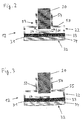
- Figure 2 shows a planar state of the bi-material element 31 at a reference temperature
- Figure 3 shows a bent state of the bi-material element 31 at a temperature significantly higher than the reference temperature. Since the lens holder 53 expands with rising temperature (no materials are known which contract with rising temperature), this embodiment may be beneficial in case where downward movement of the image plane A with rising temperature caused by effects in the lens objective 20 dominates over contraction of the lens holder 53.
- the plate 33 of material having the lower CTE is arranged at the outer side of the camera module 23 facing away from the lens objective 20, whereas the plate 34 of material having the higher CTE is facing towards the lens objective 20 and carries the image sensor 24.
- the arrangement of the layers 33, 34 is vice versa as compared to Figures 2 and 3 .
- the bi-material element 31 bends inwards in a concave manner, i.e. towards the lens objective 20, with rising temperature.
- This embodiment may be beneficial in case the expansion of the lens holder 53 is dominating over the movement of the image plane A caused by effects in the lens objective 20.
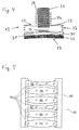
- the lens objective 20 comprises a lens barrel 63 and one or more lenses 64 to 69 held inside the lens barrel 63 and spaced from each other using ring shaped spacers 70, see Figure 5 .
- the lens barrel 63 and the spacers 70 are preferably made of metal, in particular brass.
- the lenses 64 to 69 may comprise convex lenses 65, 66, 68, 69 and concave lenses 64, 67.
- the outer shape of the lens barrel 63 is generally cylindrical and closely fits the inner cylindrical shape of the tubular part 24 such that the lens objective 20 is closely guided in the tubular part 24.
- a practical embodiment of the invention comprises a state with plane or even bi-material element 31 as shown in Figure 2 .
- a practical embodiment of the invention may be designed such that the bi-material element 31 changes between a less convex bent state and largely convex bent state, or between a less concave bent state and largely concave bent state. That is, the bi-material element 31 may be bent in one direction over the whole temperature range occurring in automobile operation.
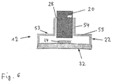
- Figure 6 shows an embodiment where the back plate 32 is made of a material, form and thickness which leads to a bending of the back plate 32 here towards the lens objective 20 when the temperature rises, such that the image sensor 24 mounted on the back plate 32 moves towards the lens objective 20 with rising temperature.
- the back plate 32 may be made of a material having significantly different thermal properties, in particular a higher CTE, as compared to the material of the lens holder 53. Therefore, in this embodiment, the desired bi-material effect is achieved through the connection of the back plate 32 to the lens holder 53, whereas no thermal bending is required in the back plate 32 on its own, i.e. when disconnected from the lens holder 53.
Landscapes
- Physics & Mathematics (AREA)
- General Physics & Mathematics (AREA)
- Optics & Photonics (AREA)
- Engineering & Computer Science (AREA)
- Multimedia (AREA)
- Signal Processing (AREA)
- Electromagnetism (AREA)
- Studio Devices (AREA)
- Lens Barrels (AREA)
Abstract
Description
- The invention relates to a camera module for a motor vehicle, comprising a lens objective, a housing comprising a back plate and a lens holder, wherein said back plate carries an image sensor within the housing, wherein said lens holder is mounted to said back plate and holds said lens objective such that said image sensor is arranged in or close to an image plane of the lens objective.
- Automotive camera modules are exposed to temperatures varying over a large range, and are required to have excellent imaging performance over the whole temperature range occurring in practice. Furthermore, automotive camera modules normally do not include an autofocusing mechanism for cost reasons. In many fixed-focus automotive camera modules, a major challenge is to retain the focus over the temperature envelope T. For low f/# lenses, the distance between the image and the sensor must be controlled at a scale of micrometres.
- Temperature differences lead to a respective change of the dimensions of the housing of the camera module. For instance, the height of the housing increases due to thermal expansion with an increase of the housing temperature. Accordingly, a distance between the lens objective, usually attached to a front end of the housing, and the image sensor, usually arranged at a back end of the housing, increases with a temperature increase, resulting in the sensor moving out of the image plane of the lens objective. Consequently, at high or very low temperatures the image sensor may not detect an image as clear as at moderate temperatures.
- Therefore, for fixed focus cameras, there is a need to balance the image plane drift caused by the lens objective at largely varying temperatures; otherwise image sharpness will inevitably decrease under such conditions. Even more, since pixel size of image sensors is constantly being reduced, the image plane drift has to be controlled with increasing precision.
- Solutions exist to control the image plane drift by introducing counter-acting mechanical elements in the camera module, so-called "athermalizers". For example,
WO 2015/032512 A1 discloses an automotive camera module having a tube holding the lens objective, the tube being tuned to cancel the image plane drift. Although this solution is simple and reliable, the tube is an additional part which causes additional steps in the mounting of the camera module. - The problem underlying the present invention is to provide a fast-to-mount camera module having a simple mechanism to keep the image sensor close to the image plane of the lens objective.
- The invention solves this objective with the features of the independent claims. The invention has realized that the thermal drift of the focus plane out of the image sensor plane can be counteracted at the back side of the camera module, namely by providing a bi-material element holding the image sensor and designed to bend with changing temperature. The bending action causes the image sensor to move, and this movement can be designed such that the image sensor, and with it the sensor plane, follows the thermal displacement of the image focus plane.
- Preferably, therefore, the bi-material element is designed such that the bending of the bi-material element acts towards keeping the image plane in a predetermined positional relation to the image sensor, most preferably in the sensitive plane of the image sensor. Ideally the bending of the bi-material element holding the image sensor is tuned such that the image focus plane and the sensor plane are coinciding over the whole temperature range existing in automotive applications. Advantageously the bi-material element is designed such that a thermal displacement of the bi-material element is able to compensate a thermal expansion of the lens holder and a shift of the image plane caused by changes of and within the lens objective.
- The realization of the invention comprises different preferred aspects which shall be described in the following. Preferably the designing of the bi-material element comprises one or more of:
- choosing the material of the layers to have different suited coefficients of thermal expansion;
- choosing the material of the layers to have suited elastic moduli; and/or
- choosing a suited geometry of the bi-material element, in particular a suited thickness of the layers.
- In preferred embodiments under the present invention, the material of one or preferably both of said at least two layers is a metal. In particular, the bi-material element may be a bi-metal strip or plate. In these embodiments, the material of the layers may for example be based on iron, like steel, and/or be based on copper and/or tin, like brass.
- In other preferred embodiments under the present invention, the layers are formed by layers of a sandwiched structure, like a PCB structure, comprising a metal layer, for example a copper layer, and a non-metal composite layer, like a glass fibre layer. In such embodiments, the bending properties of the plate may preferably be tuned by one or more of
- - adjusting the copper coverage in the copper layer of the sandwiched structure, for example in the form of a square grid;
- - providing slits in at least one of said plate layers to mechanically decouple from the stiff lens holder;
- - providing an inhomogeneous pattern in said metal layer, in particular in said copper layer, wherein the inhomogeneous pattern may preferably comprise stripes in a preferred direction, a circular pattern, or combinations thereof.
- The invention solves the above mentioned objective also with a camera module of the same kind, where instead of a bi-material element in the back plate, the back plate and the lens holder are made of materials having thermal properties and geometries and being connected together such that the back plate is adapted to bend with changing temperature. In this embodiment, the material, thickness and geometries of the back plate and the lens holder are combined to achieve the bi-material effect. Many preferred features described above with respect to the bi-material element in the back plate also apply for this embodiment in a corresponding manner. In particular, the back plate is designed and connected to the lens holder in such a manner such that the bending of the back plate acts towards keeping the image plane in a predetermined positional relation to the image sensor.
- In the following the invention shall be illustrated on the basis of preferred embodiments with reference to the accompanying drawings, wherein:
- Fig. 1
- schematically shows a vision system comprising the inventive camera module;
- Figs. 2, 3
- schematically show an embodiment of the inventive camera module;
- Fig. 4
- schematically shows an inventive camera module in another embodiment;
- Fig. 5
- shows a schematic cross-sectional view of a lens objective for use in an inventive camera module; and
- Fig. 6
- schematically shows an inventive camera module in a further embodiment.
- In
Fig. 1 avision system 10 is shown which is mounted in a motor vehicle (not shown) and comprises animaging apparatus 11 for acquiring images of a region surrounding the motor vehicle, for example a region in front of the motor vehicle. Theimaging apparatus 11 comprises one ormore camera modules 12. Thecamera module 12 preferably operates in the visible wavelength region. In an alternative embodiment, thecamera module 12 operates in the infrared wavelength region, where infrared covers near IR with wavelengths below 5 microns and/or far IR with wavelengths beyond 5 microns. In one embodiment theimaging apparatus 11 comprises a plurality ofcamera modules 12 in particular forming astereo imaging apparatus 11. Alternatively onlycamera module 12 forming amono imaging apparatus 11 can be used. - The image data from the
imaging apparatus 11 are provided to an electronic processing device 14 where image and data processing is carried out by corresponding software. In particular, the image and data processing in the processing device 14 comprises the following functions: identification and classification of possible objects surrounding the motor vehicle, such as pedestrians, other vehicles, bicyclists or large animals; tracking over time the position of identified object candidates in the recorded images; calculation of a collision probability between the vehicle and a detected object; and/or activation or control of at least onedriver assistance device 18 depending on the result of the object detection and tracking processing and/or said collision probability calculation. Thedriver assistance device 18 may comprise a display device for displaying information relating to a detected object; a warning device adapted to provide a collision warning to the driver by suitable optical, acoustical and/or haptical warning signals; one or more restraint systems such as occupant airbags or safety belt tensioners, pedestrian airbags, hood lifters and the like; and/or dynamic vehicle control systems such as brakes or steering device. The processing device 14 expediently has access to amemory device 25. - The data processing device 14 is preferably a digital device which is programmed or programmable and preferably comprises a microprocessor, micro-controller, digital signal processor (DSP) or a System-On-Chip (SoC) device. The data processing device 14 and the
memory device 25 are preferably realised in an on-board electronic control unit (ECU) and may be connected to theimaging apparatus 11 via a separate cable or a vehicle data bus. In another embodiment the ECU and one or more of theimaging devices 12 can be integrated into a single unit, where a one box solution including the ECU and allimaging devices 12 can be preferred. All steps from imaging, image processing to possible activation or control ofdriver assistance device 18 are performed automatically and continuously during driving in real time. - In
Fig. 2 an embodiment of theinventive camera module 12 is schematically shown. Thecamera module 12 comprises alens objective 20, ahousing 22 and animage sensor 24. Thehousing 22 comprises alens holder 53 and aback plate 32 holding theimage sensor 24. Thehousing 22 is basically closed in a light tight manner except for anopening 28 at a front end. Thelens holder 53 comprises atubular part 54 holding thelens objective 20 and abase part 55 adapted to connect thelens holder 53 to theback plate 32. Thetubular part 54 is preferably cylindrical and extends parallel to the optical axis of thelens objective 20. - Radiation or light from an image incidenting through the
opening 28 is transmitted through thelens objective 20 held by thelens holder 53. Thelens objective 20 focuses the image in the image plane A of thelens objective 20. Thelens objective 20 and the sensitive plane of theimage sensor 24 are arranged apart from each other with a predetermined distance d1, which ideally corresponds to the back focal distance of thelens objective 20 such that the image focus lies in the sensitive plane of theimage sensor 24. - The
image sensor 24 is preferably a two-dimensional image sensor, in particular an optical sensor having maximum sensitivity preferably in the visible wavelength region, and is adapted to convert incident light into an electrical signal containing image information of the image to be detected. As mentioned above, theimage sensor 24 is advantageously arranged within thehousing 22 in or close to the image plane A of thelens objective 20. - Preferably the
lens holder 53 is made of a metal or a metal alloy, for example a zink alloy. In another embodiment, thelens holder 53 may be made of a polymer material, for example Polyphenylene sulphide (PPS). Further preferably thelens holder 53 is made of reinforced plastics, in particular glass fiber and/or mineral powder reinforced plastics. A very preferred material for thelens holder 53 is PPS GM65, i.e. PPS with 65% glass fiber and mineral powder reinforcement. - The temperature dependent distance a(T) between the image plane A and the sensitive surface of the
sensor 24 is determined by two parameters, seeFigure 2 . The first is the temperature dependent distance d1(T) between thelens objective 20 and the sensitive surface of thesensor 24. The second is the distance d2(T) between thelens objective 20 and the image plane A which varies over temperature due to mechanical displacements in thelens objective 20, change in refractive index of the optical elements or lenses in thelens objective 20, dimensional changes within thelens objective 20, etc. The image position A relative to thesensor 24 is then given by a(T) = d1(T)-d2(T). Ideally, the image plane shall always coincide with the sensor surface, i.e. a(T)=0, such that d1(T) = d2(T). - In order to achieve this, the
image sensor 24 is mounted on abi-material element 31 which is preferably planar and has the form of a plate or strip. In particular, thebi-material element 31 can form theback plate 32, be part of theback plate 32 or be mounted on theback plate 32. Theimage sensor 24 is preferably mounted in the center of thebi-material element 31 in a longitudinal direction, as shown inFigures 2 to 4 . Thebi-material element 31 comprises at least twolayers bi-material element 31 bends which changing temperature. - In one embodiment, the
layers layer 33 like steel, and a copper and/or tin basedlayer 34 like brass. In another embodiment, thelayers - The materials of the plate layers 33, 34 are duly chosen such that the above equation d1(T)=d2(T) is fulfilled over the temperature range occurring in the operation of a motor vehicle. In the embodiment of
Figures 2 and Figure 3 theplate 33 of material having the lower CTE is facing towards thelens objective 20 and carries theimage sensor 24, whereas theplate 34 of material having the higher CTE is arranged at the outer side of the camera module 23 facing away from thelens objective 20. In such embodiments thebi-material element 31 bends outwards in a convex manner, i.e. away from thelens objective 20, with rising temperature. For example,Figure 2 shows a planar state of thebi-material element 31 at a reference temperature, andFigure 3 shows a bent state of thebi-material element 31 at a temperature significantly higher than the reference temperature. Since thelens holder 53 expands with rising temperature (no materials are known which contract with rising temperature), this embodiment may be beneficial in case where downward movement of the image plane A with rising temperature caused by effects in thelens objective 20 dominates over contraction of thelens holder 53. - In the embodiment of
Figure 4 theplate 33 of material having the lower CTE is arranged at the outer side of the camera module 23 facing away from thelens objective 20, whereas theplate 34 of material having the higher CTE is facing towards thelens objective 20 and carries theimage sensor 24. In other words, the arrangement of thelayers Figures 2 and 3 . In such embodiments thebi-material element 31 bends inwards in a concave manner, i.e. towards thelens objective 20, with rising temperature. This embodiment may be beneficial in case the expansion of thelens holder 53 is dominating over the movement of the image plane A caused by effects in thelens objective 20. - The
lens objective 20 comprises alens barrel 63 and one ormore lenses 64 to 69 held inside thelens barrel 63 and spaced from each other using ring shapedspacers 70, seeFigure 5 . Thelens barrel 63 and thespacers 70 are preferably made of metal, in particular brass. Thelenses 64 to 69 may compriseconvex lenses concave lenses lens barrel 63 is generally cylindrical and closely fits the inner cylindrical shape of thetubular part 24 such that thelens objective 20 is closely guided in thetubular part 24. - There is no requirement that a practical embodiment of the invention comprises a state with plane or even
bi-material element 31 as shown inFigure 2 . In particular, a practical embodiment of the invention may be designed such that thebi-material element 31 changes between a less convex bent state and largely convex bent state, or between a less concave bent state and largely concave bent state. That is, thebi-material element 31 may be bent in one direction over the whole temperature range occurring in automobile operation. -
Figure 6 shows an embodiment where theback plate 32 is made of a material, form and thickness which leads to a bending of theback plate 32 here towards thelens objective 20 when the temperature rises, such that theimage sensor 24 mounted on theback plate 32 moves towards thelens objective 20 with rising temperature. In particular, theback plate 32 may be made of a material having significantly different thermal properties, in particular a higher CTE, as compared to the material of thelens holder 53. Therefore, in this embodiment, the desired bi-material effect is achieved through the connection of theback plate 32 to thelens holder 53, whereas no thermal bending is required in theback plate 32 on its own, i.e. when disconnected from thelens holder 53.
Claims (15)
- A camera module (12) for a motor vehicle, comprising a lens objective (20), a housing (22) comprising a back plate (32) and a lens holder (53), wherein said back plate (32) carries an image sensor (24) within the housing (22), wherein said lens holder (53) is mounted to said back plate (32) and holds said lens objective (20) such that said image sensor (24) is arranged in or close to an image plane (A) of the lens objective (20), characterized in that the back plate (32) comprises at least one bi-material element (31) holding said image sensor (24), said bi-material element (31) having at least two layers (33, 34) of materials having significantly different thermal properties and being connected together such that the bi-material element (31) is adapted to bend with changing temperature.
- The camera module (12) as claimed in claim 1, characterized in that the bi-material element (31) is designed such that the bending of the bi-material element (31) acts towards keeping the image plane (A) in a predetermined positional relation to the image sensor (24).
- The camera module (12) as claimed in claim 2, characterized in that the designing of the bi-material element (31) comprises choosing the material of the layers (33, 34) to have different suited coefficients of thermal expansion.
- The camera module (12) as claimed in claims 2 or 3, characterized in that the designing of the bi-material element (31) comprises choosing the material of the layers (33, 34) to have suited elastic moduli.
- The camera module (12) as claimed in any one of claims 2 to 4, characterized in that the designing of the bi-material element (31) comprises choosing a suited geometry of the bi-material element (31).
- The camera module (12) as claimed in claim 5, characterized in that the designing of the bi-material element (31) comprises choosing a suited thickness of said layers (33, 34).
- The camera module (12) as claimed in any one of the preceding claims, characterized in that said bi-material element (31) is designed to bend away from the lens objective (20) with rising temperature.
- The camera module (12) as claimed in any one of the preceding claims, characterized in that bi-material element (31) is adapted to bend towards the lens objective (20) with rising temperature.
- The camera module (12) as claimed in any one of the preceding claims, characterized in that the material of one or preferably both of said at least two layers (33, 34) is a metal.
- The camera module (12) as claimed in any one of the preceding, characterized in that the layers (33, 34) are formed by layers of a sandwiched structure, like a PCB structure, comprising a metal layer, for example a copper layer, and a non-metal composite layer, like a glass fiber layer.
- The camera module (12) as claimed in claim 10, characterized in that the bending properties of the bi-material element (31) are tuned by adjusting the copper coverage in the copper layer of the sandwiched structure, for ex-ample in the form of a square grid.
- The camera module (12) as claimed in claim 10 or 11, characterized in that the bending properties of the bi-material element (31) are tuned by providing slits in at least one of said layers (33, 34) to mechanically decouple from the lens holder (53).
- The camera module (12) as claimed in any one of claims 10 to 12, characterized in that the bending properties of the bi-material element (31) are tuned by providing an inhomogeneous pattern in said metal layer, in particular in said copper layer, wherein preferably said inhomogeneous pattern comprises stripes in a preferred direction, a circular pattern, or combinations thereof.
- The camera module (12) as claimed in any one of the preceding claims, characterized in that the bi-material element (31) is designed such that a thermal displacement of the bi-material element (31) is able to compensate a thermal expansion of the lens holder (53) and a shift of the image plane caused by changes of and within the lens objective (20).
- A camera module (12) for a motor vehicle, comprising a lens objective (20), a housing (22) comprising a back plate (32) and a lens holder (53), wherein said back plate (32) carries an image sensor (24) within the housing (22), wherein said lens holder (53) is mounted to said back plate (32) and holds said lens objective (20) such that said image sensor (24) is arranged in or close to an image plane (A) of the lens objective (20), characterized in that the back plate (32) and the lens holder (53) have thermal properties and geometries and being connected together such that the back plate (32) is adapted to bend with changing temperature.
Priority Applications (5)
| Application Number | Priority Date | Filing Date | Title |
|---|---|---|---|
| EP16169093.8A EP3244246B1 (en) | 2016-05-11 | 2016-05-11 | Camera module for a motor vehicle |
| PCT/EP2017/061108 WO2017194571A1 (en) | 2016-05-11 | 2017-05-10 | Camera module for a motor vehicle |
| US16/099,528 US11032452B2 (en) | 2016-05-11 | 2017-05-10 | Camera module for a motor vehicle |
| CN201780028832.6A CN109154708B (en) | 2016-05-11 | 2017-05-10 | Camera modules for motor vehicles |
| JP2018557313A JP2019530887A (en) | 2016-05-11 | 2017-05-10 | Automotive camera module |
Applications Claiming Priority (1)
| Application Number | Priority Date | Filing Date | Title |
|---|---|---|---|
| EP16169093.8A EP3244246B1 (en) | 2016-05-11 | 2016-05-11 | Camera module for a motor vehicle |
Publications (2)
| Publication Number | Publication Date |
|---|---|
| EP3244246A1 true EP3244246A1 (en) | 2017-11-15 |
| EP3244246B1 EP3244246B1 (en) | 2019-01-23 |
Family
ID=55967128
Family Applications (1)
| Application Number | Title | Priority Date | Filing Date |
|---|---|---|---|
| EP16169093.8A Active EP3244246B1 (en) | 2016-05-11 | 2016-05-11 | Camera module for a motor vehicle |
Country Status (5)
| Country | Link |
|---|---|
| US (1) | US11032452B2 (en) |
| EP (1) | EP3244246B1 (en) |
| JP (1) | JP2019530887A (en) |
| CN (1) | CN109154708B (en) |
| WO (1) | WO2017194571A1 (en) |
Cited By (3)
| Publication number | Priority date | Publication date | Assignee | Title |
|---|---|---|---|---|
| DE102021204534A1 (en) | 2021-05-05 | 2022-11-10 | Robert Bosch Gesellschaft mit beschränkter Haftung | Camera module with bending element |
| US20230016936A1 (en) * | 2021-07-16 | 2023-01-19 | Magna Electronics Inc. | Vehicular camera with low cte metal housing and plastic lens attachment |
| CN116132773A (en) * | 2023-04-04 | 2023-05-16 | 合肥埃科光电科技股份有限公司 | Anti-fog system, camera with anti-fog system and control method of camera |
Families Citing this family (14)
| Publication number | Priority date | Publication date | Assignee | Title |
|---|---|---|---|---|
| JP2018120019A (en) * | 2017-01-23 | 2018-08-02 | 日本電産コパル株式会社 | Imaging device |
| DE102017223149B3 (en) | 2017-12-19 | 2018-09-13 | Robert Bosch Gmbh | Camera body, camera module and camera |
| US10899275B2 (en) | 2018-06-27 | 2021-01-26 | Magna Electronics Inc. | Vehicular camera with PCB focus tuning |
| US11397306B2 (en) | 2018-07-30 | 2022-07-26 | Magna Electronics Inc. | Vehicular camera with temperature invariant lens spacers |
| US10911647B2 (en) * | 2018-11-12 | 2021-02-02 | Magna Electronics Inc. | Vehicular camera with thermal compensating means |
| US11240411B2 (en) | 2019-06-26 | 2022-02-01 | Magna Electronics Inc. | Vehicular camera with controlled camera focus |
| CN110365883B (en) * | 2019-07-22 | 2025-01-28 | 浙江舜宇智领技术有限公司 | A camera |
| US11579400B2 (en) | 2019-10-08 | 2023-02-14 | Magna Electronics Inc. | Vehicular camera with adhesive disposed between non-axially opposed surfaces of the lens barrel and PCB structure |
| US11635672B2 (en) | 2020-06-08 | 2023-04-25 | Magna Electronics Inc. | Vehicular camera assembly process using welding to secure lens relative to camera image plane |
| US12174448B2 (en) | 2020-06-08 | 2024-12-24 | Magna Electronics Inc. | Vehicular camera assembly process using welding to secure lens relative to camera image plane |
| JP2023104480A (en) | 2022-01-18 | 2023-07-28 | キヤノン株式会社 | Imaging device |
| US12422691B2 (en) | 2022-05-17 | 2025-09-23 | Magna Electronics Inc. | Vehicular camera assembly with lens barrel welded at imager housing |
| CN117793531A (en) * | 2022-09-22 | 2024-03-29 | 晋城三赢精密电子有限公司 | Image acquisition module and electronic equipment |
| US20250088724A1 (en) * | 2023-09-08 | 2025-03-13 | Canon Kabushiki Kaisha | Optical apparatus, vehicle-mounted camera, and transportation apparatus |
Citations (4)
| Publication number | Priority date | Publication date | Assignee | Title |
|---|---|---|---|---|
| US5614763A (en) * | 1995-03-13 | 1997-03-25 | Zetetic Institute | Methods for improving performance and temperature robustness of optical coupling between solid state light sensors and optical systems |
| JP2004147188A (en) * | 2002-10-25 | 2004-05-20 | Fuji Photo Film Co Ltd | Digital camera |
| US20080278833A1 (en) * | 2007-05-08 | 2008-11-13 | Hon Hai Precision Industry Co., Ltd. | Camera module |
| WO2015032512A1 (en) | 2013-09-03 | 2015-03-12 | Autoliv Development Ab | Camera module for a motor vehicle and method of mounting a camera module |
Family Cites Families (7)
| Publication number | Priority date | Publication date | Assignee | Title |
|---|---|---|---|---|
| US7557854B2 (en) * | 2004-11-03 | 2009-07-07 | Aptina Imaging Corporation | Auto-focus system using bubble technology |
| CN2896314Y (en) * | 2005-11-30 | 2007-05-02 | 大立光电股份有限公司 | Lens focal-distance compensation structure |
| US8090250B2 (en) | 2009-06-23 | 2012-01-03 | Ether Precision, Inc. | Imaging device with focus offset compensation |
| KR102059169B1 (en) | 2012-07-30 | 2019-12-24 | 엘지이노텍 주식회사 | Camera Module |
| DE102013209819B4 (en) | 2013-05-27 | 2018-01-25 | Fraunhofer-Gesellschaft zur Förderung der angewandten Forschung e.V. | Optical structure with webs disposed thereon and method of making the same |
| EP2942938B1 (en) * | 2014-05-07 | 2021-01-27 | Veoneer Sweden AB | Camera module for a motor vehicle and method of pre-focusing a lens objective in a lens holder |
| CN105323454B (en) | 2014-07-30 | 2019-04-05 | 光宝电子(广州)有限公司 | Multi-camera image capture system and image reconstruction compensation method |
-
2016
- 2016-05-11 EP EP16169093.8A patent/EP3244246B1/en active Active
-
2017
- 2017-05-10 US US16/099,528 patent/US11032452B2/en active Active
- 2017-05-10 JP JP2018557313A patent/JP2019530887A/en active Pending
- 2017-05-10 CN CN201780028832.6A patent/CN109154708B/en active Active
- 2017-05-10 WO PCT/EP2017/061108 patent/WO2017194571A1/en not_active Ceased
Patent Citations (4)
| Publication number | Priority date | Publication date | Assignee | Title |
|---|---|---|---|---|
| US5614763A (en) * | 1995-03-13 | 1997-03-25 | Zetetic Institute | Methods for improving performance and temperature robustness of optical coupling between solid state light sensors and optical systems |
| JP2004147188A (en) * | 2002-10-25 | 2004-05-20 | Fuji Photo Film Co Ltd | Digital camera |
| US20080278833A1 (en) * | 2007-05-08 | 2008-11-13 | Hon Hai Precision Industry Co., Ltd. | Camera module |
| WO2015032512A1 (en) | 2013-09-03 | 2015-03-12 | Autoliv Development Ab | Camera module for a motor vehicle and method of mounting a camera module |
Cited By (4)
| Publication number | Priority date | Publication date | Assignee | Title |
|---|---|---|---|---|
| DE102021204534A1 (en) | 2021-05-05 | 2022-11-10 | Robert Bosch Gesellschaft mit beschränkter Haftung | Camera module with bending element |
| US20230016936A1 (en) * | 2021-07-16 | 2023-01-19 | Magna Electronics Inc. | Vehicular camera with low cte metal housing and plastic lens attachment |
| US12078913B2 (en) * | 2021-07-16 | 2024-09-03 | Magna Electronics Inc. | Vehicular camera with low CTE metal housing and plastic lens attachment |
| CN116132773A (en) * | 2023-04-04 | 2023-05-16 | 合肥埃科光电科技股份有限公司 | Anti-fog system, camera with anti-fog system and control method of camera |
Also Published As
| Publication number | Publication date |
|---|---|
| CN109154708A (en) | 2019-01-04 |
| CN109154708B (en) | 2021-05-14 |
| US20190166289A1 (en) | 2019-05-30 |
| WO2017194571A1 (en) | 2017-11-16 |
| US11032452B2 (en) | 2021-06-08 |
| EP3244246B1 (en) | 2019-01-23 |
| JP2019530887A (en) | 2019-10-24 |
Similar Documents
| Publication | Publication Date | Title |
|---|---|---|
| US11032452B2 (en) | Camera module for a motor vehicle | |
| EP3042229B1 (en) | Camera module for a motor vehicle and method of mounting a camera module | |
| EP2942938B1 (en) | Camera module for a motor vehicle and method of pre-focusing a lens objective in a lens holder | |
| US8836786B2 (en) | Camera for a vehicle | |
| US8913133B2 (en) | Camera system for a motor vehicle, and motor vehicle equipped with a camera system | |
| CN108696676B (en) | camera module | |
| US9139140B2 (en) | Camera for a vehicle | |
| US20170187931A1 (en) | Vehicle-mounted camera | |
| EP2950142B1 (en) | Imaging apparatus and distance measuring apparatus using the same | |
| US20200346589A1 (en) | Telecamera for a vehicle and fastening of a telecamera to the vehicle | |
| US9851621B2 (en) | Camera for vehicles, in particular commercial vehicles | |
| EP2665249B1 (en) | Vehicle-mounted camera | |
| JP7672239B2 (en) | Lens unit, camera module, imaging system and mobile object | |
| CN113767396B (en) | Object recognition system for a flat carrier medium arranged on a device | |
| EP4261608B1 (en) | Camera module and electronic device | |
| JP2017114469A (en) | Attachment method of on-vehicle camera | |
| JP2025059160A (en) | Lens unit, camera module, imaging system and mobile object | |
| JP2025039525A (en) | Optical equipment, vehicle-mounted cameras, and transportation equipment | |
| JP2023132538A (en) | Lens units, camera modules, imaging systems and moving objects | |
| JP2023107491A (en) | Imaging lens system, camera module, in-vehicle system, moving body | |
| JP2017161736A (en) | Imaging apparatus and imaging system |
Legal Events
| Date | Code | Title | Description |
|---|---|---|---|
| PUAI | Public reference made under article 153(3) epc to a published international application that has entered the european phase |
Free format text: ORIGINAL CODE: 0009012 |
|
| STAA | Information on the status of an ep patent application or granted ep patent |
Free format text: STATUS: THE APPLICATION HAS BEEN PUBLISHED |
|
| AK | Designated contracting states |
Kind code of ref document: A1 Designated state(s): AL AT BE BG CH CY CZ DE DK EE ES FI FR GB GR HR HU IE IS IT LI LT LU LV MC MK MT NL NO PL PT RO RS SE SI SK SM TR |
|
| AX | Request for extension of the european patent |
Extension state: BA ME |
|
| STAA | Information on the status of an ep patent application or granted ep patent |
Free format text: STATUS: REQUEST FOR EXAMINATION WAS MADE |
|
| 17P | Request for examination filed |
Effective date: 20180514 |
|
| RBV | Designated contracting states (corrected) |
Designated state(s): AL AT BE BG CH CY CZ DE DK EE ES FI FR GB GR HR HU IE IS IT LI LT LU LV MC MK MT NL NO PL PT RO RS SE SI SK SM TR |
|
| GRAP | Despatch of communication of intention to grant a patent |
Free format text: ORIGINAL CODE: EPIDOSNIGR1 |
|
| STAA | Information on the status of an ep patent application or granted ep patent |
Free format text: STATUS: GRANT OF PATENT IS INTENDED |
|
| RAP1 | Party data changed (applicant data changed or rights of an application transferred) |
Owner name: VEONEER SWEDEN AB |
|
| INTG | Intention to grant announced |
Effective date: 20180918 |
|
| GRAS | Grant fee paid |
Free format text: ORIGINAL CODE: EPIDOSNIGR3 |
|
| GRAA | (expected) grant |
Free format text: ORIGINAL CODE: 0009210 |
|
| STAA | Information on the status of an ep patent application or granted ep patent |
Free format text: STATUS: THE PATENT HAS BEEN GRANTED |
|
| AK | Designated contracting states |
Kind code of ref document: B1 Designated state(s): AL AT BE BG CH CY CZ DE DK EE ES FI FR GB GR HR HU IE IS IT LI LT LU LV MC MK MT NL NO PL PT RO RS SE SI SK SM TR |
|
| REG | Reference to a national code |
Ref country code: GB Ref legal event code: FG4D |
|
| REG | Reference to a national code |
Ref country code: CH Ref legal event code: EP |
|
| REG | Reference to a national code |
Ref country code: AT Ref legal event code: REF Ref document number: 1091905 Country of ref document: AT Kind code of ref document: T Effective date: 20190215 |
|
| REG | Reference to a national code |
Ref country code: IE Ref legal event code: FG4D |
|
| REG | Reference to a national code |
Ref country code: DE Ref legal event code: R096 Ref document number: 602016009351 Country of ref document: DE |
|
| REG | Reference to a national code |
Ref country code: SE Ref legal event code: TRGR |
|
| REG | Reference to a national code |
Ref country code: NL Ref legal event code: MP Effective date: 20190123 |
|
| PG25 | Lapsed in a contracting state [announced via postgrant information from national office to epo] |
Ref country code: NL Free format text: LAPSE BECAUSE OF FAILURE TO SUBMIT A TRANSLATION OF THE DESCRIPTION OR TO PAY THE FEE WITHIN THE PRESCRIBED TIME-LIMIT Effective date: 20190123 |
|
| PG25 | Lapsed in a contracting state [announced via postgrant information from national office to epo] |
Ref country code: PT Free format text: LAPSE BECAUSE OF FAILURE TO SUBMIT A TRANSLATION OF THE DESCRIPTION OR TO PAY THE FEE WITHIN THE PRESCRIBED TIME-LIMIT Effective date: 20190523 Ref country code: FI Free format text: LAPSE BECAUSE OF FAILURE TO SUBMIT A TRANSLATION OF THE DESCRIPTION OR TO PAY THE FEE WITHIN THE PRESCRIBED TIME-LIMIT Effective date: 20190123 Ref country code: LT Free format text: LAPSE BECAUSE OF FAILURE TO SUBMIT A TRANSLATION OF THE DESCRIPTION OR TO PAY THE FEE WITHIN THE PRESCRIBED TIME-LIMIT Effective date: 20190123 Ref country code: PL Free format text: LAPSE BECAUSE OF FAILURE TO SUBMIT A TRANSLATION OF THE DESCRIPTION OR TO PAY THE FEE WITHIN THE PRESCRIBED TIME-LIMIT Effective date: 20190123 Ref country code: NO Free format text: LAPSE BECAUSE OF FAILURE TO SUBMIT A TRANSLATION OF THE DESCRIPTION OR TO PAY THE FEE WITHIN THE PRESCRIBED TIME-LIMIT Effective date: 20190423 Ref country code: ES Free format text: LAPSE BECAUSE OF FAILURE TO SUBMIT A TRANSLATION OF THE DESCRIPTION OR TO PAY THE FEE WITHIN THE PRESCRIBED TIME-LIMIT Effective date: 20190123 |
|
| REG | Reference to a national code |
Ref country code: AT Ref legal event code: MK05 Ref document number: 1091905 Country of ref document: AT Kind code of ref document: T Effective date: 20190123 |
|
| PG25 | Lapsed in a contracting state [announced via postgrant information from national office to epo] |
Ref country code: GR Free format text: LAPSE BECAUSE OF FAILURE TO SUBMIT A TRANSLATION OF THE DESCRIPTION OR TO PAY THE FEE WITHIN THE PRESCRIBED TIME-LIMIT Effective date: 20190424 Ref country code: IS Free format text: LAPSE BECAUSE OF FAILURE TO SUBMIT A TRANSLATION OF THE DESCRIPTION OR TO PAY THE FEE WITHIN THE PRESCRIBED TIME-LIMIT Effective date: 20190523 Ref country code: HR Free format text: LAPSE BECAUSE OF FAILURE TO SUBMIT A TRANSLATION OF THE DESCRIPTION OR TO PAY THE FEE WITHIN THE PRESCRIBED TIME-LIMIT Effective date: 20190123 Ref country code: LV Free format text: LAPSE BECAUSE OF FAILURE TO SUBMIT A TRANSLATION OF THE DESCRIPTION OR TO PAY THE FEE WITHIN THE PRESCRIBED TIME-LIMIT Effective date: 20190123 Ref country code: BG Free format text: LAPSE BECAUSE OF FAILURE TO SUBMIT A TRANSLATION OF THE DESCRIPTION OR TO PAY THE FEE WITHIN THE PRESCRIBED TIME-LIMIT Effective date: 20190423 Ref country code: RS Free format text: LAPSE BECAUSE OF FAILURE TO SUBMIT A TRANSLATION OF THE DESCRIPTION OR TO PAY THE FEE WITHIN THE PRESCRIBED TIME-LIMIT Effective date: 20190123 |
|
| REG | Reference to a national code |
Ref country code: DE Ref legal event code: R097 Ref document number: 602016009351 Country of ref document: DE |
|
| PG25 | Lapsed in a contracting state [announced via postgrant information from national office to epo] |
Ref country code: IT Free format text: LAPSE BECAUSE OF FAILURE TO SUBMIT A TRANSLATION OF THE DESCRIPTION OR TO PAY THE FEE WITHIN THE PRESCRIBED TIME-LIMIT Effective date: 20190123 Ref country code: CZ Free format text: LAPSE BECAUSE OF FAILURE TO SUBMIT A TRANSLATION OF THE DESCRIPTION OR TO PAY THE FEE WITHIN THE PRESCRIBED TIME-LIMIT Effective date: 20190123 Ref country code: EE Free format text: LAPSE BECAUSE OF FAILURE TO SUBMIT A TRANSLATION OF THE DESCRIPTION OR TO PAY THE FEE WITHIN THE PRESCRIBED TIME-LIMIT Effective date: 20190123 Ref country code: RO Free format text: LAPSE BECAUSE OF FAILURE TO SUBMIT A TRANSLATION OF THE DESCRIPTION OR TO PAY THE FEE WITHIN THE PRESCRIBED TIME-LIMIT Effective date: 20190123 Ref country code: DK Free format text: LAPSE BECAUSE OF FAILURE TO SUBMIT A TRANSLATION OF THE DESCRIPTION OR TO PAY THE FEE WITHIN THE PRESCRIBED TIME-LIMIT Effective date: 20190123 Ref country code: AL Free format text: LAPSE BECAUSE OF FAILURE TO SUBMIT A TRANSLATION OF THE DESCRIPTION OR TO PAY THE FEE WITHIN THE PRESCRIBED TIME-LIMIT Effective date: 20190123 Ref country code: SK Free format text: LAPSE BECAUSE OF FAILURE TO SUBMIT A TRANSLATION OF THE DESCRIPTION OR TO PAY THE FEE WITHIN THE PRESCRIBED TIME-LIMIT Effective date: 20190123 |
|
| PG25 | Lapsed in a contracting state [announced via postgrant information from national office to epo] |
Ref country code: SM Free format text: LAPSE BECAUSE OF FAILURE TO SUBMIT A TRANSLATION OF THE DESCRIPTION OR TO PAY THE FEE WITHIN THE PRESCRIBED TIME-LIMIT Effective date: 20190123 |
|
| PLBE | No opposition filed within time limit |
Free format text: ORIGINAL CODE: 0009261 |
|
| STAA | Information on the status of an ep patent application or granted ep patent |
Free format text: STATUS: NO OPPOSITION FILED WITHIN TIME LIMIT |
|
| REG | Reference to a national code |
Ref country code: CH Ref legal event code: PL |
|
| PG25 | Lapsed in a contracting state [announced via postgrant information from national office to epo] |
Ref country code: AT Free format text: LAPSE BECAUSE OF FAILURE TO SUBMIT A TRANSLATION OF THE DESCRIPTION OR TO PAY THE FEE WITHIN THE PRESCRIBED TIME-LIMIT Effective date: 20190123 |
|
| 26N | No opposition filed |
Effective date: 20191024 |
|
| PG25 | Lapsed in a contracting state [announced via postgrant information from national office to epo] |
Ref country code: CH Free format text: LAPSE BECAUSE OF NON-PAYMENT OF DUE FEES Effective date: 20190531 Ref country code: MC Free format text: LAPSE BECAUSE OF FAILURE TO SUBMIT A TRANSLATION OF THE DESCRIPTION OR TO PAY THE FEE WITHIN THE PRESCRIBED TIME-LIMIT Effective date: 20190123 Ref country code: LI Free format text: LAPSE BECAUSE OF NON-PAYMENT OF DUE FEES Effective date: 20190531 |
|
| REG | Reference to a national code |
Ref country code: BE Ref legal event code: MM Effective date: 20190531 |
|
| PG25 | Lapsed in a contracting state [announced via postgrant information from national office to epo] |
Ref country code: LU Free format text: LAPSE BECAUSE OF NON-PAYMENT OF DUE FEES Effective date: 20190511 Ref country code: SI Free format text: LAPSE BECAUSE OF FAILURE TO SUBMIT A TRANSLATION OF THE DESCRIPTION OR TO PAY THE FEE WITHIN THE PRESCRIBED TIME-LIMIT Effective date: 20190123 |
|
| PG25 | Lapsed in a contracting state [announced via postgrant information from national office to epo] |
Ref country code: TR Free format text: LAPSE BECAUSE OF FAILURE TO SUBMIT A TRANSLATION OF THE DESCRIPTION OR TO PAY THE FEE WITHIN THE PRESCRIBED TIME-LIMIT Effective date: 20190123 |
|
| PG25 | Lapsed in a contracting state [announced via postgrant information from national office to epo] |
Ref country code: IE Free format text: LAPSE BECAUSE OF NON-PAYMENT OF DUE FEES Effective date: 20190511 |
|
| PG25 | Lapsed in a contracting state [announced via postgrant information from national office to epo] |
Ref country code: BE Free format text: LAPSE BECAUSE OF NON-PAYMENT OF DUE FEES Effective date: 20190531 |
|
| PGFP | Annual fee paid to national office [announced via postgrant information from national office to epo] |
Ref country code: GB Payment date: 20200528 Year of fee payment: 5 |
|
| PG25 | Lapsed in a contracting state [announced via postgrant information from national office to epo] |
Ref country code: CY Free format text: LAPSE BECAUSE OF FAILURE TO SUBMIT A TRANSLATION OF THE DESCRIPTION OR TO PAY THE FEE WITHIN THE PRESCRIBED TIME-LIMIT Effective date: 20190123 |
|
| PG25 | Lapsed in a contracting state [announced via postgrant information from national office to epo] |
Ref country code: HU Free format text: LAPSE BECAUSE OF FAILURE TO SUBMIT A TRANSLATION OF THE DESCRIPTION OR TO PAY THE FEE WITHIN THE PRESCRIBED TIME-LIMIT; INVALID AB INITIO Effective date: 20160511 Ref country code: MT Free format text: LAPSE BECAUSE OF FAILURE TO SUBMIT A TRANSLATION OF THE DESCRIPTION OR TO PAY THE FEE WITHIN THE PRESCRIBED TIME-LIMIT Effective date: 20190123 |
|
| GBPC | Gb: european patent ceased through non-payment of renewal fee |
Effective date: 20210511 |
|
| PG25 | Lapsed in a contracting state [announced via postgrant information from national office to epo] |
Ref country code: GB Free format text: LAPSE BECAUSE OF NON-PAYMENT OF DUE FEES Effective date: 20210511 |
|
| PG25 | Lapsed in a contracting state [announced via postgrant information from national office to epo] |
Ref country code: MK Free format text: LAPSE BECAUSE OF FAILURE TO SUBMIT A TRANSLATION OF THE DESCRIPTION OR TO PAY THE FEE WITHIN THE PRESCRIBED TIME-LIMIT Effective date: 20190123 |
|
| REG | Reference to a national code |
Ref country code: DE Ref legal event code: R081 Ref document number: 602016009351 Country of ref document: DE Owner name: MAGNA ELECTRONICS SWEDEN AB, SE Free format text: FORMER OWNER: VEONEER SWEDEN AB, VARGARDA, SE |
|
| PGFP | Annual fee paid to national office [announced via postgrant information from national office to epo] |
Ref country code: SE Payment date: 20240522 Year of fee payment: 9 |
|
| PGFP | Annual fee paid to national office [announced via postgrant information from national office to epo] |
Ref country code: DE Payment date: 20250519 Year of fee payment: 10 |
|
| PGFP | Annual fee paid to national office [announced via postgrant information from national office to epo] |
Ref country code: FR Payment date: 20250526 Year of fee payment: 10 |
|
| PG25 | Lapsed in a contracting state [announced via postgrant information from national office to epo] |
Ref country code: SE Free format text: LAPSE BECAUSE OF NON-PAYMENT OF DUE FEES Effective date: 20250512 |
|
| REG | Reference to a national code |
Ref country code: SE Ref legal event code: EUG |