EP3244220A1 - Method and apparatus for vswr estimation using cross-correlation and real sampling without the need for time alignment - Google Patents
Method and apparatus for vswr estimation using cross-correlation and real sampling without the need for time alignment Download PDFInfo
- Publication number
- EP3244220A1 EP3244220A1 EP17160501.7A EP17160501A EP3244220A1 EP 3244220 A1 EP3244220 A1 EP 3244220A1 EP 17160501 A EP17160501 A EP 17160501A EP 3244220 A1 EP3244220 A1 EP 3244220A1
- Authority
- EP
- European Patent Office
- Prior art keywords
- signal
- cable
- reflected
- connector system
- vswr
- Prior art date
- Legal status (The legal status is an assumption and is not a legal conclusion. Google has not performed a legal analysis and makes no representation as to the accuracy of the status listed.)
- Granted
Links
- 238000000034 method Methods 0.000 title claims abstract description 70
- 238000005070 sampling Methods 0.000 title claims abstract description 40
- 238000004590 computer program Methods 0.000 claims abstract description 25
- 230000015654 memory Effects 0.000 claims description 28
- 230000005540 biological transmission Effects 0.000 claims description 18
- 230000003213 activating effect Effects 0.000 claims description 10
- 238000013459 approach Methods 0.000 abstract description 11
- 238000010183 spectrum analysis Methods 0.000 abstract description 4
- 239000000523 sample Substances 0.000 description 16
- 238000010586 diagram Methods 0.000 description 14
- 230000006870 function Effects 0.000 description 10
- 238000005259 measurement Methods 0.000 description 8
- 239000000872 buffer Substances 0.000 description 7
- 230000000670 limiting effect Effects 0.000 description 6
- 230000003111 delayed effect Effects 0.000 description 5
- 230000008901 benefit Effects 0.000 description 4
- 230000000875 corresponding effect Effects 0.000 description 4
- 229920005994 diacetyl cellulose Polymers 0.000 description 4
- 238000002955 isolation Methods 0.000 description 4
- 238000004422 calculation algorithm Methods 0.000 description 3
- 238000004364 calculation method Methods 0.000 description 3
- 101100458289 Drosophila melanogaster msps gene Proteins 0.000 description 2
- 230000003044 adaptive effect Effects 0.000 description 2
- 239000000969 carrier Substances 0.000 description 2
- 230000001413 cellular effect Effects 0.000 description 2
- 230000002596 correlated effect Effects 0.000 description 2
- 238000010219 correlation analysis Methods 0.000 description 2
- 230000008878 coupling Effects 0.000 description 2
- 238000010168 coupling process Methods 0.000 description 2
- 238000005859 coupling reaction Methods 0.000 description 2
- 230000001934 delay Effects 0.000 description 2
- 230000002452 interceptive effect Effects 0.000 description 2
- 230000008569 process Effects 0.000 description 2
- 238000003491 array Methods 0.000 description 1
- 230000009286 beneficial effect Effects 0.000 description 1
- 230000003139 buffering effect Effects 0.000 description 1
- 238000004891 communication Methods 0.000 description 1
- 239000002131 composite material Substances 0.000 description 1
- 239000012141 concentrate Substances 0.000 description 1
- 230000003750 conditioning effect Effects 0.000 description 1
- 230000021615 conjugation Effects 0.000 description 1
- 238000013500 data storage Methods 0.000 description 1
- 230000003247 decreasing effect Effects 0.000 description 1
- 230000001419 dependent effect Effects 0.000 description 1
- 238000013461 design Methods 0.000 description 1
- 230000000694 effects Effects 0.000 description 1
- 238000005516 engineering process Methods 0.000 description 1
- 238000010438 heat treatment Methods 0.000 description 1
- 230000001939 inductive effect Effects 0.000 description 1
- 238000009434 installation Methods 0.000 description 1
- 239000012464 large buffer Substances 0.000 description 1
- 230000007774 longterm Effects 0.000 description 1
- 239000011159 matrix material Substances 0.000 description 1
- 230000000116 mitigating effect Effects 0.000 description 1
- 238000012986 modification Methods 0.000 description 1
- 230000004048 modification Effects 0.000 description 1
- 238000012544 monitoring process Methods 0.000 description 1
- 230000003287 optical effect Effects 0.000 description 1
- 230000002829 reductive effect Effects 0.000 description 1
- 230000004044 response Effects 0.000 description 1
- 230000002441 reversible effect Effects 0.000 description 1
- 238000010845 search algorithm Methods 0.000 description 1
- 239000004065 semiconductor Substances 0.000 description 1
- 230000002459 sustained effect Effects 0.000 description 1
Images



Classifications
-
- G—PHYSICS
- G01—MEASURING; TESTING
- G01R—MEASURING ELECTRIC VARIABLES; MEASURING MAGNETIC VARIABLES
- G01R27/00—Arrangements for measuring resistance, reactance, impedance, or electric characteristics derived therefrom
- G01R27/02—Measuring real or complex resistance, reactance, impedance, or other two-pole characteristics derived therefrom, e.g. time constant
- G01R27/04—Measuring real or complex resistance, reactance, impedance, or other two-pole characteristics derived therefrom, e.g. time constant in circuits having distributed constants, e.g. having very long conductors or involving high frequencies
- G01R27/06—Measuring reflection coefficients; Measuring standing-wave ratio
-
- H—ELECTRICITY
- H04—ELECTRIC COMMUNICATION TECHNIQUE
- H04B—TRANSMISSION
- H04B17/00—Monitoring; Testing
- H04B17/10—Monitoring; Testing of transmitters
- H04B17/101—Monitoring; Testing of transmitters for measurement of specific parameters of the transmitter or components thereof
- H04B17/103—Reflected power, e.g. return loss
-
- G—PHYSICS
- G01—MEASURING; TESTING
- G01R—MEASURING ELECTRIC VARIABLES; MEASURING MAGNETIC VARIABLES
- G01R27/00—Arrangements for measuring resistance, reactance, impedance, or electric characteristics derived therefrom
- G01R27/28—Measuring attenuation, gain, phase shift or derived characteristics of electric four pole networks, i.e. two-port networks; Measuring transient response
- G01R27/32—Measuring attenuation, gain, phase shift or derived characteristics of electric four pole networks, i.e. two-port networks; Measuring transient response in circuits having distributed constants, e.g. having very long conductors or involving high frequencies
Definitions
- This invention relates generally to wireless transmissions and, more specifically, relates to antenna usage in wireless transmissions.
- a transmitter In a wireless transmission system, a transmitter is coupled to an antenna through a cable/connector system. Assuming an ideal transmission system, there will be no power reflected back from the load. That is, the transmission power in the "forward" signal is all applied through the cable/connector system to the antenna. Real transmission systems, however, have reflections due to, e.g., impedance mismatch somewhere in the cable/connector system or antenna.
- VSWR VSWR although there are many other equivalents including reflection coefficient and Return Loss.
- Return loss is the ratio of the forward (incident) and reflected powers, converted to dB.
- directional couplers, bridges or circulators are used to separate the two power signals (forward and reflected power signals) followed by detectors to quantify their respective amplitudes. While the forward signal tends to be quite pure, the reflected signal is returning from the antenna and may be accompanied by extraneous energy, which is "noise" insofar as the measurement is concerned.
- This "noise” may be due to other transmitters electrically combined with the desired transceiver or from co-sited transmitters coupling in through the antennas. Either way, the reflected detector will report more power than the reflection itself is producing resulting in a lower return loss which may cause a false alarm. For example, recent advances in complex modulations with a significant time domain component, multiple carriers and especially co-siting can make the task of monitoring the condition of the antenna and its cable/connector system more difficult than in the past.
- Multi-carrier/complex modulation schemes with traditional schemes suffer from problems.
- the log detectors used for this are not true power detectors (i.e., do not calculate true root-mean-squared power or measure heating in a load, or the like) so the result depends on the nature of the signal.
- the detector output could vary up to as much as approximately 5dB.
- the "noise" in the reflected signal may be due to other transmitters electrically combined with the desired transmitter or from co-sited transmitters coupling in through the antenna.
- a reflection detector will report more power than the reflection itself is producing, resulting in a lower return loss which may cause a false alarm. That is, since the return loss is a ratio of the forward and reflected powers, anything that erroneously increases the reported reflective power will decrease the return loss (assuming the forward power is stable), and an alarm can be reported due to the artificially reduced return loss.
- An example of an embodiment is a method that comprises measuring values of a radio frequency signal that comprises a forward signal and a reflected version of the forward signal in a cable/connector system; inputting the measured values into a VSWR apparatus; mathematically rotate in phase, in the VSWR apparatus, a complex form of a transmitted signal; sampling a single axis of the transmitted signal; comparing the sample against a single axis reflected signal; applying the rotation over equally spaced intervals spanning one complete cycle; taking an absolute value of each return loss ratio; determining the mean of the absolute values; associating the mean value with a return loss of the cable/connector system; and sending the mean value from the VSWR apparatus to an alarm actuator and activating the alarm based on the mean value in relation to a threshold.
- Another example of an embodiment is a computer program product comprising program code for executing the method according to the previous paragraph.
- a further example of an embodiment is the computer program according to this paragraph, wherein the computer program is a computer program product comprising a computer-readable medium bearing computer program code embodied therein for use with a computer.
- An additional example of an embodiment is an apparatus comprising at least a memory and at least a processor.
- the memory could hold computer program code that is executed by the processor.
- the apparatus includes additional circuitry configured to perform at least the following: measuring values of a radio frequency signal that comprises a forward signal and a reflected version of the forward signal in a cable/connector system; inputting the measured values into a VSWR apparatus; mathematically rotate in phase, in the VSWR apparatus, a complex form of a transmitted signal; sampling a single axis of the transmitted signal; comparing the sample against a single axis reflected signal; applying the rotation over equally spaced intervals spanning one complete cycle; taking an absolute value of each return loss ratio; determining the mean of the absolute values; associating the mean value with a return loss of the cable/connector system; and sending the mean value from the VSWR apparatus to an alarm actuator and activating the alarm based on the mean value in relation to a threshold.
- the circuitry may comprise one or more processors.
- Another example of an embodiment is an apparatus, comprising means for measuring values of a radio frequency signal that comprises a forward signal and a reflected version of the forward signal in a cable/connector system; means for inputting the measured values into a VSWR; means for mathematically rotate in phase, in the VSWR, a complex form of a transmitted signal; means for sampling a single axis of the transmitted signal; means for comparing the sample against a single axis reflected signal; means for applying the rotation over equally spaced intervals spanning one complete cycle; means for taking an absolute value of each return loss ratio; means for determining the mean of the absolute values; means for associating the mean value with a return loss of the cable/connector system; and means for sending the mean value from the VSWR apparatus to an alarm actuator and activating the alarm based on the mean value in relation to a threshold.
- a further example of an embodiment is at least one integrated circuit comprising the apparatus of this paragraph.
- Another example of an embodiment is a base station comprising the apparatus of this paragraph.
- an apparatus includes one or more processors, and one or more memories including computer program code.
- the one or more memories and the computer program code are configured, with the one or more processors, to cause the apparatus to perform or control at least the following: measuring values of a radio frequency signal that comprises a forward signal and a reflected version of the forward signal in a cable/connector system; inputting the measured values into a VSWR apparatus; mathematically rotate in phase, in the VSWR apparatus, a complex form of a transmitted signal; sampling a single axis of the transmitted signal; comparing the sample against a single axis reflected signal; applying the rotation over equally spaced intervals spanning one complete cycle; taking an absolute value of each return loss ratio; determining the mean of the absolute values; associating the mean value with a return loss of the cable/connector system; and sending the mean value from the VSWR apparatus to an alarm actuator and activating the alarm based on the mean value in relation to a threshold.
- cellular operators need a way to monitor, in real time, the condition of the antenna and its cable/connector system.
- the most common indicator of this quality is the VSWR or, equivalently, the return loss.
- Interference present in co-siting or shared antenna installations makes the determination difficult and subject to false alarms.
- Mitigation methods have been disclosed that use spectrum analysis or cross correlation techniques to discriminate against interference. These approaches are straight forward if both the forward and reflected signals contain complex or quadrature (I and Q) samples. However, if only single axis samples are available, as is often the case to reduce the sampling rate, then the resulting samples could represent the I component, the Q component or, more likely, some combination of the two. This generally requires some type of time alignment procedure to ensure proper phase. It can be difficult and unreliable in the presence of interference.
- This invention teaches a method of obtaining a VSWR estimation using cross-correlation or spectrum analysis techniques with single axis sampling but without the need of strict time alignment. It assumes that the transmitted signal exists in complex form and that this signal can be mathematically rotated in phase and then single axis sampled for comparison against the single axis reflected signal. If the rotation is done over equally spaced intervals that spans one complete cycle, the average of the absolute value all such comparisons will approach the actual return loss value and the interference will be suppressed.
- FIG. 1 illustrates an example of a system in which the exemplary embodiments of the instant invention may be practiced.
- a user equipment (UE) 110 is in wireless communication with a wireless network 100 via a wireless link 115 with base station 107 (such as an eNB or NodeB), which is an LTE base station (in this example) providing access to and from the wireless network 100.
- the user equipment 110 includes one or more antennas 128.
- the network 100 includes the base station 107.
- the base station 107 includes one or more processors 150, one or more memories 155, one or more network interfaces (N/W I/F(s)) 165, and one or more transceivers 160 (each comprising a transmitter, Tx, 161 and a receiver, Rx, 162) interconnected through one or more buses 157.
- a VSWR estimation apparatus 120 is used to perform VSWR estimation in accordance with exemplary embodiments of the instant invention.
- the location, as indicated by reference 120, of the VSWR estimation apparatus is merely an example.
- Portions 120-1 of the VSWR estimation apparatus 120 may be included after the Rx and Tx antenna paths are combined (as shown by reference 120-1), or portions 120-2 may be implemented in the transmitter 161. There are multiple locations in a transmission path 192 (and also in part of the reception path 193) where some or all of the VSWR estimation apparatus 120 may reside.
- the one or more transceivers 160 are connected to one or more antennas 158.
- the one or more memories 155 include computer program code 153, which in this example comprises VSWR estimation control functionality 130, which may partially or completely perform and/or control VSWR estimation.
- the one or more memories 155 and the computer program code 153 are configured to, with the one or more processors 150, cause the base station 107 to perform one or more of the operations as described herein.
- the VSWR estimation control functionality 130 may be implemented in the computer program code 153 (executed by the one or more processors 150), or implemented in hardware such as logic in an integrated circuit as described below, or as some combination of computer program code
- the one or more network interfaces 165 communicate over networks such as the networks 173, 175.
- the base station 107 may communicate with other base stations using, e.g., network 173.
- the network 173 may be wired or wireless or both and may implement, e.g., an X2 interface.
- the base station 107 may use the network 175 to communicate with a core portion of the wireless network 100.
- the computer readable memory 155 may be of any type suitable to the local technical environment and may be implemented using any suitable data storage technology, such as semiconductor based memory devices, flash memory, magnetic memory devices and systems, optical memory devices and systems, fixed memory and removable memory.
- the processor(s) 150 may be of any type suitable to the local technical environment, and may include one or more of general purpose computers, special purpose computers, general or special purpose integrated circuits, microprocessors, digital signal processors (DSPs) and processors based on a multi-core processor architecture, as non-limiting examples.
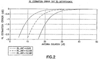
- the isolation could be more or less as shown in FIG. 2 .
- the "RL_ANT" are return losses of the antenna system. The required isolation is usually obtained through some combination of power level restrictions, isolators, directional couplers/splitters and/or antenna placement. The exemplary embodiments disclosed herein are capable of minimizing or even eliminating the means normally taken to maintain adequate isolation.
- exemplary techniques disclosed herein provide discrimination between the reflections of the signal that are emanating from the desired transmitter versus interference that couples in from other sources (e.g., another transmitter co-sited with the transmitter TX 161 that transmits the original signal and receives the reflected signal).
- circuitry in FIG. 1 would be further configured to perform determining an alarm should occur based on the return loss and outputting an indication of the alarm.
- Such indication could be sent externally by one or more antennas 158, via the networks 173, 175, or connected to an alarm (not shown) internally in base station 107 or through the one or more antennas 158, via the networks 173, 175, or via other circuitry (not shown).
- the resulting samples could represent the I component, the Q component, or, more likely, a combination of the two.
- This real sampling approach is often used to reduce the sampling rate by 2x but it then requires some type of time alignment procedure to ensure proper phase and can be difficult in the presence of interference.
- the current invention presents a more efficient way to detect a problem in the condition of an antenna and its cable/connector system.
- the current invention presets a method of obtaining a VSWR estimation using cross-correlation or spectrum analysis techniques with single axis sampling but without the need of strict 7me alignment. It assumes that the transmitted signal exists in complex form and that this signal can be mathematically rotated in phase and then single axis sampled for comparison against the single axis reflected signal. If the rotation is done over equally spaced intervals that spans one complete cycle, the average of the absolute value all such return loss ratios will approach the actual return loss ratio and the interference will be suppressed
- a forward signal is transmitted and a reflected signal occurs due to properties of the cable/connector system and such exemplary embodiments, presented herein, teach a method of obtaining a VSWR estimation using cross-correlation techniques with real sampling but without the restriction of strict time alignment.
- the signals present are only those that are desired and their (low level) intermodulation products thus the resulting time alignment can be quite accurate and robust.
- the reflected signal can be buried in noise and interfering signals reducing the confidence of the result.
- the minimization (or maximization) of the time alignment metric may be completely fooled and erroneous. This could significantly skew a mean estimation thus some intelligence would be required to throw out results that are below some minimum confidence level.
- the decision of what to keep and what to throw out can be very difficult to arrive at and will be a compromise between measurement confidence and time required to render an estimate. In fact, with large, sustained interference a measurement may never be rendered if the criteria are not optimal.
- An example of a technique disclosed herein completely eliminates the need for time alignment and eliminates the need to make hard decisions related to confidence of said result. This new approach is more predictable, much simpler to design and implement, and is overall a more robust solution suited especially to measurements where interference dominates the desired signal.
- time-alignment method involves finding time delay prior to estimating VSWR/RL while the current approach does not need time alignment in order to estimate VSWR/RL.
- cross-correlation needs to be performed which can fall apart completely in the presence of in-band or co-channel interferer that has high power (such as for a requirement of ⁇ 20dB of reflected signal-interferer rejection ratio). This is due to the fact that time alignment via delay search as performed in DAPD is always in a benign environment with a high Signal-Interference ratio.
- the distance of the fault is unknown; it may vary from OPEN to 100m, translating to 2ns to 2 ⁇ s in time.
- a System Identification algorithm essentially an N-tap FIR filter
- This will also take time depending on the size of the taps. Plus, if the System Identification matrix turns out to be singular, VSWR/RL would be unobtainable even though we manage to obtain the right time alignment.
- a time-alignment method requires more computation time in case of high co-channel interferer than the current method and a time-alignment method would not work well when high co-channel interferer is present.
- Such embodiments as described here can provide Time-To-Fault information and provide information about the nature of the fault such as the case if the fault is deemed OPEN/SHORT/capacitive/inductive based on the phase of the sine wave obtained from the invention as disclosed herein.
- This capability is in a sense a built-in TDR (Time Domain Reflectometer) inside a Base Station or other instrumentation utilizing this disclosed invention.
- the current invention makes use of the PDRX (Pre-Distortion Receiver) that likely already exists to serve the power amplifier pre-distortion function.
- PDRX Pre-Distortion Receiver
- the reflected signal is typically delayed due to the propagation time to and from the location of the dominant reflection and time is proportional to the distance. Correlation of the reflected signal against the transmitted signal yields the reflection coefficient as a function of time. But, since this result contains noise due to thermal effects as well as the modulation on the signal itself, a low pass filter is used to smooth the measurement.
- complex rotation of transmitted signal in discrete steps from - ⁇ /2 to ⁇ /2 and then correlation with the reflected signal can provide the cross-correlation result without needing time alignment
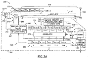
- FIG. 3A a block diagram is shown of a portion 300 of a transmitter 161, including an example of a VSWR apparatus 120 (although the VSWR apparatus 120 may also be separate from the transmitter 161). It should be noted that FIG. 3A , for simplicity, concentrates on the transmission path and does not show the reception path (see FIG. 1 from the antenna(s) 158 to the receiver, Rx, 162). However, this not to be construed as limiting.
- the portion 300 includes one or more power amplifiers 320. The power amplifiers are coupled to a cable/connector system 310, which is coupled to the antenna 158.
- the delay caused by the cable/connector system 310 is D/2 in this simple example.
- the VSWR apparatus 120 includes in this example sampling circuitries 340 and 345, buffers 155-1 and 155-2, memory 155-3, a correlator 370, and VSWR estimation control functionality 130.
- the one or more power amplifiers 320 and the VSWR estimation apparatus 120 are implemented in an integrated circuit (IC) 390, such as an application-specific integrated circuit(s) (ASIC).
- the VSWR estimation control functionality 130 therefore may be implemented as logic in the IC 390.
- some or all of the VSWR estimation control functionality 130 may be implemented in computer program code 153 (e.g., stored as firmware/software in memory 155, see FIG. 1 ) and executed by a processor 150, e.g., formed as part of the IC 390 or separate from the IC 390.
- sampling circuitry 340 could be implemented by one ASIC
- sampling circuitry 345 could be implemented by another ASIC
- the one or more memories 155, correlator 370, and VSWR estimation control 130 implemented by a third ASIC.
- Gate arrays or other programmed devices may also be used.
- aspects of the embodiments may be performed by hardware, software (executed by hardware), or some combination. This is really an implementation detail, trading off items like cost, space, VSWR reporting speed, and the like, but the general approaches herein are independent of this.
- FIG. 4 is a block diagram of an example of a logic flow diagram that illustrates the operation of an example of a method, a result of execution of computer program instructions embodied on a computer readable memory, and/or functions performed by logic implemented in hardware, in accordance with exemplary embodiments of this invention.
- a sampled version (e.g., set 380 of samples) of the composite transmitted signal waveform 330 is correlated with a sampled and delayed version (e.g., set 350 of samples) of the reflected signal waveform.
- the delay, d is varied from, in an example of an embodiment, zero to the longest delay (e.g., dMax) expected (2 x ANT_cable_length / velocity_of_propagation) which is on the order of 1.5 ⁇ sec (microseconds) for a typical base station site where ANT_cable_length is the antenna cable length and velocity_of_propagation is the velocity of propagation in the cable where only the cable/connector system is considered 310.
- dMax 2 x ANT_cable_length / velocity_of_propagation
- dB the longest delay
- the example of FIG. 3A uses a sampling point 341 for at least the sampling of the forward signal.
- the indicated delay, D is for the cable/connector system 310.
- the sampling of at least the forward signal 335 could occur at many different locations in the transmission path 192, e.g., at location 342, prior to the one or more power amplifiers 320 and as such can occur in the baseband 343.
- the sampling occurs without use of the demodulator 387.
- the transmission path 192 can start in the baseband 343 and conclude in the antenna(s) 158.
- the delay D can be quite large and include time delays for the power amplifier(s) 320, filters (not shown) if used, and other electronics.
- a signal waveform on the input 321 is transmitted by the one or more power amplifiers 320.
- a version of the amplified radio frequency signal waveform is shown as 330, which includes many symbols (in this example), a portion of which is shown as "...TX k-2 , TX k-1 , TX k , TX k+1 , TX k+2 ", and a radio frequency version of the forward signal is illustrated by reference 335-2.
- the forward RF signal 335-2 is sampled at a particular sampling rate (e.g., in megasamples per second, Msps) by the sampling circuitry 340, where in one example the sampling occurs after demodulation by the demodulator 387.
- the set 380 of samples includes in this example M samples, a portion of which is shown as "...S k-2-d , S k-1-d , S k-d , S k+1-d , S k+2-d ", where each S is a symbol corresponding to a symbol TX in the amplified waveform 330.
- a fixed length (e.g., M-length) set 380 of samples of the transmitted forward RF signal 335-2 is taken and stored in, e.g., a temporary buffer 155-1.
- a sample by sample correlation against the reflected signal waveform is done (this can be accomplished, for example with the first of the M samples or some other reference point, where another fixed length, e.g., P-length, set 350 of samples of the reflected waveform 355 is taken by the sampling circuitry 345, which includes a demodulator 397 from which the samples 350 are generated and is stored in, e.g., another temporary buffer 155-2, although it should be noted the two buffers 155-1 and 155-2 could be a single large buffer).
- the set 350 of samples includes in this example P samples, a portion of which is shown as "... ⁇ S k-2-D , ⁇ S k-1-D , ⁇ S k-D , ⁇ S k+1-D , ⁇ S k+2-D ", where ⁇ is the reflection coefficient and each S is a symbol corresponding to a symbol TX in the amplified waveform 330. A maximum search of the results then yields the return loss estimate.
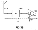
- FIG. 3B shows a block diagram of a portion of a reception path 193 (also illustrated in FIG. 3A ) used as a portion of an example of a VSWR apparatus.
- the portion includes an ADC (analog-to-digital converter 388) and part of the receiver 162, including at least a demodulator 399, which produces the set 350 of samples.
- ADC analog-to-digital converter 388
- P typically P will be greater than or equal to M, although this is not a limitation.
- the "receiver" ADC in this case must be on the same line as the TX is operating on. That is the reflection being observed. While it might be possible to use the main receiver, that would require switching it to the TX path and tuning it to the TX frequency. Practical implications are that in an FDD system RX and TX must be simultaneous.
- a sample by sample correlation against the reflected signal waveform is performed by the correlator 370, which in an example is a set of logic operations implemented in the IC 390 (or may be performed by software executed by hardware, or both).
- FIG. 3A therefore also illustrates that a number Z of five (in this example, typically Z will be much higher, such as 128 or more samples) samples in the set 380 having indices X through X+4 are aligned with the number Z of five samples in the set 350 having indices Y through Y+4. A correlation is performed and the result is stored.
- the number, Z, of samples in the set 380 is slid across the samples in set 350. If a maximum index (for the samples in the set 350) is not reached, another correlation is performed.
- the correlation formula from before may be used, where f [ k ] is a number Z from the set 350 of samples, and g [ k ] is a number Z from the set 380 of samples, the f [ k ] is slid relative to g [ k ] for each correlation, and d Max is Y Max-1 .
- Each CC [ k ] has a set of Z correlation coefficient values, and there will be d Max +1 (i.e., Y Max ) sets of results 371 in this example.
- each index (X or Y) corresponds to a sample period, the indices corresponding to and can be converted to delays.
- a first correlation after alignment is performed using X to X+4 samples of the set 380 and Y to Y+4 samples of the set 350.
- the next correlation is performed using X to X+4 samples of the set 380 and Y+1 to Y+5 samples of the set 350 (i.e., the X to X+4 samples of the set 380 are slid to Y+1 to Y+5 samples of the set 350).
- the next correlation is performed using X to X+4 samples of the set 380 and Y+2 to Y+6 samples of the set 350 (i.e., the X to X+4 samples of the set 380 are slid to Y+2 to Y+6 samples of the set 350).
- the return loss estimate or an indication thereof i.e., the maximum value in dB
- output 396 e.g., to one of the processors 150 (see FIG. 1 ). This may be used to determine whether an alarm is suitable and, if so, to output, if desired, an indication of the alarm.
- one or more function(s) may be performed in response to the alarm. It should also be noted that it is not necessary to only return the value of the peak value. Rather, the entire vector can be returned giving the reflection coefficient versus time (distance) for the entire system. In this way this algorithm provides the same sort of information as would be provided by a Time Domain Reflectometer (TDR).
- TDR Time Domain Reflectometer
- the set 380 of samples is delayed and the set 350 of samples is not in the examples.
- the set 350 of samples may be delayed and the set 380 of samples may not be delayed.
- the sliding of the forward signal samples "across" the reflected signal samples is a "movement" of the forward signal samples relative to the reflected signal samples. That is, the reflected signal is effectively kept stationary while the forward signal is moved. In the example of FIG.
- this is done by increasing the Y index value relative to the number Z of samples in the set 380 of forward signal samples. However this could also be done by decreasing the Y index value relative to number Z of samples in the set 380 of forward signal samples. That is, X aligns with Y in the example above, then X aligns with Y+1...; it could also be the case that X aligns with Y, then X aligns with Y-1..., so that the number Z of samples in the set 380 go "backwards" through the samples in the set 350.
- the VSWR estimation control functionality 130 may cause the operations of the proposed method to occur.
- the signal(s) 381 may be used by the VSWR estimation control functionality 130 to load the correlator 370 with a selected delay, d, and to modify or cause to be modified the delay, d.
- the signal(s) 381 may be used by the VSWR estimation control functionality 130 to cause the sampling circuitry 340 to take the samples.
- the sampling circuitry 340 is internally programmed to take the samples, where the sampling of reflected signal can occur at any time and the estimator block in block diagram in FIG. 5 will calculate the Return Loss.
- the signal(s) 381 is/are used to inform the VSWR estimation control functionality 130 (and/or the correlator 370) that the temporary buffers 155-1, 155-2 are full.
- the cross correlator 370 performs the cross correlations automatically and outputs the results 371 to the memory 155-3 and the signal(s) 381 are used to inform the VSWR estimation control functionality 130 as to the completion of all the correlations. Still other embodiments are possible, and the examples presented here should not be construed as being limiting.
- FIG. 4 is a block diagram of an example of a logic flow diagram that illustrates the operation of an example of a method, a result of execution of computer program instructions embodied on a computer readable memory, and/or functions performed by logic implemented in hardware, in accordance with exemplary embodiments of this invention where each of the blocks in FIG. 4 a represent step in the method.
- the first step 402 is to measure values of a radio frequency signal that comprises a forward signal and a reflected version of the forward signal in a cable/connector system.
- FIG. 5 a radio transmitter and PDRX receiver model
- V dac I t + jQ t
- a complex modulator 506 whose carrier frequency is ⁇ c then modulates the DAC output and the real part 508 of the modulator's output 510 is transmitted out of the radio.
- V tx Re V dac ⁇ e j ⁇ c t
- equations (2) and (3) assume complex notation.
- the I ( kT ) and Q (kT) signals are converted to continuous time signals by independent DACs and then applied to a quadrature modulator.
- the quadrature modulator modulates (multiplies) the I ( t ) component by cos( ⁇ c t) and the Q ( t ) component by sin( ⁇ c t) and then combines their voltages.
- V pdrx ′ ⁇ 2 . I t ⁇ ⁇
- V pdrx ′ ⁇ ′ . I t ⁇ ⁇
- V pdrx Re ⁇ V bb ⁇ by delaying Re ⁇ V bb ⁇ by ⁇ .
- cross-correlation 524 of the aligned signal with V pdrx yields p, the magnitude of reflection coefficient after removing the other amplitude scaling factors.
- V rotate I kT + jQ kT .
- e j ⁇ I kT + jQ kT . cos ⁇ + j sin ⁇
- V bb ′ Re
- V rotate I kT cos ⁇ ⁇ Q kT sin ⁇
- ⁇ xcorr abs ⁇ ′ . cos ⁇ . ⁇ kT ⁇
- mean cos ⁇ ⁇ ′ ⁇ 1 ⁇ ⁇ ⁇ / 2 ⁇ / 2 ⁇ cos ⁇ .
- An advantage of the current invention is that the need for a generally complex and sometimes unreliable delay search algorithm is eliminated. Other advantages are that the overall method is easier to implement, takes less computation, and is generally more robust, especially in the presence of noise or interference than those methods used at the time of this invention. This invention will better address the interference limitations associated with the conventional (power meter based) methods. This method has been tested in the lab and its benefits confirmed therein.
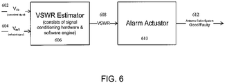
- FIG. 6 is a block diagram representation of the physical inputs and physical outputs of an exemplary embodiment of the invention.
- Both the transmitted signal 602 and the reflected signal 604 are entered into the VSWR Estimator 606, which consists of signal conditioning hardware and the software engine. Thereafter, the VSWR 608 enters an alarm actuator 610 with the resultant 612 of whether the antenna cable system cable system is good or faulty, wherein if it is good then the cable system can be used and if faulty than the cable system needs to be replaced.
- Embodiments of the present invention may be implemented in software (executed by one or more processors), hardware (e.g., an application specific integrated circuit), or a combination of software and hardware.
- the software e.g., application logic, an instruction set
- a "computer-readable medium” may be any media or means that can contain, store, communicate, propagate or transport the instructions for use by or in connection with an instruction execution system, apparatus, or device, such as a computer, with one example of a computer described and depicted, e.g., in FIG. 1 .
- a computer-readable medium may comprise a computer-readable storage medium (e.g., memory(ies) 155 or other device) that may be any media or means that can contain or store the instructions for use by or in connection with an instruction execution system, apparatus, or device, such as a computer.
- a computer-readable storage medium e.g., memory(ies) 155 or other device
- the different functions discussed herein may be performed in a different order and/or concurrently with each other. Furthermore, if desired, one or more of the above-described functions may be optional or may be combined.
- An example of an embodiment which can be referred to as item 1, is a method that comprises measuring values of a radio frequency signal that comprises: a forward signal and a reflected version of the forward signal in a cable/connector system; inputting the measured values into a VSWR apparatus; mathematically rotate in phase, in the VSWR apparatus, a complex form of a transmitted signal; sampling a single axis of the transmitted signal; comparing the sample against a single axis reflected signal; applying the rotation over equally spaced intervals spanning one complete cycle; taking an absolute value of each return loss ratio; determining the mean of the absolute values; associating the mean value with a return loss of the cable/connector system; and sending the mean value from the VSWR apparatus to an alarm actuator and activating the alarm based on the mean value in relation to a threshold.
- An example of a further embodiment, which can be referred to as item 2, is the method of item 1 wherein the reflected radio frequency signal is a reflected version of a radio frequency version of the forward signal, wherein reflections occur at least by one or both of the cable/connector system or the one or more antennas.
- An example of a further embodiment, which can be referred to as item 3, is the method of any one of items 1 or 2, wherein the rotation is at an interval of ⁇ /2.
- An example of a further embodiment, which can be referred to as item 4, is the method of any one of items 1 to 3, wherein the forward signal and the reflected signal are measured by the same method.
- An example of a further embodiment, which can be referred to as item 5, is the method of any one of items 1 to 4, wherein the maximum delay is determined at least by a value of twice an antenna cable length in the cable/connector system divided by a velocity of propagation of the forward radio frequency signal in the cable.
- An example of a further embodiment, which can be referred to as item 6, is the method of any one of items 1 to 5, wherein the sampling is from baseband to one or more antennas a transmission path.
- An example of a further embodiment, which can be referred to as item 7, is the method of any one of items 1 to 6, wherein the mean value is converted to a decibel value indicative of the return loss of the cable/connector system.
- An example of a further embodiment, which can be referred to as item 8, is the method of any one of items 1 to 7, further comprising outputting an indication of the alarm.
- An example of another embodiment, which can be referred to as item 9, is a computer program comprising program code for executing the method according to any of claims 1 to 8.
- a computer program product embodied on a non-transitory computer-readable medium in which a computer program is stored that, when being executed by a computer, would be configured to provide instructions to control or carry out any of the methods of claims 1 to 8.
- An example of another embodiment of the present invention is an apparatus comprising at least one processor and at least one memory including computer program code, wherein the at least one memory and the computer code are configured, with the at least one processor, to cause the apparatus to at least perform the following: measuring values of a radio frequency signal that comprises a forward signal and a reflected version of the forward signal in a cable/connector system; inputting the measured values into a VSWR apparatus; mathematically rotate in phase, in the VSWR apparatus, a complex form of a transmitted signal; sampling a single axis of the transmitted signal; comparing the sample against a single axis reflected signal; applying the rotation over equally spaced intervals spanning one complete cycle; taking an absolute value of each return loss ratio; determining the mean of the absolute values; associating the mean value with a return loss of the cable/connector system; and sending the mean value from the VSWR apparatus to an alarm actuator and activating the alarm based on the mean value in relation to a threshold.
- An example of a further embodiment, which can be referred to as item 12, is the apparatus of item 11, wherein the reflected radio frequency signal is a reflected version of a radio frequency version of the forward signal, wherein reflections occur at least by one or both of the cable/connector system or the one or more antennas.
- An example of a further embodiment, which can be referred to as item 13, is the apparatus of any one of items 11 or 12, wherein the rotation is at an interval of ⁇ /2.
- An example of a further embodiment, which can be referred to as item 14, is the apparatus of any one of items 11 to 13, wherein the forward signal and the reflected signal are measured by the same method.
- An example of a further embodiment, which can be referred to as item 15, is the apparatus of any one of claims 11 to 14, wherein the maximum delay is determined at least by a value of twice an antenna cable length in the cable/connector system divided by a velocity of propagation of the forward radio frequency signal in the cable.
- An example of a further embodiment, which can be referred to as item 16, is the apparatus of any one of items 11 to 15, wherein the sampling is from baseband to one or more antennas a transmission path.
- An example of a further embodiment, which can be referred to as item 17, is the apparatus of any one of items 11 to 16, wherein the mean value is converted to a decibel value indicative of the return loss of the cable/connector system.
- An example of a further embodiment, which can be referred to as item 18, is the apparatus of any one of items 11 to 17, wherein the at least one memory and the computer code are further configured, with the at least one processor, to cause the apparatus to at least further perform outputting an indication of the alarm.
- a base station comprising the apparatus of any one of claims 11 to 17.
- An example of another embodiment of the present invention is an apparatus comprising means for measuring values of a radio frequency signal that comprises a forward signal and a reflected version of the forward signal in a cable/connector system; means for inputting the measured values into a VSWR; means for mathematically rotate in phase, in the VSWR, a complex form of a transmitted signal; means for sampling a single axis of the transmitted signal; means for comparing the sample against a single axis reflected signal; means for applying the rotation over equally spaced intervals spanning one complete cycle; means for taking an absolute value of each return loss ratio; means for determining the mean of the absolute values; means for associating the mean value with a return loss of the cable/connector system; and means for sending the mean value from the VSWR apparatus to an alarm actuator and activating the alarm based on the mean value in relation to a threshold.
- An example of a further embodiment, which can be referred to as item 22, is the apparatus of item 21, wherein the reflected radio frequency signal is a reflected version of a radio frequency version of the forward signal, wherein reflections occur at least by one or both of the cable/connector system or the one or more antennas.
- An example of a further embodiment, which can be referred to as item 23, is the apparatus of any one of items 21 or 22, wherein the rotation is at an interval of ⁇ /2.
- An example of a further embodiment, which can be referred to as item 24, is the apparatus of any one of items 21 to 23, wherein the forward signal and the reflected signal are measured by the same method.
- An example of a further embodiment, which can be referred to as item 25, is the apparatus of any one of claims 21 to 24, wherein the maximum delay is determined at least by a value of twice an antenna cable length in the cable/connector system divided by a velocity of propagation of the forward radio frequency signal in the cable.
- An example of a further embodiment, which can be referred to as item 26, is the apparatus of any one of items 21 to 25, wherein the sampling is from baseband to one or more antennas a transmission path.
- An example of a further embodiment, which can be referred to as item 27, is the apparatus of any one of items 21 to 26, wherein the mean value is converted to a decibel value indicative of the return loss of the cable/connector system.
- An example of a further embodiment, which can be referred to as item 28, is the apparatus of any one of items 21 to 27, further comprising means for outputting an indication of the alarm.
- At least one integrated circuit comprising the apparatus of any one of claims 21 to 27.
- a base station comprising the apparatus of any one of claims 21 to 27.
Landscapes
- Physics & Mathematics (AREA)
- General Physics & Mathematics (AREA)
- Engineering & Computer Science (AREA)
- Electromagnetism (AREA)
- Computer Networks & Wireless Communication (AREA)
- Signal Processing (AREA)
- Monitoring And Testing Of Transmission In General (AREA)
- Mobile Radio Communication Systems (AREA)
- Radar Systems Or Details Thereof (AREA)
- Quality & Reliability (AREA)
Abstract
Description
- This invention relates generally to wireless transmissions and, more specifically, relates to antenna usage in wireless transmissions.
- This section is intended to provide a background or context to the invention disclosed below. The description herein may include concepts that could be pursued, but are not necessarily ones that have been previously conceived, implemented or described. Therefore, unless otherwise explicitly indicated herein, what is described in this section is not prior art to the description in this application and is not admitted to be prior art by inclusion in this section. Abbreviations that may be found in the specification and/or the drawing figures are defined below at the end of the specification but prior to the claims.
- In a wireless transmission system, a transmitter is coupled to an antenna through a cable/connector system. Assuming an ideal transmission system, there will be no power reflected back from the load. That is, the transmission power in the "forward" signal is all applied through the cable/connector system to the antenna. Real transmission systems, however, have reflections due to, e.g., impedance mismatch somewhere in the cable/connector system or antenna.
- Cellular operators need a way to monitor, in real-time, the condition of the antenna and its cable/connector system. A common indicator of this condition is the VSWR although there are many other equivalents including reflection coefficient and Return Loss. Return loss is the ratio of the forward (incident) and reflected powers, converted to dB. Most commonly, directional couplers, bridges or circulators are used to separate the two power signals (forward and reflected power signals) followed by detectors to quantify their respective amplitudes. While the forward signal tends to be quite pure, the reflected signal is returning from the antenna and may be accompanied by extraneous energy, which is "noise" insofar as the measurement is concerned.
- This "noise" may be due to other transmitters electrically combined with the desired transceiver or from co-sited transmitters coupling in through the antennas. Either way, the reflected detector will report more power than the reflection itself is producing resulting in a lower return loss which may cause a false alarm. For example, recent advances in complex modulations with a significant time domain component, multiple carriers and especially co-siting can make the task of monitoring the condition of the antenna and its cable/connector system more difficult than in the past.
- Multi-carrier/complex modulation schemes with traditional schemes suffer from problems. For example, for complex modulation and multiple carriers, typically, the log detectors used for this are not true power detectors (i.e., do not calculate true root-mean-squared power or measure heating in a load, or the like) so the result depends on the nature of the signal. For example, between a single CW carrier and a wideband CDMA or an LTE carrier (which resembles Gaussian noise), all at the same output power, the detector output could vary up to as much as approximately 5dB. For example, the "noise" in the reflected signal may be due to other transmitters electrically combined with the desired transmitter or from co-sited transmitters coupling in through the antenna. Either way, a reflection detector will report more power than the reflection itself is producing, resulting in a lower return loss which may cause a false alarm. That is, since the return loss is a ratio of the forward and reflected powers, anything that erroneously increases the reported reflective power will decrease the return loss (assuming the forward power is stable), and an alarm can be reported due to the artificially reduced return loss.
- It would be beneficial to improve the ability to monitor, in real-time, the condition of the antenna and its cable/connector system. Problems such as described above are tackled by the present invention as described in the following paragraphs
- This section contains examples of possible implementations which should not be construed as limiting the invention in any way.
- An example of an embodiment is a method that comprises measuring values of a radio frequency signal that comprises a forward signal and a reflected version of the forward signal in a cable/connector system; inputting the measured values into a VSWR apparatus; mathematically rotate in phase, in the VSWR apparatus, a complex form of a transmitted signal; sampling a single axis of the transmitted signal; comparing the sample against a single axis reflected signal; applying the rotation over equally spaced intervals spanning one complete cycle; taking an absolute value of each return loss ratio; determining the mean of the absolute values; associating the mean value with a return loss of the cable/connector system; and sending the mean value from the VSWR apparatus to an alarm actuator and activating the alarm based on the mean value in relation to a threshold.
- Another example of an embodiment is a computer program product comprising program code for executing the method according to the previous paragraph. A further example of an embodiment is the computer program according to this paragraph, wherein the computer program is a computer program product comprising a computer-readable medium bearing computer program code embodied therein for use with a computer.
- An additional example of an embodiment is an apparatus comprising at least a memory and at least a processor. The memory could hold computer program code that is executed by the processor. The apparatus includes additional circuitry configured to perform at least the following: measuring values of a radio frequency signal that comprises a forward signal and a reflected version of the forward signal in a cable/connector system; inputting the measured values into a VSWR apparatus; mathematically rotate in phase, in the VSWR apparatus, a complex form of a transmitted signal; sampling a single axis of the transmitted signal; comparing the sample against a single axis reflected signal; applying the rotation over equally spaced intervals spanning one complete cycle; taking an absolute value of each return loss ratio; determining the mean of the absolute values; associating the mean value with a return loss of the cable/connector system; and sending the mean value from the VSWR apparatus to an alarm actuator and activating the alarm based on the mean value in relation to a threshold. The circuitry may comprise one or more processors. A further example of an embodiment is at least one integrated circuit comprising the apparatus of this paragraph. Another example of an embodiment is a base station comprising the apparatus of this paragraph.
- Another example of an embodiment is an apparatus, comprising means for measuring values of a radio frequency signal that comprises a forward signal and a reflected version of the forward signal in a cable/connector system; means for inputting the measured values into a VSWR; means for mathematically rotate in phase, in the VSWR, a complex form of a transmitted signal; means for sampling a single axis of the transmitted signal; means for comparing the sample against a single axis reflected signal; means for applying the rotation over equally spaced intervals spanning one complete cycle; means for taking an absolute value of each return loss ratio; means for determining the mean of the absolute values; means for associating the mean value with a return loss of the cable/connector system; and means for sending the mean value from the VSWR apparatus to an alarm actuator and activating the alarm based on the mean value in relation to a threshold. A further example of an embodiment is at least one integrated circuit comprising the apparatus of this paragraph. Another example of an embodiment is a base station comprising the apparatus of this paragraph.
- As yet another example of an embodiment, an apparatus is disclosed. The apparatus includes one or more processors, and one or more memories including computer program code. The one or more memories and the computer program code are configured, with the one or more processors, to cause the apparatus to perform or control at least the following: measuring values of a radio frequency signal that comprises a forward signal and a reflected version of the forward signal in a cable/connector system; inputting the measured values into a VSWR apparatus; mathematically rotate in phase, in the VSWR apparatus, a complex form of a transmitted signal; sampling a single axis of the transmitted signal; comparing the sample against a single axis reflected signal; applying the rotation over equally spaced intervals spanning one complete cycle; taking an absolute value of each return loss ratio; determining the mean of the absolute values; associating the mean value with a return loss of the cable/connector system; and sending the mean value from the VSWR apparatus to an alarm actuator and activating the alarm based on the mean value in relation to a threshold.
- In the attached Drawing Figures:
-
FIG. 1 illustrates an example of a system in which the exemplary embodiments of the instant invention may be practiced; -
FIG. 2 is a chart of measurement error versus isolation; -
FIG. 3A is a block diagram of a portion of a transmitter including (a portion of) an example of a VSWR apparatus; -
FIG. 3B is a block diagram of a portion of a reception path used as a portion of an example of a VSWR apparatus; -
FIG. 4 is a block diagram of an example of a logic flow diagram that illustrates the operation of an example of a method, a result of execution of computer program instructions embodied on a computer readable memory, and/or functions performed by logic implemented in hardware, in accordance with exemplary embodiments of this invention; -
FIG. 5 is a block diagram of a radio transmitter and PDRX receiver model; and -
FIG. 6 is a block diagram representation of the physical inputs and physical outputs of an exemplary embodiment of the invention. - As noted above, cellular operators need a way to monitor, in real time, the condition of the antenna and its cable/connector system. The most common indicator of this quality is the VSWR or, equivalently, the return loss. Interference present in co-siting or shared antenna installations makes the determination difficult and subject to false alarms. Mitigation methods have been disclosed that use spectrum analysis or cross correlation techniques to discriminate against interference. These approaches are straight forward if both the forward and reflected signals contain complex or quadrature (I and Q) samples. However, if only single axis samples are available, as is often the case to reduce the sampling rate, then the resulting samples could represent the I component, the Q component or, more likely, some combination of the two. This generally requires some type of time alignment procedure to ensure proper phase. It can be difficult and unreliable in the presence of interference.
- This invention teaches a method of obtaining a VSWR estimation using cross-correlation or spectrum analysis techniques with single axis sampling but without the need of strict time alignment. It assumes that the transmitted signal exists in complex form and that this signal can be mathematically rotated in phase and then single axis sampled for comparison against the single axis reflected signal. If the rotation is done over equally spaced intervals that spans one complete cycle, the average of the absolute value all such comparisons will approach the actual return loss value and the interference will be suppressed.
- Before proceeding with description of additional problems with conventional systems and how exemplary embodiments address these problems, reference is now made to
FIG. 1 , which illustrates an example of a system in which the exemplary embodiments of the instant invention may be practiced. InFIG. 1 , a user equipment (UE) 110 is in wireless communication with awireless network 100 via awireless link 115 with base station 107 (such as an eNB or NodeB), which is an LTE base station (in this example) providing access to and from thewireless network 100. Theuser equipment 110 includes one ormore antennas 128. - The
network 100 includes thebase station 107. Although an LTE base station is used herein as an example, the exemplary embodiments are applicable to any wireless transmission system. Thebase station 107 includes one ormore processors 150, one ormore memories 155, one or more network interfaces (N/W I/F(s)) 165, and one or more transceivers 160 (each comprising a transmitter, Tx, 161 and a receiver, Rx, 162) interconnected through one ormore buses 157. In thetransmitter 161, aVSWR estimation apparatus 120 is used to perform VSWR estimation in accordance with exemplary embodiments of the instant invention. The location, as indicated byreference 120, of the VSWR estimation apparatus is merely an example. Portions 120-1 of theVSWR estimation apparatus 120 may be included after the Rx and Tx antenna paths are combined (as shown by reference 120-1), or portions 120-2 may be implemented in thetransmitter 161. There are multiple locations in a transmission path 192 (and also in part of the reception path 193) where some or all of theVSWR estimation apparatus 120 may reside. The one ormore transceivers 160 are connected to one ormore antennas 158. The one ormore memories 155 includecomputer program code 153, which in this example comprises VSWRestimation control functionality 130, which may partially or completely perform and/or control VSWR estimation. The one ormore memories 155 and thecomputer program code 153 are configured to, with the one ormore processors 150, cause thebase station 107 to perform one or more of the operations as described herein. The VSWRestimation control functionality 130 may be implemented in the computer program code 153 (executed by the one or more processors 150), or implemented in hardware such as logic in an integrated circuit as described below, or as some combination of computer program code and hardware. - The one or
more network interfaces 165 communicate over networks such as thenetworks base station 107 may communicate with other base stations using, e.g.,network 173. Thenetwork 173 may be wired or wireless or both and may implement, e.g., an X2 interface. Thebase station 107 may use thenetwork 175 to communicate with a core portion of thewireless network 100. - The computer
readable memory 155 may be of any type suitable to the local technical environment and may be implemented using any suitable data storage technology, such as semiconductor based memory devices, flash memory, magnetic memory devices and systems, optical memory devices and systems, fixed memory and removable memory. The processor(s) 150 may be of any type suitable to the local technical environment, and may include one or more of general purpose computers, special purpose computers, general or special purpose integrated circuits, microprocessors, digital signal processors (DSPs) and processors based on a multi-core processor architecture, as non-limiting examples. - As stated above, there could be noise in a reflected signal that causes a reflection detector to report more power than the reflection itself is producing, resulting in a lower return loss which may cause a false alarm. In order to obtain adequate accuracy, it is generally necessary to suppress the interfering signals by roughly 25dB or more. But, depending on the tolerable error (see the RL, Return Loss, Estimation Error), the isolation could be more or less as shown in
FIG. 2 . The "RL_ANT" are return losses of the antenna system. The required isolation is usually obtained through some combination of power level restrictions, isolators, directional couplers/splitters and/or antenna placement. The exemplary embodiments disclosed herein are capable of minimizing or even eliminating the means normally taken to maintain adequate isolation. For instance, exemplary techniques disclosed herein provide discrimination between the reflections of the signal that are emanating from the desired transmitter versus interference that couples in from other sources (e.g., another transmitter co-sited with thetransmitter TX 161 that transmits the original signal and receives the reflected signal). - Nonetheless, the circuitry in
FIG. 1 would be further configured to perform determining an alarm should occur based on the return loss and outputting an indication of the alarm. Such indication could be sent externally by one ormore antennas 158, via thenetworks base station 107 or through the one ormore antennas 158, via thenetworks - A method was disclosed previously in Barabash et al, "VSWR Estimation Using Cross-correlation to Suppress External Interference",
PCT application WO 2014/058432, filed on 12 October 2012 , which uses cross correlation to discriminate against interference. However, such cross-correlation as discussed therein needs an accurate time alignment to find a fault in the condition of an antenna and its cable/connector system. Then, the cross-correlation calculations are straight forward if both the forward and reflected signals contain complex or quadrature (I and Q) samples. However, if only single axis samples (either I or Q) are available, the problem is more difficult. Specifically, depending on the phase of the sampler, the resulting samples could represent the I component, the Q component, or, more likely, a combination of the two. This real sampling approach is often used to reduce the sampling rate by 2x but it then requires some type of time alignment procedure to ensure proper phase and can be difficult in the presence of interference. - In contrast, the current invention presents a more efficient way to detect a problem in the condition of an antenna and its cable/connector system. The current invention presets a method of obtaining a VSWR estimation using cross-correlation or spectrum analysis techniques with single axis sampling but without the need of strict 7me alignment. It assumes that the transmitted signal exists in complex form and that this signal can be mathematically rotated in phase and then single axis sampled for comparison against the single axis reflected signal. If the rotation is done over equally spaced intervals that spans one complete cycle, the average of the absolute value all such return loss ratios will approach the actual return loss ratio and the interference will be suppressed
- By way of a brief and non-limiting introduction, in exemplary embodiments a forward signal is transmitted and a reflected signal occurs due to properties of the cable/connector system and such exemplary embodiments, presented herein, teach a method of obtaining a VSWR estimation using cross-correlation techniques with real sampling but without the restriction of strict time alignment.
- Prior to computing the cross correlation, a technique must be employed to time align the real sampler phase so that the results purely represent the I (or Q) component. Then, the reflected samples can be correlated against the I (or Q) component of the forward signal in order to estimate the return loss.
- These techniques typically involve either a priori knowledge of the phase offset or use some adaptive technique to align the phase such that the error between the forward signal and the reflected signal are minimized. The latter is very often necessary for Digital Adaptive Pre-Distortion (DAPD) and could potentially be used for this cross-correlation calculation.
- In DAPD, the signals present are only those that are desired and their (low level) intermodulation products thus the resulting time alignment can be quite accurate and robust. However, for a return loss estimator, the reflected signal can be buried in noise and interfering signals reducing the confidence of the result. In fact, in the case of significant interference, the minimization (or maximization) of the time alignment metric may be completely fooled and erroneous. This could significantly skew a mean estimation thus some intelligence would be required to throw out results that are below some minimum confidence level. The decision of what to keep and what to throw out can be very difficult to arrive at and will be a compromise between measurement confidence and time required to render an estimate. In fact, with large, sustained interference a measurement may never be rendered if the criteria are not optimal.
- An example of a technique disclosed herein completely eliminates the need for time alignment and eliminates the need to make hard decisions related to confidence of said result. This new approach is more predictable, much simpler to design and implement, and is overall a more robust solution suited especially to measurements where interference dominates the desired signal.
- Additional advantages of the approach disclosed herein over a time-alignment method is that the latter involves finding time delay prior to estimating VSWR/RL while the current approach does not need time alignment in order to estimate VSWR/RL. To find time delay apriori in a time-alignment method, cross-correlation needs to be performed which can fall apart completely in the presence of in-band or co-channel interferer that has high power (such as for a requirement of ~20dB of reflected signal-interferer rejection ratio). This is due to the fact that time alignment via delay search as performed in DAPD is always in a benign environment with a high Signal-Interference ratio. Moreover, in a time-alignment method, the distance of the fault is unknown; it may vary from OPEN to 100m, translating to 2ns to 2µs in time. In order for time alignment to work, there is a need to perform cross-correlation every time for VSWR unlike DAPD, where it is done only once during initialization of the base station. After time alignment, there is also a need to implement a System Identification algorithm (essentially an N-tap FIR filter) to estimate VSWR/RL value. This will also take time depending on the size of the taps. Plus, if the System Identification matrix turns out to be singular, VSWR/RL would be unobtainable even though we manage to obtain the right time alignment. Thus a time-alignment method requires more computation time in case of high co-channel interferer than the current method and a time-alignment method would not work well when high co-channel interferer is present.
- Such embodiments as described here can provide Time-To-Fault information and provide information about the nature of the fault such as the case if the fault is deemed OPEN/SHORT/capacitive/inductive based on the phase of the sine wave obtained from the invention as disclosed herein. This capability is in a sense a built-in TDR (Time Domain Reflectometer) inside a Base Station or other instrumentation utilizing this disclosed invention.
- Furthermore, thresholds could be established above which would give different indications of fault and would yield different alarm thresholds. The current invention makes use of the PDRX (Pre-Distortion Receiver) that likely already exists to serve the power amplifier pre-distortion function. By way of a switch, it can be used to monitor the signal being transmitted and the reflected signal. This is not essential but does eliminate the need for a dedicated receiver. The reflected signal is typically delayed due to the propagation time to and from the location of the dominant reflection and time is proportional to the distance. Correlation of the reflected signal against the transmitted signal yields the reflection coefficient as a function of time. But, since this result contains noise due to thermal effects as well as the modulation on the signal itself, a low pass filter is used to smooth the measurement. As will be discussed in detail below, complex rotation of transmitted signal in discrete steps from -π/2 to π/2 and then correlation with the reflected signal can provide the cross-correlation result without needing time alignment
- Additional detail for certain exemplary embodiments is provided by reference to
FIGs. 3A ,3B ,4 ,5 , and6 . Turning toFIG. 3A , a block diagram is shown of aportion 300 of atransmitter 161, including an example of a VSWR apparatus 120 (although theVSWR apparatus 120 may also be separate from the transmitter 161). It should be noted thatFIG. 3A , for simplicity, concentrates on the transmission path and does not show the reception path (seeFIG. 1 from the antenna(s) 158 to the receiver, Rx, 162). However, this not to be construed as limiting. Theportion 300 includes one ormore power amplifiers 320. The power amplifiers are coupled to a cable/connector system 310, which is coupled to theantenna 158. The delay caused by the cable/connector system 310 is D/2 in this simple example. TheVSWR apparatus 120 includes in thisexample sampling circuitries correlator 370, and VSWRestimation control functionality 130. In this example , the one ormore power amplifiers 320 and theVSWR estimation apparatus 120 are implemented in an integrated circuit (IC) 390, such as an application-specific integrated circuit(s) (ASIC). The VSWRestimation control functionality 130 therefore may be implemented as logic in theIC 390. However, some or all of the VSWRestimation control functionality 130 may be implemented in computer program code 153 (e.g., stored as firmware/software inmemory 155, seeFIG. 1 ) and executed by aprocessor 150, e.g., formed as part of theIC 390 or separate from theIC 390. - It should be noted that although only one ASIC is shown, there may be multiple ASICs or other hardware elements. For instance, the
sampling circuitry 340 could be implemented by one ASIC, thesampling circuitry 345 could be implemented by another ASIC, and the one ormore memories 155,correlator 370, andVSWR estimation control 130 implemented by a third ASIC. Gate arrays or other programmed devices may also be used. Furthermore, aspects of the embodiments may be performed by hardware, software (executed by hardware), or some combination. This is really an implementation detail, trading off items like cost, space, VSWR reporting speed, and the like, but the general approaches herein are independent of this. - The operation of the
portion 300 of thetransmitter 161 and of theVSWR apparatus 120 is described in relation toFIG. 3A and also in relation toFIG. 4. FIG. 4 is a block diagram of an example of a logic flow diagram that illustrates the operation of an example of a method, a result of execution of computer program instructions embodied on a computer readable memory, and/or functions performed by logic implemented in hardware, in accordance with exemplary embodiments of this invention. - In an example of an embodiment of the instant invention, rather than using individual forward and reflected signal power detectors, a sampled version (e.g., set 380 of samples) of the composite transmitted
signal waveform 330 is correlated with a sampled and delayed version (e.g., set 350 of samples) of the reflected signal waveform. The delay, d, is varied from, in an example of an embodiment, zero to the longest delay (e.g., dMax) expected (2 x ANT_cable_length / velocity_of_propagation) which is on the order of 1.5 µsec (microseconds) for a typical base station site where ANT_cable_length is the antenna cable length and velocity_of_propagation is the velocity of propagation in the cable where only the cable/connector system is considered 310. However, as described below, this is merely an example and the longest delay may be dramatically different from the formula just presented. A forward signal is aligned with a reflected signal. For each delay, the correlation is calculated and the maximum value found is converted to dB. It represents the best estimate of the return loss and the delay represents the time and therefore the distance to the reflection. Any component of the reflected signal that is not just a scaled version of the transmitted signal does not contribute to the correlation and is thus suppressed. - The example of
FIG. 3A uses asampling point 341 for at least the sampling of the forward signal. Thus, the indicated delay, D, is for the cable/connector system 310. However, this is merely an example, and the sampling of at least the forward signal 335 could occur at many different locations in thetransmission path 192, e.g., atlocation 342, prior to the one ormore power amplifiers 320 and as such can occur in thebaseband 343. This is indicated by reference 335-1, which is a baseband version of the forward signal 335 that is transmitted. For this example, the sampling occurs without use of thedemodulator 387. In this case, thetransmission path 192 can start in thebaseband 343 and conclude in the antenna(s) 158. Furthermore, in this case, the delay D can be quite large and include time delays for the power amplifier(s) 320, filters (not shown) if used, and other electronics. - In terms of using the example of a sampling point 314, a signal waveform on the
input 321 is transmitted by the one ormore power amplifiers 320. A version of the amplified radio frequency signal waveform is shown as 330, which includes many symbols (in this example), a portion of which is shown as "...TXk-2, TXk-1, TXk, TXk+1, TXk+2...", and a radio frequency version of the forward signal is illustrated by reference 335-2. The forward RF signal 335-2 is sampled at a particular sampling rate (e.g., in megasamples per second, Msps) by thesampling circuitry 340, where in one example the sampling occurs after demodulation by thedemodulator 387. Theset 380 of samples includes in this example M samples, a portion of which is shown as "...Sk-2-d, Sk-1-d, Sk-d, Sk+1-d, Sk+2-d...", where each S is a symbol corresponding to a symbol TX in the amplifiedwaveform 330. - To compute the correlation, a fixed length (e.g., M-length) set 380 of samples of the transmitted forward RF signal 335-2 is taken and stored in, e.g., a temporary buffer 155-1. Then, after some defined delay from the start of this buffering operation, a sample by sample correlation against the reflected signal waveform is done (this can be accomplished, for example with the first of the M samples or some other reference point, where another fixed length, e.g., P-length, set 350 of samples of the reflected
waveform 355 is taken by thesampling circuitry 345, which includes a demodulator 397 from which thesamples 350 are generated and is stored in, e.g., another temporary buffer 155-2, although it should be noted the two buffers 155-1 and 155-2 could be a single large buffer). - The final result is stored, the delay incremented, and the measurement done again and repeatedly until the entire delay range has been covered. The
set 350 of samples includes in this example P samples, a portion of which is shown as "...ΓSk-2-D, ΓSk-1-D, ΓSk-D, ΓSk+1-D, ΓSk+2-D...", where Γ is the reflection coefficient and each S is a symbol corresponding to a symbol TX in the amplifiedwaveform 330. A maximum search of the results then yields the return loss estimate. - It is noted that the
sampling circuitry 345 may occur before or after Rx and Tx paths are combined or at other locations in the Tx path. In particular, one possibility is shown inFIG. 3B , which shows a block diagram of a portion of a reception path 193 (also illustrated inFIG. 3A ) used as a portion of an example of a VSWR apparatus. In this example the portion includes an ADC (analog-to-digital converter 388) and part of thereceiver 162, including at least ademodulator 399, which produces theset 350 of samples. It is noted that typically P will be greater than or equal to M, although this is not a limitation. - The "receiver" ADC in this case must be on the same line as the TX is operating on. That is the reflection being observed. While it might be possible to use the main receiver, that would require switching it to the TX path and tuning it to the TX frequency. Practical implications are that in an FDD system RX and TX must be simultaneous.
- A sample by sample correlation against the reflected signal waveform is performed by the
correlator 370, which in an example is a set of logic operations implemented in the IC 390 (or may be performed by software executed by hardware, or both). In one example, the correlator 370 starts at one end of a "delay" range (e.g., delay =0) in (one possible) block 440 ("Start at delay = 0") and thecross correlator 370 performs correlation between the forward waveform in theset 380 of samples and the reflected waveform in theset 350 of samples. Correlation may be defined as follows:
correlation result 371, the "*" denotes complex conjugation, f[k] is the set 350 of samples, and g[k] is the set 380 of samples. Each CC[k] has a set of M correlation coefficient values, and there will be dMax+1 sets ofresults 371 in this example. - The
final result 371 is stored (the storage may be to memory 155-3), the delay, d, is modified (e.g., incremented), and the measurement performed again and repeatedly until the entire "delay" range (e.g., from d=0 to d=dMax) has been covered. More particularly, it is determined if the delay is at the other end of the delay range (e.g., d=dMax). If not, correlation is performed by thecorrelator 370 again. A maximum search of theresults 371 stored in memory 155-3 then yields the return loss estimate. - The use of a delay and a delay range is one example, but since the memories 155-1 and 155-2 may be implemented using indices such as those used in circular buffers or other buffers, the calculations may be performed using indices instead (where an index can be converted to a delay). Furthermore, it will typically be the case that a number Z, of the M samples will be used to compare with a number Z of the P samples.
FIG. 3A therefore also illustrates that a number Z of five (in this example, typically Z will be much higher, such as 128 or more samples) samples in theset 380 having indices X through X+4 are aligned with the number Z of five samples in theset 350 having indices Y through Y+4. A correlation is performed and the result is stored. The number, Z, of samples in theset 380 is slid across the samples inset 350. If a maximum index (for the samples in the set 350) is not reached, another correlation is performed. The correlation formula from before may be used, where f[k] is a number Z from theset 350 of samples, and g[k] is a number Z from theset 380 of samples, the f[k] is slid relative to g[k] for each correlation, and dMax is YMax-1. Each CC[k] has a set of Z correlation coefficient values, and there will be dMax+1 (i.e., YMax) sets ofresults 371 in this example. Furthermore, since each index (X or Y) corresponds to a sample period, the indices corresponding to and can be converted to delays. - For instance a first correlation after alignment is performed using X to X+4 samples of the
set 380 and Y to Y+4 samples of theset 350. The next correlation is performed using X to X+4 samples of theset 380 and Y+1 to Y+5 samples of the set 350 (i.e., the X to X+4 samples of theset 380 are slid to Y+1 to Y+5 samples of the set 350). The next correlation is performed using X to X+4 samples of theset 380 and Y+2 to Y+6 samples of the set 350 (i.e., the X to X+4 samples of theset 380 are slid to Y+2 to Y+6 samples of the set 350). This continues until the final correlation is performed using X to X+4 samples of theset 380 and Y+YMax-z to Y+YMax samples of the set 350 (i.e., the X to X+4 samples of theset 380 are slid to Y+YMax-z to Y+YMax samples of the set 350), where YMax is the maximum index in theset 350. For instance, M and P could be 4096 (e.g., for a sample rate of 76.8 MHz), Z might be the first 128 samples (for instance), the alignment would start at both M, P = 0, and end after the 128 samples have been slid by all of the 4096 samples in the P samples (e.g., YMax = 4096 - 128 - 1). - The maximum value in the
results 371 stored in 155-3 is determined, as is the delay corresponding to the maximum value. Determining the delay is optional. the maximum value is converted to dB (e.g., using dB=20 log(maximum value)). It is noted that the process of performing the correlation may be performed to also determine the correlation values in dB and therefore block 470 would find the maximum value in dB. The return loss estimate or an indication thereof (i.e., the maximum value in dB) is output asoutput 396, e.g., to one of the processors 150 (seeFIG. 1 ). This may be used to determine whether an alarm is suitable and, if so, to output, if desired, an indication of the alarm. Alternatively or in addition, one or more function(s) may be performed in response to the alarm. It should also be noted that it is not necessary to only return the value of the peak value. Rather, the entire vector can be returned giving the reflection coefficient versus time (distance) for the entire system. In this way this algorithm provides the same sort of information as would be provided by a Time Domain Reflectometer (TDR). - It is noted that the examples above start at d=0 and end at d=dMax. However, the reverse can be true, the starting point can be d=dMax and the ending point can be d=0. Furthermore, the
set 380 of samples is delayed and theset 350 of samples is not in the examples. However, the opposite may also be true, theset 350 of samples may be delayed and theset 380 of samples may not be delayed. It is also noted that the sliding of the forward signal samples "across" the reflected signal samples is a "movement" of the forward signal samples relative to the reflected signal samples. That is, the reflected signal is effectively kept stationary while the forward signal is moved. In the example ofFIG. 3A , this is done by increasing the Y index value relative to the number Z of samples in theset 380 of forward signal samples. However this could also be done by decreasing the Y index value relative to number Z of samples in theset 380 of forward signal samples. That is, X aligns with Y in the example above, then X aligns with Y+1...; it could also be the case that X aligns with Y, then X aligns with Y-1..., so that the number Z of samples in theset 380 go "backwards" through the samples in theset 350. - As illustrated by
reference 372, the output is Γ when d=D. Also, as illustrated byreference 373, the reflection coefficient Γ occurs looking outward from a beginning of the cable/connector system 310 toward theantenna 158. - In an example, the VSWR
estimation control functionality 130 may cause the operations of the proposed method to occur. For instance, the signal(s) 381 may be used by the VSWRestimation control functionality 130 to load thecorrelator 370 with a selected delay, d, and to modify or cause to be modified the delay, d. As another example, the signal(s) 381 may be used by the VSWRestimation control functionality 130 to cause thesampling circuitry 340 to take the samples. In a further example, thesampling circuitry 340 is internally programmed to take the samples, where the sampling of reflected signal can occur at any time and the estimator block in block diagram inFIG. 5 will calculate the Return Loss. The signal(s) 381 is/are used to inform the VSWR estimation control functionality 130 (and/or the correlator 370) that the temporary buffers 155-1, 155-2 are full. In an additional example, thecross correlator 370 performs the cross correlations automatically and outputs theresults 371 to the memory 155-3 and the signal(s) 381 are used to inform the VSWRestimation control functionality 130 as to the completion of all the correlations. Still other embodiments are possible, and the examples presented here should not be construed as being limiting. -
FIG. 4 is a block diagram of an example of a logic flow diagram that illustrates the operation of an example of a method, a result of execution of computer program instructions embodied on a computer readable memory, and/or functions performed by logic implemented in hardware, in accordance with exemplary embodiments of this invention where each of the blocks inFIG. 4 a represent step in the method. Thefirst step 402 is to measure values of a radio frequency signal that comprises a forward signal and a reflected version of the forward signal in a cable/connector system. Then as shown inblock 404, input the measured values into a VSWR apparatus. Mathematically rotate in phase, in the VSWR apparatus, a complex form of a transmitted signal as shown in block 406. Sample a single axis of the transmitted signal as shown inblock 408. Compare the sample against a single axis reflected signal as represented byblock 410. Apply the rotation over equally spaced intervals spanning one complete cycle as represented byblock 412. Take an absolute value of each return loss ratio as represented byblock 414. Determine the mean of the absolute values as represented byblock 416. And associate the mean value with a return loss of the cable/connector system as shown inblock 418. Send the mean value from the VSWR apparatus to an alarm actuator and, in relation to a threshold, activate an alarm based on the mean value where these steps are represented by block 420. The method could also comprise determining an alarm should occur based on the return loss and/or outputting an indication of the alarm. - Turning to
FIG. 5 , a radio transmitter and PDRX receiver model, let Baseband (BB) signal 502 be denoted by,


- For mathematical convenience, equations (2) and (3), above, assume complex notation. In reality, the I(kT) and Q (kT) signals are converted to continuous time signals by independent DACs and then applied to a quadrature modulator. The quadrature modulator modulates (multiplies) the I(t) component by cos(ωct) and the Q(t) component by sin(ωct) and then combines their voltages. Let θ = ωct, so we have


- Higher order terms 2θ contained in Vpdrx " are rejected by the low pass filters 520 in the PDRX path and hence filtered PDRX output becomes



- To find τ, we can employ a delay search operation, which is essentially a time alignment procedure. But the problems with this process are two-fold: (1) the operation is complicated; and (2) the algorithm can easily be fooled by interference and/or noise combined with reflected signal.
- A more robust solution that does not require strict time alignment or a priori knowledge of the phase is the subject of this invention. The procedure is as follows:
- 1. Rotate Vbb by

- 2. Cross-correlate the rotated signal for each

- 3. Take the absolute value of the result obtained in
step 2 for each φ 528; and - 4. Take the mean of all values (obtained for each φ) in
step 3, to get ρ' scaled by
- To better understand how this works, mathematical justification of this method is now presented. Consider that the rotation of Vbb is mathematically given by,


- Taking the absolute value of xcorr yields,



factor 
- An advantage of the current invention is that the need for a generally complex and sometimes unreliable delay search algorithm is eliminated. Other advantages are that the overall method is easier to implement, takes less computation, and is generally more robust, especially in the presence of noise or interference than those methods used at the time of this invention. This invention will better address the interference limitations associated with the conventional (power meter based) methods. This method has been tested in the lab and its benefits confirmed therein.
- As a demonstration of the capabilities of an exemplary embodiment, consider the
FIG. 6 , which is a block diagram representation of the physical inputs and physical outputs of an exemplary embodiment of the invention. Both the transmittedsignal 602 and the reflectedsignal 604 are entered into theVSWR Estimator 606, which consists of signal conditioning hardware and the software engine. Thereafter, theVSWR 608 enters analarm actuator 610 with the resultant 612 of whether the antenna cable system cable system is good or faulty, wherein if it is good then the cable system can be used and if faulty than the cable system needs to be replaced. - Embodiments of the present invention may be implemented in software (executed by one or more processors), hardware (e.g., an application specific integrated circuit), or a combination of software and hardware. In an example embodiment, the software (e.g., application logic, an instruction set) is maintained on any one of various conventional computer-readable media. In the context of this document, a "computer-readable medium" may be any media or means that can contain, store, communicate, propagate or transport the instructions for use by or in connection with an instruction execution system, apparatus, or device, such as a computer, with one example of a computer described and depicted, e.g., in
FIG. 1 . A computer-readable medium may comprise a computer-readable storage medium (e.g., memory(ies) 155 or other device) that may be any media or means that can contain or store the instructions for use by or in connection with an instruction execution system, apparatus, or device, such as a computer. - If desired, the different functions discussed herein may be performed in a different order and/or concurrently with each other. Furthermore, if desired, one or more of the above-described functions may be optional or may be combined.
- Although various aspects of the invention are set out in the independent claims, other aspects of the invention comprise other combinations of features from the described embodiments and/or the dependent claims with the features of the independent claims, and not solely the combinations explicitly set out in the claims.
- An example of an embodiment, which can be referred to as
item 1, is a method that comprises measuring values of a radio frequency signal that comprises: a forward signal and a reflected version of the forward signal in a cable/connector system; inputting the measured values into a VSWR apparatus; mathematically rotate in phase, in the VSWR apparatus, a complex form of a transmitted signal; sampling a single axis of the transmitted signal; comparing the sample against a single axis reflected signal; applying the rotation over equally spaced intervals spanning one complete cycle; taking an absolute value of each return loss ratio; determining the mean of the absolute values; associating the mean value with a return loss of the cable/connector system; and sending the mean value from the VSWR apparatus to an alarm actuator and activating the alarm based on the mean value in relation to a threshold. - An example of a further embodiment, which can be referred to as
item 2, is the method ofitem 1 wherein the reflected radio frequency signal is a reflected version of a radio frequency version of the forward signal, wherein reflections occur at least by one or both of the cable/connector system or the one or more antennas. - An example of a further embodiment, which can be referred to as
item 3, is the method of any one ofitems - An example of a further embodiment, which can be referred to as
item 4, is the method of any one ofitems 1 to 3, wherein the forward signal and the reflected signal are measured by the same method. - An example of a further embodiment, which can be referred to as item 5, is the method of any one of
items 1 to 4, wherein the maximum delay is determined at least by a value of twice an antenna cable length in the cable/connector system divided by a velocity of propagation of the forward radio frequency signal in the cable. - An example of a further embodiment, which can be referred to as item 6, is the method of any one of
items 1 to 5, wherein the sampling is from baseband to one or more antennas a transmission path. - An example of a further embodiment, which can be referred to as item 7, is the method of any one of
items 1 to 6, wherein the mean value is converted to a decibel value indicative of the return loss of the cable/connector system. - An example of a further embodiment, which can be referred to as item 8, is the method of any one of
items 1 to 7, further comprising outputting an indication of the alarm. - An example of another embodiment, which can be referred to as item 9, is a computer program comprising program code for executing the method according to any of
claims 1 to 8. - In another example of an embodiment of the current invention, which can be referred to
item 20, a computer program product embodied on a non-transitory computer-readable medium in which a computer program is stored that, when being executed by a computer, would be configured to provide instructions to control or carry out any of the methods ofclaims 1 to 8. - An example of another embodiment of the present invention, which can be referred to as item 11, is an apparatus comprising at least one processor and at least one memory including computer program code, wherein the at least one memory and the computer code are configured, with the at least one processor, to cause the apparatus to at least perform the following: measuring values of a radio frequency signal that comprises a forward signal and a reflected version of the forward signal in a cable/connector system; inputting the measured values into a VSWR apparatus; mathematically rotate in phase, in the VSWR apparatus, a complex form of a transmitted signal; sampling a single axis of the transmitted signal; comparing the sample against a single axis reflected signal; applying the rotation over equally spaced intervals spanning one complete cycle; taking an absolute value of each return loss ratio; determining the mean of the absolute values; associating the mean value with a return loss of the cable/connector system; and sending the mean value from the VSWR apparatus to an alarm actuator and activating the alarm based on the mean value in relation to a threshold.
- An example of a further embodiment, which can be referred to as item 12, is the apparatus of item 11, wherein the reflected radio frequency signal is a reflected version of a radio frequency version of the forward signal, wherein reflections occur at least by one or both of the cable/connector system or the one or more antennas.
- An example of a further embodiment, which can be referred to as item 13, is the apparatus of any one of items 11 or 12, wherein the rotation is at an interval of π/2.
- An example of a further embodiment, which can be referred to as item 14, is the apparatus of any one of items 11 to 13, wherein the forward signal and the reflected signal are measured by the same method.
- An example of a further embodiment, which can be referred to as item 15, is the apparatus of any one of claims 11 to 14, wherein the maximum delay is determined at least by a value of twice an antenna cable length in the cable/connector system divided by a velocity of propagation of the forward radio frequency signal in the cable.
- An example of a further embodiment, which can be referred to as item 16, is the apparatus of any one of items 11 to 15, wherein the sampling is from baseband to one or more antennas a transmission path.
- An example of a further embodiment, which can be referred to as item 17, is the apparatus of any one of items 11 to 16, wherein the mean value is converted to a decibel value indicative of the return loss of the cable/connector system.
- An example of a further embodiment, which can be referred to as item 18, is the apparatus of any one of items 11 to 17, wherein the at least one memory and the computer code are further configured, with the at least one processor, to cause the apparatus to at least further perform outputting an indication of the alarm.
- In another example of an embodiment of the current invention, which can be referred to item 19, at least one integrated circuit comprising the apparatus of any one of claims 11 to 17.
- In another example of an embodiment of the current invention, which can be referred to
item 20, a base station comprising the apparatus of any one of claims 11 to 17. - An example of another embodiment of the present invention, which can be referred to as item 21, is an apparatus comprising means for measuring values of a radio frequency signal that comprises a forward signal and a reflected version of the forward signal in a cable/connector system; means for inputting the measured values into a VSWR; means for mathematically rotate in phase, in the VSWR, a complex form of a transmitted signal; means for sampling a single axis of the transmitted signal; means for comparing the sample against a single axis reflected signal; means for applying the rotation over equally spaced intervals spanning one complete cycle; means for taking an absolute value of each return loss ratio; means for determining the mean of the absolute values; means for associating the mean value with a return loss of the cable/connector system; and means for sending the mean value from the VSWR apparatus to an alarm actuator and activating the alarm based on the mean value in relation to a threshold.
- An example of a further embodiment, which can be referred to as item 22, is the apparatus of item 21, wherein the reflected radio frequency signal is a reflected version of a radio frequency version of the forward signal, wherein reflections occur at least by one or both of the cable/connector system or the one or more antennas.
- An example of a further embodiment, which can be referred to as item 23, is the apparatus of any one of items 21 or 22, wherein the rotation is at an interval of π/2.
- An example of a further embodiment, which can be referred to as item 24, is the apparatus of any one of items 21 to 23, wherein the forward signal and the reflected signal are measured by the same method.
- An example of a further embodiment, which can be referred to as item 25, is the apparatus of any one of claims 21 to 24, wherein the maximum delay is determined at least by a value of twice an antenna cable length in the cable/connector system divided by a velocity of propagation of the forward radio frequency signal in the cable.
- An example of a further embodiment, which can be referred to as item 26, is the apparatus of any one of items 21 to 25, wherein the sampling is from baseband to one or more antennas a transmission path.
- An example of a further embodiment, which can be referred to as item 27, is the apparatus of any one of items 21 to 26, wherein the mean value is converted to a decibel value indicative of the return loss of the cable/connector system.
- An example of a further embodiment, which can be referred to as item 28, is the apparatus of any one of items 21 to 27, further comprising means for outputting an indication of the alarm.
- In another example of an embodiment of the current invention, which can be referred to item 29, at least one integrated circuit comprising the apparatus of any one of claims 21 to 27.
- In another example of an embodiment of the current invention, which can be referred to
item 30, a base station comprising the apparatus of any one of claims 21 to 27. - It is also noted herein that while the above describes examples of embodiments of the invention, these descriptions should not be viewed in a limiting sense. Rather, there are several variations and modifications which may be made without departing from the scope of the present invention as defined in the appended claims.
- The following abbreviations that may be found in the specification and/or the drawing figures are defined as follows:
- ADC
- Analog-to-Digital Converter
- ANT
- Antenna
- ASIC
- Application-Specific Integrated Circuit
- CDMA
- Code Division Multiple Access
- CW
- Continuous Wave
- DAC
- Digital-to-Analog Converter
- dB
- decibel
- dBc
- decibels relative to a carrier
- DFT
- Discrete Fourier Transform
- eNB
- evolved Node B (e.g., LTE base station)
- FFT
- Fast-Fourier Transform
- IC
- Integrated Circuit
- LTE
- Long Term Evolution
- Msps
- Megasamples per second
- PA
- Power Amplifier
- PDRX
- Predistortion Receiver
- RF
- Radio Frequency
- RFM
- Radio Frequency Module, e.g., a radio transceiver unit
- RL
- Return Loss
- Rx or RX
- Reception or Receiver
- Tx or TX
- Transmission or Transmitter
- TDR
- Time Domain Reflectometer
- VSWR
- Voltage Standing Wave Ratio
- Xcorr()
- cross-correlation
Claims (30)
- A method, comprising:measuring values of a radio frequency signal that comprises a forward signal and a reflected version of the forward signal in a cable/connector system;inputting the measured values into a VSWR apparatus;mathematically rotate in phase, in the VSWR apparatus, a complex form of a transmitted signal;sampling a single axis of the transmitted signal;comparing the sample against a single axis reflected signal;applying the rotation over equally spaced intervals spanning one complete cycle;taking an absolute value of each return loss ratio;determining the mean of the absolute values;associating the mean value with a return loss of the cable/connector system; andsending the mean value from the VSWR apparatus to an alarm actuator and activating the alarm based on the mean value in relation to a threshold.
- The method of claim 1, wherein the reflected radio frequency signal is a reflected version of a radio frequency version of the forward signal, wherein reflections occur at least by one or both of the cable/connector system or the one or more antennas.
- The method of any one of claims 1 or 2, wherein the rotation is at an interval of π/2.
- The method of any one of claims 1 to 3, wherein the forward signal and the reflected signal are measured by the same method.
- The method of any one of claims 1 to 4, wherein the maximum delay is determined at least by a value of twice an antenna cable length in the cable/connector system divided by a velocity of propagation of the forward radio frequency signal in the cable.
- The method of any one of claims 1 to 5, wherein the sampling is from baseband to one or more antennas a transmission path.
- The method of any one of claims 1 to 6, wherein the mean value is converted to a decibel value indicative of the return loss of the cable/connector system.
- The method of any one of claims 1 to 7, further comprising outputting an indication of the alarm.
- A computer program comprising program code for executing the method according to any of claims 1 to 8.
- A computer program product embodied on a non-transitory computer-readable medium in which a computer program is stored that, when being executed by a computer, is configured to provide instructions to control or carry out any of the methods of claims 1 to 8.
- An apparatus comprising at least one processor and at least one memory including computer program code, wherein the at least one memory and the computer code are configured, with the at least one processor, to cause the apparatus to at least perform the following:measuring values of a radio frequency signal that comprises a forward signal and a reflected version of the forward signal in a cable/connector system;inputting the measured values into a VSWR apparatus;mathematically rotate in phase, in the VSWR apparatus, a complex form of a transmitted signal;sampling a single axis of the transmitted signal;comparing the sample against a single axis reflected signal;applying the rotation over equally spaced intervals spanning one complete cycle;taking an absolute value of each return loss ratio;determining the mean of the absolute values;associating the mean value with a return loss of the cable/connector system; andsending the mean value from the VSWR apparatus to an alarm actuator and activating the alarm based on the mean value in relation to a threshold.
- The apparatus of claim 11, wherein the reflected radio frequency signal is a reflected version of a radio frequency version of the forward signal, wherein reflections occur at least by one or both of the cable/connector system or the one or more antennas.
- The apparatus of any one of claims 11 or 12, wherein the rotation is at an interval of π/2.
- The apparatus of any one of claims 11 to 13, wherein the forward signal and the reflected signal are measured by the same method.
- The apparatus of any one of claims 11 to 14, wherein the maximum delay is determined at least by a value of twice an antenna cable length in the cable/connector system divided by a velocity of propagation of the forward radio frequency signal in the cable.
- The apparatus of any one of claims 11 to 15, wherein the sampling is from baseband to one or more antennas a transmission path.
- The apparatus of any one of claims 11 to 16, wherein the mean value is converted to a decibel value indicative of the return loss of the cable/connector system.
- The apparatus of any one of claims 11 to 17, wherein the at least one memory and the computer code are configured, with the at least one processor, to cause the apparatus to at least further perform outputting an indication of the alarm.
- At least one integrated circuit comprising the apparatus of any one of claims 11 to 17.
- A base station comprising the apparatus of any one of claims 11 to 19.
- An apparatus, comprising:means for measuring values of a radio frequency signal that comprises a forward signal and a reflected version of the forward signal in a cable/connector system;means for inputting the measured values into a VSWR;means for mathematically rotate in phase, in the VSWR, a complex form of a transmitted signal;means for sampling a single axis of the transmitted signal;means for comparing the sample against a single axis reflected signal;means for applying the rotation over equally spaced intervals spanning one complete cycle;means for taking an absolute value of each return loss ratio;means for determining the mean of the absolute values;means for associating the mean value with a return loss of the cable/connector system; andmeans for sending the mean value from the VSWR apparatus to an alarm actuator and activating the alarm based on the mean value in relation to a threshold.
- The apparatus of claim 21, wherein the reflected radio frequency signal is a reflected version of a radio frequency version of the forward signal, wherein reflections occur at least by one or both of the cable/connector system or the one or more antennas.
- The apparatus of any one of claims 21 or 22, wherein the rotation is at an interval of π/2.
- The apparatus of any one of claims 21 to 23, wherein the forward signal and the reflected signal are measured by the same method.
- The apparatus of any one of claims 21 to 24, wherein the maximum delay is determined at least by a value of twice an antenna cable length in the cable/connector system divided by a velocity of propagation of the forward radio frequency signal in the cable.
- The apparatus of any one of claims 21 to 25, wherein the sampling is from baseband to one or more antennas a transmission path.
- The apparatus of any one of claims 21 to 26, wherein the mean value is converted to a decibel value indicative of the return loss of the cable/connector system.
- The apparatus of any one of claims 21 to 27, further comprising means for outputting an indication of the alarm.
- At least one integrated circuit comprising the apparatus of any one of claims 21 to 27.
- A base station comprising the apparatus of any one of claims 21 to 27.
Applications Claiming Priority (1)
| Application Number | Priority Date | Filing Date | Title |
|---|---|---|---|
| US15/135,823 US10859615B2 (en) | 2016-04-22 | 2016-04-22 | Method and apparatus for VSWR estimation using cross-correlation and real sampling without the need for time alignment |
Publications (2)
| Publication Number | Publication Date |
|---|---|
| EP3244220A1 true EP3244220A1 (en) | 2017-11-15 |
| EP3244220B1 EP3244220B1 (en) | 2021-02-17 |
Family
ID=58267001
Family Applications (1)
| Application Number | Title | Priority Date | Filing Date |
|---|---|---|---|
| EP17160501.7A Active EP3244220B1 (en) | 2016-04-22 | 2017-03-13 | Method and apparatus for vswr estimation using cross-correlation and real sampling without the need for time alignment |
Country Status (4)
| Country | Link |
|---|---|
| US (1) | US10859615B2 (en) |
| EP (1) | EP3244220B1 (en) |
| CN (1) | CN107305225B (en) |
| BR (1) | BR102017007057A2 (en) |
Cited By (1)
| Publication number | Priority date | Publication date | Assignee | Title |
|---|---|---|---|---|
| EP4492025A1 (en) * | 2023-07-14 | 2025-01-15 | General Electric Company | Fault isolation sensor system and methods |
Families Citing this family (2)
| Publication number | Priority date | Publication date | Assignee | Title |
|---|---|---|---|---|
| US9912420B1 (en) * | 2016-04-05 | 2018-03-06 | National Technology & Engineering Solutions Of Sandia, Llc | Robust power detector for wideband signals among many single tone signals |
| US11239923B2 (en) | 2018-04-25 | 2022-02-01 | Telefonaktiebolaget Lm Ericsson (Publ) | Apparatus and method for transmission system |
Citations (4)
| Publication number | Priority date | Publication date | Assignee | Title |
|---|---|---|---|---|
| US20090187362A1 (en) * | 2008-01-21 | 2009-07-23 | Agilent Technologies, Inc. | Interference Rejection Through Circle Fitting |
| WO2014058432A1 (en) | 2012-10-12 | 2014-04-17 | Nokia Siemens Networks Oy | Vswr estimation using correlation to suppress external interference |
| US20140210450A1 (en) * | 2013-01-25 | 2014-07-31 | Nokia Siemens Networks Oy | Methods and apparatus for estimating return loss |
| US20160020860A1 (en) * | 2013-04-04 | 2016-01-21 | Nokia Solutions And Networks Oy | VSWR Estimation Using Spectral Analysis to Suppress External Interference |
Family Cites Families (13)
| Publication number | Priority date | Publication date | Assignee | Title |
|---|---|---|---|---|
| GB2367212B (en) * | 2000-09-20 | 2004-07-07 | Nec Technologies | Evaluation of UMTS mobile receiver reference |
| GB0114273D0 (en) * | 2001-06-12 | 2001-08-01 | Phoenix Aviat And Technology L | Fault detection system and method |
| US20040066857A1 (en) * | 2002-10-02 | 2004-04-08 | Radha Srinivasan | Reducing I/Q imbalance through image rejection |
| US7271596B2 (en) * | 2002-11-19 | 2007-09-18 | University Of Utah Research Foundation | Method and system for testing a signal path having an operational signal |
| WO2005069883A2 (en) * | 2004-01-15 | 2005-08-04 | Bae Systems Information And Electronic Systems Integration Inc. | Method and apparatus for transmission line and waveguide testing |
| US7194365B1 (en) * | 2004-08-31 | 2007-03-20 | Synopsys, Inc. | Method and apparatus for integrated undersampling |
| US7315797B2 (en) * | 2006-03-08 | 2008-01-01 | Aai Corporation | Method and system for eliminating VSWR errors in phase and amplitude measurements |
| KR100998925B1 (en) * | 2007-10-16 | 2010-12-09 | 삼성전자주식회사 | Apparatus and Method for Reducing Peak Power versus Average Power in Orthogonal Frequency Division Multiplexing Systems |
| US7970562B2 (en) * | 2008-05-07 | 2011-06-28 | Advanced Energy Industries, Inc. | System, method, and apparatus for monitoring power |
| US8212573B2 (en) * | 2009-01-15 | 2012-07-03 | The Curators Of The University Of Missouri | High frequency analysis of a device under test |
| TWI392254B (en) * | 2009-06-02 | 2013-04-01 | Sunplus Technology Co Ltd | An snr estimation system in multi-carrier system |
| WO2014063736A1 (en) * | 2012-10-25 | 2014-05-01 | Nokia Solutions And Networks Oy | Distance to vswr fault measurement |
| US8687734B1 (en) * | 2013-01-03 | 2014-04-01 | Harris Corporation | Non-causal orthogonal frequency division multiplexing tapered peak suppression |
-
2016
- 2016-04-22 US US15/135,823 patent/US10859615B2/en active Active
-
2017
- 2017-03-13 EP EP17160501.7A patent/EP3244220B1/en active Active
- 2017-04-05 BR BR102017007057-3A patent/BR102017007057A2/en not_active IP Right Cessation
- 2017-04-21 CN CN201710265245.0A patent/CN107305225B/en not_active Expired - Fee Related
Patent Citations (5)
| Publication number | Priority date | Publication date | Assignee | Title |
|---|---|---|---|---|
| US20090187362A1 (en) * | 2008-01-21 | 2009-07-23 | Agilent Technologies, Inc. | Interference Rejection Through Circle Fitting |
| WO2014058432A1 (en) | 2012-10-12 | 2014-04-17 | Nokia Siemens Networks Oy | Vswr estimation using correlation to suppress external interference |
| US20150288461A1 (en) * | 2012-10-12 | 2015-10-08 | Nokia Siemens Networks Oy | VSWR Estimation Using Correlation to Suppress External Interference |
| US20140210450A1 (en) * | 2013-01-25 | 2014-07-31 | Nokia Siemens Networks Oy | Methods and apparatus for estimating return loss |
| US20160020860A1 (en) * | 2013-04-04 | 2016-01-21 | Nokia Solutions And Networks Oy | VSWR Estimation Using Spectral Analysis to Suppress External Interference |
Cited By (2)
| Publication number | Priority date | Publication date | Assignee | Title |
|---|---|---|---|---|
| EP4492025A1 (en) * | 2023-07-14 | 2025-01-15 | General Electric Company | Fault isolation sensor system and methods |
| US12366600B2 (en) | 2023-07-14 | 2025-07-22 | General Electric Company | Fault isolation sensor system and methods |
Also Published As
| Publication number | Publication date |
|---|---|
| CN107305225B (en) | 2019-12-17 |
| BR102017007057A2 (en) | 2017-10-31 |
| EP3244220B1 (en) | 2021-02-17 |
| US20170310405A1 (en) | 2017-10-26 |
| US10859615B2 (en) | 2020-12-08 |
| CN107305225A (en) | 2017-10-31 |
Similar Documents
| Publication | Publication Date | Title |
|---|---|---|
| US11921185B2 (en) | Method and apparatus for determining location using phase difference of arrival | |
| CN101146314B (en) | A standing wave ration detection device and method for time division duplex communication system | |
| US9385820B2 (en) | VSWR estimation using correlation to suppress external interference | |
| US9755673B2 (en) | Distance to VSWR fault measurement | |
| US20210028869A1 (en) | Test Method, Transmit Device, Test Device, and Test System | |
| EP3035063A1 (en) | Testing system for passive inter-modulations, corresponding method and computer-readable medium | |
| EP3244220B1 (en) | Method and apparatus for vswr estimation using cross-correlation and real sampling without the need for time alignment | |
| US9654233B2 (en) | VSWR estimation using spectral analysis to suppress external interference | |
| CN112672416A (en) | Timing synchronization method and device in passive intermodulation interference cancellation | |
| JP5147089B2 (en) | A method for determining a hybrid domain compensation parameter of analog loss in an OFDM communication system and a compensation method. | |
| Helwa et al. | Bridging the performance gap between two-way and one-way CSI-based 5 GHz WiFi ranging | |
| CN106353776A (en) | Frequency domain anti-interference system for measuring unbiased zero value under non-ideal communication channel and method thereof | |
| CN106483445B (en) | A kind of built-in measurement method and device of wideband circuit phase nonlinear distortion | |
| Zhang et al. | Mobile millimeter wave channel acquisition, tracking, and abrupt change detection | |
| US12494856B2 (en) | Method for detecting type of wireless channel and apparatus therefor | |
| US12241957B2 (en) | Method for distance determination | |
| US20220286336A1 (en) | Improved ofdm ranging using position reference symbol phase | |
| Li et al. | Joint parameter estimation and signal detection for integrated sensing and backscatter communication | |
| Falk et al. | Direction finding for electronic warfare systems using the phase of the cross spectral density | |
| KR20010076760A (en) | A Method and Apparatus for Multi-channel Calibration | |
| Kremo et al. | A method to enhance ranging resolution for localization of LoRa sensors | |
| CN110247875B (en) | A method and circuit for generating intermodulation amplitude and phase modulation based on coherent nonlinear synthesis | |
| US9054856B2 (en) | Processing samples of a received RF signal | |
| Rogozhnikov et al. | Full duplex wireless communication system, analog and digital cancellation, experimental research | |
| Roychowdhury et al. | Self-interference signal path characterization in full-duplex transceivers using built-in self-test |
Legal Events
| Date | Code | Title | Description |
|---|---|---|---|
| PUAI | Public reference made under article 153(3) epc to a published international application that has entered the european phase |
Free format text: ORIGINAL CODE: 0009012 |
|
| STAA | Information on the status of an ep patent application or granted ep patent |
Free format text: STATUS: THE APPLICATION HAS BEEN PUBLISHED |
|
| AK | Designated contracting states |
Kind code of ref document: A1 Designated state(s): AL AT BE BG CH CY CZ DE DK EE ES FI FR GB GR HR HU IE IS IT LI LT LU LV MC MK MT NL NO PL PT RO RS SE SI SK SM TR |
|
| AX | Request for extension of the european patent |
Extension state: BA ME |
|
| STAA | Information on the status of an ep patent application or granted ep patent |
Free format text: STATUS: REQUEST FOR EXAMINATION WAS MADE |
|
| 17P | Request for examination filed |
Effective date: 20180515 |
|
| RBV | Designated contracting states (corrected) |
Designated state(s): AL AT BE BG CH CY CZ DE DK EE ES FI FR GB GR HR HU IE IS IT LI LT LU LV MC MK MT NL NO PL PT RO RS SE SI SK SM TR |
|
| RAP1 | Party data changed (applicant data changed or rights of an application transferred) |
Owner name: NOKIA SOLUTIONS AND NETWORKS OY |
|
| GRAP | Despatch of communication of intention to grant a patent |
Free format text: ORIGINAL CODE: EPIDOSNIGR1 |
|
| STAA | Information on the status of an ep patent application or granted ep patent |
Free format text: STATUS: GRANT OF PATENT IS INTENDED |
|
| INTG | Intention to grant announced |
Effective date: 20201007 |
|
| GRAS | Grant fee paid |
Free format text: ORIGINAL CODE: EPIDOSNIGR3 |
|
| GRAA | (expected) grant |
Free format text: ORIGINAL CODE: 0009210 |
|
| STAA | Information on the status of an ep patent application or granted ep patent |
Free format text: STATUS: THE PATENT HAS BEEN GRANTED |
|
| AK | Designated contracting states |
Kind code of ref document: B1 Designated state(s): AL AT BE BG CH CY CZ DE DK EE ES FI FR GB GR HR HU IE IS IT LI LT LU LV MC MK MT NL NO PL PT RO RS SE SI SK SM TR |
|
| REG | Reference to a national code |
Ref country code: GB Ref legal event code: FG4D |
|
| REG | Reference to a national code |
Ref country code: CH Ref legal event code: EP |
|
| REG | Reference to a national code |
Ref country code: DE Ref legal event code: R096 Ref document number: 602017032478 Country of ref document: DE |
|
| REG | Reference to a national code |
Ref country code: AT Ref legal event code: REF Ref document number: 1362148 Country of ref document: AT Kind code of ref document: T Effective date: 20210315 |
|
| REG | Reference to a national code |
Ref country code: IE Ref legal event code: FG4D |
|
| REG | Reference to a national code |
Ref country code: LT Ref legal event code: MG9D |
|
| REG | Reference to a national code |
Ref country code: NL Ref legal event code: MP Effective date: 20210217 |
|
| PG25 | Lapsed in a contracting state [announced via postgrant information from national office to epo] |
Ref country code: LT Free format text: LAPSE BECAUSE OF FAILURE TO SUBMIT A TRANSLATION OF THE DESCRIPTION OR TO PAY THE FEE WITHIN THE PRESCRIBED TIME-LIMIT Effective date: 20210217 Ref country code: BG Free format text: LAPSE BECAUSE OF FAILURE TO SUBMIT A TRANSLATION OF THE DESCRIPTION OR TO PAY THE FEE WITHIN THE PRESCRIBED TIME-LIMIT Effective date: 20210517 Ref country code: GR Free format text: LAPSE BECAUSE OF FAILURE TO SUBMIT A TRANSLATION OF THE DESCRIPTION OR TO PAY THE FEE WITHIN THE PRESCRIBED TIME-LIMIT Effective date: 20210518 Ref country code: FI Free format text: LAPSE BECAUSE OF FAILURE TO SUBMIT A TRANSLATION OF THE DESCRIPTION OR TO PAY THE FEE WITHIN THE PRESCRIBED TIME-LIMIT Effective date: 20210217 Ref country code: HR Free format text: LAPSE BECAUSE OF FAILURE TO SUBMIT A TRANSLATION OF THE DESCRIPTION OR TO PAY THE FEE WITHIN THE PRESCRIBED TIME-LIMIT Effective date: 20210217 Ref country code: NO Free format text: LAPSE BECAUSE OF FAILURE TO SUBMIT A TRANSLATION OF THE DESCRIPTION OR TO PAY THE FEE WITHIN THE PRESCRIBED TIME-LIMIT Effective date: 20210517 Ref country code: PT Free format text: LAPSE BECAUSE OF FAILURE TO SUBMIT A TRANSLATION OF THE DESCRIPTION OR TO PAY THE FEE WITHIN THE PRESCRIBED TIME-LIMIT Effective date: 20210617 |
|
| REG | Reference to a national code |
Ref country code: AT Ref legal event code: MK05 Ref document number: 1362148 Country of ref document: AT Kind code of ref document: T Effective date: 20210217 |
|
| PG25 | Lapsed in a contracting state [announced via postgrant information from national office to epo] |
Ref country code: RS Free format text: LAPSE BECAUSE OF FAILURE TO SUBMIT A TRANSLATION OF THE DESCRIPTION OR TO PAY THE FEE WITHIN THE PRESCRIBED TIME-LIMIT Effective date: 20210217 Ref country code: PL Free format text: LAPSE BECAUSE OF FAILURE TO SUBMIT A TRANSLATION OF THE DESCRIPTION OR TO PAY THE FEE WITHIN THE PRESCRIBED TIME-LIMIT Effective date: 20210217 Ref country code: LV Free format text: LAPSE BECAUSE OF FAILURE TO SUBMIT A TRANSLATION OF THE DESCRIPTION OR TO PAY THE FEE WITHIN THE PRESCRIBED TIME-LIMIT Effective date: 20210217 Ref country code: NL Free format text: LAPSE BECAUSE OF FAILURE TO SUBMIT A TRANSLATION OF THE DESCRIPTION OR TO PAY THE FEE WITHIN THE PRESCRIBED TIME-LIMIT Effective date: 20210217 Ref country code: SE Free format text: LAPSE BECAUSE OF FAILURE TO SUBMIT A TRANSLATION OF THE DESCRIPTION OR TO PAY THE FEE WITHIN THE PRESCRIBED TIME-LIMIT Effective date: 20210217 |
|
| PG25 | Lapsed in a contracting state [announced via postgrant information from national office to epo] |
Ref country code: IS Free format text: LAPSE BECAUSE OF FAILURE TO SUBMIT A TRANSLATION OF THE DESCRIPTION OR TO PAY THE FEE WITHIN THE PRESCRIBED TIME-LIMIT Effective date: 20210617 |
|
| PG25 | Lapsed in a contracting state [announced via postgrant information from national office to epo] |
Ref country code: AT Free format text: LAPSE BECAUSE OF FAILURE TO SUBMIT A TRANSLATION OF THE DESCRIPTION OR TO PAY THE FEE WITHIN THE PRESCRIBED TIME-LIMIT Effective date: 20210217 Ref country code: SM Free format text: LAPSE BECAUSE OF FAILURE TO SUBMIT A TRANSLATION OF THE DESCRIPTION OR TO PAY THE FEE WITHIN THE PRESCRIBED TIME-LIMIT Effective date: 20210217 Ref country code: CZ Free format text: LAPSE BECAUSE OF FAILURE TO SUBMIT A TRANSLATION OF THE DESCRIPTION OR TO PAY THE FEE WITHIN THE PRESCRIBED TIME-LIMIT Effective date: 20210217 Ref country code: EE Free format text: LAPSE BECAUSE OF FAILURE TO SUBMIT A TRANSLATION OF THE DESCRIPTION OR TO PAY THE FEE WITHIN THE PRESCRIBED TIME-LIMIT Effective date: 20210217 |
|
| REG | Reference to a national code |
Ref country code: CH Ref legal event code: PL |
|
| REG | Reference to a national code |
Ref country code: DE Ref legal event code: R097 Ref document number: 602017032478 Country of ref document: DE |
|
| PG25 | Lapsed in a contracting state [announced via postgrant information from national office to epo] |
Ref country code: DK Free format text: LAPSE BECAUSE OF FAILURE TO SUBMIT A TRANSLATION OF THE DESCRIPTION OR TO PAY THE FEE WITHIN THE PRESCRIBED TIME-LIMIT Effective date: 20210217 Ref country code: MC Free format text: LAPSE BECAUSE OF FAILURE TO SUBMIT A TRANSLATION OF THE DESCRIPTION OR TO PAY THE FEE WITHIN THE PRESCRIBED TIME-LIMIT Effective date: 20210217 Ref country code: RO Free format text: LAPSE BECAUSE OF FAILURE TO SUBMIT A TRANSLATION OF THE DESCRIPTION OR TO PAY THE FEE WITHIN THE PRESCRIBED TIME-LIMIT Effective date: 20210217 Ref country code: SK Free format text: LAPSE BECAUSE OF FAILURE TO SUBMIT A TRANSLATION OF THE DESCRIPTION OR TO PAY THE FEE WITHIN THE PRESCRIBED TIME-LIMIT Effective date: 20210217 |
|
| REG | Reference to a national code |
Ref country code: BE Ref legal event code: MM Effective date: 20210331 |
|
| PLBE | No opposition filed within time limit |
Free format text: ORIGINAL CODE: 0009261 |
|
| STAA | Information on the status of an ep patent application or granted ep patent |
Free format text: STATUS: NO OPPOSITION FILED WITHIN TIME LIMIT |
|
| 26N | No opposition filed |
Effective date: 20211118 |
|
| PG25 | Lapsed in a contracting state [announced via postgrant information from national office to epo] |
Ref country code: ES Free format text: LAPSE BECAUSE OF FAILURE TO SUBMIT A TRANSLATION OF THE DESCRIPTION OR TO PAY THE FEE WITHIN THE PRESCRIBED TIME-LIMIT Effective date: 20210217 Ref country code: IE Free format text: LAPSE BECAUSE OF NON-PAYMENT OF DUE FEES Effective date: 20210313 Ref country code: LI Free format text: LAPSE BECAUSE OF NON-PAYMENT OF DUE FEES Effective date: 20210331 Ref country code: LU Free format text: LAPSE BECAUSE OF NON-PAYMENT OF DUE FEES Effective date: 20210313 Ref country code: AL Free format text: LAPSE BECAUSE OF FAILURE TO SUBMIT A TRANSLATION OF THE DESCRIPTION OR TO PAY THE FEE WITHIN THE PRESCRIBED TIME-LIMIT Effective date: 20210217 Ref country code: CH Free format text: LAPSE BECAUSE OF NON-PAYMENT OF DUE FEES Effective date: 20210331 |
|
| PG25 | Lapsed in a contracting state [announced via postgrant information from national office to epo] |
Ref country code: SI Free format text: LAPSE BECAUSE OF FAILURE TO SUBMIT A TRANSLATION OF THE DESCRIPTION OR TO PAY THE FEE WITHIN THE PRESCRIBED TIME-LIMIT Effective date: 20210217 |
|
| PG25 | Lapsed in a contracting state [announced via postgrant information from national office to epo] |
Ref country code: IT Free format text: LAPSE BECAUSE OF FAILURE TO SUBMIT A TRANSLATION OF THE DESCRIPTION OR TO PAY THE FEE WITHIN THE PRESCRIBED TIME-LIMIT Effective date: 20210217 |
|
| PG25 | Lapsed in a contracting state [announced via postgrant information from national office to epo] |
Ref country code: IS Free format text: LAPSE BECAUSE OF FAILURE TO SUBMIT A TRANSLATION OF THE DESCRIPTION OR TO PAY THE FEE WITHIN THE PRESCRIBED TIME-LIMIT Effective date: 20210617 |
|
| PGFP | Annual fee paid to national office [announced via postgrant information from national office to epo] |
Ref country code: FR Payment date: 20220209 Year of fee payment: 6 |
|
| PG25 | Lapsed in a contracting state [announced via postgrant information from national office to epo] |
Ref country code: BE Free format text: LAPSE BECAUSE OF NON-PAYMENT OF DUE FEES Effective date: 20210331 |
|
| PG25 | Lapsed in a contracting state [announced via postgrant information from national office to epo] |
Ref country code: HU Free format text: LAPSE BECAUSE OF FAILURE TO SUBMIT A TRANSLATION OF THE DESCRIPTION OR TO PAY THE FEE WITHIN THE PRESCRIBED TIME-LIMIT; INVALID AB INITIO Effective date: 20170313 |
|
| PG25 | Lapsed in a contracting state [announced via postgrant information from national office to epo] |
Ref country code: CY Free format text: LAPSE BECAUSE OF FAILURE TO SUBMIT A TRANSLATION OF THE DESCRIPTION OR TO PAY THE FEE WITHIN THE PRESCRIBED TIME-LIMIT Effective date: 20210217 |
|
| PG25 | Lapsed in a contracting state [announced via postgrant information from national office to epo] |
Ref country code: FR Free format text: LAPSE BECAUSE OF NON-PAYMENT OF DUE FEES Effective date: 20230331 |
|
| PG25 | Lapsed in a contracting state [announced via postgrant information from national office to epo] |
Ref country code: MK Free format text: LAPSE BECAUSE OF FAILURE TO SUBMIT A TRANSLATION OF THE DESCRIPTION OR TO PAY THE FEE WITHIN THE PRESCRIBED TIME-LIMIT Effective date: 20210217 |
|
| PG25 | Lapsed in a contracting state [announced via postgrant information from national office to epo] |
Ref country code: TR Free format text: LAPSE BECAUSE OF FAILURE TO SUBMIT A TRANSLATION OF THE DESCRIPTION OR TO PAY THE FEE WITHIN THE PRESCRIBED TIME-LIMIT Effective date: 20210217 |
|
| PG25 | Lapsed in a contracting state [announced via postgrant information from national office to epo] |
Ref country code: MT Free format text: LAPSE BECAUSE OF FAILURE TO SUBMIT A TRANSLATION OF THE DESCRIPTION OR TO PAY THE FEE WITHIN THE PRESCRIBED TIME-LIMIT Effective date: 20210217 |
|
| PGFP | Annual fee paid to national office [announced via postgrant information from national office to epo] |
Ref country code: DE Payment date: 20250204 Year of fee payment: 9 |
|
| PGFP | Annual fee paid to national office [announced via postgrant information from national office to epo] |
Ref country code: GB Payment date: 20250130 Year of fee payment: 9 |