EP3244139A1 - Flow distributor for two-phase flow - Google Patents
Flow distributor for two-phase flow Download PDFInfo
- Publication number
- EP3244139A1 EP3244139A1 EP17170676.5A EP17170676A EP3244139A1 EP 3244139 A1 EP3244139 A1 EP 3244139A1 EP 17170676 A EP17170676 A EP 17170676A EP 3244139 A1 EP3244139 A1 EP 3244139A1
- Authority
- EP
- European Patent Office
- Prior art keywords
- passage
- flow
- distributor
- passages
- flow distribution
- Prior art date
- Legal status (The legal status is an assumption and is not a legal conclusion. Google has not performed a legal analysis and makes no representation as to the accuracy of the status listed.)
- Granted
Links
Images




Classifications
-
- F—MECHANICAL ENGINEERING; LIGHTING; HEATING; WEAPONS; BLASTING
- F28—HEAT EXCHANGE IN GENERAL
- F28F—DETAILS OF HEAT-EXCHANGE AND HEAT-TRANSFER APPARATUS, OF GENERAL APPLICATION
- F28F9/00—Casings; Header boxes; Auxiliary supports for elements; Auxiliary members within casings
- F28F9/02—Header boxes; End plates
- F28F9/026—Header boxes; End plates with static flow control means, e.g. with means for uniformly distributing heat exchange media into conduits
- F28F9/027—Header boxes; End plates with static flow control means, e.g. with means for uniformly distributing heat exchange media into conduits in the form of distribution pipes
- F28F9/0275—Header boxes; End plates with static flow control means, e.g. with means for uniformly distributing heat exchange media into conduits in the form of distribution pipes with multiple branch pipes
-
- B—PERFORMING OPERATIONS; TRANSPORTING
- B01—PHYSICAL OR CHEMICAL PROCESSES OR APPARATUS IN GENERAL
- B01F—MIXING, e.g. DISSOLVING, EMULSIFYING OR DISPERSING
- B01F25/00—Flow mixers; Mixers for falling materials, e.g. solid particles
- B01F25/40—Static mixers
- B01F25/42—Static mixers in which the mixing is affected by moving the components jointly in changing directions, e.g. in tubes provided with baffles or obstructions
- B01F25/43—Mixing tubes, e.g. wherein the material is moved in a radial or partly reversed direction
- B01F25/433—Mixing tubes wherein the shape of the tube influences the mixing, e.g. mixing tubes with varying cross-section or provided with inwardly extending profiles
- B01F25/4335—Mixers with a converging-diverging cross-section
-
- F—MECHANICAL ENGINEERING; LIGHTING; HEATING; WEAPONS; BLASTING
- F25—REFRIGERATION OR COOLING; COMBINED HEATING AND REFRIGERATION SYSTEMS; HEAT PUMP SYSTEMS; MANUFACTURE OR STORAGE OF ICE; LIQUEFACTION SOLIDIFICATION OF GASES
- F25B—REFRIGERATION MACHINES, PLANTS OR SYSTEMS; COMBINED HEATING AND REFRIGERATION SYSTEMS; HEAT PUMP SYSTEMS
- F25B39/00—Evaporators; Condensers
-
- F—MECHANICAL ENGINEERING; LIGHTING; HEATING; WEAPONS; BLASTING
- F28—HEAT EXCHANGE IN GENERAL
- F28D—HEAT-EXCHANGE APPARATUS, NOT PROVIDED FOR IN ANOTHER SUBCLASS, IN WHICH THE HEAT-EXCHANGE MEDIA DO NOT COME INTO DIRECT CONTACT
- F28D1/00—Heat-exchange apparatus having stationary conduit assemblies for one heat-exchange medium only, the media being in contact with different sides of the conduit wall, in which the other heat-exchange medium is a large body of fluid, e.g. domestic or motor car radiators
- F28D1/02—Heat-exchange apparatus having stationary conduit assemblies for one heat-exchange medium only, the media being in contact with different sides of the conduit wall, in which the other heat-exchange medium is a large body of fluid, e.g. domestic or motor car radiators with heat-exchange conduits immersed in the body of fluid
- F28D1/04—Heat-exchange apparatus having stationary conduit assemblies for one heat-exchange medium only, the media being in contact with different sides of the conduit wall, in which the other heat-exchange medium is a large body of fluid, e.g. domestic or motor car radiators with heat-exchange conduits immersed in the body of fluid with tubular conduits
- F28D1/053—Heat-exchange apparatus having stationary conduit assemblies for one heat-exchange medium only, the media being in contact with different sides of the conduit wall, in which the other heat-exchange medium is a large body of fluid, e.g. domestic or motor car radiators with heat-exchange conduits immersed in the body of fluid with tubular conduits the conduits being straight
- F28D1/05316—Assemblies of conduits connected to common headers, e.g. core type radiators
-
- F—MECHANICAL ENGINEERING; LIGHTING; HEATING; WEAPONS; BLASTING
- F25—REFRIGERATION OR COOLING; COMBINED HEATING AND REFRIGERATION SYSTEMS; HEAT PUMP SYSTEMS; MANUFACTURE OR STORAGE OF ICE; LIQUEFACTION SOLIDIFICATION OF GASES
- F25B—REFRIGERATION MACHINES, PLANTS OR SYSTEMS; COMBINED HEATING AND REFRIGERATION SYSTEMS; HEAT PUMP SYSTEMS
- F25B39/00—Evaporators; Condensers
- F25B39/02—Evaporators
- F25B39/028—Evaporators having distributing means
Definitions
- the subject matter disclosed herein relates to fluid flow systems. More particularly, the present disclosure relates to distribution of two-phase flow in fluid flow systems.
- Non-uniform flow of the two-phase flow through the heat exchanger has a negative effect on the heat exchanger performance.
- Two phase flow is inherently non-uniform, and achieving uniform two-phase flow to and through the many channels of a heat exchanger is typically very difficult. This is especially difficult when the heat exchanger channels are stacked vertically, and under the influence of gravity, the liquid phase has a tendency to proceed to the lowermost channels, with the gas phase collecting in the uppermost layers. Without uniform distribution of the two-phase flow, the system performance is reduced, which leads to increases in system size and complexity to achieve the desired performance. The increase in size increases system weight and cost.
- a fluid distributor for a two-phase fluid flow system includes a distributor housing, a distributor inlet at the distributor housing to admit a two-phase fluid flow to the fluid distributor, a nozzle section through which the two-phase fluid flow is directed, a plurality of flow distribution passages located downstream of the nozzle section, and a plurality of passage outlets in the distributor housing.
- Each passage outlet of the plurality of passage outlets is coupled to one or more flow distribution passages.
- the plurality of flow distribution passages are configured and arrayed such that the two-phase flow through the plurality of passage outlets is uniform.
- a passage inlet surface is located downstream of the nozzle section.
- Each flow distribution passage has a passage inlet at the passage inlet surface.
- a plurality of passage inlets are dispersed across the passage inlet surface.
- a plurality of plenums are located in the housing. Each plenum is coupled to a passage outlet and at least one flow distribution passage.
- two or more flow distribution passages are coupled to the same plenum of the plurality of plenums.
- each flow distribution passage is coupled to only one passage outlet of the plurality of passage outlets.
- the nozzle section includes a converging portion, a throat portion downstream of the converging portion and a diverging portion downstream of the throat portion.
- the fluid distributor is formed via one or more additive manufacturing processes.
- a two-phase fluid flow heat exchanger in another embodiment, includes a plurality of heat exchange passages and a fluid distributor operably connected to the plurality of heat exchange passages.
- the distributor includes a distributor housing, a distributor inlet at the distributor housing to admit a two-phase fluid flow to the fluid distributor, a nozzle section through which the two-phase fluid flow is directed, a plurality of flow distribution passages located downstream of the nozzle section, and a plurality of passage outlets in the distributor housing.
- Each passage outlet of the plurality of passage outlets is coupled to one or more flow distribution passages and to a heat exchange passage of the plurality of heat exchange passages.
- the plurality of flow distribution passages are configured and arrayed such that the two-phase flow through the each of the heat exchange passages is uniform.
- a passage inlet surface is located downstream of the nozzle section.
- Each flow distribution passage has a passage inlet at the passage inlet surface.
- a plurality of passage inlets are dispersed across the passage inlet surface.
- a plurality of plenums are located in the housing. Each plenum is coupled to a passage outlet and at least one flow distribution passage.
- two or more flow distribution passages are coupled to the same plenum of the plurality of plenums.
- each flow distribution passage is coupled to only one passage outlet of the plurality of passage outlets.
- the nozzle section includes a converging portion, a throat portion downstream of the converging portion and a diverging portion downstream of the throat portion.
- FIG. 1 illustrated is a partial cross-sectional view of a portion of a fluid flow system, for example, a heat exchanger 10.
- the heat exchanger 10 includes a plurality of flow passages 12, through which a two-phase flow of, for example, a refrigerant, coolant or other fluid is directed.
- the flow passages 12 are arranged in a vertical stack, with each flow passage 12 having a passage inlet 14 and a passage outlet 16.
- Each flow passage 12 extends substantially horizontally between its respective passage inlet 14 and passage outlet 16.
- a flow distributor 18 is connected to the flow passages 12 at each passage inlet 14 and extends vertically from an uppermost flow passage 12a to lowermost flow passage 12b, across one or more intermediate flow passages 12c. It is to be appreciated that the arrangement shown in FIG. 1 is merely exemplary, and that heat exchanger 10 is only one example of a type of fluid flow system in which the flow distributor 18 of the present disclosure may be utilized. Further, the arrangement of components shown in FIG. 1 and described herein is merely exemplary. For example, in some embodiments, the flow passages 12 may extend vertically between their respective passage inlet 14 and passage outlet 16, with the flow distributor 18 extending horizontally across the plurality of flow passages 12.
- the flow distributor 18 has a housing 50, with a flow inlet 20 located at the housing 50, in this embodiment, at an upper extent of the flow distributor 18.
- the flow distributor 18 also includes a plurality of flow outlets 22, each flow outlet 22 connectable to a corresponding passage inlet 14 (shown in FIG. 1 ) of the heat exchanger 10. Proceeding from the flow inlet 20, in this embodiment downwardly from the flow inlet 20, the flow distributor 18 includes a nozzle section 24.
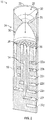
- the nozzle section 24 includes a converging portion 26, a throat portion 28 and a diverging portion 30 downstream of the throat portion 28, relative to a direction of fluid flow 32 into the flow distributor 18.
- the nozzle section 24 acts to accelerate the fluid flow 32 and break up a liquid portion of the two-phase fluid flow 32 into droplets of reduced size by the increased velocity of the gaseous portion of the two-phase fluid flow 32. Utilization of the nozzle section 24 to reduce the droplet size of the liquid portion of the fluid flow 32, allows for more uniformity and homogeneity of the two-phase fluid flow 32.
- the flow distributor 18 Downstream of the diverging portion 30, the flow distributor 18 includes a plurality of flow distribution passages 34 that each direct a portion of the fluid flow 32 to a flow outlet 22 of the plurality of flow outlets 22.
- Each flow distribution passage 34 has a distribution passage inlet 36 located at an inlet surface 38 downstream of the diverging portion 30.
- the flow distribution passages 34 are configured and arrayed to deliver a uniform two phase fluid flow 32 to each flow outlet 22, so that flow through the flow passages 12 is uniform. Uniformity may include an amount of liquid portion and gaseous portion in the two phase fluid flow 32, and may also refer to substantially equal flow rates and/or pressures of the fluid flow 32 through each of the flow passages 12.
- the distribution passage inlets 36 have a random distribution at the inlet surface 38.
- an embodiment of flow distributor 18 has seven flow outlets 22, each connected to and feeding one of seven flow passages 14.
- the embodiment includes 35 distribution passage inlets 36, with five distribution passage inlets 36 coupled to each of the seven flow outlets 22.
- the arrangement of the distribution passage inlets 36, relative to their connection to a particular flow outlet 22 is dispersed across the inlet surface 38, in an effort to improve the uniformity of the fluid flow 32 in the flow passages 12 relative to each other.
- distribution passage inlets 36a for example, are coupled to flow outlet 22a.
- distribution passages 34b are coupled to flow outlet 22b
- distribution passages 34c are coupled to flow outlet 22c
- distribution passages 34d are coupled to flow outlet 22d
- distribution passages 34e are coupled to flow outlet 22e
- distribution passages 34f are coupled to flow outlet 22f
- distribution passages 34g are coupled to flow outlet 22g, via their respective distribution passage inlets 36 located at inlet surface 38.
- the distribution passage inlets 36 are arrayed in a circular pattern with a distribution passage inlet 36 located at a center of the inlet surface 38, other patterns are contemplated within the scope of the present disclosure.
- the center distribution passage inlet 36 may be omitted, while in other embodiments, the distribution passage inlets 36 may be arrayed in, for example, an orthogonal grid pattern or other arrangement.
- five distribution passage inlets 36 are coupled to each flow outlet 22 in the present embodiment, in other embodiments different numbers of distribution passage inlets 36 may be utilized.
- the number of distribution passage inlets 36 coupled to the flow outlets 22 may be unequal, depending on, for example, flow requirements and locations of the distribution passage inlets 36 at the inlet surface 38. Further, the shape and/or size or orientation of the distribution passage inlets 36 may be varied to achieve the desired flow characteristics.
- FIGs. 4-10 shown are exemplary cross-sectional views of the flow distributor 18 taken at each flow outlet 22 of the embodiment of FIG. 3 .
- Each cross-sectional view illustrates a plenum 40 to connect the flow distribution passages 34 to the associated flow outlet 22.
- the plenums 40 are configured to envelop the flow distribution passages 34 connected to the associated flow outlet 22, with the plenum 40 acting as a flow distribution passage outlet.
- the flow distributor 18 is formed from a plurality of stacked layers 52, each layer 52 including a plenum 40 and a flow outlet 22.
- the layers 52 may be joined by welding or brazing or the like to form the flow distributor 18.
- the flow distributor may be formed by one or more additive manufacturing processes.
Landscapes
- Engineering & Computer Science (AREA)
- Physics & Mathematics (AREA)
- Mechanical Engineering (AREA)
- Thermal Sciences (AREA)
- General Engineering & Computer Science (AREA)
- Chemical & Material Sciences (AREA)
- Dispersion Chemistry (AREA)
- Chemical Kinetics & Catalysis (AREA)
- Details Of Heat-Exchange And Heat-Transfer (AREA)
- Heat-Exchange Devices With Radiators And Conduit Assemblies (AREA)
Abstract
Description
- The subject matter disclosed herein relates to fluid flow systems. More particularly, the present disclosure relates to distribution of two-phase flow in fluid flow systems.
- Non-uniform flow of the two-phase flow through the heat exchanger has a negative effect on the heat exchanger performance. Two phase flow, however, is inherently non-uniform, and achieving uniform two-phase flow to and through the many channels of a heat exchanger is typically very difficult. This is especially difficult when the heat exchanger channels are stacked vertically, and under the influence of gravity, the liquid phase has a tendency to proceed to the lowermost channels, with the gas phase collecting in the uppermost layers. Without uniform distribution of the two-phase flow, the system performance is reduced, which leads to increases in system size and complexity to achieve the desired performance. The increase in size increases system weight and cost.
- In one embodiment, a fluid distributor for a two-phase fluid flow system includes a distributor housing, a distributor inlet at the distributor housing to admit a two-phase fluid flow to the fluid distributor, a nozzle section through which the two-phase fluid flow is directed, a plurality of flow distribution passages located downstream of the nozzle section, and a plurality of passage outlets in the distributor housing. Each passage outlet of the plurality of passage outlets is coupled to one or more flow distribution passages. The plurality of flow distribution passages are configured and arrayed such that the two-phase flow through the plurality of passage outlets is uniform.
- Additionally or alternatively, in this or other embodiments a passage inlet surface is located downstream of the nozzle section. Each flow distribution passage has a passage inlet at the passage inlet surface.
- Additionally or alternatively, in this or other embodiments a plurality of passage inlets are dispersed across the passage inlet surface.
- Additionally or alternatively, in this or other embodiments a plurality of plenums are located in the housing. Each plenum is coupled to a passage outlet and at least one flow distribution passage.
- Additionally or alternatively, in this or other embodiments two or more flow distribution passages are coupled to the same plenum of the plurality of plenums.
- Additionally or alternatively, in this or other embodiments each flow distribution passage is coupled to only one passage outlet of the plurality of passage outlets.
- Additionally or alternatively, in this or other embodiments the nozzle section includes a converging portion, a throat portion downstream of the converging portion and a diverging portion downstream of the throat portion.
- Additionally or alternatively, in this or other embodiments the fluid distributor is formed via one or more additive manufacturing processes.
- In another embodiment, a two-phase fluid flow heat exchanger includes a plurality of heat exchange passages and a fluid distributor operably connected to the plurality of heat exchange passages. The distributor includes a distributor housing, a distributor inlet at the distributor housing to admit a two-phase fluid flow to the fluid distributor, a nozzle section through which the two-phase fluid flow is directed, a plurality of flow distribution passages located downstream of the nozzle section, and a plurality of passage outlets in the distributor housing. Each passage outlet of the plurality of passage outlets is coupled to one or more flow distribution passages and to a heat exchange passage of the plurality of heat exchange passages. The plurality of flow distribution passages are configured and arrayed such that the two-phase flow through the each of the heat exchange passages is uniform.
- Additionally or alternatively, in this or other embodiments a passage inlet surface is located downstream of the nozzle section. Each flow distribution passage has a passage inlet at the passage inlet surface.
- Additionally or alternatively, in this or other embodiments a plurality of passage inlets are dispersed across the passage inlet surface.
- Additionally or alternatively, in this or other embodiments a plurality of plenums are located in the housing. Each plenum is coupled to a passage outlet and at least one flow distribution passage.
- Additionally or alternatively, in this or other embodiments two or more flow distribution passages are coupled to the same plenum of the plurality of plenums.
- Additionally or alternatively, in this or other embodiments each flow distribution passage is coupled to only one passage outlet of the plurality of passage outlets.
- Additionally or alternatively, in this or other embodiments the nozzle section includes a converging portion, a throat portion downstream of the converging portion and a diverging portion downstream of the throat portion.
- The subject matter is particularly pointed out and distinctly claimed at the conclusion of the specification. The foregoing and other features, and advantages of the present disclosure are apparent from the following detailed description taken in conjunction with the accompanying drawings in which:
-
FIG. 1 is a schematic view of a heat exchanger system including an embodiment of a flow distributor; -
FIG. 2 is a cross-sectional view of an embodiment of a flow distributor; -
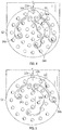
FIG. 3 is a cross-sectional view illustrating an exemplary array of flow distribution passage inlets for an embodiment of a flow distributor; and -
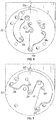
FIGs 4 - 10 illustrate exemplary cross-sectional views of an embodiment of a flow distributor. - Referring now to
FIG. 1 , illustrated is a partial cross-sectional view of a portion of a fluid flow system, for example, aheat exchanger 10. Theheat exchanger 10 includes a plurality offlow passages 12, through which a two-phase flow of, for example, a refrigerant, coolant or other fluid is directed. In the embodiment shown inFIG. 1 , theflow passages 12 are arranged in a vertical stack, with eachflow passage 12 having a passage inlet 14 and apassage outlet 16. Eachflow passage 12 extends substantially horizontally between itsrespective passage inlet 14 andpassage outlet 16. Aflow distributor 18 is connected to theflow passages 12 at eachpassage inlet 14 and extends vertically from anuppermost flow passage 12a tolowermost flow passage 12b, across one or moreintermediate flow passages 12c. It is to be appreciated that the arrangement shown inFIG. 1 is merely exemplary, and thatheat exchanger 10 is only one example of a type of fluid flow system in which theflow distributor 18 of the present disclosure may be utilized. Further, the arrangement of components shown inFIG. 1 and described herein is merely exemplary. For example, in some embodiments, theflow passages 12 may extend vertically between theirrespective passage inlet 14 andpassage outlet 16, with theflow distributor 18 extending horizontally across the plurality offlow passages 12. - Referring now to
FIG. 2 , a cross-sectional view of an embodiment of theflow distributor 18 is illustrated. Theflow distributor 18 has ahousing 50, with aflow inlet 20 located at thehousing 50, in this embodiment, at an upper extent of theflow distributor 18. Theflow distributor 18 also includes a plurality offlow outlets 22, eachflow outlet 22 connectable to a corresponding passage inlet 14 (shown inFIG. 1 ) of theheat exchanger 10. Proceeding from theflow inlet 20, in this embodiment downwardly from theflow inlet 20, theflow distributor 18 includes anozzle section 24. Thenozzle section 24 includes aconverging portion 26, athroat portion 28 and a divergingportion 30 downstream of thethroat portion 28, relative to a direction offluid flow 32 into theflow distributor 18. Thenozzle section 24 acts to accelerate thefluid flow 32 and break up a liquid portion of the two-phase fluid flow 32 into droplets of reduced size by the increased velocity of the gaseous portion of the two-phase fluid flow 32. Utilization of thenozzle section 24 to reduce the droplet size of the liquid portion of thefluid flow 32, allows for more uniformity and homogeneity of the two-phase fluid flow 32. - Downstream of the diverging
portion 30, theflow distributor 18 includes a plurality offlow distribution passages 34 that each direct a portion of thefluid flow 32 to aflow outlet 22 of the plurality offlow outlets 22. Eachflow distribution passage 34 has adistribution passage inlet 36 located at aninlet surface 38 downstream of the divergingportion 30. Theflow distribution passages 34 are configured and arrayed to deliver a uniform twophase fluid flow 32 to eachflow outlet 22, so that flow through theflow passages 12 is uniform. Uniformity may include an amount of liquid portion and gaseous portion in the twophase fluid flow 32, and may also refer to substantially equal flow rates and/or pressures of thefluid flow 32 through each of theflow passages 12. - To achieve this, referring now to
FIG. 3 , thedistribution passage inlets 36 have a random distribution at theinlet surface 38. For example, referring again toFIG. 1 , an embodiment offlow distributor 18 has sevenflow outlets 22, each connected to and feeding one of sevenflow passages 14. Referring again toFIG 3 , the embodiment includes 35distribution passage inlets 36, with fivedistribution passage inlets 36 coupled to each of the sevenflow outlets 22. As shown inFIG. 3 , the arrangement of thedistribution passage inlets 36, relative to their connection to aparticular flow outlet 22 is dispersed across theinlet surface 38, in an effort to improve the uniformity of thefluid flow 32 in theflow passages 12 relative to each other. In the embodiment ofFIG. 3 ,distribution passage inlets 36a, for example, are coupled to flowoutlet 22a. While shown better inFIGs. 4-10 ,distribution passages 34b are coupled to flowoutlet 22b,distribution passages 34c are coupled to flowoutlet 22c,distribution passages 34d are coupled to flowoutlet 22d,distribution passages 34e are coupled to flowoutlet 22e,distribution passages 34f are coupled to flowoutlet 22f, anddistribution passages 34g are coupled to flowoutlet 22g, via their respectivedistribution passage inlets 36 located atinlet surface 38. - While in the embodiment of
FIG. 3 , thedistribution passage inlets 36 are arrayed in a circular pattern with adistribution passage inlet 36 located at a center of theinlet surface 38, other patterns are contemplated within the scope of the present disclosure. For example, in some embodiments the centerdistribution passage inlet 36 may be omitted, while in other embodiments, thedistribution passage inlets 36 may be arrayed in, for example, an orthogonal grid pattern or other arrangement. Further, while fivedistribution passage inlets 36 are coupled to eachflow outlet 22 in the present embodiment, in other embodiments different numbers ofdistribution passage inlets 36 may be utilized. Additionally, in some embodiments, the number ofdistribution passage inlets 36 coupled to theflow outlets 22 may be unequal, depending on, for example, flow requirements and locations of thedistribution passage inlets 36 at theinlet surface 38. Further, the shape and/or size or orientation of thedistribution passage inlets 36 may be varied to achieve the desired flow characteristics. - Referring now to
FIGs. 4-10 , shown are exemplary cross-sectional views of theflow distributor 18 taken at eachflow outlet 22 of the embodiment ofFIG. 3 . Each cross-sectional view illustrates aplenum 40 to connect theflow distribution passages 34 to the associatedflow outlet 22. Theplenums 40 are configured to envelop theflow distribution passages 34 connected to the associatedflow outlet 22, with theplenum 40 acting as a flow distribution passage outlet. - In one embodiment, the
flow distributor 18 is formed from a plurality ofstacked layers 52, eachlayer 52 including aplenum 40 and aflow outlet 22. Thelayers 52 may be joined by welding or brazing or the like to form theflow distributor 18. In other embodiments. The flow distributor may be formed by one or more additive manufacturing processes. - While the present disclosure has been described in detail in connection with only a limited number of embodiments, it should be readily understood that the present disclosure is not limited to such disclosed embodiments. Rather, the present disclosure can be modified to incorporate any number of variations, alterations, substitutions or equivalent arrangements not heretofore described, but which are commensurate in spirit and/or scope. Additionally, while various embodiments have been described, it is to be understood that aspects of the present disclosure may include only some of the described embodiments. Accordingly, the present disclosure is not to be seen as limited by the foregoing description, but is only limited by the scope of the appended claims.
Claims (15)
- A fluid distributor (18) for a two-phase fluid flow system, comprising:a distributor housing (50);a distributor inlet (20) at the distributor housing (50) to admit a two-phase fluid flow to the fluid distributor (18);a nozzle section (24) through which the two-phase fluid flow is directed;a plurality of flow distribution passages (34) located downstream of the nozzle section (24); anda plurality of passage outlets (22) in the distributor housing (50), each passage outlet of the plurality of passage outlets coupled to one or more flow distribution passages, the plurality of flow distribution passages (34) configured and arrayed such that the two-phase flow through the plurality of passage outlets is uniform.
- The fluid distributor of claim 1, further comprising a passage inlet surface (38) located downstream of the nozzle section (24), each flow distribution passage (34) having a passage inlet (36) at the passage inlet surface (38).
- The fluid distributor of claim 2 wherein a plurality of passage inlets (36) are dispersed across the passage inlet surface (38).
- The fluid distributor of any preceding claim, further comprising a plurality of plenums (40) in the housing (50), each plenum (40) coupled to a passage outlet and at least one flow distribution passage (34).
- The fluid distributor of claim 4, wherein two or more flow distribution passages (34) are coupled to the same plenum (40) of the plurality of plenums.
- The fluid distributor of any preceding claim, wherein each flow distribution passage (34) is coupled to only one passage outlet (22) of the plurality of passage outlets (22).
- The fluid distributor of any preceding claim, wherein the nozzle section (24) includes a converging portion (26), a throat portion (28) downstream of the converging portion (26) and a diverging portion (30) downstream of the throat portion (28).
- The fluid distributor of any preceding claim, wherein the fluid distributor (18) is formed via one or more additive manufacturing processes.
- A two-phase fluid flow heat exchanger (10), comprising:a plurality of heat exchange passages (12); anda fluid distributor (18) operably connected to the plurality of heat exchange passages (12), including:a distributor housing (50);a distributor inlet (20) at the distributor housing (50) to admit a two-phase fluid flow to the fluid distributor (18);a nozzle section (24) through which the two-phase fluid flow is directed;a plurality of flow distribution passages (34) located downstream of the nozzle section (24); anda plurality of passage outlets (22) in the distributor housing (50), each passage outlet of the plurality of passage outlets coupled to one or more flow distribution passages (34) and to a heat exchange passage (12) of the plurality of heat exchange passages, the plurality of flow distribution passages (34) configured and arrayed such that the two-phase flow through the each of the heat exchange passages (34) is uniform.
- The heat exchanger of claim 9, further comprising a passage inlet surface (38) located downstream of the nozzle section (24), each flow distribution passage (34) having a passage inlet (36) at the passage inlet surface (38).
- The heat exchanger of claim 10, wherein a plurality of passage inlets (36) are dispersed across the passage inlet surface (38).
- The heat exchanger of claim 9, 10 or 11, further comprising a plurality of plenums (40) in the housing (50), each plenum coupled to a passage outlet (22) and at least one flow distribution passage (34).
- The heat exchanger of claim 12, wherein two or more flow distribution passages (34) are coupled to the same plenum (40) of the plurality of plenums.
- The heat exchanger of any of claims 9 to 13, wherein each flow distribution passage (34) is coupled to only one passage outlet (22) of the plurality of passage outlets (22).
- The heat exchanger of any of claims 9 to 14, wherein the nozzle section (24) includes a converging portion (26), a throat portion (28) downstream of the converging portion (26) and a diverging portion (30) downstream of the throat portion (28).
Applications Claiming Priority (1)
| Application Number | Priority Date | Filing Date | Title |
|---|---|---|---|
| US15/151,551 US20170328653A1 (en) | 2016-05-11 | 2016-05-11 | Flow distributor for two-phase flow |
Publications (2)
| Publication Number | Publication Date |
|---|---|
| EP3244139A1 true EP3244139A1 (en) | 2017-11-15 |
| EP3244139B1 EP3244139B1 (en) | 2020-04-08 |
Family
ID=59009495
Family Applications (1)
| Application Number | Title | Priority Date | Filing Date |
|---|---|---|---|
| EP17170676.5A Active EP3244139B1 (en) | 2016-05-11 | 2017-05-11 | Flow distributor for two-phase flow |
Country Status (2)
| Country | Link |
|---|---|
| US (1) | US20170328653A1 (en) |
| EP (1) | EP3244139B1 (en) |
Families Citing this family (11)
| Publication number | Priority date | Publication date | Assignee | Title |
|---|---|---|---|---|
| US20170191720A1 (en) * | 2016-01-05 | 2017-07-06 | General Electric Company | Air Conditioner Units Having Dehumidification Features |
| IT201800010006A1 (en) * | 2018-11-02 | 2020-05-02 | Sumitomo Riko Co Ltd | INTERNAL HEAT EXCHANGER |
| US11306971B2 (en) * | 2018-12-13 | 2022-04-19 | Applied Materials, Inc. | Heat exchanger with multistaged cooling |
| EP3855059B1 (en) * | 2020-01-24 | 2023-11-15 | Aptiv Technologies Limited | Passive flow divider and liquid cooling system comprising the same |
| JP2022099870A (en) * | 2020-12-23 | 2022-07-05 | 三星電子株式会社 | Refrigerant distributor and heat exchanger having refrigerant distributor |
| US12140326B2 (en) | 2020-12-23 | 2024-11-12 | Samsung Electronics Co., Ltd. | Heat exchanger and air conditioner including the same |
| US11976677B2 (en) | 2021-11-05 | 2024-05-07 | Hamilton Sundstrand Corporation | Integrally formed flow distributor for fluid manifold |
| US12209823B2 (en) * | 2022-01-21 | 2025-01-28 | Hamilton Sundstrand Corporation | Heat exchanger header structures |
| WO2023153309A1 (en) * | 2022-02-09 | 2023-08-17 | 三菱電機株式会社 | Refrigerant distributor, heat exchanger, and refrigeration cycle device |
| CN115751783A (en) * | 2022-11-18 | 2023-03-07 | 青岛海尔空调器有限总公司 | Liquid separator, method for determining porosity of partition plate in liquid separator and air conditioning system |
| US12281593B1 (en) * | 2024-03-27 | 2025-04-22 | Chromalloy Gas Turbine Llc | Fluid flow distributor for vapor phase coating of turbine components |
Citations (6)
| Publication number | Priority date | Publication date | Assignee | Title |
|---|---|---|---|---|
| US2099186A (en) * | 1935-12-24 | 1937-11-16 | Reuben H Anderegg | Evaporator coil |
| DE7427716U (en) * | 1974-11-21 | Wieland Werke Ag | Device for the distribution of liquid-vapor mixtures in injection evaporators | |
| JPH0527568U (en) * | 1991-09-26 | 1993-04-09 | 三菱重工業株式会社 | Gas-liquid two-phase flow distributor |
| JPH06229651A (en) * | 1993-02-04 | 1994-08-19 | Mitsubishi Heavy Ind Ltd | Distributor for two-phase fluid of gas and liquid |
| JPH06347136A (en) * | 1993-06-10 | 1994-12-20 | Mitsubishi Heavy Ind Ltd | Distributor for mixed phase fluid |
| EP2806244A1 (en) * | 2013-05-23 | 2014-11-26 | Hamilton Sundstrand Corporation | Heat exchanger distribution assembly and method |
Family Cites Families (14)
| Publication number | Priority date | Publication date | Assignee | Title |
|---|---|---|---|---|
| US266680A (en) * | 1882-10-31 | Liquid-distributer for refrig eratin g - m ac h in es | ||
| US2044455A (en) * | 1935-05-16 | 1936-06-16 | Young Radiator Co | Distributing head for evaporators |
| US2803116A (en) * | 1954-08-02 | 1957-08-20 | Alco Valve Co | Refrigerant distributor |
| US2787138A (en) * | 1955-04-18 | 1957-04-02 | Betz Corp | Fluid mixing device |
| US3151676A (en) * | 1961-08-17 | 1964-10-06 | United Aircraft Prod | Distributor head for heat exchangers |
| US4513587A (en) * | 1981-09-14 | 1985-04-30 | Sueddeutsche Kuehlerfabrik Julius Fr. Behr Gmbh & Co., Kg | Evaporator particularly suitable for air conditioners in automotive vehicles |
| US5243838A (en) * | 1989-08-18 | 1993-09-14 | Matsushita Refrigeration Company | Refrigerant shunt |
| JP3217547B2 (en) * | 1993-06-10 | 2001-10-09 | 三菱重工業株式会社 | Multi-phase fluid distributor |
| US5682759A (en) * | 1996-02-27 | 1997-11-04 | Hays; Lance Gregory | Two phase nozzle equipped with flow divider |
| JPH09257386A (en) * | 1996-03-22 | 1997-10-03 | Sanden Corp | Distributor and heat exchanger equipped with it |
| JP3705859B2 (en) * | 1996-03-29 | 2005-10-12 | サンデン株式会社 | Heat exchanger with distribution device |
| US6892805B1 (en) * | 2004-04-05 | 2005-05-17 | Modine Manufacturing Company | Fluid flow distribution device |
| KR100913141B1 (en) * | 2004-09-15 | 2009-08-19 | 삼성전자주식회사 | Evaporator Using Microchannel Tube |
| US20060266502A1 (en) * | 2005-05-24 | 2006-11-30 | Saman Inc. | Multi-flow condenser for air conditioning systems |
-
2016
- 2016-05-11 US US15/151,551 patent/US20170328653A1/en not_active Abandoned
-
2017
- 2017-05-11 EP EP17170676.5A patent/EP3244139B1/en active Active
Patent Citations (6)
| Publication number | Priority date | Publication date | Assignee | Title |
|---|---|---|---|---|
| DE7427716U (en) * | 1974-11-21 | Wieland Werke Ag | Device for the distribution of liquid-vapor mixtures in injection evaporators | |
| US2099186A (en) * | 1935-12-24 | 1937-11-16 | Reuben H Anderegg | Evaporator coil |
| JPH0527568U (en) * | 1991-09-26 | 1993-04-09 | 三菱重工業株式会社 | Gas-liquid two-phase flow distributor |
| JPH06229651A (en) * | 1993-02-04 | 1994-08-19 | Mitsubishi Heavy Ind Ltd | Distributor for two-phase fluid of gas and liquid |
| JPH06347136A (en) * | 1993-06-10 | 1994-12-20 | Mitsubishi Heavy Ind Ltd | Distributor for mixed phase fluid |
| EP2806244A1 (en) * | 2013-05-23 | 2014-11-26 | Hamilton Sundstrand Corporation | Heat exchanger distribution assembly and method |
Also Published As
| Publication number | Publication date |
|---|---|
| EP3244139B1 (en) | 2020-04-08 |
| US20170328653A1 (en) | 2017-11-16 |
Similar Documents
| Publication | Publication Date | Title |
|---|---|---|
| EP3244139B1 (en) | Flow distributor for two-phase flow | |
| US20150136366A1 (en) | Heat exchanger | |
| CN107667265B (en) | Multi-stage distribution system for evaporators | |
| EP2853843B1 (en) | A refrigerant distributing device, and heat exchanger equipped with such a refrigerant distributing device | |
| US20160234967A1 (en) | Heat Management and Removal Assemblies for Semiconductor Devices | |
| US20150083383A1 (en) | Heat exchanger and heat exchange method | |
| CN104380023B (en) | Heat-exchangers of the plate type with injection apparatus | |
| KR102143370B1 (en) | Condensing and Falling Film Evaporative Hybrid Heat Exchanger | |
| JP2015196839A (en) | Gas supply pipe and gas treatment apparatus | |
| US20140360601A1 (en) | Upper electrode device | |
| CN104380022B (en) | A plate heat exchanger | |
| JP5306279B2 (en) | Refrigerant distributor and evaporator | |
| US20220268532A1 (en) | Heat exchanger | |
| US9206708B2 (en) | Direct contact condenser for a steam turbine and having a first cooling water spraying mechanism spraying cooling water downstream and a second cooling water spraying mechanism spraying cooling water in multiple directions | |
| CN105783347A (en) | Refrigerant distributor for falling film evaporator | |
| JP2015092120A (en) | Condenser | |
| US20240401852A1 (en) | Falling film evaporator | |
| EP3077756B1 (en) | Asymmetric evaporator | |
| JP2013050221A (en) | Refrigerant distributor and heat pump apparatus using the same | |
| JPWO2021245901A5 (en) | ||
| CN214620813U (en) | Dispenser | |
| US20180149062A1 (en) | Heat exchanger for a motor vehicle | |
| CN110966808B (en) | Microchannel heat exchanger and refrigerating system | |
| CN210718232U (en) | Flow distribution orifice plate and distributor | |
| CN114396743A (en) | A liquid distributor for a falling film heat exchanger |
Legal Events
| Date | Code | Title | Description |
|---|---|---|---|
| PUAI | Public reference made under article 153(3) epc to a published international application that has entered the european phase |
Free format text: ORIGINAL CODE: 0009012 |
|
| STAA | Information on the status of an ep patent application or granted ep patent |
Free format text: STATUS: THE APPLICATION HAS BEEN PUBLISHED |
|
| AK | Designated contracting states |
Kind code of ref document: A1 Designated state(s): AL AT BE BG CH CY CZ DE DK EE ES FI FR GB GR HR HU IE IS IT LI LT LU LV MC MK MT NL NO PL PT RO RS SE SI SK SM TR |
|
| AX | Request for extension of the european patent |
Extension state: BA ME |
|
| STAA | Information on the status of an ep patent application or granted ep patent |
Free format text: STATUS: REQUEST FOR EXAMINATION WAS MADE |
|
| 17P | Request for examination filed |
Effective date: 20180515 |
|
| RBV | Designated contracting states (corrected) |
Designated state(s): AL AT BE BG CH CY CZ DE DK EE ES FI FR GB GR HR HU IE IS IT LI LT LU LV MC MK MT NL NO PL PT RO RS SE SI SK SM TR |
|
| STAA | Information on the status of an ep patent application or granted ep patent |
Free format text: STATUS: EXAMINATION IS IN PROGRESS |
|
| 17Q | First examination report despatched |
Effective date: 20180713 |
|
| GRAP | Despatch of communication of intention to grant a patent |
Free format text: ORIGINAL CODE: EPIDOSNIGR1 |
|
| RIC1 | Information provided on ipc code assigned before grant |
Ipc: F25B 39/00 20060101AFI20190920BHEP Ipc: F25B 39/02 20060101ALN20190920BHEP |
|
| STAA | Information on the status of an ep patent application or granted ep patent |
Free format text: STATUS: GRANT OF PATENT IS INTENDED |
|
| RIC1 | Information provided on ipc code assigned before grant |
Ipc: F25B 39/00 20060101AFI20191008BHEP Ipc: F25B 39/02 20060101ALN20191008BHEP |
|
| INTG | Intention to grant announced |
Effective date: 20191031 |
|
| GRAS | Grant fee paid |
Free format text: ORIGINAL CODE: EPIDOSNIGR3 |
|
| GRAA | (expected) grant |
Free format text: ORIGINAL CODE: 0009210 |
|
| STAA | Information on the status of an ep patent application or granted ep patent |
Free format text: STATUS: THE PATENT HAS BEEN GRANTED |
|
| AK | Designated contracting states |
Kind code of ref document: B1 Designated state(s): AL AT BE BG CH CY CZ DE DK EE ES FI FR GB GR HR HU IE IS IT LI LT LU LV MC MK MT NL NO PL PT RO RS SE SI SK SM TR |
|
| REG | Reference to a national code |
Ref country code: CH Ref legal event code: EP Ref country code: AT Ref legal event code: REF Ref document number: 1254933 Country of ref document: AT Kind code of ref document: T Effective date: 20200415 |
|
| REG | Reference to a national code |
Ref country code: DE Ref legal event code: R096 Ref document number: 602017014218 Country of ref document: DE |
|
| REG | Reference to a national code |
Ref country code: IE Ref legal event code: FG4D |
|
| REG | Reference to a national code |
Ref country code: NL Ref legal event code: MP Effective date: 20200408 |
|
| REG | Reference to a national code |
Ref country code: LT Ref legal event code: MG4D |
|
| PG25 | Lapsed in a contracting state [announced via postgrant information from national office to epo] |
Ref country code: NO Free format text: LAPSE BECAUSE OF FAILURE TO SUBMIT A TRANSLATION OF THE DESCRIPTION OR TO PAY THE FEE WITHIN THE PRESCRIBED TIME-LIMIT Effective date: 20200708 Ref country code: GR Free format text: LAPSE BECAUSE OF FAILURE TO SUBMIT A TRANSLATION OF THE DESCRIPTION OR TO PAY THE FEE WITHIN THE PRESCRIBED TIME-LIMIT Effective date: 20200709 Ref country code: PT Free format text: LAPSE BECAUSE OF FAILURE TO SUBMIT A TRANSLATION OF THE DESCRIPTION OR TO PAY THE FEE WITHIN THE PRESCRIBED TIME-LIMIT Effective date: 20200817 Ref country code: LT Free format text: LAPSE BECAUSE OF FAILURE TO SUBMIT A TRANSLATION OF THE DESCRIPTION OR TO PAY THE FEE WITHIN THE PRESCRIBED TIME-LIMIT Effective date: 20200408 Ref country code: NL Free format text: LAPSE BECAUSE OF FAILURE TO SUBMIT A TRANSLATION OF THE DESCRIPTION OR TO PAY THE FEE WITHIN THE PRESCRIBED TIME-LIMIT Effective date: 20200408 Ref country code: SE Free format text: LAPSE BECAUSE OF FAILURE TO SUBMIT A TRANSLATION OF THE DESCRIPTION OR TO PAY THE FEE WITHIN THE PRESCRIBED TIME-LIMIT Effective date: 20200408 Ref country code: IS Free format text: LAPSE BECAUSE OF FAILURE TO SUBMIT A TRANSLATION OF THE DESCRIPTION OR TO PAY THE FEE WITHIN THE PRESCRIBED TIME-LIMIT Effective date: 20200808 Ref country code: FI Free format text: LAPSE BECAUSE OF FAILURE TO SUBMIT A TRANSLATION OF THE DESCRIPTION OR TO PAY THE FEE WITHIN THE PRESCRIBED TIME-LIMIT Effective date: 20200408 |
|
| REG | Reference to a national code |
Ref country code: AT Ref legal event code: MK05 Ref document number: 1254933 Country of ref document: AT Kind code of ref document: T Effective date: 20200408 |
|
| PG25 | Lapsed in a contracting state [announced via postgrant information from national office to epo] |
Ref country code: RS Free format text: LAPSE BECAUSE OF FAILURE TO SUBMIT A TRANSLATION OF THE DESCRIPTION OR TO PAY THE FEE WITHIN THE PRESCRIBED TIME-LIMIT Effective date: 20200408 Ref country code: HR Free format text: LAPSE BECAUSE OF FAILURE TO SUBMIT A TRANSLATION OF THE DESCRIPTION OR TO PAY THE FEE WITHIN THE PRESCRIBED TIME-LIMIT Effective date: 20200408 Ref country code: LV Free format text: LAPSE BECAUSE OF FAILURE TO SUBMIT A TRANSLATION OF THE DESCRIPTION OR TO PAY THE FEE WITHIN THE PRESCRIBED TIME-LIMIT Effective date: 20200408 Ref country code: BG Free format text: LAPSE BECAUSE OF FAILURE TO SUBMIT A TRANSLATION OF THE DESCRIPTION OR TO PAY THE FEE WITHIN THE PRESCRIBED TIME-LIMIT Effective date: 20200708 |
|
| PG25 | Lapsed in a contracting state [announced via postgrant information from national office to epo] |
Ref country code: AL Free format text: LAPSE BECAUSE OF FAILURE TO SUBMIT A TRANSLATION OF THE DESCRIPTION OR TO PAY THE FEE WITHIN THE PRESCRIBED TIME-LIMIT Effective date: 20200408 |
|
| REG | Reference to a national code |
Ref country code: DE Ref legal event code: R097 Ref document number: 602017014218 Country of ref document: DE |
|
| PG25 | Lapsed in a contracting state [announced via postgrant information from national office to epo] |
Ref country code: LI Free format text: LAPSE BECAUSE OF NON-PAYMENT OF DUE FEES Effective date: 20200531 Ref country code: MC Free format text: LAPSE BECAUSE OF FAILURE TO SUBMIT A TRANSLATION OF THE DESCRIPTION OR TO PAY THE FEE WITHIN THE PRESCRIBED TIME-LIMIT Effective date: 20200408 Ref country code: RO Free format text: LAPSE BECAUSE OF FAILURE TO SUBMIT A TRANSLATION OF THE DESCRIPTION OR TO PAY THE FEE WITHIN THE PRESCRIBED TIME-LIMIT Effective date: 20200408 Ref country code: CZ Free format text: LAPSE BECAUSE OF FAILURE TO SUBMIT A TRANSLATION OF THE DESCRIPTION OR TO PAY THE FEE WITHIN THE PRESCRIBED TIME-LIMIT Effective date: 20200408 Ref country code: ES Free format text: LAPSE BECAUSE OF FAILURE TO SUBMIT A TRANSLATION OF THE DESCRIPTION OR TO PAY THE FEE WITHIN THE PRESCRIBED TIME-LIMIT Effective date: 20200408 Ref country code: SM Free format text: LAPSE BECAUSE OF FAILURE TO SUBMIT A TRANSLATION OF THE DESCRIPTION OR TO PAY THE FEE WITHIN THE PRESCRIBED TIME-LIMIT Effective date: 20200408 Ref country code: EE Free format text: LAPSE BECAUSE OF FAILURE TO SUBMIT A TRANSLATION OF THE DESCRIPTION OR TO PAY THE FEE WITHIN THE PRESCRIBED TIME-LIMIT Effective date: 20200408 Ref country code: CH Free format text: LAPSE BECAUSE OF NON-PAYMENT OF DUE FEES Effective date: 20200531 Ref country code: AT Free format text: LAPSE BECAUSE OF FAILURE TO SUBMIT A TRANSLATION OF THE DESCRIPTION OR TO PAY THE FEE WITHIN THE PRESCRIBED TIME-LIMIT Effective date: 20200408 Ref country code: IT Free format text: LAPSE BECAUSE OF FAILURE TO SUBMIT A TRANSLATION OF THE DESCRIPTION OR TO PAY THE FEE WITHIN THE PRESCRIBED TIME-LIMIT Effective date: 20200408 Ref country code: DK Free format text: LAPSE BECAUSE OF FAILURE TO SUBMIT A TRANSLATION OF THE DESCRIPTION OR TO PAY THE FEE WITHIN THE PRESCRIBED TIME-LIMIT Effective date: 20200408 |
|
| PLBE | No opposition filed within time limit |
Free format text: ORIGINAL CODE: 0009261 |
|
| STAA | Information on the status of an ep patent application or granted ep patent |
Free format text: STATUS: NO OPPOSITION FILED WITHIN TIME LIMIT |
|
| PG25 | Lapsed in a contracting state [announced via postgrant information from national office to epo] |
Ref country code: SK Free format text: LAPSE BECAUSE OF FAILURE TO SUBMIT A TRANSLATION OF THE DESCRIPTION OR TO PAY THE FEE WITHIN THE PRESCRIBED TIME-LIMIT Effective date: 20200408 Ref country code: PL Free format text: LAPSE BECAUSE OF FAILURE TO SUBMIT A TRANSLATION OF THE DESCRIPTION OR TO PAY THE FEE WITHIN THE PRESCRIBED TIME-LIMIT Effective date: 20200408 |
|
| 26N | No opposition filed |
Effective date: 20210112 |
|
| REG | Reference to a national code |
Ref country code: BE Ref legal event code: MM Effective date: 20200531 |
|
| PG25 | Lapsed in a contracting state [announced via postgrant information from national office to epo] |
Ref country code: LU Free format text: LAPSE BECAUSE OF NON-PAYMENT OF DUE FEES Effective date: 20200511 |
|
| PG25 | Lapsed in a contracting state [announced via postgrant information from national office to epo] |
Ref country code: IE Free format text: LAPSE BECAUSE OF NON-PAYMENT OF DUE FEES Effective date: 20200511 |
|
| PG25 | Lapsed in a contracting state [announced via postgrant information from national office to epo] |
Ref country code: BE Free format text: LAPSE BECAUSE OF NON-PAYMENT OF DUE FEES Effective date: 20200531 Ref country code: SI Free format text: LAPSE BECAUSE OF FAILURE TO SUBMIT A TRANSLATION OF THE DESCRIPTION OR TO PAY THE FEE WITHIN THE PRESCRIBED TIME-LIMIT Effective date: 20200408 |
|
| PG25 | Lapsed in a contracting state [announced via postgrant information from national office to epo] |
Ref country code: TR Free format text: LAPSE BECAUSE OF FAILURE TO SUBMIT A TRANSLATION OF THE DESCRIPTION OR TO PAY THE FEE WITHIN THE PRESCRIBED TIME-LIMIT Effective date: 20200408 Ref country code: MT Free format text: LAPSE BECAUSE OF FAILURE TO SUBMIT A TRANSLATION OF THE DESCRIPTION OR TO PAY THE FEE WITHIN THE PRESCRIBED TIME-LIMIT Effective date: 20200408 Ref country code: CY Free format text: LAPSE BECAUSE OF FAILURE TO SUBMIT A TRANSLATION OF THE DESCRIPTION OR TO PAY THE FEE WITHIN THE PRESCRIBED TIME-LIMIT Effective date: 20200408 |
|
| PG25 | Lapsed in a contracting state [announced via postgrant information from national office to epo] |
Ref country code: MK Free format text: LAPSE BECAUSE OF FAILURE TO SUBMIT A TRANSLATION OF THE DESCRIPTION OR TO PAY THE FEE WITHIN THE PRESCRIBED TIME-LIMIT Effective date: 20200408 |
|
| P01 | Opt-out of the competence of the unified patent court (upc) registered |
Effective date: 20230522 |
|
| PGFP | Annual fee paid to national office [announced via postgrant information from national office to epo] |
Ref country code: DE Payment date: 20250423 Year of fee payment: 9 |
|
| PGFP | Annual fee paid to national office [announced via postgrant information from national office to epo] |
Ref country code: GB Payment date: 20250423 Year of fee payment: 9 |
|
| PGFP | Annual fee paid to national office [announced via postgrant information from national office to epo] |
Ref country code: FR Payment date: 20250423 Year of fee payment: 9 |