EP3244108A1 - Check valves - Google Patents
Check valves Download PDFInfo
- Publication number
- EP3244108A1 EP3244108A1 EP16461521.3A EP16461521A EP3244108A1 EP 3244108 A1 EP3244108 A1 EP 3244108A1 EP 16461521 A EP16461521 A EP 16461521A EP 3244108 A1 EP3244108 A1 EP 3244108A1
- Authority
- EP
- European Patent Office
- Prior art keywords
- check valve
- vanes
- valve
- rotary element
- windows
- Prior art date
- Legal status (The legal status is an assumption and is not a legal conclusion. Google has not performed a legal analysis and makes no representation as to the accuracy of the status listed.)
- Granted
Links
Images


Classifications
-
- F—MECHANICAL ENGINEERING; LIGHTING; HEATING; WEAPONS; BLASTING
- F16—ENGINEERING ELEMENTS AND UNITS; GENERAL MEASURES FOR PRODUCING AND MAINTAINING EFFECTIVE FUNCTIONING OF MACHINES OR INSTALLATIONS; THERMAL INSULATION IN GENERAL
- F16K—VALVES; TAPS; COCKS; ACTUATING-FLOATS; DEVICES FOR VENTING OR AERATING
- F16K15/00—Check valves
- F16K15/02—Check valves with guided rigid valve members
- F16K15/021—Check valves with guided rigid valve members the valve member being a movable body around which the medium flows when the valve is open
-
- F—MECHANICAL ENGINEERING; LIGHTING; HEATING; WEAPONS; BLASTING
- F16—ENGINEERING ELEMENTS AND UNITS; GENERAL MEASURES FOR PRODUCING AND MAINTAINING EFFECTIVE FUNCTIONING OF MACHINES OR INSTALLATIONS; THERMAL INSULATION IN GENERAL
- F16K—VALVES; TAPS; COCKS; ACTUATING-FLOATS; DEVICES FOR VENTING OR AERATING
- F16K15/00—Check valves
-
- F—MECHANICAL ENGINEERING; LIGHTING; HEATING; WEAPONS; BLASTING
- F16—ENGINEERING ELEMENTS AND UNITS; GENERAL MEASURES FOR PRODUCING AND MAINTAINING EFFECTIVE FUNCTIONING OF MACHINES OR INSTALLATIONS; THERMAL INSULATION IN GENERAL
- F16K—VALVES; TAPS; COCKS; ACTUATING-FLOATS; DEVICES FOR VENTING OR AERATING
- F16K31/00—Actuating devices; Operating means; Releasing devices
- F16K31/12—Actuating devices; Operating means; Releasing devices actuated by fluid
Definitions
- the present disclosure relates to check valves.
- check valves It is known to use check valves to allow fluid flow in one direction therethrough, and to prevent flow in the opposite direction.
- Check valves are widely used in a wide variety of applications, for example in air conditioning systems, for example in aircraft air conditioning systems.
- check valve includes a pair of hinged flappers that pivot open in the direction of fluid flow when the fluid pressure differential exceeds a predetermined valve "cracking pressure". If a negative pressure differential exists across the valve, the flapper elements close, preventing flow reversal.
- Such check valves typically include a pair of flapper elements and frequently employ stops or bumpers which restrict the opening movement of the flapper element past a predetermined maximum opening angle.
- Such a check valve is disclosed in, for example, GB 2514953 .
- the flapper elements When the cracking pressure is exceeded the flapper elements may open at high speed. When they subsequently cooperate with the stops/bumpers high stresses may be generated. This may lead to reduced part life and increased maintenance costs.
- the check valve comprises a valve plate comprising a plurality of openings therethrough and a shroud extending from the valve plate around each of the openings.
- the shroud and the valve plate define an at least partially circumferentially facing window.
- the check valve also comprises a rotary element rotatably mounted to the valve plate about a rotational axis.
- the rotary element comprises a plurality of radially extending vanes and is mounted such that each vane is positioned between two adjacent shrouds.
- the vanes are angled such that fluid flow incident thereon in a direction parallel to said rotational axis will rotate the rotary element about the rotational axis.
- the rotary element is rotatable between an open position in which the vanes are spaced circumferentially from the windows to allow fluid to flow through the windows via the openings, and a closed position in which the vanes close the windows, thereby preventing fluid flow therethrough.
- a lower portion of the window is defined by a lip upstanding from the valve plate. Additionally, the lip may have a profile complementary to that of the vane to create an area contact therebetween.
- the vanes engage around the respective edges of the windows to close the windows.
- a sealing element may be provided around the edges of each window, and the sealing element may be resilient.
- each shroud comprises a bumper surface configured to contact a respective vane along a length thereof in the open position.
- the bumper surface may have a profile complementary to that of the vane to create an area contact therebetween.
- the bumper surface may comprise a separate bumper element.
- the vanes rotate about the rotational axis between the closed and open valve positions through an angle of between 10° and 20°, more narrowly 14° to 18°, for example, 16°.
- valve plate comprises between 10 and 16 openings and the rotary element comprises the same number of vanes.
- valve plate comprises 12 openings and the rotary element comprises 12 vanes.
- the vanes have an airfoil cross-section.
- the vanes feature a twist along their radial axis.
- the rotary element is rotatably mounted onto a shaft extending from the valve plate.
- Check valve 2 is configured to be mounted around its periphery in or to, for example, a duct in order to prevent reverse flow of a fluid through the duct.
- the check valve 2 comprises a static, generally circular valve plate 10 and a rotary element 20, which is rotatably mounted to the valve plate 10 about rotational axis R.
- the valve plate 10 may be of any shape.
- valve plate 10 comprises a shaft 15 that extends along rotational axis R and rotary element 20 comprises a bore 25 through the central hub 24 that fits over shaft 15 to allow rotary element 20 to be mounted rotatably to valve plate 10.
- a bearing (not shown) may be mounted around the shaft 15 and the bore 25 to allow rotation of the rotary element 20 around the shaft 15.
- any other suitable means of providing rotatable mounting of the rotary element 20 to the valve plate 10 as would be understood by one skilled in the art, may be used within the scope of this disclosure.
- the valve plate 10 comprises a plurality of openings 13 therethrough.
- the openings 13 are generally triangular or trapezoidal in shape, however, any shape opening may be used within the scope of this disclosure.
- the valve plate 10 also comprises shrouds 12 that extend upwardly from the valve plate 10 and around each opening 13.
- the shrouds 12 and the valve plate 10 define windows 14.
- Windows 14 face in at least partially a circumferential direction.
- shrouds 12 are shaped such that portions of the windows 14 face in radial and axial (i.e. in the direction of the rotational axis R) directions, in addition to the circumferential direction.
- the windows 14 may only face the circumferential direction.
- valve plate 10 does not comprise such lips 16. The function of the lips 16 is described below in relation to the closing of the check valve 2.
- the edges of windows 14 comprise a sealing element 19 thereon, which aids closing of the check valve 2 (as described in more detail below).
- Sealing element 19 may be a resilient and/or compliant material. In alternative embodiments, however, the edges of windows 14 do not comprise an additional sealing element 19.
- Bumper surfaces 18 are formed on or associated with a rear surface 17 of shrouds 12. Bumper surfaces 18 are configured to contact a respective vane 22 along a length thereof, as will be described in more detail below in relation to the opening of the check valve 2. As shown in Figures 1 to 5 , the rear surface 17 of shrouds 12 at least partially faces the circumferential direction (i.e. the rear surfaces 17 are the back surfaces on the body of the shrouds 12, opposite the windows 14). In the depicted embodiment, the bumper surface 18 comprises a separate bumper element attached to the rear surface of the shroud 12, however, in alternative embodiments, bumper surface 18 is just a specific area of the rear surface 17 of the shroud 12 that contacts a length of vanes 22 in the open position.
- the rotary element 20 has a plurality of vanes 22 that extend radially from a central hub 24.
- the vanes 22 extend across the valve plate 10, in between adjacent shrouds 12, and have a leading edge 26 that faces the valve plate 10 surface and is separated by a small gap therefrom.
- the leading edge 26 may be in loose contact with the valve plate 10, as discussed in more detail below.
- vanes 22 there are the same number of vanes 22 as windows 14 (and also shrouds 12 and openings 13).
- the vanes 22 are angled relative to the rotational axis R, such that when fluid flow is incident on the vanes 22 in a direction parallel to the rotational axis R the rotary element 20 is forced to rotate.
- the check valve 2 has a forward side and a backward side.
- the backward side is the side of the check valve 2 into which shrouds 12 extend, whereas the forward side is the opposite side to the backward side.
- the check valve 2 can encounter fluid flow in a positive (i.e. forward) flow direction or a negative (i.e. reverse) direction.
- positive flow direction fluid passes from the forward side to backward side, through the openings 13 and windows 14, whereas in the negative flow direction, fluid attempts to pass from the backward side to the forward side through the windows 14 and openings 13.
- each vane 22 When there is a positive flow differential across the check valve 2, fluid will flow in the positive flow direction and exit the valve 2 through windows 14. The fluid will be directed onto vanes 22 causing the rotary element 20 to rotate into an open position, which permits further fluid flow through the valve 2. As shown in Figure 3 , when fully open, a length of each vane 22 will be forced into contact with respective bumper surface 18. Rotation to this position causes the vanes 22 to exert a force on the bumper surfaces 18.
- the bumper surface 18 has a profile which is complementary to that of the vane 22 such that there is contact between them over an area rather than a line contact.
- the vanes 22 are sized and shaped to completely cover windows 14.
- the windows 14 and lips 16 are also contoured to complement the shape and profile of the vanes 22.
- Sealing elements 19 also act to aid sealing between the vanes 22 and the windows 14.
- FIGS 1 to 4 and 6 show vanes 22 having an airfoil cross-section, however, it is to be understood that vanes 22 may also be planar or have any other suitable cross-section, as would be apparent to one skilled in the art. In addition, vanes 22 may also comprise other characteristics such as a twist along their length (i.e. along their radial axis).
- varying the vane 22 cross-section and characteristics may be used to tailor the force required to rotate the rotary element 20 to provide a certain cracking pressure (i.e. minimum force necessary for the valve 2 to rotate from a closed to an open position) or to change the valve's response time between opening and closing. It may also be used to tailor the amount of force that the vanes 22 exert on the windows 14, lips 16, sealing elements 19 and bumper surfaces 18, during opening and closing of the valve.
- a biasing element may be used to bias the check valve 2 to a closed position.
- the biasing member may also be used to increase the cracking pressure of the check valve 2.
- the biasing member could be a spring attached between the shrouds 12 and the vanes 22, a spring attached between the hub 24 and shaft 15 or another means that inhibits the rotation of the rotary element 20 from the closed position to the open position.
- leading edge 26 is positioned above the valve plate 10 surface. In this way, the leading edge 26 and valve plate 10 do not contact each other as the vanes 22 rotate over the valve plate 10, minimising friction therebetween. However, in alternative embodiments, the leading edge 26 is in loose contact with the valve plate 10 surface. This aims to minimise fluid leakage between the leading edge 26 and the valve plate 10, without generating unacceptable friction or wear.
- openings 13 there are twelve openings 13 (and corresponding numbers of vanes 22 and shrouds 12) shown, however, it should be understood that only two or more openings (and corresponding numbers of vanes 22 and shrouds 12) are necessary for the check valve 2 to operate. It is believed that fewer openings 13 may increase the pressure drop across the check valve 2. However, as explained below, fewer openings 13 also increases the impact forces exerted by the vanes 22 on the windows 14, lips 16, sealing elements 19 and bumper surfaces 18. As will be understood by one skilled in the art, this trade-off can be used to tailor the number of openings 13 to the given application of the check valve 2. In certain embodiments, a suitable number of openings 13 is between 10 and 18.
- the openings 13 and windows 14 are sized to allow sufficient fluid flow therethrough for the application at hand.
- the openings 13 and windows 14 may therefore be sized to have an area that is any percentage of the total valve plate 10 area, as a given application requires.
- angular rotation rotary element 20 dictates how much angular rotation rotary element 20 may undergo about rotational axis R between the open and closed positions.
- a lower angular rotation angle ⁇ decreases the impact forces exerted by the vanes 22 on the windows 14, lips 16 and bumper surfaces 18 when the valve 2 rotates to the closed and open positions.
- the number, size and spacing of the openings and the corresponding number of vanes 22 can be varied to reduce or increase the impact force as desired.
- any angular rotation angle between 0° ⁇ ⁇ ⁇ 180° can be used, within the scope of this disclosure.
- Lips 16 and sealing elements 19 may also act as areas of reinforcement for windows 14, which aids the absorption of stress exerted on the windows 14.
- Bumper surfaces 18 may also act to reinforce the shrouds 12 and protect them from the force exerted on them by the vanes 22 rotating to the open position.
- the valve plate 10 and rotary element 20 may be made of a metallic material, a plastic material or a composite material, as a given application or working environment requires. For instance, they may be made of aluminium, titanium, steel or an alloy thereof. They may alternatively be made of an Ni-based alloy. Depending on the application of the check valve 2, they may be corrosion resistant or have a corrosion resistant coating applied thereto. In addition or alternatively, they may also have a heat resistant coating applied thereto.
- valve plate 10 and rotary element 20 may be additively manufactured or subtractively manufactured (e.g. machined). Alternatively, they may be cast.
- shrouds 12 and shaft 15 may be integrally formed as part of the valve plate 10 or may be produced as separate components and coupled thereto.
- the vanes 22 may be integrally formed as part of the rotary element 20, or may be separate components coupled thereto.
- Lips 16, sealing elements 19 and bumper surfaces 18 may be separate components from the valve plate 10 and coupled thereto, or alternatively, may be integrally formed as part of the valve plate 10.
- the lips 16, sealing elements 19 and bumpers 18 may be made of the same material as the valve plate 10, or a different material. Lips 16, sealing elements 19 and bumpers 18 may be made of a more compliant material than valve plate 10, such as a rubberised material, to better absorb impact forces or provide improved sealing. Alternatively, the lips 16, sealing elements 19 and bumpers 18 may have undergone a hardening treatment to make them more resilient to impact forces.
Landscapes
- Engineering & Computer Science (AREA)
- General Engineering & Computer Science (AREA)
- Mechanical Engineering (AREA)
- Check Valves (AREA)
Abstract
Description
- The present disclosure relates to check valves.
- It is known to use check valves to allow fluid flow in one direction therethrough, and to prevent flow in the opposite direction. Check valves are widely used in a wide variety of applications, for example in air conditioning systems, for example in aircraft air conditioning systems.
- One form of check valve includes a pair of hinged flappers that pivot open in the direction of fluid flow when the fluid pressure differential exceeds a predetermined valve "cracking pressure". If a negative pressure differential exists across the valve, the flapper elements close, preventing flow reversal.
- Such check valves typically include a pair of flapper elements and frequently employ stops or bumpers which restrict the opening movement of the flapper element past a predetermined maximum opening angle. Such a check valve is disclosed in, for example,
GB 2514953 - When the cracking pressure is exceeded the flapper elements may open at high speed. When they subsequently cooperate with the stops/bumpers high stresses may be generated. This may lead to reduced part life and increased maintenance costs.
- Disclosed herein is a check valve. The check valve comprises a valve plate comprising a plurality of openings therethrough and a shroud extending from the valve plate around each of the openings. The shroud and the valve plate define an at least partially circumferentially facing window. The check valve also comprises a rotary element rotatably mounted to the valve plate about a rotational axis. The rotary element comprises a plurality of radially extending vanes and is mounted such that each vane is positioned between two adjacent shrouds. The vanes are angled such that fluid flow incident thereon in a direction parallel to said rotational axis will rotate the rotary element about the rotational axis. The rotary element is rotatable between an open position in which the vanes are spaced circumferentially from the windows to allow fluid to flow through the windows via the openings, and a closed position in which the vanes close the windows, thereby preventing fluid flow therethrough.
- In an embodiment of the above check valve, a lower portion of the window is defined by a lip upstanding from the valve plate. Additionally, the lip may have a profile complementary to that of the vane to create an area contact therebetween.
- In a further embodiment of any of the above check valves, the vanes engage around the respective edges of the windows to close the windows. Additionally, a sealing element may be provided around the edges of each window, and the sealing element may be resilient.
- In a further embodiment of any of the above check valves, each shroud comprises a bumper surface configured to contact a respective vane along a length thereof in the open position. Additionally, the bumper surface may have a profile complementary to that of the vane to create an area contact therebetween. Further additionally or alternatively, the bumper surface may comprise a separate bumper element.
- In a further embodiment of any of the above check valves, the vanes rotate about the rotational axis between the closed and open valve positions through an angle of between 10° and 20°, more narrowly 14° to 18°, for example, 16°.
- In a further embodiment of any of the above check valves, the valve plate comprises between 10 and 16 openings and the rotary element comprises the same number of vanes.
- In a further embodiment of any of the above check valves, the valve plate comprises 12 openings and the rotary element comprises 12 vanes.
- In a further embodiment of any of the above check valves, the vanes have an airfoil cross-section.
- In a further embodiment of any of the above check valves, the vanes feature a twist along their radial axis.
- In a further embodiment of any of the above check valves, the rotary element is rotatably mounted onto a shaft extending from the valve plate.
- Some exemplary embodiments of the present disclosure will now be described by way of example only, and with reference to the following drawings in which:
-
Figure 1 shows a perspective view of an embodiment of a check valve in accordance with this disclosure, in an intermediate position between an open position and a closed position; -
Figure 2 shows a side elevation of the check valve ofFigure 1 ; -
Figure 3 shows a perspective view of the check valve ofFigure 1 in an open position; -
Figure 4 shows a perspective view of the check valve ofFigure 1 in a closed position; -
Figure 5 shows a perspective view of the valve plate of the check valve ofFigure 1 ; -
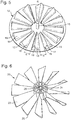
Figure 6 shows a perspective view of the rotary element of the check valve ofFigure 1 . - With reference to
Figures 1 to 4 , acheck valve 2 is illustrated.Check valve 2 is configured to be mounted around its periphery in or to, for example, a duct in order to prevent reverse flow of a fluid through the duct. As shown, thecheck valve 2 comprises a static, generallycircular valve plate 10 and arotary element 20, which is rotatably mounted to thevalve plate 10 about rotational axis R. Although circular in this embodiment, thevalve plate 10 may be of any shape. - As can be seen more clearly in
Figures 5 and 6 ,valve plate 10 comprises ashaft 15 that extends along rotational axis R androtary element 20 comprises abore 25 through thecentral hub 24 that fits overshaft 15 to allowrotary element 20 to be mounted rotatably tovalve plate 10. A bearing (not shown) may be mounted around theshaft 15 and thebore 25 to allow rotation of therotary element 20 around theshaft 15. Alternatively, any other suitable means of providing rotatable mounting of therotary element 20 to thevalve plate 10 as would be understood by one skilled in the art, may be used within the scope of this disclosure. - The
valve plate 10 comprises a plurality ofopenings 13 therethrough. In this case, theopenings 13 are generally triangular or trapezoidal in shape, however, any shape opening may be used within the scope of this disclosure. - The
valve plate 10 also comprisesshrouds 12 that extend upwardly from thevalve plate 10 and around eachopening 13. Theshrouds 12 and thevalve plate 10 definewindows 14. Windows 14 face in at least partially a circumferential direction. As can be seen more clearly inFigures 2 and5 ,shrouds 12 are shaped such that portions of thewindows 14 face in radial and axial (i.e. in the direction of the rotational axis R) directions, in addition to the circumferential direction. However, in alternative embodiments, thewindows 14 may only face the circumferential direction. - A lower portion of each
window 14 adjacent the surface of thevalve plate 10 is defined by alip 16 upstanding from thevalve plate 10. However, in alternative embodiments,valve plate 10 does not comprisesuch lips 16. The function of thelips 16 is described below in relation to the closing of thecheck valve 2. - In the depicted embodiment, the edges of
windows 14 comprise asealing element 19 thereon, which aids closing of the check valve 2 (as described in more detail below).Sealing element 19 may be a resilient and/or compliant material. In alternative embodiments, however, the edges ofwindows 14 do not comprise anadditional sealing element 19. -
Bumper surfaces 18 are formed on or associated with arear surface 17 ofshrouds 12.Bumper surfaces 18 are configured to contact arespective vane 22 along a length thereof, as will be described in more detail below in relation to the opening of thecheck valve 2. As shown inFigures 1 to 5 , therear surface 17 ofshrouds 12 at least partially faces the circumferential direction (i.e. therear surfaces 17 are the back surfaces on the body of theshrouds 12, opposite the windows 14). In the depicted embodiment, thebumper surface 18 comprises a separate bumper element attached to the rear surface of theshroud 12, however, in alternative embodiments,bumper surface 18 is just a specific area of therear surface 17 of theshroud 12 that contacts a length ofvanes 22 in the open position. - The
rotary element 20 has a plurality ofvanes 22 that extend radially from acentral hub 24. Thevanes 22 extend across thevalve plate 10, in betweenadjacent shrouds 12, and have aleading edge 26 that faces thevalve plate 10 surface and is separated by a small gap therefrom. In alternative embodiments, the leadingedge 26 may be in loose contact with thevalve plate 10, as discussed in more detail below. - There are the same number of
vanes 22 as windows 14 (and also shrouds 12 and openings 13). Thevanes 22 are angled relative to the rotational axis R, such that when fluid flow is incident on thevanes 22 in a direction parallel to the rotational axis R therotary element 20 is forced to rotate. - The
check valve 2 has a forward side and a backward side. The backward side is the side of thecheck valve 2 into which shrouds 12 extend, whereas the forward side is the opposite side to the backward side. When in use, thecheck valve 2 can encounter fluid flow in a positive (i.e. forward) flow direction or a negative (i.e. reverse) direction. In the positive flow direction, fluid passes from the forward side to backward side, through theopenings 13 andwindows 14, whereas in the negative flow direction, fluid attempts to pass from the backward side to the forward side through thewindows 14 andopenings 13. - When there is a positive flow differential across the
check valve 2, fluid will flow in the positive flow direction and exit thevalve 2 throughwindows 14. The fluid will be directed ontovanes 22 causing therotary element 20 to rotate into an open position, which permits further fluid flow through thevalve 2. As shown inFigure 3 , when fully open, a length of eachvane 22 will be forced into contact withrespective bumper surface 18. Rotation to this position causes thevanes 22 to exert a force on the bumper surfaces 18. Thebumper surface 18 has a profile which is complementary to that of thevane 22 such that there is contact between them over an area rather than a line contact. - When there is a negative flow differential across the
check valve 2, fluid will flow in the negative flow direction. In this case, fluid flow incident onvanes 22 will causerotary element 20 to rotate eachvane 22 into contact withwindows 14 andlips 16. This prevents fluid from flowing through thewindows 14 to the forward side of thecheck valve 2, placing the valve in a closed position, as shown inFigure 4 . Rotation to this position causes thevanes 22 to exert a force on thewindows 14 and thelips 16. - In order to prevent fluid flow through the
valve 2 in the closed position, thevanes 22 are sized and shaped to completely coverwindows 14. Thewindows 14 andlips 16 are also contoured to complement the shape and profile of thevanes 22.Sealing elements 19 also act to aid sealing between thevanes 22 and thewindows 14. -
Figures 1 to 4 and6 show vanes 22 having an airfoil cross-section, however, it is to be understood thatvanes 22 may also be planar or have any other suitable cross-section, as would be apparent to one skilled in the art. In addition,vanes 22 may also comprise other characteristics such as a twist along their length (i.e. along their radial axis). - As will be understood by one skilled in the art, varying the
vane 22 cross-section and characteristics may be used to tailor the force required to rotate therotary element 20 to provide a certain cracking pressure (i.e. minimum force necessary for thevalve 2 to rotate from a closed to an open position) or to change the valve's response time between opening and closing. It may also be used to tailor the amount of force that thevanes 22 exert on thewindows 14,lips 16, sealingelements 19 and bumper surfaces 18, during opening and closing of the valve. - In embodiments not depicted, but within the scope of this disclosure, a biasing element may be used to bias the
check valve 2 to a closed position. The biasing member may also be used to increase the cracking pressure of thecheck valve 2. The biasing member could be a spring attached between theshrouds 12 and thevanes 22, a spring attached between thehub 24 andshaft 15 or another means that inhibits the rotation of therotary element 20 from the closed position to the open position. - In the depicted embodiment, the leading
edge 26 is positioned above thevalve plate 10 surface. In this way, the leadingedge 26 andvalve plate 10 do not contact each other as thevanes 22 rotate over thevalve plate 10, minimising friction therebetween. However, in alternative embodiments, the leadingedge 26 is in loose contact with thevalve plate 10 surface. This aims to minimise fluid leakage between theleading edge 26 and thevalve plate 10, without generating unacceptable friction or wear. - There are twelve openings 13 (and corresponding numbers of
vanes 22 and shrouds 12) shown, however, it should be understood that only two or more openings (and corresponding numbers ofvanes 22 and shrouds 12) are necessary for thecheck valve 2 to operate. It is believed thatfewer openings 13 may increase the pressure drop across thecheck valve 2. However, as explained below,fewer openings 13 also increases the impact forces exerted by thevanes 22 on thewindows 14,lips 16, sealingelements 19 and bumper surfaces 18. As will be understood by one skilled in the art, this trade-off can be used to tailor the number ofopenings 13 to the given application of thecheck valve 2. In certain embodiments, a suitable number ofopenings 13 is between 10 and 18. - The
openings 13 andwindows 14 are sized to allow sufficient fluid flow therethrough for the application at hand. Theopenings 13 andwindows 14 may therefore be sized to have an area that is any percentage of thetotal valve plate 10 area, as a given application requires. - The size/number of
openings 13, their spacing and subsequent number ofvanes 22 dictates how much angularrotation rotary element 20 may undergo about rotational axis R between the open and closed positions. A lower angular rotation angle α decreases the impact forces exerted by thevanes 22 on thewindows 14,lips 16 and bumper surfaces 18 when thevalve 2 rotates to the closed and open positions. Thus, the number, size and spacing of the openings and the corresponding number ofvanes 22 can be varied to reduce or increase the impact force as desired. In certain embodiments, a suitable angle of angular rotation is in therange 10° ≤ α ≤ 20°, particularly, 14° ≤ α ≤ 18°, and more particularly α = 16°. However, any angular rotation angle between 0° < α < 180° can be used, within the scope of this disclosure. - The reduction of the impact force provided by the combination of the
openings 13 andvanes 22 and any of their characteristics (as described above) may improve the life of thecheck valve 2. - The relatively large size of the
windows 14 spreads the impact force over a larger area relative to other check valves designs, which acts to reduce the stress caused thereby.Lips 16 and sealingelements 19 may also act as areas of reinforcement forwindows 14, which aids the absorption of stress exerted on thewindows 14. Bumper surfaces 18 may also act to reinforce theshrouds 12 and protect them from the force exerted on them by thevanes 22 rotating to the open position. - The various materials and manufacturing process that may be used to produce the
check valve 2 will now be described. - The
valve plate 10 androtary element 20 may be made of a metallic material, a plastic material or a composite material, as a given application or working environment requires. For instance, they may be made of aluminium, titanium, steel or an alloy thereof. They may alternatively be made of an Ni-based alloy. Depending on the application of thecheck valve 2, they may be corrosion resistant or have a corrosion resistant coating applied thereto. In addition or alternatively, they may also have a heat resistant coating applied thereto. - The
valve plate 10 androtary element 20 may be additively manufactured or subtractively manufactured (e.g. machined). Alternatively, they may be cast. Theshrouds 12 andshaft 15 may be integrally formed as part of thevalve plate 10 or may be produced as separate components and coupled thereto. Thevanes 22 may be integrally formed as part of therotary element 20, or may be separate components coupled thereto. -
Lips 16, sealingelements 19 and bumper surfaces 18 may be separate components from thevalve plate 10 and coupled thereto, or alternatively, may be integrally formed as part of thevalve plate 10. Thelips 16, sealingelements 19 andbumpers 18 may be made of the same material as thevalve plate 10, or a different material.Lips 16, sealingelements 19 andbumpers 18 may be made of a more compliant material thanvalve plate 10, such as a rubberised material, to better absorb impact forces or provide improved sealing. Alternatively, thelips 16, sealingelements 19 andbumpers 18 may have undergone a hardening treatment to make them more resilient to impact forces. - Although the figures and the accompanying description describe particular embodiments and examples, it is to be understood that the scope of this disclosure is not to be limited to such specific embodiments, and is, instead, to be determined by the following claims.
Claims (15)
- A check valve (2) comprising:a valve plate (10) comprising a plurality of openings (13) therethrough;a shroud (12) extending from the valve plate (10) around each of the openings (13), the shroud (12) and the valve plate (10) defining an at least partially circumferentially facing window (14); anda rotary element (20) rotatably mounted to the valve plate (10) about a rotational axis (R), the rotary element (20) comprising a plurality of radially extending vanes (22), the rotary element (20) mounted such that each vane (22) is positioned between two adjacent shrouds (12);wherein the vanes (22) are angled such that fluid flow incident thereon in a direction parallel to said rotational axis (R) will rotate the rotary element (20) about the rotational axis (R); and
wherein the rotary element (20) is rotatable between an open position in which the vanes (22) are spaced circumferentially from the windows (14) to allow fluid to flow through the windows (14) via the openings (13), and a closed position in which the vanes (22) close the windows (14), thereby preventing fluid flow therethrough. - The check valve of claim 1, wherein a lower portion of the window (14) is defined by a lip (16) upstanding from the valve plate (10).
- The check valve of claim 2, wherein the lip (16) has a profile complementary to that of the vane (22) to create an area contact therebetween.
- The check valve of any preceding claim, wherein the vanes (22) engage around the respective edges of the windows (14) to close the windows (14).
- The check valve of claim 4, wherein a sealing element (19) is provided around the edges of each window (14).
- The check valve of claim 5, wherein the sealing element (19) is resilient.
- The check valve of any preceding claim, wherein each shroud (12) comprises a bumper surface (18) configured to contact a respective vane (22) along a length thereof in the open position.
- The check valve of claim 7, wherein the bumper surface (18) has a profile complementary to that of the vane (22) to create an area contact therebetween.
- The check valve of claim 7 or 8, wherein the bumper surface (18) comprises a separate bumper element (18).
- The check valve of any preceding claim, wherein the vanes (22) rotate about the rotational axis (R) between the closed and open valve positions through an angle (α) of between 10° and 20°, more narrowly 14° to 18°, for example, 16°.
- The check valve of any preceding claim, wherein the valve plate (10) comprises between 10 and 16 openings (13) and the rotary element (10) comprises the same number of vanes (22).
- The check valve of any preceding claim, wherein the valve plate (10) comprises 12 openings (13) and the rotary element (10) comprises 12 vanes (22).
- The check valve of any preceding claim, wherein the vanes (22) have an airfoil cross-section.
- The check valve of any preceding claim, wherein the vanes (22) feature a twist along their radial axis.
- The check valve of any preceding claim, wherein the rotary element (20) is rotatably mounted onto a shaft (15) extending from the valve plate (10).
Priority Applications (2)
| Application Number | Priority Date | Filing Date | Title |
|---|---|---|---|
| EP16461521.3A EP3244108B1 (en) | 2016-05-10 | 2016-05-10 | Check valves |
| US15/590,404 US10295070B2 (en) | 2016-05-10 | 2017-05-09 | Check valves |
Applications Claiming Priority (1)
| Application Number | Priority Date | Filing Date | Title |
|---|---|---|---|
| EP16461521.3A EP3244108B1 (en) | 2016-05-10 | 2016-05-10 | Check valves |
Publications (2)
| Publication Number | Publication Date |
|---|---|
| EP3244108A1 true EP3244108A1 (en) | 2017-11-15 |
| EP3244108B1 EP3244108B1 (en) | 2019-01-30 |
Family
ID=56068818
Family Applications (1)
| Application Number | Title | Priority Date | Filing Date |
|---|---|---|---|
| EP16461521.3A Active EP3244108B1 (en) | 2016-05-10 | 2016-05-10 | Check valves |
Country Status (2)
| Country | Link |
|---|---|
| US (1) | US10295070B2 (en) |
| EP (1) | EP3244108B1 (en) |
Families Citing this family (6)
| Publication number | Priority date | Publication date | Assignee | Title |
|---|---|---|---|---|
| CN109332025A (en) * | 2018-10-16 | 2019-02-15 | 农业部南京农业机械化研究所 | An axial flow blade anti-drip device and method |
| US10660235B2 (en) * | 2018-10-17 | 2020-05-19 | Arris Enterprises Llc | Fan with pivotable blades, and corresponding electronics cooling system and methods |
| CN109373019B (en) * | 2018-12-17 | 2024-04-26 | 珠海格力电器股份有限公司 | Check valve and compressor |
| CN110296240B (en) * | 2019-05-22 | 2020-11-10 | 苏州贡湖精密制造产业发展有限公司 | Adjustable check valve, automobile engine cooling system and automobile |
| CN110285096A (en) * | 2019-06-17 | 2019-09-27 | 奇鋐科技股份有限公司 | Fan Anti-backflow structure |
| CN112984174B (en) * | 2021-03-01 | 2022-12-27 | 安徽斯瑞尔阀门有限公司 | Check valve driving device and implementation method thereof |
Citations (4)
| Publication number | Priority date | Publication date | Assignee | Title |
|---|---|---|---|---|
| US2496834A (en) * | 1944-01-28 | 1950-02-07 | United Aircraft Corp | Gas valve construction |
| JPH09151838A (en) * | 1995-11-29 | 1997-06-10 | Nissan Motor Co Ltd | Radial piston pump |
| US20120177510A1 (en) * | 2011-01-07 | 2012-07-12 | XCOR Aerospace, Inc. | High-speed check valve suitable for cryogens and high reverse pressure |
| GB2514953A (en) | 2013-01-21 | 2014-12-10 | Hamilton Sundstrand Corp | Check valve with insert |
Family Cites Families (7)
| Publication number | Priority date | Publication date | Assignee | Title |
|---|---|---|---|---|
| US1023885A (en) * | 1901-06-19 | 1912-04-23 | William H Smyth | Valve. |
| US2859771A (en) * | 1954-06-28 | 1958-11-11 | Jersey Prod Res Co | Valve |
| US3094140A (en) | 1960-09-20 | 1963-06-18 | Charles R Miller | Automatic valve for compressors |
| US3118467A (en) | 1961-02-23 | 1964-01-21 | Kuhn John | Automatic check valve |
| US3319560A (en) | 1965-10-11 | 1967-05-16 | Gen Motors Corp | Directional air vent nozzle with flexing vanes |
| US4599081A (en) * | 1982-09-30 | 1986-07-08 | Cohen Fred M | Artificial heart valve |
| US6174232B1 (en) | 1999-09-07 | 2001-01-16 | International Business Machines Corporation | Helically conforming axial fan check valve |
-
2016
- 2016-05-10 EP EP16461521.3A patent/EP3244108B1/en active Active
-
2017
- 2017-05-09 US US15/590,404 patent/US10295070B2/en active Active
Patent Citations (4)
| Publication number | Priority date | Publication date | Assignee | Title |
|---|---|---|---|---|
| US2496834A (en) * | 1944-01-28 | 1950-02-07 | United Aircraft Corp | Gas valve construction |
| JPH09151838A (en) * | 1995-11-29 | 1997-06-10 | Nissan Motor Co Ltd | Radial piston pump |
| US20120177510A1 (en) * | 2011-01-07 | 2012-07-12 | XCOR Aerospace, Inc. | High-speed check valve suitable for cryogens and high reverse pressure |
| GB2514953A (en) | 2013-01-21 | 2014-12-10 | Hamilton Sundstrand Corp | Check valve with insert |
Also Published As
| Publication number | Publication date |
|---|---|
| US20170328484A1 (en) | 2017-11-16 |
| EP3244108B1 (en) | 2019-01-30 |
| US10295070B2 (en) | 2019-05-21 |
Similar Documents
| Publication | Publication Date | Title |
|---|---|---|
| US10295070B2 (en) | Check valves | |
| EP1588082B1 (en) | Butterfly valve | |
| US20150104296A1 (en) | Variable geometry turbocharger | |
| EP3193055B1 (en) | Check valve | |
| EP3220024B1 (en) | Check valve | |
| US10533671B2 (en) | Check valve | |
| EP2604894A1 (en) | Improved leaf seal | |
| DE112015006062T5 (en) | TURBINE | |
| US5570998A (en) | Impeller structure of closed type centrifugal pump | |
| CN215950486U (en) | Butterfly check valve | |
| US10393278B2 (en) | Check valve | |
| JP7664822B2 (en) | Double Eccentric Valve | |
| EP3273122B1 (en) | Check valve | |
| JP2019019975A (en) | Double-eccentric valve | |
| EP4168697B1 (en) | Energy recovery valve system with lateral flow valve for controlling the fluid flow in a duct | |
| US9625054B2 (en) | Shut-off flap | |
| US10619508B2 (en) | Variable turbine geometry vane lever | |
| US20180372233A1 (en) | Check valves | |
| EP3499105B1 (en) | Check valves | |
| EP1975489B1 (en) | Design of a noise suppression wedge for a butterfly outflow valve | |
| EP3098489B1 (en) | Annular valve and power generating apparatus of renewable-energy type | |
| US9897214B2 (en) | Off-set and sine-wave shaped butterfly plate to reduce aero-torque and reduce actuator size | |
| EP3574208B1 (en) | Radial flow runner for a hydraulic machine | |
| US11333034B2 (en) | Nozzle vane | |
| WO2019012850A1 (en) | Double eccentric valve |
Legal Events
| Date | Code | Title | Description |
|---|---|---|---|
| PUAI | Public reference made under article 153(3) epc to a published international application that has entered the european phase |
Free format text: ORIGINAL CODE: 0009012 |
|
| STAA | Information on the status of an ep patent application or granted ep patent |
Free format text: STATUS: THE APPLICATION HAS BEEN PUBLISHED |
|
| AK | Designated contracting states |
Kind code of ref document: A1 Designated state(s): AL AT BE BG CH CY CZ DE DK EE ES FI FR GB GR HR HU IE IS IT LI LT LU LV MC MK MT NL NO PL PT RO RS SE SI SK SM TR |
|
| AX | Request for extension of the european patent |
Extension state: BA ME |
|
| STAA | Information on the status of an ep patent application or granted ep patent |
Free format text: STATUS: REQUEST FOR EXAMINATION WAS MADE |
|
| 17P | Request for examination filed |
Effective date: 20180509 |
|
| RBV | Designated contracting states (corrected) |
Designated state(s): AL AT BE BG CH CY CZ DE DK EE ES FI FR GB GR HR HU IE IS IT LI LT LU LV MC MK MT NL NO PL PT RO RS SE SI SK SM TR |
|
| RIC1 | Information provided on ipc code assigned before grant |
Ipc: F16K 15/02 20060101AFI20180528BHEP Ipc: F16K 15/00 20060101ALI20180528BHEP Ipc: F16K 31/12 20060101ALI20180528BHEP |
|
| GRAP | Despatch of communication of intention to grant a patent |
Free format text: ORIGINAL CODE: EPIDOSNIGR1 |
|
| STAA | Information on the status of an ep patent application or granted ep patent |
Free format text: STATUS: GRANT OF PATENT IS INTENDED |
|
| INTG | Intention to grant announced |
Effective date: 20180803 |
|
| GRAS | Grant fee paid |
Free format text: ORIGINAL CODE: EPIDOSNIGR3 |
|
| GRAA | (expected) grant |
Free format text: ORIGINAL CODE: 0009210 |
|
| STAA | Information on the status of an ep patent application or granted ep patent |
Free format text: STATUS: THE PATENT HAS BEEN GRANTED |
|
| AK | Designated contracting states |
Kind code of ref document: B1 Designated state(s): AL AT BE BG CH CY CZ DE DK EE ES FI FR GB GR HR HU IE IS IT LI LT LU LV MC MK MT NL NO PL PT RO RS SE SI SK SM TR |
|
| REG | Reference to a national code |
Ref country code: GB Ref legal event code: FG4D |
|
| REG | Reference to a national code |
Ref country code: CH Ref legal event code: EP |
|
| REG | Reference to a national code |
Ref country code: AT Ref legal event code: REF Ref document number: 1093540 Country of ref document: AT Kind code of ref document: T Effective date: 20190215 |
|
| REG | Reference to a national code |
Ref country code: IE Ref legal event code: FG4D |
|
| REG | Reference to a national code |
Ref country code: DE Ref legal event code: R096 Ref document number: 602016009650 Country of ref document: DE |
|
| REG | Reference to a national code |
Ref country code: LT Ref legal event code: MG4D |
|
| REG | Reference to a national code |
Ref country code: NL Ref legal event code: MP Effective date: 20190130 |
|
| PG25 | Lapsed in a contracting state [announced via postgrant information from national office to epo] |
Ref country code: FI Free format text: LAPSE BECAUSE OF FAILURE TO SUBMIT A TRANSLATION OF THE DESCRIPTION OR TO PAY THE FEE WITHIN THE PRESCRIBED TIME-LIMIT Effective date: 20190130 Ref country code: PL Free format text: LAPSE BECAUSE OF FAILURE TO SUBMIT A TRANSLATION OF THE DESCRIPTION OR TO PAY THE FEE WITHIN THE PRESCRIBED TIME-LIMIT Effective date: 20190130 Ref country code: SE Free format text: LAPSE BECAUSE OF FAILURE TO SUBMIT A TRANSLATION OF THE DESCRIPTION OR TO PAY THE FEE WITHIN THE PRESCRIBED TIME-LIMIT Effective date: 20190130 Ref country code: PT Free format text: LAPSE BECAUSE OF FAILURE TO SUBMIT A TRANSLATION OF THE DESCRIPTION OR TO PAY THE FEE WITHIN THE PRESCRIBED TIME-LIMIT Effective date: 20190530 Ref country code: NO Free format text: LAPSE BECAUSE OF FAILURE TO SUBMIT A TRANSLATION OF THE DESCRIPTION OR TO PAY THE FEE WITHIN THE PRESCRIBED TIME-LIMIT Effective date: 20190430 Ref country code: ES Free format text: LAPSE BECAUSE OF FAILURE TO SUBMIT A TRANSLATION OF THE DESCRIPTION OR TO PAY THE FEE WITHIN THE PRESCRIBED TIME-LIMIT Effective date: 20190130 Ref country code: LT Free format text: LAPSE BECAUSE OF FAILURE TO SUBMIT A TRANSLATION OF THE DESCRIPTION OR TO PAY THE FEE WITHIN THE PRESCRIBED TIME-LIMIT Effective date: 20190130 Ref country code: NL Free format text: LAPSE BECAUSE OF FAILURE TO SUBMIT A TRANSLATION OF THE DESCRIPTION OR TO PAY THE FEE WITHIN THE PRESCRIBED TIME-LIMIT Effective date: 20190130 |
|
| REG | Reference to a national code |
Ref country code: AT Ref legal event code: MK05 Ref document number: 1093540 Country of ref document: AT Kind code of ref document: T Effective date: 20190130 |
|
| PG25 | Lapsed in a contracting state [announced via postgrant information from national office to epo] |
Ref country code: LV Free format text: LAPSE BECAUSE OF FAILURE TO SUBMIT A TRANSLATION OF THE DESCRIPTION OR TO PAY THE FEE WITHIN THE PRESCRIBED TIME-LIMIT Effective date: 20190130 Ref country code: RS Free format text: LAPSE BECAUSE OF FAILURE TO SUBMIT A TRANSLATION OF THE DESCRIPTION OR TO PAY THE FEE WITHIN THE PRESCRIBED TIME-LIMIT Effective date: 20190130 Ref country code: HR Free format text: LAPSE BECAUSE OF FAILURE TO SUBMIT A TRANSLATION OF THE DESCRIPTION OR TO PAY THE FEE WITHIN THE PRESCRIBED TIME-LIMIT Effective date: 20190130 Ref country code: GR Free format text: LAPSE BECAUSE OF FAILURE TO SUBMIT A TRANSLATION OF THE DESCRIPTION OR TO PAY THE FEE WITHIN THE PRESCRIBED TIME-LIMIT Effective date: 20190501 Ref country code: BG Free format text: LAPSE BECAUSE OF FAILURE TO SUBMIT A TRANSLATION OF THE DESCRIPTION OR TO PAY THE FEE WITHIN THE PRESCRIBED TIME-LIMIT Effective date: 20190430 Ref country code: IS Free format text: LAPSE BECAUSE OF FAILURE TO SUBMIT A TRANSLATION OF THE DESCRIPTION OR TO PAY THE FEE WITHIN THE PRESCRIBED TIME-LIMIT Effective date: 20190530 |
|
| PG25 | Lapsed in a contracting state [announced via postgrant information from national office to epo] |
Ref country code: EE Free format text: LAPSE BECAUSE OF FAILURE TO SUBMIT A TRANSLATION OF THE DESCRIPTION OR TO PAY THE FEE WITHIN THE PRESCRIBED TIME-LIMIT Effective date: 20190130 Ref country code: AL Free format text: LAPSE BECAUSE OF FAILURE TO SUBMIT A TRANSLATION OF THE DESCRIPTION OR TO PAY THE FEE WITHIN THE PRESCRIBED TIME-LIMIT Effective date: 20190130 Ref country code: IT Free format text: LAPSE BECAUSE OF FAILURE TO SUBMIT A TRANSLATION OF THE DESCRIPTION OR TO PAY THE FEE WITHIN THE PRESCRIBED TIME-LIMIT Effective date: 20190130 Ref country code: DK Free format text: LAPSE BECAUSE OF FAILURE TO SUBMIT A TRANSLATION OF THE DESCRIPTION OR TO PAY THE FEE WITHIN THE PRESCRIBED TIME-LIMIT Effective date: 20190130 Ref country code: CZ Free format text: LAPSE BECAUSE OF FAILURE TO SUBMIT A TRANSLATION OF THE DESCRIPTION OR TO PAY THE FEE WITHIN THE PRESCRIBED TIME-LIMIT Effective date: 20190130 Ref country code: RO Free format text: LAPSE BECAUSE OF FAILURE TO SUBMIT A TRANSLATION OF THE DESCRIPTION OR TO PAY THE FEE WITHIN THE PRESCRIBED TIME-LIMIT Effective date: 20190130 Ref country code: SK Free format text: LAPSE BECAUSE OF FAILURE TO SUBMIT A TRANSLATION OF THE DESCRIPTION OR TO PAY THE FEE WITHIN THE PRESCRIBED TIME-LIMIT Effective date: 20190130 |
|
| REG | Reference to a national code |
Ref country code: DE Ref legal event code: R097 Ref document number: 602016009650 Country of ref document: DE |
|
| PG25 | Lapsed in a contracting state [announced via postgrant information from national office to epo] |
Ref country code: SM Free format text: LAPSE BECAUSE OF FAILURE TO SUBMIT A TRANSLATION OF THE DESCRIPTION OR TO PAY THE FEE WITHIN THE PRESCRIBED TIME-LIMIT Effective date: 20190130 |
|
| REG | Reference to a national code |
Ref country code: DE Ref legal event code: R119 Ref document number: 602016009650 Country of ref document: DE |
|
| PLBE | No opposition filed within time limit |
Free format text: ORIGINAL CODE: 0009261 |
|
| STAA | Information on the status of an ep patent application or granted ep patent |
Free format text: STATUS: NO OPPOSITION FILED WITHIN TIME LIMIT |
|
| REG | Reference to a national code |
Ref country code: CH Ref legal event code: PL |
|
| PG25 | Lapsed in a contracting state [announced via postgrant information from national office to epo] |
Ref country code: AT Free format text: LAPSE BECAUSE OF FAILURE TO SUBMIT A TRANSLATION OF THE DESCRIPTION OR TO PAY THE FEE WITHIN THE PRESCRIBED TIME-LIMIT Effective date: 20190130 |
|
| 26N | No opposition filed |
Effective date: 20191031 |
|
| PG25 | Lapsed in a contracting state [announced via postgrant information from national office to epo] |
Ref country code: CH Free format text: LAPSE BECAUSE OF NON-PAYMENT OF DUE FEES Effective date: 20190531 Ref country code: LI Free format text: LAPSE BECAUSE OF NON-PAYMENT OF DUE FEES Effective date: 20190531 Ref country code: MC Free format text: LAPSE BECAUSE OF FAILURE TO SUBMIT A TRANSLATION OF THE DESCRIPTION OR TO PAY THE FEE WITHIN THE PRESCRIBED TIME-LIMIT Effective date: 20190130 |
|
| REG | Reference to a national code |
Ref country code: BE Ref legal event code: MM Effective date: 20190531 |
|
| PG25 | Lapsed in a contracting state [announced via postgrant information from national office to epo] |
Ref country code: SI Free format text: LAPSE BECAUSE OF FAILURE TO SUBMIT A TRANSLATION OF THE DESCRIPTION OR TO PAY THE FEE WITHIN THE PRESCRIBED TIME-LIMIT Effective date: 20190130 Ref country code: LU Free format text: LAPSE BECAUSE OF NON-PAYMENT OF DUE FEES Effective date: 20190510 |
|
| PG25 | Lapsed in a contracting state [announced via postgrant information from national office to epo] |
Ref country code: TR Free format text: LAPSE BECAUSE OF FAILURE TO SUBMIT A TRANSLATION OF THE DESCRIPTION OR TO PAY THE FEE WITHIN THE PRESCRIBED TIME-LIMIT Effective date: 20190130 |
|
| PG25 | Lapsed in a contracting state [announced via postgrant information from national office to epo] |
Ref country code: IE Free format text: LAPSE BECAUSE OF NON-PAYMENT OF DUE FEES Effective date: 20190510 Ref country code: DE Free format text: LAPSE BECAUSE OF NON-PAYMENT OF DUE FEES Effective date: 20191203 |
|
| PG25 | Lapsed in a contracting state [announced via postgrant information from national office to epo] |
Ref country code: BE Free format text: LAPSE BECAUSE OF NON-PAYMENT OF DUE FEES Effective date: 20190531 |
|
| PG25 | Lapsed in a contracting state [announced via postgrant information from national office to epo] |
Ref country code: CY Free format text: LAPSE BECAUSE OF FAILURE TO SUBMIT A TRANSLATION OF THE DESCRIPTION OR TO PAY THE FEE WITHIN THE PRESCRIBED TIME-LIMIT Effective date: 20190130 |
|
| PG25 | Lapsed in a contracting state [announced via postgrant information from national office to epo] |
Ref country code: MT Free format text: LAPSE BECAUSE OF FAILURE TO SUBMIT A TRANSLATION OF THE DESCRIPTION OR TO PAY THE FEE WITHIN THE PRESCRIBED TIME-LIMIT Effective date: 20190130 Ref country code: HU Free format text: LAPSE BECAUSE OF FAILURE TO SUBMIT A TRANSLATION OF THE DESCRIPTION OR TO PAY THE FEE WITHIN THE PRESCRIBED TIME-LIMIT; INVALID AB INITIO Effective date: 20160510 |
|
| PG25 | Lapsed in a contracting state [announced via postgrant information from national office to epo] |
Ref country code: MK Free format text: LAPSE BECAUSE OF FAILURE TO SUBMIT A TRANSLATION OF THE DESCRIPTION OR TO PAY THE FEE WITHIN THE PRESCRIBED TIME-LIMIT Effective date: 20190130 |
|
| P01 | Opt-out of the competence of the unified patent court (upc) registered |
Effective date: 20230522 |
|
| PGFP | Annual fee paid to national office [announced via postgrant information from national office to epo] |
Ref country code: GB Payment date: 20250423 Year of fee payment: 10 |
|
| PGFP | Annual fee paid to national office [announced via postgrant information from national office to epo] |
Ref country code: FR Payment date: 20250423 Year of fee payment: 10 |