EP3244045A1 - Procede de controle d'un dispositif de motorisation et dispositif de motorisation associe - Google Patents
Procede de controle d'un dispositif de motorisation et dispositif de motorisation associe Download PDFInfo
- Publication number
- EP3244045A1 EP3244045A1 EP17170241.8A EP17170241A EP3244045A1 EP 3244045 A1 EP3244045 A1 EP 3244045A1 EP 17170241 A EP17170241 A EP 17170241A EP 3244045 A1 EP3244045 A1 EP 3244045A1
- Authority
- EP
- European Patent Office
- Prior art keywords
- engine
- temperature
- threshold
- valves
- valve
- Prior art date
- Legal status (The legal status is an assumption and is not a legal conclusion. Google has not performed a legal analysis and makes no representation as to the accuracy of the status listed.)
- Granted
Links
Images

Classifications
-
- F—MECHANICAL ENGINEERING; LIGHTING; HEATING; WEAPONS; BLASTING
- F02—COMBUSTION ENGINES; HOT-GAS OR COMBUSTION-PRODUCT ENGINE PLANTS
- F02D—CONTROLLING COMBUSTION ENGINES
- F02D41/00—Electrical control of supply of combustible mixture or its constituents
- F02D41/0002—Controlling intake air
- F02D41/0007—Controlling intake air for control of turbo-charged or super-charged engines
-
- F—MECHANICAL ENGINEERING; LIGHTING; HEATING; WEAPONS; BLASTING
- F02—COMBUSTION ENGINES; HOT-GAS OR COMBUSTION-PRODUCT ENGINE PLANTS
- F02D—CONTROLLING COMBUSTION ENGINES
- F02D13/00—Controlling the engine output power by varying inlet or exhaust valve operating characteristics, e.g. timing
- F02D13/02—Controlling the engine output power by varying inlet or exhaust valve operating characteristics, e.g. timing during engine operation
- F02D13/0203—Variable control of intake and exhaust valves
- F02D13/0215—Variable control of intake and exhaust valves changing the valve timing only
- F02D13/0219—Variable control of intake and exhaust valves changing the valve timing only by shifting the phase, i.e. the opening periods of the valves are constant
-
- F—MECHANICAL ENGINEERING; LIGHTING; HEATING; WEAPONS; BLASTING
- F02—COMBUSTION ENGINES; HOT-GAS OR COMBUSTION-PRODUCT ENGINE PLANTS
- F02D—CONTROLLING COMBUSTION ENGINES
- F02D13/00—Controlling the engine output power by varying inlet or exhaust valve operating characteristics, e.g. timing
- F02D13/02—Controlling the engine output power by varying inlet or exhaust valve operating characteristics, e.g. timing during engine operation
- F02D13/0261—Controlling the valve overlap
-
- F—MECHANICAL ENGINEERING; LIGHTING; HEATING; WEAPONS; BLASTING
- F02—COMBUSTION ENGINES; HOT-GAS OR COMBUSTION-PRODUCT ENGINE PLANTS
- F02D—CONTROLLING COMBUSTION ENGINES
- F02D41/00—Electrical control of supply of combustible mixture or its constituents
- F02D41/0025—Controlling engines characterised by use of non-liquid fuels, pluralities of fuels, or non-fuel substances added to the combustible mixtures
- F02D41/0047—Controlling exhaust gas recirculation [EGR]
- F02D41/005—Controlling exhaust gas recirculation [EGR] according to engine operating conditions
- F02D41/0055—Special engine operating conditions, e.g. for regeneration of exhaust gas treatment apparatus
-
- F—MECHANICAL ENGINEERING; LIGHTING; HEATING; WEAPONS; BLASTING
- F02—COMBUSTION ENGINES; HOT-GAS OR COMBUSTION-PRODUCT ENGINE PLANTS
- F02D—CONTROLLING COMBUSTION ENGINES
- F02D41/00—Electrical control of supply of combustible mixture or its constituents
- F02D41/0025—Controlling engines characterised by use of non-liquid fuels, pluralities of fuels, or non-fuel substances added to the combustible mixtures
- F02D41/0047—Controlling exhaust gas recirculation [EGR]
- F02D41/006—Controlling exhaust gas recirculation [EGR] using internal EGR
-
- F—MECHANICAL ENGINEERING; LIGHTING; HEATING; WEAPONS; BLASTING
- F02—COMBUSTION ENGINES; HOT-GAS OR COMBUSTION-PRODUCT ENGINE PLANTS
- F02D—CONTROLLING COMBUSTION ENGINES
- F02D41/00—Electrical control of supply of combustible mixture or its constituents
- F02D41/02—Circuit arrangements for generating control signals
- F02D41/04—Introducing corrections for particular operating conditions
- F02D41/06—Introducing corrections for particular operating conditions for engine starting or warming up
- F02D41/062—Introducing corrections for particular operating conditions for engine starting or warming up for starting
- F02D41/064—Introducing corrections for particular operating conditions for engine starting or warming up for starting at cold start
-
- F—MECHANICAL ENGINEERING; LIGHTING; HEATING; WEAPONS; BLASTING
- F02—COMBUSTION ENGINES; HOT-GAS OR COMBUSTION-PRODUCT ENGINE PLANTS
- F02D—CONTROLLING COMBUSTION ENGINES
- F02D41/00—Electrical control of supply of combustible mixture or its constituents
- F02D41/22—Safety or indicating devices for abnormal conditions
- F02D41/221—Safety or indicating devices for abnormal conditions relating to the failure of actuators or electrically driven elements
-
- F—MECHANICAL ENGINEERING; LIGHTING; HEATING; WEAPONS; BLASTING
- F02—COMBUSTION ENGINES; HOT-GAS OR COMBUSTION-PRODUCT ENGINE PLANTS
- F02M—SUPPLYING COMBUSTION ENGINES IN GENERAL WITH COMBUSTIBLE MIXTURES OR CONSTITUENTS THEREOF
- F02M26/00—Engine-pertinent apparatus for adding exhaust gases to combustion-air, main fuel or fuel-air mixture, e.g. by exhaust gas recirculation [EGR] systems
- F02M26/02—EGR systems specially adapted for supercharged engines
- F02M26/04—EGR systems specially adapted for supercharged engines with a single turbocharger
- F02M26/05—High pressure loops, i.e. wherein recirculated exhaust gas is taken out from the exhaust system upstream of the turbine and reintroduced into the intake system downstream of the compressor
-
- F—MECHANICAL ENGINEERING; LIGHTING; HEATING; WEAPONS; BLASTING
- F02—COMBUSTION ENGINES; HOT-GAS OR COMBUSTION-PRODUCT ENGINE PLANTS
- F02M—SUPPLYING COMBUSTION ENGINES IN GENERAL WITH COMBUSTIBLE MIXTURES OR CONSTITUENTS THEREOF
- F02M26/00—Engine-pertinent apparatus for adding exhaust gases to combustion-air, main fuel or fuel-air mixture, e.g. by exhaust gas recirculation [EGR] systems
- F02M26/49—Detecting, diagnosing or indicating an abnormal function of the EGR system
-
- F—MECHANICAL ENGINEERING; LIGHTING; HEATING; WEAPONS; BLASTING
- F02—COMBUSTION ENGINES; HOT-GAS OR COMBUSTION-PRODUCT ENGINE PLANTS
- F02M—SUPPLYING COMBUSTION ENGINES IN GENERAL WITH COMBUSTIBLE MIXTURES OR CONSTITUENTS THEREOF
- F02M26/00—Engine-pertinent apparatus for adding exhaust gases to combustion-air, main fuel or fuel-air mixture, e.g. by exhaust gas recirculation [EGR] systems
- F02M26/50—Arrangements or methods for preventing or reducing deposits, corrosion or wear caused by impurities
-
- F—MECHANICAL ENGINEERING; LIGHTING; HEATING; WEAPONS; BLASTING
- F02—COMBUSTION ENGINES; HOT-GAS OR COMBUSTION-PRODUCT ENGINE PLANTS
- F02D—CONTROLLING COMBUSTION ENGINES
- F02D2200/00—Input parameters for engine control
- F02D2200/02—Input parameters for engine control the parameters being related to the engine
- F02D2200/021—Engine temperature
-
- F—MECHANICAL ENGINEERING; LIGHTING; HEATING; WEAPONS; BLASTING
- F02—COMBUSTION ENGINES; HOT-GAS OR COMBUSTION-PRODUCT ENGINE PLANTS
- F02D—CONTROLLING COMBUSTION ENGINES
- F02D2200/00—Input parameters for engine control
- F02D2200/02—Input parameters for engine control the parameters being related to the engine
- F02D2200/04—Engine intake system parameters
- F02D2200/0414—Air temperature
-
- Y—GENERAL TAGGING OF NEW TECHNOLOGICAL DEVELOPMENTS; GENERAL TAGGING OF CROSS-SECTIONAL TECHNOLOGIES SPANNING OVER SEVERAL SECTIONS OF THE IPC; TECHNICAL SUBJECTS COVERED BY FORMER USPC CROSS-REFERENCE ART COLLECTIONS [XRACs] AND DIGESTS
- Y02—TECHNOLOGIES OR APPLICATIONS FOR MITIGATION OR ADAPTATION AGAINST CLIMATE CHANGE
- Y02T—CLIMATE CHANGE MITIGATION TECHNOLOGIES RELATED TO TRANSPORTATION
- Y02T10/00—Road transport of goods or passengers
- Y02T10/10—Internal combustion engine [ICE] based vehicles
- Y02T10/12—Improving ICE efficiencies
-
- Y—GENERAL TAGGING OF NEW TECHNOLOGICAL DEVELOPMENTS; GENERAL TAGGING OF CROSS-SECTIONAL TECHNOLOGIES SPANNING OVER SEVERAL SECTIONS OF THE IPC; TECHNICAL SUBJECTS COVERED BY FORMER USPC CROSS-REFERENCE ART COLLECTIONS [XRACs] AND DIGESTS
- Y02—TECHNOLOGIES OR APPLICATIONS FOR MITIGATION OR ADAPTATION AGAINST CLIMATE CHANGE
- Y02T—CLIMATE CHANGE MITIGATION TECHNOLOGIES RELATED TO TRANSPORTATION
- Y02T10/00—Road transport of goods or passengers
- Y02T10/10—Internal combustion engine [ICE] based vehicles
- Y02T10/40—Engine management systems
Definitions
- the invention relates to a control method of a drive device, more particularly to a device comprising a supercharged internal combustion engine of the diesel type, equipped with an external recirculation circuit of the high-pressure exhaust gases and Variable valve timing (VVT). It also relates to a motorization device for implementing such a method. It finds an advantageous application in the form of a control method embedded in a motor vehicle equipped with a motorization device comprising a diesel engine and further comprising a nitrogen oxide trap or a selective reduction catalyst of the oxides of nitrogen. 'nitrogen.
- Modern supercharged diesel engines of motor vehicles which operate in a lean mixture, are often equipped at the exhaust with at least one post-treatment system of oxides of nitrogen (NOx) emitted in the combustion gases, for example a Nitrogen oxide trap or a selective reduction catalyst of nitrogen oxides, to limit the discharges into the outside atmosphere of these harmful molecules to the environment.
- NOx oxides of nitrogen
- these supercharged diesel engines are also generally equipped with at least one partial exhaust gas recirculation circuit on admission (or: EGR circuit, acronym for: Exhaust Gas Recycling), able to take part of the combustion gases from the engine and to reintroduce them into the engine air intake circuit, by mixing them with the fresh air admitted into the engine. engine.
- EGR circuit acronym for: Exhaust Gas Recycling
- a "high pressure" exhaust gas recirculation circuit comprises a recirculation duct, connected at one end to the circuit engine exhaust, at a point upstream of the turbine of a turbocharger engine, and at its other end to the engine intake circuit at a point downstream of the compressor of the turbocharger. It further comprises a valve, called “EGR valve”, to control the proportion of exhaust gas to be recycled on admission.
- EGR valve a valve, called "EGR valve
- the lacquering of the valve results in a bonding of the shutter of the valve (usually a valve or a flap) on its seat, which prevents the opening of the valve and thus the dosage of recycled gases. This temporarily or permanently prevents the operation of the circuit exhaust gas recirculation, so that the user may be required to change the valve by a professional, and regulatory limits for NOx emissions are not observed .
- the publication FR-A1- 2,902,470 discloses a valve comprising a body, a valve activated by a motor and a valve seat, said valve comprising a valve seat heater.
- the heater increases the temperature of the valve seat to prevent clogging of the valve. It can thus be operated in all operating conditions, especially at low temperatures.
- the known devices and methods which aim to avoid lacquering of the EGR valve are relatively complex to implement. because they require the implementation of additional components in the vehicle, and they lead to an increase in fuel consumption, which is due to the heating process.
- the invention proposes to remedy the defects of the known devices and methods for eliminating the coating of the valves of the EGR circuit HP (partial recirculation circuit at high pressure of the exhaust gases) of a supercharged engine of the diesel type, in the case where the engine is further equipped with a variable VVT type distribution.
- a control method of a motor vehicle drive device comprising: an internal combustion engine of the supercharged diesel type; a partial recirculation circuit at high pressure of the exhaust gas at the inlet provided with a controlled valve; and, variable valve timing means of the engine, said method comprising a nominal setting step of the drive device, for each stabilized operating point of the engine, wherein said valve is open and the valves have a relatively low crossover.
- the temperature representative of the operation of the engine is a coolant temperature.
- the first temperature threshold is substantially between 0 ° C and 5 ° C
- the second threshold is substantially equal to 20 ° C.
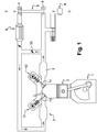
- a motorization device suitable for implementing the method according to the invention. It comprises an internal combustion engine 1 of a motor vehicle, of the supercharged diesel type, equipped with an EGR flue gas recirculation circuit and a variable distribution.
- At least one cylinder 2 of the engine is supplied with air and flue gas from a distributor or intake manifold 3.
- the engine air intake circuit is equipped with a compressor 4 of a turbocharger 5 and a supercharged air cooler 6 mounted downstream of the compressor 4.
- the exhaust system of the engine comprises an exhaust manifold 7, a turbine 8 of the turbocharger 5 and a treatment system 9 of the combustion gases of the engine , comprising for example a nitrogen oxide trap 9 or a selective reduction catalyst of nitrogen oxides 9.
- the exhaust circuit further comprises a bypass which is in the form of a partial recirculation circuit at high pressure (high pressure EGR circuit or HP EGR circuit).
- This EGR circuit takes part of the exhaust gases from the engine at a point upstream of the turbine 8 (in the direction of gas flow) and reintroduces them into the intake circuit of a cylinder 2 downstream.
- compressor 4 in the direction of the airflow into the engine
- This EGR circuit is equipped with a controlled valve 10, called EGR valve 10, whose degree of opening makes it possible to adjust the proportion of recycled gas.
- the motor is equipped with a sensor (not shown) to determine the amount of flue gas reinjected by the EGR circuit. For example, it may be a flowmeter or a pressure sensor.
- the engine 1 is equipped with variable distribution means, constituted here by two actuators 11,12 (shown partially), more precisely variable timing means 11,12 of the intake and exhaust valves 13 of the motor.
- variable distribution means constituted here by two actuators 11,12 (shown partially), more precisely variable timing means 11,12 of the intake and exhaust valves 13 of the motor.
- they can take the form of an electric variator paddle coupled to camshafts for moving the valves.
- the engine is equipped with hydraulic variable valve timing means (or: VVT, for Variable Valve Timing), in which the position of the intake and exhaust valves 13 can be modified. thanks to oil under pressure, when the temperature of the oil is sufficient.
- the amount of burnt gas present in the cylinders 2 at the closing of the intake valve can be obtained in two ways, for a given operating point of the engine speed-load: either by an external recirculation of gas burned, via the EGR circuit, or by an internal recirculation (IGR: Internal Gas Recycling), via the actuators 11,12 of the intake and exhaust valves, which constitute variable distribution means.
- IGR Internal Gas Recycling
- variable distribution makes it possible to carry out an internal recycling of the flue gases in the engine cylinders by controlling the opening and closing of the intake and exhaust valves 14. More specifically, when the intake valves 13 and exhaust 14 are opened simultaneously at the end of the phase of flue gas discharge in the cylinders (when the pistons go back to the top dead center) and at the beginning of the fresh air intake phase ( during the subsequent descent of the pistons), such a so-called "crossed" position of the valves 13, 14 connects the air coming from the intake manifold 3 and the flue gases present in the exhaust manifold 7 of the engine.
- the flue gases present tend to remain in the combustion chambers of the engine: either they are not drained at all, or they are emptied and then sucked back. in the cylinders once the inlet valves 13 of the corresponding cylinders are open, or they are sucked back into the intake manifold 3 and then reintroduced into the combustion chambers once the exhaust valves 14 are closed.
- valves 13,14 The crossing of the valves 13,14 is illustrated at figure 2 .
- the crankshaft angle ⁇ in a cylinder of the engine expressed in degrees from the top dead center (° vil / PMH), and the ordinate valve lift LS, expressed in millimeters.
- Two distinct types of exhaust valve lifts are represented by two dashed line curves, respectively, and two distinct types of intake valve lifts are respectively represented by two solid lines.
- the exhaust and intake valve lifts are represented respectively by the LE and LA curves. These valves are simultaneously open between two crank angles ⁇ 1 and ⁇ 2 around the top dead center TDC.
- variable setting means 11, 12 of the valves 13, 14 make it possible to drive the exhaust valves 14 and the intake valves 13 in one or the other of these extreme positions as well as in the intermediate positions at these extreme positions, as symbolize the arrows on the figure 2 so that the crossover value can be adjusted to obtain a given internal recirculation rate.
- the IGR is preferably piloted during engine transients, that is to say during rapid changes in the point of operation of engine speed-load, in which it is necessary to have a response time. very fast.
- the figure 3 is a logic diagram of the steps of the control method of the motorization device according to one embodiment of the invention.
- the process starts with a step 100 of starting the engine.
- the process then continues with a step 200 in which, conservatively, whatever the point of operation of the engine, and more particularly whatever the speed and its load (or: torque), the EGR valve 10 is closed, and the means variable valve control valves 13,14 are in a relatively high crossing position, for example the maximum crossover value as resulting from the curves LA and LE of the figure 2 .
- the method continues with a step 300 of measuring a temperature value representative of the operation of the engine, preferably the coolant temperature T water .
- This temperature is then compared during a first test step 400 with a first temperature threshold T v1 , called the partial opening threshold of the EGR valve.
- this first temperature threshold may be between 0 ° C and 5 ° C.
- step 200 If said temperature is lower than said first threshold, the process resumes in step 200, the EGR valve 10 remaining closed and the valves maintaining the relatively high crossing of step 200. This ensures that the valve is cold EGR is not maneuvered in the open direction under conditions that could lather, while ensuring a high rate of exhaust gas recirculation thanks to the relatively high crossover of the valves, fully or at least partially compensating the absence of EGR.
- variable distribution means are a hydraulic VVT
- VVT driving being impossible below certain oil temperatures it should be the rest position of the VVT which corresponds to the position of the VVT. more crossed valves.
- the method is directed to a step 500 in which the EGR valve 10 can be partially opened.
- the opening of the valve is limited compared to the opening that is allowed under the normal (hot) engine operating conditions for the stabilized operating point of the engine considered, so as to limit its risks of exposure to lacquering.
- the crossing of the VVT remains identical to that of step 200.
- the method continues with a second test step 600 in which the water temperature T is compared with a second threshold T v2 , called the full opening threshold of the EGR valve, which is greater than the first threshold T v1 .
- said second threshold may be substantially equal to 20 ° C. It corresponds to an operation of the EGR valve 10 without any risk of lacquering, the degree of opening of the valve being not at all limited.
- the value of said second threshold may be adjusted according to test results.
- step 500 the opening of the valve is allowed, but limited.
- step 700 in which the EGR valve can be opened without restriction, and the VVT is controlled so as to adopt a less crossed position than in the step 200 for the same stabilized operating point of the engine.
- the value of the crossing is relatively low, or even zero.
- This control of the VVT even if it is a hydraulic VVT, is possible at this level of coolant temperature because the oil temperature is sufficiently hot too.
- step 700 therefore, the opening of the EGR valve 10 is essentially adjusted according to the level of NO x emissions of the desired vehicle, and the control of the VVT can be used during modes of transient engine operation.
- step 700 the setting adopted corresponds to the normal, i.e. nominal, setting of the operator device, contrary to the settings of steps 200 and 500, which are degraded adjustment modes.
- the second threshold T v2 which corresponds to the full opening threshold of the EGR valve, represents a temperature which eliminates any risk of lacquering taking into account the risks related to the state of the combustion at this temperature, while the first threshold T v1 , which is lower than the second threshold, is chosen to adapt the opening of the valve (by limiting it) to the risk of lacquering higher at this temperature.
- step 500 of the method is replaced by step 200; in other words, the EGR valve remains closed until the temperature has reached the full opening threshold T v2 .
- the method according to the invention provides, for a given operating point of the engine, to limit the NOx emissions of the engine to the source by at least two different settings of the drive device for a stabilized operating point given engine: a first cold adjustment, without EGR but with a high rate of IGR obtained through a relatively high valve cross; and a second hot nominal setting, i.e., above a coolant temperature threshold of the engine, with a high EGR rate and a low rate of IGR obtained through a relatively low valve crossover.
- a first cold adjustment without EGR but with a high rate of IGR obtained through a relatively high valve cross
- a second hot nominal setting i.e., above a coolant temperature threshold of the engine
Landscapes
- Engineering & Computer Science (AREA)
- Chemical & Material Sciences (AREA)
- Combustion & Propulsion (AREA)
- Mechanical Engineering (AREA)
- General Engineering & Computer Science (AREA)
- Exhaust-Gas Circulating Devices (AREA)
- Output Control And Ontrol Of Special Type Engine (AREA)
Abstract
Description
- L'invention concerne un procédé de contrôle d'un dispositif de motorisation, plus particulièrement d'un dispositif comprenant un moteur à combustion interne suralimenté de type diesel, équipé d'un circuit de recirculation externe des gaz d'échappement à haute pression et d'une distribution variable de type VVT (pour Variable Valve Timing, ou distribution à calage variable). Elle concerne également un dispositif de motorisation pour la mise en oeuvre d'un tel procédé. Elle trouve une application avantageuse sous la forme d'un procédé de contrôle embarqué dans un véhicule automobile équipé d'un dispositif de motorisation comprenant un moteur diesel et comprenant en outre un piège à oxydes d'azote ou un catalyseur de réduction sélective des oxydes d'azote.
- Les moteurs diesel suralimentés modernes des véhicules automobiles, qui fonctionnent en mélange pauvre, sont souvent équipés à l'échappement d'au moins un système de post-traitement des oxydes d'azote (NOx) émis dans les gaz de combustion, par exemple un piège à oxydes d'azote ou un catalyseur de réduction sélective des oxydes d'azote, pour limiter les rejets dans l'atmosphère extérieure de ces molécules nuisibles à l'environnement.
- D'autre part, l'efficacité de traitement de ces systèmes de post-traitement étant limitée, ces moteurs diesel suralimentés sont en outre généralement équipés d'au moins un circuit de recirculation partielle des gaz d'échappement à l'admission (ou : circuit EGR, acronyme anglais pour : Exhaust Gas Recycling), apte à prélever une partie des gaz de combustion du moteur et à les réintroduire dans le circuit d'admission d'air du moteur, en les mélangeant à l'air frais admis dans le moteur.
- De manière connue en soi, il en résulte une moindre émission des NOx dans les gaz de combustion du moteur, c'est-à-dire à la source, ce qui permet de diminuer la part de réduction des NOx par le système de post-traitement.
- En particulier, un circuit de recirculation des gaz d'échappement dit « à haute pression » comprend un conduit de recirculation, connecté à une extrémité au circuit d'échappement du moteur, en un point situé en amont de la turbine d'un turbocompresseur du moteur, et à son autre extrémité au circuit d'admission du moteur, en un point situé en aval du compresseur du turbocompresseur. Il comprend en outre une vanne, dite « vanne EGR », afin de contrôler la proportion de gaz d'échappement à recycler à l'admission.
- Or, des conditions de basse température de l'air ambiant et/ou du liquide de refroidissement du moteur, par exemple des conditions inférieures à 0°C, favorisent l'apparition d'un phénomène d'encrassement de la vanne EGR par des hydrocarbures imbrûlés (HC) présents dans les gaz d'échappement. Au contact des parois froides du conduit de recirculation et de la vanne, ces hydrocarbures imbrûlés sont condensés puis polymérisés en composés lourds très adhérents. Dans certaines conditions, par exemple lors d'un démarrage à froid, le circuit de recirculation est traversé par des gaz d'échappement qui ne sont pas suffisamment chauds pour nettoyer les dépôts d'hydrocarbures imbrûlés : ce phénomène est connu sous le nom de « laquage ».
- Le laquage de la vanne se traduit par un collage de l'obturateur de la vanne (généralement une soupape ou un volet) sur son siège, ce qui empêche l'ouverture de la vanne et ainsi le dosage des gaz recyclés. Cela empêche temporairement ou définitivement le fonctionnement du circuit de recirculation des gaz d'échappement, de sorte que l'utilisateur peut être obligé à faire changer la vanne par un professionnel, et que les limites réglementaires d'émissions de NOx ne sont pas respectées.
- Avec la sévérité toujours accrue de la législation, par exemple avec les normes européennes dites Euro6c, Euro6d et Euro7, il devient nécessaire que les véhicules respectent des seuils d'émissions de NOx très faibles dans des conditions ambiantes froides de type hivernal, plus précisément à -7°C. Cet objectif peut être atteint grâce à la présence de gaz brûlés dans les chambres de combustion du moteur, ces gaz pouvant provenir du circuit de recirculation.
- On connaît de l'art antérieur plusieurs dispositifs qui permettent d'activer le recyclage des gaz d'échappement à basse température en ouvrant la vanne EGR : par exemple, la publication
FR-A1- 2 902 470 - L'invention propose de remédier aux défauts des dispositifs et procédés connus d'élimination du laquage des vannes du circuit EGR HP (circuit de recirculation partielle à haute pression des gaz d'échappement) d'un moteur suralimenté de type diesel, dans le cas où le moteur est équipé en outre d'une distribution variable de type VVT.
- Elle propose pour cela un procédé de contrôle d'un dispositif de motorisation de véhicule automobile comprenant : un moteur à combustion interne du type diesel suralimenté ; un circuit de recirculation partielle à haute pression des gaz d'échappement à l'admission pourvu d'une vanne commandée ; et, des moyens de calage variable des soupapes du moteur, ledit procédé comportant une étape de réglage nominal du dispositif de motorisation, pour chaque point de fonctionnement stabilisé du moteur, dans lequel ladite vanne est ouverte et les soupapes présentent un croisement relativement peu élevé.
- Le procédé est caractérisé en ce qu'il comprend en outre :
- Une étape de mesure d'une valeur de température représentative du fonctionnement du moteur ;
- Une étape de comparaison de ladite température avec un premier seuil ; et,
- Lorsque ladite température est inférieure audit premier seuil, une étape de réglage du dispositif de motorisation dans lequel ladite vanne commandée est fermée et les soupapes présentent un croisement relativement élevé, ledit croisement étant plus élevé que celui du réglage nominal pour un même point de fonctionnement stabilisé du moteur.
- Dans un mode de réalisation de l'invention, la température représentative du fonctionnement du moteur est une température de liquide de refroidissement.
- Avantageusement, le procédé selon l'invention comprend en outre :
- Une étape de comparaison de ladite température avec un second seuil supérieur au premier seuil ;
- Lorsque ladite température est comprise entre les premier et second seuils, une étape de réglage du dispositif de motorisation dans lequel ladite vanne est partiellement ouverte et les soupapes présentent un croisement relativement élevé.
- Par exemple, le premier seuil de température est sensiblement compris entre 0°C et 5°C, et le second seuil est sensiblement égal à 20°C.
- D'autres caractéristiques et avantages de l'invention apparaîtront à la lecture d'un mode de réalisation non limitatif de celle-ci, en se reportant aux dessins annexés sur lesquels :
- la
figure 1 représente un exemple de dispositif de motorisation apte à la mise en oeuvre du procédé selon l'invention ; - la
figure 2 est un schéma qui illustre le croisement de soupapes dans un dispositif conforme à lafigure 1 ; et, - la
figure 3 est un logigramme des étapes d'un procédé de contrôle du dispositif de motorisation conforme à l'invention. - Sur la
figure 1 , on a représenté un dispositif de motorisation apte à la mise en oeuvre du procédé selon l'invention. Il comprend un moteur 1 à combustion interne de véhicule automobile, du type diesel suralimenté, équipé d'un circuit de recirculation des gaz brûlés EGR et d'une distribution variable. - Au moins un cylindre 2 du moteur est alimenté en air et en gaz brûlés à partir d'un répartiteur ou collecteur d'admission 3. Le circuit d'admission d'air du moteur est équipé d'un compresseur 4 d'un turbocompresseur 5 et d'un refroidisseur d'air suralimenté 6 monté en aval du compresseur 4. Le circuit d'échappement du moteur comporte un collecteur d'échappement 7, une turbine 8 du turbocompresseur 5 et un système de traitement 9 des gaz de combustion du moteur, comprenant par exemple un piège à oxydes d'azote 9 ou un catalyseur de réduction sélective des oxydes d'azote 9. Le circuit d'échappement comporte en outre une dérivation qui se présente sous la forme d'un circuit de recirculation partielle à haute pression (circuit EGR à haute pression ou circuit EGR HP). Ce circuit EGR prélève une partie des gaz brûlés à l'échappement du moteur en un point situé en amont de la turbine 8 (dans le sens de circulation des gaz) et les réintroduit dans le circuit d'admission d'un cylindre 2 en aval du compresseur 4 (dans le sens de circulation de l'air admis dans le moteur), plus précisément à la sortie du refroidisseur d'air suralimenté 6. Ce circuit EGR est équipé d'une vanne commandée 10, dite vanne EGR 10, dont le degré d'ouverture permet d'ajuster la proportion de gaz recyclés. De plus le moteur est équipé d'un capteur (non représenté) pour déterminer la quantité de gaz brûlés réinjectés par le circuit EGR. Par exemple, il peut s'agir d'un débitmètre ou d'un capteur de pression.
- D'autre part, le moteur 1 est équipé de moyens de distribution variable, constitués ici par deux actionneurs 11,12 (représentés partiellement), plus précisément des moyens de calage variable 11,12 de soupapes d'admission 13 et d'échappement 14 du moteur. Par exemple, ils peuvent prendre la forme d'un variateur électrique à palette couplé à des arbres à cames permettant le déplacement des soupapes. Dans un autre mode de réalisation très courant non représenté ici, le moteur est équipé de moyens de calage variable (ou : VVT, pour Variable Valve Timing) hydrauliques, dans lesquels la position des soupapes d'admission 13 et d'échappement peut être modifiée grâce à de l'huile sous pression, quand la température de l'huile est suffisante.
- Sur ce type de moteur, la quantité de gaz brûlés présente dans les cylindres 2 à la fermeture de la soupape d'admission peut être obtenue de deux façons, pour un point de fonctionnement du moteur régime-charge donné : soit par une recirculation externe de gaz brûlés, via le circuit EGR, soit par une recirculation interne (dite IGR : Internal Gas Recycling), via les actionneurs 11,12 des soupapes d'admission et d'échappement, qui constituent des moyens de distribution variable.
- La distribution variable, ou VVT, permet de réaliser un recyclage interne des gaz brûlés dans les cylindres du moteur en commandant l'ouverture et la fermeture des soupapes d'admission 13 et d'échappement 14. Plus précisément, lorsque les soupapes d'admission 13 et d'échappement 14 sont ouvertes simultanément à la fin de la phase de vidange des gaz brûlés dans les cylindres (lors de la remontée des pistons vers le point mort haut) et au début de la phase d'aspiration d'air frais (lors de la descente des pistons qui s'ensuit), une telle position dite « croisée » des soupapes 13,14 met en relation l'air provenant du collecteur d'admission 3 et les gaz brûlés présents dans le collecteur d'échappement 7 du moteur. Lorsque la pression instantanée à l'échappement est supérieure à la pression instantanée à l'admission, les gaz brûlés présents ont tendance à rester dans les chambres de combustion du moteur : soit ils ne sont pas vidangés du tout, soit ils sont vidangés puis réaspirés dans les cylindres une fois que les soupapes d'admission 13 des cylindres correspondants sont ouvertes, soit ils sont réaspirés dans le collecteur d'admission 3 puis réintroduits dans les chambres de combustion une fois que les soupapes d'échappement 14 sont fermées.
- Le croisement des soupapes 13,14 est illustré à la
figure 2 . Sur cette figure, on a représenté en abscisse l'angle de vilebrequin α dans un cylindre du moteur, exprimé en degrés par rapport au point mort haut (°vil/PMH), et en ordonnée la levée de soupape LS, exprimée en millimètres. Deux types distincts de levées de la soupape d'échappement sont représentés respectivement par deux courbes en traits pointillés, et deux types distincts de levées de la soupape d'admission sont représentés respectivement par deux courbes en traits pleins. - Dans leurs positions respectives les plus croisées, les levées de soupape d'échappement et d'admission sont représentées respectivement par les courbes LE et LA. Ces soupapes sont simultanément ouvertes entre deux angles de vilebrequin α1 et α2 autour du point mort haut PMH.
- Les positions les plus décroisées de la soupape d'échappement et d'admission sont représentées respectivement par les deux autres courbes de la figure respectivement en traits pointillés et en traits pleins. On voit sur la figure que les soupapes ne sont pas, ou ne sont que peu, ouvertes simultanément au voisinage du PMH, contrairement au cas précédent.
- Les moyens de calage variable 11,12 des soupapes 13,14 permettent de piloter les soupapes d'échappement 14 et d'admission 13 dans l'une ou l'autre de ces positions extrêmes ainsi que dans les positions intermédiaires à ces positions extrêmes, comme le symbolisent les flèches sur la
figure 2 , de sorte qu'on peut ajuster la valeur de croisement pour obtenir un taux de recirculation interne donné. - Les avantages du recyclage interne par rapport au recyclage externe sont la réaction rapide du système et une bonne répartition des gaz recyclés. En effet, les deux sources de gaz recyclés possèdent des temps de réponse distincts. Pour piloter l'IGR, on joue sur le déphasage des soupapes qui est très rapide. En revanche, piloter l'EGR est plus lent car le temps d'écoulement des gaz brûlés dans le circuit des gaz d'échappement est long, du fait de la longueur de ce circuit.
- C'est pourquoi on pilote de préférence l'IGR lors de transitoires du moteur, c'est-à-dire lors de modifications rapides du point de fonctionnement régime-charge du moteur, dans lesquelles il est nécessaire d'avoir un temps de réponse très rapide.
- La
figure 3 est un logigramme des étapes du procédé de contrôle du dispositif de motorisation selon un mode de réalisation de l'invention. - Le procédé débute par une étape 100 de démarrage du moteur. Le procédé se poursuit alors par une étape 200 dans laquelle, de manière conservatoire, quel que soit le point de fonctionnement du moteur, et plus particulièrement quels que soit le régime et sa charge (ou : couple), la vanne EGR 10 est fermée, et les moyens de distribution variable pilotent les soupapes 13,14 sont dans une position de croisement relativement élevé, par exemple la valeur de croisement maximale telle que résultant des courbes LA et LE de la
figure 2 . - Le procédé se poursuit par une étape 300 de mesure d'une valeur de température représentative du fonctionnement du moteur, de préférence la température de liquide de refroidissement Teau. Cette température est ensuite comparée lors d'une première étape de test 400 avec un premier seuil de température Tv1, dit seuil d'ouverture partielle de vanne EGR. Par exemple, ce premier seuil de température peut être compris entre 0°C et 5°C.
- Si ladite température est inférieure audit premier seuil, le procédé reprend à l'étape 200, la vanne EGR 10 restant fermée et les soupapes conservant le croisement relativement élevé de l'étape 200. On s'assure ainsi qu'à froid, la vanne EGR n'est pas manoeuvrée dans le sens de l'ouverture dans des conditions qui risqueraient de la laquer, tout en assurant un taux de recyclage des gaz d'échappement important grâce au croisement relativement élevé des soupapes, compensant totalement ou au moins en partie l'absence d'EGR.
- On notera que, dans le cas où les moyens de distribution variable sont un VVT hydraulique, un pilotage du VVT étant impossible en dessous de certaines températures d'huile, il convient que ce soit la position de repos du VVT qui corresponde à la position la plus croisée des soupapes.
- Dans le cas contraire où ladite température est supérieure audit premier seuil, le procédé oriente vers une étape 500 dans laquelle la vanne EGR 10 peut être ouverte partiellement. Plus précisément, l'ouverture de la vanne est limitée par rapport à l'ouverture qui est autorisée dans les conditions de fonctionnement normales (à chaud) du moteur pour le point de fonctionnement stabilisé considéré du moteur, de manière à limiter ses risques d'exposition au laquage. Le croisement du VVT reste identique à celui de l'étape 200.
- Le procédé se poursuit par une deuxième étape de test 600 dans laquelle la température Teau est comparée à un deuxième seuil Tv2, dit seuil d'ouverture complète de la vanne EGR, qui est supérieur au premier seuil Tv1. Par exemple, ledit deuxième seuil peut être sensiblement égal à 20°C. Il correspond à un fonctionnement de la vanne EGR 10 sans aucun risque de laquage, le degré d'ouverture de la vanne n'étant pas du tout limité. Bien entendu, la valeur dudit deuxième seuil peut être ajustée en fonction de résultats d'essais.
- Si ladite température est inférieure audit deuxième seuil, le procédé reprend à l'étape 500 dans laquelle l'ouverture de la vanne est autorisée, mais limitée. Dans le cas contraire, il oriente vers une étape 700 dans laquelle la vanne EGR peut être ouverte sans restriction, et le VVT est piloté de manière à adopter une position moins croisée qu'à l'étape 200 pour le même point de fonctionnement stabilisé du moteur. En référence à la
figure 2 , la valeur du croisement est relativement peu élevée, voire nulle. Ce pilotage du VVT, même si il s'agit d'un VVT hydraulique, est possible à ce niveau de température de liquide de refroidissement car la température d'huile est suffisamment chaude également. A l'étape 700, on règle donc essentiellement l'ouverture de la vanne EGR 10 en fonction du niveau d'émissions de NOx du véhicule souhaité, et on peut utiliser le pilotage du VVT lors de modes de fonctionnement transitoire du moteur, c'est-à-dire lors de variations rapides du point de fonctionnement du moteur, afin de mettre à profit le temps de réponse rapide d'un tel pilotage. A l'étape 700, le réglage adopté correspond au réglage normal, c'est-à-dire nominal, du dispositif de motorisation, contrairement aux réglages des étapes 200 et 500, qui sont des modes de réglages dégradés. - On notera que le deuxième seuil Tv2, qui correspond au seuil d'ouverture complète de la vanne EGR, représente une température qui élimine tout risque de laquage compte tenu des risques liés à l'état de la combustion à cette température, tandis que le premier seuil Tv1, qui est inférieur au deuxième seuil, est choisi pour adapter l'ouverture de la vanne (en la limitant) au risque de laquage plus élevé à cette température.
- En variante du procédé qui a été décrit à la
figure 3 , il est entendu qu'on peut ne pas souhaiter étendre la plage d'utilisation de l'EGR en dessous du deuxième seuil Tv2. Dans ce cas, l'étape 500 du procédé est remplacée par l'étape 200 ; en d'autres termes, la vanne EGR reste fermée tant que la température n'a pas atteint le seuil d'ouverture complète Tv2. - En résumé, le procédé selon l'invention propose, pour un point de fonctionnement donné du moteur, de limiter les émissions de NOx du moteur à la source par au moins deux réglages distincts du dispositif de motorisation, pour un point de fonctionnement stabilisé du moteur donné : un premier réglage à froid, sans EGR mais avec un taux d'IGR important obtenu grâce à un croisement de soupapes relativement élevé ; et, un deuxième réglage nominal à chaud, c'est-à-dire au-dessus d'un seuil de température de liquide de refroidissement du moteur, avec un taux d'EGR important et un faible taux d'IGR obtenu grâce à un croisement de soupapes relativement peu élevé. De cette manière, on évite d'actionner la vanne EGR à des températures très basses où elle pourrait subir un laquage, tout en compensant totalement ou partiellement, grâce à l'IGR, l'augmentation des émissions de NOx due à l'absence d'EGR à froid.
- Pour un point de fonctionnement stabilisé donné du moteur, on peut prévoir en outre un troisième réglage pour des températures intermédiaires entre le fonctionnement à froid et le fonctionnement à chaud, dans lequel le taux d'EGR est inférieur au taux d'EGR du réglage nominal (à chaud), le taux d'IGR élevé étant identique au taux du réglage à froid.
Claims (4)
- Procédé de contrôle d'un dispositif de motorisation de véhicule automobile comprenant un moteur (2) à combustion interne du type diesel suralimenté ; un circuit de recirculation partielle à haute pression des gaz d'échappement à l'admission pourvu d'une vanne commandée (10) ; et, des moyens de calage variable (11,12) des soupapes (13,14) du moteur (2), ledit procédé comportant une étape (700) de réglage nominal du dispositif de motorisation, pour chaque point de fonctionnement stabilisé du moteur (2), dans lequel ladite vanne commandée (10) est ouverte et les soupapes (13,14) présentent un croisement relativement peu élevé,
CARACTERISE EN CE QU'il comprend en outre :- une étape (300) de mesure d'une valeur de température (Teau) représentative du fonctionnement du moteur (1) ;- une étape (400) de comparaison de ladite température avec un premier seuil (Tv1) ; et,- lorsque ladite température (Teau) est inférieure audit premier seuil (Tv1), une étape (200) de réglage du dispositif de motorisation dans lequel ladite vanne commandée (10) est fermée et les soupapes (13,14) présentent un croisement relativement élevé, ledit croisement étant plus élevé que celui du réglage nominal pour un même point de fonctionnement stabilisé du moteur. - Procédé selon la revendication 1, dans lequel la température représentative du fonctionnement du moteur (Teau) est une température du liquide de refroidissement du moteur.
- Procédé selon l'une quelconque des revendications précédentes, caractérisé en ce qu'il comprend en outre :- Une étape (600) de comparaison de ladite température (Teau) avec un second seuil (Tv2) supérieur au premier seuil (Tv1) ; et,- Lorsque ladite température (Teau) est comprise entre les premier et second seuils (Tv1, Tv2) de température, une étape (500) de réglage du dispositif de motorisation dans lequel ladite vanne commandée (10) est partiellement ouverte et les soupapes (13,14) présentent un croisement relativement élevé identique au réglage de l'étape (200) pour un même point de fonctionnement stabilisé du moteur.
- Procédé selon l'une quelconque des revendications précédentes, dans lequel le premier seuil (Tv1) de température est sensiblement compris entre 0°C et 5°C, et dans lequel le second seuil (Tv2) est sensiblement égal à 20°C.
Applications Claiming Priority (1)
| Application Number | Priority Date | Filing Date | Title |
|---|---|---|---|
| FR1654143A FR3051224B1 (fr) | 2016-05-10 | 2016-05-10 | Procede de controle d'un dispositif de motorisation et dispositif de motorisation associe |
Publications (2)
| Publication Number | Publication Date |
|---|---|
| EP3244045A1 true EP3244045A1 (fr) | 2017-11-15 |
| EP3244045B1 EP3244045B1 (fr) | 2019-07-24 |
Family
ID=56148563
Family Applications (1)
| Application Number | Title | Priority Date | Filing Date |
|---|---|---|---|
| EP17170241.8A Active EP3244045B1 (fr) | 2016-05-10 | 2017-05-09 | Procede de controle d'un dispositif de motorisation et dispositif de motorisation associe |
Country Status (2)
| Country | Link |
|---|---|
| EP (1) | EP3244045B1 (fr) |
| FR (1) | FR3051224B1 (fr) |
Citations (8)
| Publication number | Priority date | Publication date | Assignee | Title |
|---|---|---|---|---|
| US6273056B1 (en) * | 1997-12-15 | 2001-08-14 | Nissan Motor Co., Ltd. | Control system for diesel engine during cold-engine warm-up |
| US20050193995A1 (en) * | 2004-03-02 | 2005-09-08 | Mitsuhiro Nomura | Exhaust gas recirculation controller |
| FR2902470A1 (fr) | 2006-06-19 | 2007-12-21 | Peugeot Citroen Automobiles Sa | Systeme de rechauffage du siege de soupape d'une vanne egr |
| US20080190107A1 (en) * | 2005-10-05 | 2008-08-14 | Toyota Jidosha Kabushiki Kaisha | Startup Control Apparatus of Internal Combustion Engine and Control Method Thereof |
| US20090078223A1 (en) * | 2007-09-20 | 2009-03-26 | Hitachi, Ltd. | Variable valve system of internal combustion engine |
| FR2944323A3 (fr) * | 2009-04-14 | 2010-10-15 | Renault Sas | Procede d'estimation du taux de gaz brules residuels pour un moteur, en particulier du type diesel suralimente, et moteur correspondant |
| DE102011113925A1 (de) * | 2011-09-21 | 2013-03-21 | GM Global Technology Operations LLC (n. d. Gesetzen des Staates Delaware) | Verfahren zum Steuern und/oder Regeln eines Verbrennungsmotors |
| FR3019230A1 (fr) * | 2014-04-01 | 2015-10-02 | Renault Sas | Moteur a combustion equipe d'un prechauffage des gaz d'echappement recycles |
-
2016
- 2016-05-10 FR FR1654143A patent/FR3051224B1/fr not_active Expired - Fee Related
-
2017
- 2017-05-09 EP EP17170241.8A patent/EP3244045B1/fr active Active
Patent Citations (8)
| Publication number | Priority date | Publication date | Assignee | Title |
|---|---|---|---|---|
| US6273056B1 (en) * | 1997-12-15 | 2001-08-14 | Nissan Motor Co., Ltd. | Control system for diesel engine during cold-engine warm-up |
| US20050193995A1 (en) * | 2004-03-02 | 2005-09-08 | Mitsuhiro Nomura | Exhaust gas recirculation controller |
| US20080190107A1 (en) * | 2005-10-05 | 2008-08-14 | Toyota Jidosha Kabushiki Kaisha | Startup Control Apparatus of Internal Combustion Engine and Control Method Thereof |
| FR2902470A1 (fr) | 2006-06-19 | 2007-12-21 | Peugeot Citroen Automobiles Sa | Systeme de rechauffage du siege de soupape d'une vanne egr |
| US20090078223A1 (en) * | 2007-09-20 | 2009-03-26 | Hitachi, Ltd. | Variable valve system of internal combustion engine |
| FR2944323A3 (fr) * | 2009-04-14 | 2010-10-15 | Renault Sas | Procede d'estimation du taux de gaz brules residuels pour un moteur, en particulier du type diesel suralimente, et moteur correspondant |
| DE102011113925A1 (de) * | 2011-09-21 | 2013-03-21 | GM Global Technology Operations LLC (n. d. Gesetzen des Staates Delaware) | Verfahren zum Steuern und/oder Regeln eines Verbrennungsmotors |
| FR3019230A1 (fr) * | 2014-04-01 | 2015-10-02 | Renault Sas | Moteur a combustion equipe d'un prechauffage des gaz d'echappement recycles |
Also Published As
| Publication number | Publication date |
|---|---|
| FR3051224B1 (fr) | 2019-11-15 |
| FR3051224A1 (fr) | 2017-11-17 |
| EP3244045B1 (fr) | 2019-07-24 |
Similar Documents
| Publication | Publication Date | Title |
|---|---|---|
| EP3574194B1 (fr) | Procede de controle des emissions d'oxydes d'azote a l'echappement d'un moteur a combustion interne | |
| EP1774144B1 (fr) | Systeme d'aide a la regeneration de moyens de depollution | |
| EP1632668B1 (fr) | Procédé de contrôle d'un moteur à combustion interne à injection directe de carburant et moteur utilisant un tel procédé | |
| FR3058464A1 (fr) | Systeme d'injection d'air dans un circuit d'echappement de gaz d'un moteur thermique suralimente. | |
| EP3244045B1 (fr) | Procede de controle d'un dispositif de motorisation et dispositif de motorisation associe | |
| EP2620631A1 (fr) | Groupe moteur à deux collecteurs d'échappement | |
| FR3044359A1 (fr) | Procede de commande d'un moteur a combustion interne. | |
| FR3058472B1 (fr) | Procede de commande d'un moteur thermique suralimente equipe d'un mecanisme de deconnexion de cylindres. | |
| WO2011004091A1 (fr) | Procede de controle d'un debit d'air injecte dans un moteur, ensemble comprenant un calculateur mettant en oeuvre le procede et un vehicule comprenant l'ensemble | |
| WO2022184480A1 (fr) | Procédé et système de commande d'un moteur à combustion interne à allumage commandé en phase de levé de pied. | |
| WO2016156715A1 (fr) | Dispositif comportant un circuit de recirculation de gaz d'echappement | |
| FR3089562A1 (fr) | Procédé de commande d’un moteur à combustion interne suralimenté | |
| FR2935026A1 (fr) | Systeme de re-circulation de gaz d'echappement et procede de controle correspondant | |
| EP2250360A1 (fr) | Systeme de controle d'un moteur thermique a recirculation des gaz d'echappement | |
| EP3330521B1 (fr) | Procédé de purge d'un piège à oxydes d'azote d'un moteur à combustion interne | |
| FR3058471A1 (fr) | Procede de commande d'un moteur thermique suralimente comprenant une ligne de recirculation des gaz d'echappement. | |
| FR2836514A1 (fr) | Procede et dispositif de commande du fonctionnement d'un moteur a combustion interne | |
| FR2903735A1 (fr) | Systeme de commande d'un moteur a combustion du type diesel suralimente avec recirculation des gaz d'echappement | |
| FR2904051A1 (fr) | Procede de regeneration d'un filtre a particules | |
| FR3151633A1 (fr) | Système et procédé de commande d’un moteur à combustion interne en phase de lever de pied | |
| EP2562400A1 (fr) | Procédé de régénération d'un filtre à particules de moteur à combustion interne | |
| FR2877054A1 (fr) | Moteur a combustion interne diesel ou essence a injection directe a taux de gaz brules augmente | |
| FR3069282A1 (fr) | Procede de commande d'un moteur a combustion interne suralimente | |
| WO2024105256A1 (fr) | Procédé de commande d'un moteur de véhicule automobile comprenant au moins un mode de réglage du moteur visant à augmenter la quantité de calories issues du moteur utilisée par un système de chauffage du véhicule | |
| FR3144846A1 (fr) | Procédé d'optimisation de la performance stabilisée en conditions extrêmes d'un moteur à combustion interne suralimenté |
Legal Events
| Date | Code | Title | Description |
|---|---|---|---|
| PUAI | Public reference made under article 153(3) epc to a published international application that has entered the european phase |
Free format text: ORIGINAL CODE: 0009012 |
|
| STAA | Information on the status of an ep patent application or granted ep patent |
Free format text: STATUS: THE APPLICATION HAS BEEN PUBLISHED |
|
| AK | Designated contracting states |
Kind code of ref document: A1 Designated state(s): AL AT BE BG CH CY CZ DE DK EE ES FI FR GB GR HR HU IE IS IT LI LT LU LV MC MK MT NL NO PL PT RO RS SE SI SK SM TR |
|
| AX | Request for extension of the european patent |
Extension state: BA ME |
|
| STAA | Information on the status of an ep patent application or granted ep patent |
Free format text: STATUS: REQUEST FOR EXAMINATION WAS MADE |
|
| 17P | Request for examination filed |
Effective date: 20180517 |
|
| RBV | Designated contracting states (corrected) |
Designated state(s): AL AT BE BG CH CY CZ DE DK EE ES FI FR GB GR HR HU IE IS IT LI LT LU LV MC MK MT NL NO PL PT RO RS SE SI SK SM TR |
|
| GRAP | Despatch of communication of intention to grant a patent |
Free format text: ORIGINAL CODE: EPIDOSNIGR1 |
|
| STAA | Information on the status of an ep patent application or granted ep patent |
Free format text: STATUS: GRANT OF PATENT IS INTENDED |
|
| INTG | Intention to grant announced |
Effective date: 20190206 |
|
| GRAS | Grant fee paid |
Free format text: ORIGINAL CODE: EPIDOSNIGR3 |
|
| GRAA | (expected) grant |
Free format text: ORIGINAL CODE: 0009210 |
|
| STAA | Information on the status of an ep patent application or granted ep patent |
Free format text: STATUS: THE PATENT HAS BEEN GRANTED |
|
| AK | Designated contracting states |
Kind code of ref document: B1 Designated state(s): AL AT BE BG CH CY CZ DE DK EE ES FI FR GB GR HR HU IE IS IT LI LT LU LV MC MK MT NL NO PL PT RO RS SE SI SK SM TR |
|
| REG | Reference to a national code |
Ref country code: GB Ref legal event code: FG4D Free format text: NOT ENGLISH |
|
| REG | Reference to a national code |
Ref country code: CH Ref legal event code: EP |
|
| REG | Reference to a national code |
Ref country code: DE Ref legal event code: R096 Ref document number: 602017005435 Country of ref document: DE |
|
| REG | Reference to a national code |
Ref country code: AT Ref legal event code: REF Ref document number: 1158481 Country of ref document: AT Kind code of ref document: T Effective date: 20190815 |
|
| REG | Reference to a national code |
Ref country code: IE Ref legal event code: FG4D Free format text: LANGUAGE OF EP DOCUMENT: FRENCH |
|
| REG | Reference to a national code |
Ref country code: NL Ref legal event code: MP Effective date: 20190724 |
|
| REG | Reference to a national code |
Ref country code: LT Ref legal event code: MG4D |
|
| REG | Reference to a national code |
Ref country code: AT Ref legal event code: MK05 Ref document number: 1158481 Country of ref document: AT Kind code of ref document: T Effective date: 20190724 |
|
| PG25 | Lapsed in a contracting state [announced via postgrant information from national office to epo] |
Ref country code: SE Free format text: LAPSE BECAUSE OF FAILURE TO SUBMIT A TRANSLATION OF THE DESCRIPTION OR TO PAY THE FEE WITHIN THE PRESCRIBED TIME-LIMIT Effective date: 20190724 Ref country code: AT Free format text: LAPSE BECAUSE OF FAILURE TO SUBMIT A TRANSLATION OF THE DESCRIPTION OR TO PAY THE FEE WITHIN THE PRESCRIBED TIME-LIMIT Effective date: 20190724 Ref country code: PT Free format text: LAPSE BECAUSE OF FAILURE TO SUBMIT A TRANSLATION OF THE DESCRIPTION OR TO PAY THE FEE WITHIN THE PRESCRIBED TIME-LIMIT Effective date: 20191125 Ref country code: NL Free format text: LAPSE BECAUSE OF FAILURE TO SUBMIT A TRANSLATION OF THE DESCRIPTION OR TO PAY THE FEE WITHIN THE PRESCRIBED TIME-LIMIT Effective date: 20190724 Ref country code: BG Free format text: LAPSE BECAUSE OF FAILURE TO SUBMIT A TRANSLATION OF THE DESCRIPTION OR TO PAY THE FEE WITHIN THE PRESCRIBED TIME-LIMIT Effective date: 20191024 Ref country code: NO Free format text: LAPSE BECAUSE OF FAILURE TO SUBMIT A TRANSLATION OF THE DESCRIPTION OR TO PAY THE FEE WITHIN THE PRESCRIBED TIME-LIMIT Effective date: 20191024 Ref country code: FI Free format text: LAPSE BECAUSE OF FAILURE TO SUBMIT A TRANSLATION OF THE DESCRIPTION OR TO PAY THE FEE WITHIN THE PRESCRIBED TIME-LIMIT Effective date: 20190724 Ref country code: LT Free format text: LAPSE BECAUSE OF FAILURE TO SUBMIT A TRANSLATION OF THE DESCRIPTION OR TO PAY THE FEE WITHIN THE PRESCRIBED TIME-LIMIT Effective date: 20190724 Ref country code: HR Free format text: LAPSE BECAUSE OF FAILURE TO SUBMIT A TRANSLATION OF THE DESCRIPTION OR TO PAY THE FEE WITHIN THE PRESCRIBED TIME-LIMIT Effective date: 20190724 |
|
| PG25 | Lapsed in a contracting state [announced via postgrant information from national office to epo] |
Ref country code: GR Free format text: LAPSE BECAUSE OF FAILURE TO SUBMIT A TRANSLATION OF THE DESCRIPTION OR TO PAY THE FEE WITHIN THE PRESCRIBED TIME-LIMIT Effective date: 20191025 Ref country code: LV Free format text: LAPSE BECAUSE OF FAILURE TO SUBMIT A TRANSLATION OF THE DESCRIPTION OR TO PAY THE FEE WITHIN THE PRESCRIBED TIME-LIMIT Effective date: 20190724 Ref country code: IS Free format text: LAPSE BECAUSE OF FAILURE TO SUBMIT A TRANSLATION OF THE DESCRIPTION OR TO PAY THE FEE WITHIN THE PRESCRIBED TIME-LIMIT Effective date: 20191124 Ref country code: AL Free format text: LAPSE BECAUSE OF FAILURE TO SUBMIT A TRANSLATION OF THE DESCRIPTION OR TO PAY THE FEE WITHIN THE PRESCRIBED TIME-LIMIT Effective date: 20190724 Ref country code: RS Free format text: LAPSE BECAUSE OF FAILURE TO SUBMIT A TRANSLATION OF THE DESCRIPTION OR TO PAY THE FEE WITHIN THE PRESCRIBED TIME-LIMIT Effective date: 20190724 Ref country code: ES Free format text: LAPSE BECAUSE OF FAILURE TO SUBMIT A TRANSLATION OF THE DESCRIPTION OR TO PAY THE FEE WITHIN THE PRESCRIBED TIME-LIMIT Effective date: 20190724 |
|
| PG25 | Lapsed in a contracting state [announced via postgrant information from national office to epo] |
Ref country code: TR Free format text: LAPSE BECAUSE OF FAILURE TO SUBMIT A TRANSLATION OF THE DESCRIPTION OR TO PAY THE FEE WITHIN THE PRESCRIBED TIME-LIMIT Effective date: 20190724 |
|
| PG25 | Lapsed in a contracting state [announced via postgrant information from national office to epo] |
Ref country code: DK Free format text: LAPSE BECAUSE OF FAILURE TO SUBMIT A TRANSLATION OF THE DESCRIPTION OR TO PAY THE FEE WITHIN THE PRESCRIBED TIME-LIMIT Effective date: 20190724 Ref country code: PL Free format text: LAPSE BECAUSE OF FAILURE TO SUBMIT A TRANSLATION OF THE DESCRIPTION OR TO PAY THE FEE WITHIN THE PRESCRIBED TIME-LIMIT Effective date: 20190724 Ref country code: IT Free format text: LAPSE BECAUSE OF FAILURE TO SUBMIT A TRANSLATION OF THE DESCRIPTION OR TO PAY THE FEE WITHIN THE PRESCRIBED TIME-LIMIT Effective date: 20190724 Ref country code: EE Free format text: LAPSE BECAUSE OF FAILURE TO SUBMIT A TRANSLATION OF THE DESCRIPTION OR TO PAY THE FEE WITHIN THE PRESCRIBED TIME-LIMIT Effective date: 20190724 Ref country code: RO Free format text: LAPSE BECAUSE OF FAILURE TO SUBMIT A TRANSLATION OF THE DESCRIPTION OR TO PAY THE FEE WITHIN THE PRESCRIBED TIME-LIMIT Effective date: 20190724 |
|
| PG25 | Lapsed in a contracting state [announced via postgrant information from national office to epo] |
Ref country code: CZ Free format text: LAPSE BECAUSE OF FAILURE TO SUBMIT A TRANSLATION OF THE DESCRIPTION OR TO PAY THE FEE WITHIN THE PRESCRIBED TIME-LIMIT Effective date: 20190724 Ref country code: SK Free format text: LAPSE BECAUSE OF FAILURE TO SUBMIT A TRANSLATION OF THE DESCRIPTION OR TO PAY THE FEE WITHIN THE PRESCRIBED TIME-LIMIT Effective date: 20190724 Ref country code: SM Free format text: LAPSE BECAUSE OF FAILURE TO SUBMIT A TRANSLATION OF THE DESCRIPTION OR TO PAY THE FEE WITHIN THE PRESCRIBED TIME-LIMIT Effective date: 20190724 Ref country code: IS Free format text: LAPSE BECAUSE OF FAILURE TO SUBMIT A TRANSLATION OF THE DESCRIPTION OR TO PAY THE FEE WITHIN THE PRESCRIBED TIME-LIMIT Effective date: 20200224 |
|
| REG | Reference to a national code |
Ref country code: DE Ref legal event code: R097 Ref document number: 602017005435 Country of ref document: DE |
|
| PLBE | No opposition filed within time limit |
Free format text: ORIGINAL CODE: 0009261 |
|
| STAA | Information on the status of an ep patent application or granted ep patent |
Free format text: STATUS: NO OPPOSITION FILED WITHIN TIME LIMIT |
|
| PG2D | Information on lapse in contracting state deleted |
Ref country code: IS |
|
| 26N | No opposition filed |
Effective date: 20200603 |
|
| PG25 | Lapsed in a contracting state [announced via postgrant information from national office to epo] |
Ref country code: SI Free format text: LAPSE BECAUSE OF FAILURE TO SUBMIT A TRANSLATION OF THE DESCRIPTION OR TO PAY THE FEE WITHIN THE PRESCRIBED TIME-LIMIT Effective date: 20190724 |
|
| PG25 | Lapsed in a contracting state [announced via postgrant information from national office to epo] |
Ref country code: CH Free format text: LAPSE BECAUSE OF NON-PAYMENT OF DUE FEES Effective date: 20200531 Ref country code: MC Free format text: LAPSE BECAUSE OF FAILURE TO SUBMIT A TRANSLATION OF THE DESCRIPTION OR TO PAY THE FEE WITHIN THE PRESCRIBED TIME-LIMIT Effective date: 20190724 Ref country code: LI Free format text: LAPSE BECAUSE OF NON-PAYMENT OF DUE FEES Effective date: 20200531 |
|
| REG | Reference to a national code |
Ref country code: BE Ref legal event code: MM Effective date: 20200531 |
|
| PG25 | Lapsed in a contracting state [announced via postgrant information from national office to epo] |
Ref country code: LU Free format text: LAPSE BECAUSE OF NON-PAYMENT OF DUE FEES Effective date: 20200509 |
|
| PG25 | Lapsed in a contracting state [announced via postgrant information from national office to epo] |
Ref country code: IE Free format text: LAPSE BECAUSE OF NON-PAYMENT OF DUE FEES Effective date: 20200509 |
|
| PG25 | Lapsed in a contracting state [announced via postgrant information from national office to epo] |
Ref country code: BE Free format text: LAPSE BECAUSE OF NON-PAYMENT OF DUE FEES Effective date: 20200531 |
|
| PG25 | Lapsed in a contracting state [announced via postgrant information from national office to epo] |
Ref country code: MT Free format text: LAPSE BECAUSE OF FAILURE TO SUBMIT A TRANSLATION OF THE DESCRIPTION OR TO PAY THE FEE WITHIN THE PRESCRIBED TIME-LIMIT Effective date: 20190724 Ref country code: CY Free format text: LAPSE BECAUSE OF FAILURE TO SUBMIT A TRANSLATION OF THE DESCRIPTION OR TO PAY THE FEE WITHIN THE PRESCRIBED TIME-LIMIT Effective date: 20190724 |
|
| PG25 | Lapsed in a contracting state [announced via postgrant information from national office to epo] |
Ref country code: MK Free format text: LAPSE BECAUSE OF FAILURE TO SUBMIT A TRANSLATION OF THE DESCRIPTION OR TO PAY THE FEE WITHIN THE PRESCRIBED TIME-LIMIT Effective date: 20190724 |
|
| P01 | Opt-out of the competence of the unified patent court (upc) registered |
Effective date: 20230608 |
|
| REG | Reference to a national code |
Ref country code: GB Ref legal event code: 732E Free format text: REGISTERED BETWEEN 20231228 AND 20240103 |
|
| REG | Reference to a national code |
Ref country code: DE Ref legal event code: R081 Ref document number: 602017005435 Country of ref document: DE Owner name: NEW H POWERTRAIN HOLDING, S.L.U., ES Free format text: FORMER OWNER: RENAULT S.A.S., BOULOGNE BILLANCOURT, FR |
|
| PGFP | Annual fee paid to national office [announced via postgrant information from national office to epo] |
Ref country code: DE Payment date: 20250521 Year of fee payment: 9 |
|
| PGFP | Annual fee paid to national office [announced via postgrant information from national office to epo] |
Ref country code: GB Payment date: 20250521 Year of fee payment: 9 |
|
| PGFP | Annual fee paid to national office [announced via postgrant information from national office to epo] |
Ref country code: FR Payment date: 20250528 Year of fee payment: 9 |