EP3243941B1 - Air-jet type spinning device - Google Patents
Air-jet type spinning device Download PDFInfo
- Publication number
- EP3243941B1 EP3243941B1 EP17152644.5A EP17152644A EP3243941B1 EP 3243941 B1 EP3243941 B1 EP 3243941B1 EP 17152644 A EP17152644 A EP 17152644A EP 3243941 B1 EP3243941 B1 EP 3243941B1
- Authority
- EP
- European Patent Office
- Prior art keywords
- spinning
- air
- thread
- jet type
- jet
- Prior art date
- Legal status (The legal status is an assumption and is not a legal conclusion. Google has not performed a legal analysis and makes no representation as to the accuracy of the status listed.)
- Active
Links
Images
Classifications
-
- D—TEXTILES; PAPER
- D01—NATURAL OR MAN-MADE THREADS OR FIBRES; SPINNING
- D01H—SPINNING OR TWISTING
- D01H4/00—Open-end spinning machines or arrangements for imparting twist to independently moving fibres separated from slivers; Piecing arrangements therefor; Covering endless core threads with fibres by open-end spinning techniques
- D01H4/02—Open-end spinning machines or arrangements for imparting twist to independently moving fibres separated from slivers; Piecing arrangements therefor; Covering endless core threads with fibres by open-end spinning techniques imparting twist by a fluid, e.g. air vortex
-
- D—TEXTILES; PAPER
- D01—NATURAL OR MAN-MADE THREADS OR FIBRES; SPINNING
- D01H—SPINNING OR TWISTING
- D01H4/00—Open-end spinning machines or arrangements for imparting twist to independently moving fibres separated from slivers; Piecing arrangements therefor; Covering endless core threads with fibres by open-end spinning techniques
- D01H4/04—Open-end spinning machines or arrangements for imparting twist to independently moving fibres separated from slivers; Piecing arrangements therefor; Covering endless core threads with fibres by open-end spinning techniques imparting twist by contact of fibres with a running surface
- D01H4/08—Rotor spinning, i.e. the running surface being provided by a rotor
-
- D—TEXTILES; PAPER
- D01—NATURAL OR MAN-MADE THREADS OR FIBRES; SPINNING
- D01H—SPINNING OR TWISTING
- D01H1/00—Spinning or twisting machines in which the product is wound-up continuously
- D01H1/10—Spinning or twisting machines in which the product is wound-up continuously for imparting multiple twist, e.g. two-for-one twisting
- D01H1/105—Arrangements using hollow spindles, i.e. the yarns are running through the spindle of the unwound bobbins
-
- D—TEXTILES; PAPER
- D01—NATURAL OR MAN-MADE THREADS OR FIBRES; SPINNING
- D01H—SPINNING OR TWISTING
- D01H1/00—Spinning or twisting machines in which the product is wound-up continuously
- D01H1/11—Spinning by false-twisting
-
- D—TEXTILES; PAPER
- D01—NATURAL OR MAN-MADE THREADS OR FIBRES; SPINNING
- D01H—SPINNING OR TWISTING
- D01H1/00—Spinning or twisting machines in which the product is wound-up continuously
- D01H1/11—Spinning by false-twisting
- D01H1/115—Spinning by false-twisting using pneumatic means
-
- D—TEXTILES; PAPER
- D01—NATURAL OR MAN-MADE THREADS OR FIBRES; SPINNING
- D01H—SPINNING OR TWISTING
- D01H1/00—Spinning or twisting machines in which the product is wound-up continuously
- D01H1/14—Details
- D01H1/20—Driving or stopping arrangements
- D01H1/24—Driving or stopping arrangements for twisting or spinning arrangements, e.g. spindles
-
- D—TEXTILES; PAPER
- D01—NATURAL OR MAN-MADE THREADS OR FIBRES; SPINNING
- D01H—SPINNING OR TWISTING
- D01H4/00—Open-end spinning machines or arrangements for imparting twist to independently moving fibres separated from slivers; Piecing arrangements therefor; Covering endless core threads with fibres by open-end spinning techniques
- D01H4/30—Arrangements for separating slivers into fibres; Orienting or straightening fibres, e.g. using guide-rolls
-
- D—TEXTILES; PAPER
- D01—NATURAL OR MAN-MADE THREADS OR FIBRES; SPINNING
- D01H—SPINNING OR TWISTING
- D01H4/00—Open-end spinning machines or arrangements for imparting twist to independently moving fibres separated from slivers; Piecing arrangements therefor; Covering endless core threads with fibres by open-end spinning techniques
- D01H4/30—Arrangements for separating slivers into fibres; Orienting or straightening fibres, e.g. using guide-rolls
- D01H4/34—Arrangements for separating slivers into fibres; Orienting or straightening fibres, e.g. using guide-rolls using air-jet streams
-
- D—TEXTILES; PAPER
- D01—NATURAL OR MAN-MADE THREADS OR FIBRES; SPINNING
- D01H—SPINNING OR TWISTING
- D01H4/00—Open-end spinning machines or arrangements for imparting twist to independently moving fibres separated from slivers; Piecing arrangements therefor; Covering endless core threads with fibres by open-end spinning techniques
- D01H4/38—Channels for feeding fibres to the yarn forming region
-
- D—TEXTILES; PAPER
- D02—YARNS; MECHANICAL FINISHING OF YARNS OR ROPES; WARPING OR BEAMING
- D02G—CRIMPING OR CURLING FIBRES, FILAMENTS, THREADS, OR YARNS; YARNS OR THREADS
- D02G1/00—Producing crimped or curled fibres, filaments, yarns, or threads, giving them latent characteristics
- D02G1/16—Producing crimped or curled fibres, filaments, yarns, or threads, giving them latent characteristics using jets or streams of turbulent gases, e.g. air, steam
-
- D—TEXTILES; PAPER
- D02—YARNS; MECHANICAL FINISHING OF YARNS OR ROPES; WARPING OR BEAMING
- D02G—CRIMPING OR CURLING FIBRES, FILAMENTS, THREADS, OR YARNS; YARNS OR THREADS
- D02G1/00—Producing crimped or curled fibres, filaments, yarns, or threads, giving them latent characteristics
- D02G1/16—Producing crimped or curled fibres, filaments, yarns, or threads, giving them latent characteristics using jets or streams of turbulent gases, e.g. air, steam
- D02G1/161—Producing crimped or curled fibres, filaments, yarns, or threads, giving them latent characteristics using jets or streams of turbulent gases, e.g. air, steam yarn crimping air jets
-
- D—TEXTILES; PAPER
- D02—YARNS; MECHANICAL FINISHING OF YARNS OR ROPES; WARPING OR BEAMING
- D02G—CRIMPING OR CURLING FIBRES, FILAMENTS, THREADS, OR YARNS; YARNS OR THREADS
- D02G1/00—Producing crimped or curled fibres, filaments, yarns, or threads, giving them latent characteristics
- D02G1/16—Producing crimped or curled fibres, filaments, yarns, or threads, giving them latent characteristics using jets or streams of turbulent gases, e.g. air, steam
- D02G1/162—Producing crimped or curled fibres, filaments, yarns, or threads, giving them latent characteristics using jets or streams of turbulent gases, e.g. air, steam with provision for imparting irregular effects to the yarn
-
- D—TEXTILES; PAPER
- D02—YARNS; MECHANICAL FINISHING OF YARNS OR ROPES; WARPING OR BEAMING
- D02G—CRIMPING OR CURLING FIBRES, FILAMENTS, THREADS, OR YARNS; YARNS OR THREADS
- D02G1/00—Producing crimped or curled fibres, filaments, yarns, or threads, giving them latent characteristics
- D02G1/16—Producing crimped or curled fibres, filaments, yarns, or threads, giving them latent characteristics using jets or streams of turbulent gases, e.g. air, steam
- D02G1/164—Producing crimped or curled fibres, filaments, yarns, or threads, giving them latent characteristics using jets or streams of turbulent gases, e.g. air, steam in the presence of a liquid, e.g. a crimp finish
-
- D—TEXTILES; PAPER
- D02—YARNS; MECHANICAL FINISHING OF YARNS OR ROPES; WARPING OR BEAMING
- D02G—CRIMPING OR CURLING FIBRES, FILAMENTS, THREADS, OR YARNS; YARNS OR THREADS
- D02G1/00—Producing crimped or curled fibres, filaments, yarns, or threads, giving them latent characteristics
- D02G1/16—Producing crimped or curled fibres, filaments, yarns, or threads, giving them latent characteristics using jets or streams of turbulent gases, e.g. air, steam
- D02G1/165—Producing crimped or curled fibres, filaments, yarns, or threads, giving them latent characteristics using jets or streams of turbulent gases, e.g. air, steam characterised by the use of certain filaments or yarns
-
- D—TEXTILES; PAPER
- D02—YARNS; MECHANICAL FINISHING OF YARNS OR ROPES; WARPING OR BEAMING
- D02G—CRIMPING OR CURLING FIBRES, FILAMENTS, THREADS, OR YARNS; YARNS OR THREADS
- D02G1/00—Producing crimped or curled fibres, filaments, yarns, or threads, giving them latent characteristics
- D02G1/16—Producing crimped or curled fibres, filaments, yarns, or threads, giving them latent characteristics using jets or streams of turbulent gases, e.g. air, steam
- D02G1/167—Producing crimped or curled fibres, filaments, yarns, or threads, giving them latent characteristics using jets or streams of turbulent gases, e.g. air, steam including means for monitoring or controlling yarn processing
-
- D—TEXTILES; PAPER
- D02—YARNS; MECHANICAL FINISHING OF YARNS OR ROPES; WARPING OR BEAMING
- D02G—CRIMPING OR CURLING FIBRES, FILAMENTS, THREADS, OR YARNS; YARNS OR THREADS
- D02G1/00—Producing crimped or curled fibres, filaments, yarns, or threads, giving them latent characteristics
- D02G1/16—Producing crimped or curled fibres, filaments, yarns, or threads, giving them latent characteristics using jets or streams of turbulent gases, e.g. air, steam
- D02G1/168—Producing crimped or curled fibres, filaments, yarns, or threads, giving them latent characteristics using jets or streams of turbulent gases, e.g. air, steam including drawing or stretching on the same machine
Definitions
- the present invention relates to an air-jet type spinning device.
- air-jet type spinning devices perform yarn production starting from a fibre sliver.
- Said sliver is subjected to the action of jets of compressed air (air-jet) which enable the outermost fibres to open up and wrap themselves around the central fibres, forming the yarn.
- jets of compressed air air-jet
- the prior solutions entail some structural constraints in the realization of the spinning chamber since the jets of compressed air must be directed in an extremely accurate manner in the proximity of the tip of the spinning spindle: in other words the jets must be directed in a tangential direction and tilted downwards to obtain the necessary compressed air whirling motion which must, on the one hand, wind the outermost fibres around the innermost ones and on the other create the necessary vacuum for the suction of the fibres inside the spinning spindle.
- the prior solutions do not always guarantee control of the direction of the jets of compressed air inside the spinning chamber since the air, once it has left the nozzles, is not guided in its feed movement but propagates freely inside the spinning chamber.
- the air-jet devices of the prior art entail a significant consumption of compressed air, high production costs and do not always guarantee the constancy and repeatability of obtaining a high quality, strong yarn.
- reference numeral 4 globally denotes an air-jet type spinning device comprising an at least partially hollow body 8 which delimits a spinning chamber 12, and a fibre feed device 16, facing said spinning chamber 12 so as to feed the fibre to the spinning chamber 12.
- the spinning device 4 further comprises a spinning spindle 20 at least partially inserted in the spinning chamber 12 and fitted with a spinning channel 24 for the passage of yarn obtained from said fibres.
- the spinning channel 24 defines a spinning direction X-X.
- the spinning device 4 further comprises at least one channel 28 for sending a jet of compressed air to the spinning chamber 12.
- the spinning chamber 12 is delimited at least partially by an outer side wall 32, opposite the spinning spindle 20, wherein at least one thread 36 is made on said outer side wall 32 and wherein the at least one thread is a spiral thread, , the at least one channel 28 is oriented so as to direct the jet of compressed air towards the at least one thread 36 in order to be guided and oriented by the latter.
- the nozzle is oriented to direct the jet of compressed air towards the thread 36 so that the compressed air, thanks to the Coand effect, remains substantially adhered to the thread 36 and lets itself be guided by the latter, moving along the thread inside the spinning chamber 12.
- the at least one thread 36 is coaxial with said spinning channel 24 and parallel to the spinning direction X-X.
- the outer side wall 32 of the spinning chamber 12 comprises two spiral threads 36', 36" coaxial and staggered with each other by 180°
- the spinning device 4 comprises at least two channels 28', 28", each sending a jet of compressed air to one of said spiral threads 36', 36".
- the outer side wall 32 of the spinning chamber 12 comprises a plurality of spiral threads 36
- the spinning device 4 comprises the at least one channel 28 which sends a jet of compressed air to a corresponding spiral thread 36.
- the spinning device 4 comprises at least two channels 28 which send compressed air to respective distinct threads 36 and which are staggered with each other with respect to the spinning direction X-X.
- a spinning device 4 comprising at least two channels 28 which direct compressed air into two distinct emission points 40 of the same spiral thread 36.
- the channels 28 are directed in a tangential direction T with respect to an emission point 40 in the respective spiral threads 36.
- This condition of tangency facilitates the adhesion of the jet of compressed air to the thread 36 thanks to the Coand effect and thus facilitates the proper targeting of the compressed air inside the spinning chamber 12.
- the at least one channel 28 is directed parallel to a horizontal surface O-O, perpendicular to said spinning direction X-X. Even in the condition of the jet of compressed air in the emission point 40 being horizontal, thanks to the presence of the spiral thread 36, the air can deviate downwards, i.e. towards the spinning spindle 20 following the geometry of said thread 36. There is therefore no need to direct the jets downward as in the solutions of the prior art.
- the at least one channel 28 tilted at a sharp angle with respect to a horizontal plane (O-O), perpendicular to said spinning direction X-X, in a direction moving towards the spinning spindle 20.
- the at least one channel 28 is positioned so as to send the relative jet of compressed air to an emission point 40 located downstream of a feed hole 44 of the fibres to the spinning chamber 12, relative to the spinning direction X-X.
- the feed hole 44 is the opening with which the fibre feed device 16 opens onto the spinning chamber 12.
- the at least one thread 36 may have various geometries; preferably it has a curved or semicircular cross-section geometry with a radius ranging between 0.25 mm and 2 mm.
- the at least one thread 36 is tilted at a helix angle of 5° to 15°.
- the pitch of said thread 36 is between 1.5 mm and 4 mm.
- the spinning chamber 12 has an overall cylindrical cross-section with respect to a cross-section plane perpendicular to said spinning direction X-X. It is also possible to use a spinning chamber with a truncated cone cross-section which tapers towards the fibre feed device 16 and widening or flaring toward the spinning spindle 20.
- the spinning spindle 20 has an overall cylindrical cross-section with respect to a cross-section plane perpendicular to said spinning direction X-X.
- the fibre feed device 16 may also comprise a needle 56 at least partially co-penetrated in said spinning chamber 12, so as to create a guide for the fibres being spun.
- the presence of said needle 56 is however optional.
- the air-jet type spinning device according to the invention makes it possible to overcome the drawbacks of the prior art.
- the present invention allows a significant reduction of air consumption compared to the solutions of the prior art, in the configurations where the number of air injection channels (usually 1 per thread) is less than the conventional number (usually 4).
- the present invention allows an increase in the size of the spinning chamber and a consequent greater ability to "digest” dirt and fibrils in the spinning process; this way a better yarn quality and greater consistency and repeatability of the characteristics of the yarn obtained is ensured.
- the solution of the present invention allows precise control of the path of the compressed air inside the spinning chamber.
- the outer side wall of the spinning chamber may have two suitably sized spirals (pitch and diameter), out of phase by 180° and inclined at a suitable angle which guide the path of the air injected into them from the nozzles.
- the air, entering tangentially to the channel of the spiral, using the Coand effect remains adherent to said spiral, thus generating a whirling motion and a given vacuum, in a controlled manner.
Landscapes
- Engineering & Computer Science (AREA)
- Mechanical Engineering (AREA)
- Textile Engineering (AREA)
- Physics & Mathematics (AREA)
- Fluid Mechanics (AREA)
- Spinning Or Twisting Of Yarns (AREA)
Description
- The present invention relates to an air-jet type spinning device.
- As is known, air-jet type spinning devices perform yarn production starting from a fibre sliver.
- Said sliver is subjected to the action of jets of compressed air (air-jet) which enable the outermost fibres to open up and wrap themselves around the central fibres, forming the yarn.
- The solutions of the prior art have a number of drawbacks and limitations.
- In fact, there are 4 or more holes for the injection of compressed air which require significant air consumption with an increase of energy consumption and therefore higher production costs of the yarn.
- In addition, the known solutions, in order to obtain good quality yarns and limit the consumption of compressed air, require the creation of small spinning chambers. This way however, the chambers are extremely sensitive to the presence of dirt and fibrils which compromise the quality, repeatability and strength of the yarn.
- In addition, the prior solutions entail some structural constraints in the realization of the spinning chamber since the jets of compressed air must be directed in an extremely accurate manner in the proximity of the tip of the spinning spindle: in other words the jets must be directed in a tangential direction and tilted downwards to obtain the necessary compressed air whirling motion which must, on the one hand, wind the outermost fibres around the innermost ones and on the other create the necessary vacuum for the suction of the fibres inside the spinning spindle. Despite such geometric constraints the prior solutions do not always guarantee control of the direction of the jets of compressed air inside the spinning chamber since the air, once it has left the nozzles, is not guided in its feed movement but propagates freely inside the spinning chamber. For this reason the air is more prone to deviations both due to the presence of impurities, such as fibrils and dirt, and to the presence of turbulence and vorticity. Such solutions are disclosed, for example, in
EP 2009 150 A1 andEP 0418693 A1 . Further air-jet devices of the prior art are known fromJP S61 186531 A JP H04 131663 U - This variability in the operating conditions of the spinning, as seen, contributes to scarce repeatability of the yarn quality produced.
- In conclusion, the air-jet devices of the prior art entail a significant consumption of compressed air, high production costs and do not always guarantee the constancy and repeatability of obtaining a high quality, strong yarn.
- The need is therefore felt to solve the drawbacks and limitations mentioned with reference to the prior art.
- Such need is satisfied by an air-jet spinning device according to claim 1.
- Further characteristics and advantages of the present invention will be more clearly comprehensible from the description given below of its preferred and non-limiting embodiments, wherein:
-
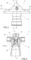
figure 1 shows a perspective view of an air-jet type spinning device according to an embodiment of the present invention; -
figure 2 shows a cross-section view of the air-jet type spinning device infigure 1 , along the cross-section plane II-II infigure 1 ; -
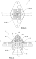
figure 3 shows a cross-section view of the air-jet type spinning device infigure 1 , along the cross-section plane III-III infigure 1 ; -
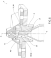
figures 4-5 shows planar and perspective cross-section views of an air-jet type spinning device according to a further embodiment of the present invention; -
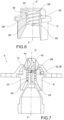
figure 6 shows a perspective view, in partial cross-section, of a body of an air-jet type spinning device according to an embodiment of the present invention; -
figure 7 shows a cross-section view of an air-jet type spinning device according to a further embodiment of the present invention. - The elements or parts of elements common to the embodiments described below will be indicated using the same reference numerals.
- With reference to the aforementioned figures,
reference numeral 4 globally denotes an air-jet type spinning device comprising an at least partiallyhollow body 8 which delimits aspinning chamber 12, and afibre feed device 16, facing saidspinning chamber 12 so as to feed the fibre to thespinning chamber 12. - The
spinning device 4 further comprises aspinning spindle 20 at least partially inserted in thespinning chamber 12 and fitted with aspinning channel 24 for the passage of yarn obtained from said fibres. The spinningchannel 24 defines a spinning direction X-X. - The
spinning device 4 further comprises at least onechannel 28 for sending a jet of compressed air to thespinning chamber 12. - According to the invention, the
spinning chamber 12 is delimited at least partially by an outer side wall 32, opposite thespinning spindle 20, wherein at least onethread 36 is made on said outer side wall 32 and wherein the at least one thread is a spiral thread, , the at least onechannel 28 is oriented so as to direct the jet of compressed air towards the at least onethread 36 in order to be guided and oriented by the latter. In other words, the nozzle is oriented to direct the jet of compressed air towards thethread 36 so that the compressed air, thanks to the Coandeffect, remains substantially adhered to the
thread 36 and lets itself be guided by the latter, moving along the thread inside thespinning chamber 12. - According to one embodiment, the at least one
thread 36 is coaxial with said spinningchannel 24 and parallel to the spinning direction X-X. - This way the compressed air moves according to a spiral motion inside the
spinning chamber 12. - According to one embodiment, the outer side wall 32 of the
spinning chamber 12 comprises twospiral threads 36', 36" coaxial and staggered with each other by 180°, and thespinning device 4 comprises at least twochannels 28', 28", each sending a jet of compressed air to one of saidspiral threads 36', 36". - Preferably, the outer side wall 32 of the
spinning chamber 12 comprises a plurality ofspiral threads 36, and thespinning device 4 comprises the at least onechannel 28 which sends a jet of compressed air to a correspondingspiral thread 36. - According to one embodiment, the
spinning device 4 comprises at least twochannels 28 which send compressed air to respectivedistinct threads 36 and which are staggered with each other with respect to the spinning direction X-X. - It is also possible to provide a
spinning device 4 comprising at least twochannels 28 which direct compressed air into twodistinct emission points 40 of the samespiral thread 36. - According to a possible embodiment, the
channels 28 are directed in a tangential direction T with respect to anemission point 40 in the respectivespiral threads 36. - This condition of tangency facilitates the adhesion of the jet of compressed air to the
thread 36 thanks to the Coandeffect and thus facilitates the proper targeting of the compressed air inside the
spinning chamber 12. - According to one embodiment, the at least one
channel 28 is directed parallel to a horizontal surface O-O, perpendicular to said spinning direction X-X. Even in the condition of the jet of compressed air in theemission point 40 being horizontal, thanks to the presence of thespiral thread 36, the air can deviate downwards, i.e. towards thespinning spindle 20 following the geometry of saidthread 36. There is therefore no need to direct the jets downward as in the solutions of the prior art. - In any case, it is also possible to provide the at least one
channel 28 tilted at a sharp angle with respect to a horizontal plane (O-O), perpendicular to said spinning direction X-X, in a direction moving towards thespinning spindle 20. - According to one embodiment, the at least one
channel 28 is positioned so as to send the relative jet of compressed air to anemission point 40 located downstream of afeed hole 44 of the fibres to thespinning chamber 12, relative to the spinning direction X-X. Thefeed hole 44 is the opening with which thefibre feed device 16 opens onto thespinning chamber 12. - The at least one
thread 36 may have various geometries; preferably it has a curved or semicircular cross-section geometry with a radius ranging between 0.25 mm and 2 mm. - Preferably, the at least one
thread 36 is tilted at a helix angle of 5° to 15°. - Preferably, the pitch of said
thread 36 is between 1.5 mm and 4 mm. - It is possible to use both
fixed pitch thread 36 and variable pitch thread; in addition it is also possible to use both fixed helix angle thread and variable helix angle thread. - The
spinning chamber 12 has an overall cylindrical cross-section with respect to a cross-section plane perpendicular to said spinning direction X-X. It is also possible to use a spinning chamber with a truncated cone cross-section which tapers towards thefibre feed device 16 and widening or flaring toward thespinning spindle 20. - According to one embodiment, the spinning
spindle 20 has an overall cylindrical cross-section with respect to a cross-section plane perpendicular to said spinning direction X-X. - It is also possible to use a spinning
spindle 20 having a truncated cone cross-section which tapers towards thefibre feed device 16. - The
fibre feed device 16 may also comprise aneedle 56 at least partially co-penetrated in saidspinning chamber 12, so as to create a guide for the fibres being spun. The presence of saidneedle 56 is however optional. - As may be appreciated from the description, the air-jet type spinning device according to the invention makes it possible to overcome the drawbacks of the prior art.
- In particular, the present invention allows a significant reduction of air consumption compared to the solutions of the prior art, in the configurations where the number of air injection channels (usually 1 per thread) is less than the conventional number (usually 4).
- In addition, the present invention allows an increase in the size of the spinning chamber and a consequent greater ability to "digest" dirt and fibrils in the spinning process; this way a better yarn quality and greater consistency and repeatability of the characteristics of the yarn obtained is ensured.
- In addition, there is a greater control of the path of the air injected inside the spinning chamber: even in the presence of obstacles (tangled fibres, cotton balls, dirt, etc.) the channel of the outer side wall of the spinning chamber always guides the air the same way. In this case too, a greater regularity of the resulting yarn is ensured.
- Moreover, for the same overall size, an additional space is made on the outer side wall of the spinning chamber, thus increasing the overall size of the spinning chamber. This way the fibres are given more space to "open up" during the spinning process; as a result "longer" windings than with the solutions of the prior art can be obtained.
- In addition, the solution of the present invention, unlike the solutions of the prior art, allows precise control of the path of the compressed air inside the spinning chamber. In fact, as seen, the outer side wall of the spinning chamber may have two suitably sized spirals (pitch and diameter), out of phase by 180° and inclined at a suitable angle which guide the path of the air injected into them from the nozzles. In fact the air, entering tangentially to the channel of the spiral, using the Coandeffect remains adherent to said spiral, thus generating a whirling motion and a given vacuum, in a controlled manner.

- Unlike the solutions of the prior art, it is also possible to enter with the compressed air above the point of entry of the fibres in the spinning chamber, since the airflow does not directly "disturb" the incoming fibres. This is a further advantage, since it prevents interference between the fibres and the air, and thus makes the spinning process more controllable, so as to obtain a yarn with features as constant and repeatable as possible.
- A person skilled in the art may make numerous modifications and variations to the air-jet type spinning devices described above so as to satisfy contingent and specific requirements while remaining within the sphere of protection of the invention as defined by the following claims.
Claims (18)
- Air-jet type spinning device (4) comprising- a body (8) at least partially hollow which delimits a spinning chamber (12)- a fibre feeding device (16), facing said spinning chamber (12) so as to feed the fibres into the spinning chamber (12),- a spinning spindle (20) at least partially inserted in the spinning chamber (12) and fitted with a spinning channel (24) for the transit of yarn obtained from said fibres, the spinning channel (24) defining a spinning direction (X-X),- at least one channel (28) for sending a jet of compressed air inside the spinning chamber (12) wherein- the spinning chamber (12) is delimited at least partially by an outer side wall (32), opposite the spinning spindle (20), wherein at least one thread (36) is made on said outer side wall (32), wherein said at least one thread (36) is a spiral thread,- wherein said at least one channel (28) for sending a jet of compressed air inside the spinning chamber is oriented so as to direct the jet of compressed air towards the at least one thread (36) in order to be guided and oriented by the latter,- wherein the jet of compressed air, thanks to the Coandeffect, remains substantially adhered to the thread (36) and lets itself be guided by the latter, moving along the thread inside the spinning chamber (12).

- Air-jet type spinning device (4) according to claim 1, wherein said at least one thread (36) is a spiral thread, coaxial with said spinning channel (24) and parallel to the spinning direction (X-X).
- Air-jet type spinning device (4) according to claim 1 or 2, wherein the outer side wall (32) of the spinning chamber (12) comprises two spiral threads (36', 36") coaxial and staggered with each other by 180°, and wherein the spinning device (4) comprises at least two channels (28', 28"), each sending a jet of compressed air in one of said spiral threads (36', 36").
- Air-jet type spinning device (4) according to any of the claims from 1 to 3, wherein the outer side wall (32) of the spinning chamber (12) comprises a plurality of spiral threads (36), and wherein the at least one channel (28) sends a jet of compressed air in each corresponding spiral thread (36).
- Air-jet type spinning device (4) according to any of the preceding claims, comprising at least two channels (28) which send compressed air into respective distinct threads (36) which are staggered with each other with respect to the spinning direction (X-X).
- Air-jet type spinning device (4) according to any of the preceding claims, wherein the spinning device (4) comprises at least two channels (28) which send compressed air into two distinct emission points (40) of the same spiral thread (36).
- Air-jet type spinning device (4) according to any of the preceding claims, wherein the channels (28) are oriented in a direction tangential (T), with respect to an emission point (40), to the respective spiral threads (36).
- Air-jet type spinning device (4) according to any of the preceding claims, wherein the at least one channel (28) is oriented parallel to a horizontal plane (O-O) perpendicular to said spinning direction (X-X).
- Air-jet type spinning device (4) according to any of the preceding claims, wherein the at least one channel (28) is tilted at a sharp angle with respect to a horizontal plane (O-O), perpendicular to said spinning direction (X-X), in a direction moving towards the spinning spindle (20).
- Air-jet type spinning device (4) according to any of the preceding claims, wherein the at least one channel is positioned so as to send the relative jet of compressed air to an emission point (20) located upstream of a feed hole (44) of the fibres to the spinning chamber (12), relative to the spinning direction(X-X).
- Air-jet type spinning device (4) according to any of the preceding claims, wherein said at least one thread (36) has curved or semi-circular geometry cross-section.
- Air-jet type spinning device (4) according to claim 11, wherein said at least one thread (36) has curved or semi-circular geometry cross-section with a radius between 0.25 mm and 2 mm.
- Air-jet type spinning device (4) according to any of the preceding claims, wherein said at least one thread (36) is tilted at a helix angle of between 5° and 15°.
- Air-jet type spinning device (4) according to any of the preceding claims, wherein the pitch of said at least one thread (36) is between 1.5 mm and 4 mm.
- Air-jet type spinning device (4) according to any of the preceding claims, wherein said at least one thread (36) is thread with a varying pitch and/or varying helix angle.
- Air-jet type spinning device (4) according to any of the preceding claims, wherein the spinning chamber (12) has overall a cylindrical cross-section with respect to a cross-section plane perpendicular to said spinning direction (X-X).
- Air-jet type spinning device (4) according to any of the preceding claims, wherein the spinning spindle (20) has overall a cylindrical cross-section with respect to a cross-section plane perpendicular to said spinning direction (X-X).
- Air-jet type spinning device (4) according to any of the preceding claims, wherein the fibre feeding device (16) comprises a needle (56), at least partially penetrated in said spinning chamber (12), so as to create a guide for the fibres being spun.
Applications Claiming Priority (1)
| Application Number | Priority Date | Filing Date | Title |
|---|---|---|---|
| ITUA2016A003011A ITUA20163011A1 (en) | 2016-04-29 | 2016-04-29 | AIR-JET TYPE SPINNING DEVICE |
Publications (2)
| Publication Number | Publication Date |
|---|---|
| EP3243941A1 EP3243941A1 (en) | 2017-11-15 |
| EP3243941B1 true EP3243941B1 (en) | 2023-04-05 |
Family
ID=56740378
Family Applications (1)
| Application Number | Title | Priority Date | Filing Date |
|---|---|---|---|
| EP17152644.5A Active EP3243941B1 (en) | 2016-04-29 | 2017-01-23 | Air-jet type spinning device |
Country Status (4)
| Country | Link |
|---|---|
| US (1) | US10597799B2 (en) |
| EP (1) | EP3243941B1 (en) |
| CN (2) | CN206553676U (en) |
| IT (1) | ITUA20163011A1 (en) |
Families Citing this family (5)
| Publication number | Priority date | Publication date | Assignee | Title |
|---|---|---|---|---|
| ITUA20163011A1 (en) * | 2016-04-29 | 2017-10-29 | Savio Macch Tessili Spa | AIR-JET TYPE SPINNING DEVICE |
| IT201800009728A1 (en) | 2018-10-24 | 2020-04-24 | Savio Macch Tessili Spa | AIR-JET TYPE SPINNING DEVICE |
| DE102020109170A1 (en) * | 2020-04-02 | 2021-10-07 | Maschinenfabrik Rieter Ag | Twist element for a spinneret of an air-jet spinning machine as well as work station of an air-jet spinning machine |
| DE102020133359A1 (en) * | 2020-12-14 | 2022-06-15 | Saurer Spinning Solutions Gmbh & Co. Kg | Multifunction nozzle for a spinning machine |
| DE102022114064A1 (en) | 2022-06-03 | 2023-12-14 | Saurer Spinning Solutions Gmbh & Co. Kg | Thread take-off nozzle and open-end spinning device with a thread take-off nozzle |
Citations (1)
| Publication number | Priority date | Publication date | Assignee | Title |
|---|---|---|---|---|
| JPH04131663U (en) * | 1991-05-22 | 1992-12-03 | 村田機械株式会社 | spinning equipment |
Family Cites Families (27)
| Publication number | Priority date | Publication date | Assignee | Title |
|---|---|---|---|---|
| GB1200669A (en) * | 1966-12-29 | 1970-07-29 | Mitsubishi Rayon Co | High speed spinning method and apparatus for manufacturing jet bundle yarn |
| DE2049186C3 (en) * | 1970-10-07 | 1980-09-18 | Konrad 8902 Goeggingen Goetzfried | Method and apparatus for producing a yarn |
| US4242859A (en) * | 1980-01-21 | 1981-01-06 | Lawrence M. Keeler | Thread spinning apparatus |
| US4457130A (en) * | 1981-10-13 | 1984-07-03 | Murata Kikai Kabushiki Kaisha | Air spinning nozzle unit |
| JPS61186531A (en) * | 1985-02-15 | 1986-08-20 | Toyoda Autom Loom Works Ltd | Nozzle for fasciated spinning |
| DE3732708A1 (en) * | 1987-01-15 | 1988-07-28 | Stahlecker Fritz | AIR NOZZLE FOR PNEUMATIC SPIRAL SPINNING WITH A THREAD CHANNEL MADE OF AT LEAST TWO SECTIONS |
| EP0418693A1 (en) * | 1989-09-21 | 1991-03-27 | Maschinenfabrik Rieter Ag | Nozzle of an air jet spinning machine |
| JPH0465535A (en) * | 1990-07-04 | 1992-03-02 | Murata Mach Ltd | Spinning machine |
| US5169071A (en) * | 1990-09-06 | 1992-12-08 | Nordson Corporation | Nozzle cap for an adhesive dispenser |
| JPH0674530B2 (en) * | 1991-07-30 | 1994-09-21 | 村田機械株式会社 | Spinning equipment |
| JPH07122167B2 (en) * | 1992-03-16 | 1995-12-25 | 村田機械株式会社 | Yarn splicing method for spinning device |
| CN1092828A (en) * | 1993-03-19 | 1994-09-28 | 里特因戈尔斯塔特纺纱机械制造有限公司 | The method and apparatus of air spinning yarn |
| JP2697575B2 (en) * | 1993-09-08 | 1998-01-14 | 村田機械株式会社 | Spinning equipment |
| JPH08226037A (en) * | 1995-02-22 | 1996-09-03 | Murata Mach Ltd | Interlaced nozzle |
| US7059110B2 (en) * | 2000-09-22 | 2006-06-13 | Maschinenfabrik Rieter Ag | Spinning device for production of spun thread from a fibre sliver |
| ATE304620T1 (en) * | 2001-08-17 | 2005-09-15 | Rieter Ag Maschf | DEVICE FOR PRODUCING A SPUN YARN |
| DE10346226A1 (en) * | 2003-09-23 | 2005-04-14 | Wilhelm Stahlecker Gmbh | Yarn-forming spindle for air vortex spinner is mounted on compressed air cylinder to allow it to retract to give better access for cleaning |
| DE102005045703A1 (en) * | 2005-09-19 | 2007-03-22 | Wilhelm Stahlecker Gmbh | Air jet unit for an air jet spinning device |
| DE102006018249A1 (en) * | 2006-04-13 | 2007-10-18 | Wilhelm Stahlecker Gmbh | Spindle-shaped component for an air jet spinning device with an injection channel |
| CN102304788B (en) * | 2007-06-04 | 2014-07-30 | 村田机械株式会社 | Spinning device |
| DE102012101001A1 (en) * | 2012-02-08 | 2013-08-08 | Maschinenfabrik Rieter Ag | Garnbildungselement for a spinning station of an air-spinning machine with a helical guide and method for producing a yarn |
| JP6031847B2 (en) * | 2012-06-22 | 2016-11-24 | 村田機械株式会社 | Hollow guide shaft body, pneumatic spinning device, and yarn winding machine including the same |
| DE102012110315A1 (en) * | 2012-10-29 | 2014-04-30 | Maschinenfabrik Rieter Ag | Garnbildungselement for an air-spinning machine with an insert and spinneret equipped therewith |
| CN103603094B (en) * | 2013-08-05 | 2015-12-09 | 东华大学 | A kind of air injection air vortex spinning apparatus of side entrance |
| CN103603095B (en) * | 2013-11-11 | 2015-12-09 | 东华大学 | The configuration structure in jet-impingement hole in a kind of air injection air vortex spinning apparatus |
| ITUA20163011A1 (en) * | 2016-04-29 | 2017-10-29 | Savio Macch Tessili Spa | AIR-JET TYPE SPINNING DEVICE |
| KR102034766B1 (en) * | 2018-04-12 | 2019-10-22 | 주식회사 유진테크 | Apparatus for processing substrate and method for processing substrate |
-
2016
- 2016-04-29 IT ITUA2016A003011A patent/ITUA20163011A1/en unknown
-
2017
- 2017-01-23 EP EP17152644.5A patent/EP3243941B1/en active Active
- 2017-03-03 CN CN201720206968.9U patent/CN206553676U/en not_active Withdrawn - After Issue
- 2017-03-03 CN CN201710124144.1A patent/CN107338518B/en active Active
- 2017-04-28 US US15/582,094 patent/US10597799B2/en active Active
Patent Citations (1)
| Publication number | Priority date | Publication date | Assignee | Title |
|---|---|---|---|---|
| JPH04131663U (en) * | 1991-05-22 | 1992-12-03 | 村田機械株式会社 | spinning equipment |
Also Published As
| Publication number | Publication date |
|---|---|
| CN107338518A (en) | 2017-11-10 |
| ITUA20163011A1 (en) | 2017-10-29 |
| CN206553676U (en) | 2017-10-13 |
| US10597799B2 (en) | 2020-03-24 |
| US20170314166A1 (en) | 2017-11-02 |
| EP3243941A1 (en) | 2017-11-15 |
| CN107338518B (en) | 2024-11-19 |
Similar Documents
| Publication | Publication Date | Title |
|---|---|---|
| US10597799B2 (en) | Air-jet type spinning device | |
| EP3243942B1 (en) | Air-jet type spinning device | |
| CN101268222A (en) | Air nozzle assembly for an air jet spinning device | |
| US9670599B2 (en) | Spinning station of an air jet spinning machine | |
| US9677197B2 (en) | Spinning station of a spinning preparation machine | |
| EP3643818B1 (en) | Air-jet type spinning device | |
| CN103603094B (en) | A kind of air injection air vortex spinning apparatus of side entrance | |
| EP2369042B1 (en) | Pneumatic spinning device and spinning machine | |
| JP5698232B2 (en) | Pneumatic spinning equipment | |
| EP3266910B1 (en) | Air-jet type spinning device | |
| US7080502B2 (en) | Arrangement for producing a spun thread | |
| US9243352B2 (en) | Spinning nozzle and spinning station of an air-jet spinning machine fitted therewith | |
| EP2369044B1 (en) | Pneumatic spinning device and spinning machine | |
| CN105765119B (en) | Fiber guiding element and spinning station of an air-jet spinning machine for producing yarn from fiber bundles | |
| US6679044B2 (en) | Pneumatic spinning apparatus | |
| CN111411426B (en) | Fiber guiding element for a spinneret and spinneret provided with said fiber guiding element | |
| CN109154110A (en) | Yarn for fly frame forms element and is equipped with the fly frame that yarn forms element | |
| IL25990A (en) | Pneumatic false twister | |
| CN1970859B (en) | Spinning apparatus | |
| US10167577B2 (en) | Channel plate adapter and open-end spinning device with a channel plate adapter | |
| US20080115476A1 (en) | Air Jet Spinning Arrangement | |
| CS266666B1 (en) | Equipment for bundled yarn production in pneumatic spinning nozzle | |
| JPH02112422A (en) | Friction spinning device | |
| JPS60162852A (en) | Fiber web producing apparatus |
Legal Events
| Date | Code | Title | Description |
|---|---|---|---|
| PUAI | Public reference made under article 153(3) epc to a published international application that has entered the european phase |
Free format text: ORIGINAL CODE: 0009012 |
|
| STAA | Information on the status of an ep patent application or granted ep patent |
Free format text: STATUS: THE APPLICATION HAS BEEN PUBLISHED |
|
| AK | Designated contracting states |
Kind code of ref document: A1 Designated state(s): AL AT BE BG CH CY CZ DE DK EE ES FI FR GB GR HR HU IE IS IT LI LT LU LV MC MK MT NL NO PL PT RO RS SE SI SK SM TR |
|
| AX | Request for extension of the european patent |
Extension state: BA ME |
|
| STAA | Information on the status of an ep patent application or granted ep patent |
Free format text: STATUS: REQUEST FOR EXAMINATION WAS MADE |
|
| 17P | Request for examination filed |
Effective date: 20180514 |
|
| RBV | Designated contracting states (corrected) |
Designated state(s): AL AT BE BG CH CY CZ DE DK EE ES FI FR GB GR HR HU IE IS IT LI LT LU LV MC MK MT NL NO PL PT RO RS SE SI SK SM TR |
|
| RAP1 | Party data changed (applicant data changed or rights of an application transferred) |
Owner name: SAVIO MACCHINE TESSILI S.P.A. |
|
| STAA | Information on the status of an ep patent application or granted ep patent |
Free format text: STATUS: EXAMINATION IS IN PROGRESS |
|
| 17Q | First examination report despatched |
Effective date: 20210324 |
|
| GRAP | Despatch of communication of intention to grant a patent |
Free format text: ORIGINAL CODE: EPIDOSNIGR1 |
|
| STAA | Information on the status of an ep patent application or granted ep patent |
Free format text: STATUS: GRANT OF PATENT IS INTENDED |
|
| INTG | Intention to grant announced |
Effective date: 20221129 |
|
| GRAS | Grant fee paid |
Free format text: ORIGINAL CODE: EPIDOSNIGR3 |
|
| GRAA | (expected) grant |
Free format text: ORIGINAL CODE: 0009210 |
|
| STAA | Information on the status of an ep patent application or granted ep patent |
Free format text: STATUS: THE PATENT HAS BEEN GRANTED |
|
| AK | Designated contracting states |
Kind code of ref document: B1 Designated state(s): AL AT BE BG CH CY CZ DE DK EE ES FI FR GB GR HR HU IE IS IT LI LT LU LV MC MK MT NL NO PL PT RO RS SE SI SK SM TR |
|
| REG | Reference to a national code |
Ref country code: GB Ref legal event code: FG4D |
|
| REG | Reference to a national code |
Ref country code: DE Ref legal event code: R096 Ref document number: 602017067368 Country of ref document: DE |
|
| REG | Reference to a national code |
Ref country code: CH Ref legal event code: EP |
|
| REG | Reference to a national code |
Ref country code: AT Ref legal event code: REF Ref document number: 1558319 Country of ref document: AT Kind code of ref document: T Effective date: 20230415 |
|
| REG | Reference to a national code |
Ref country code: IE Ref legal event code: FG4D |
|
| P01 | Opt-out of the competence of the unified patent court (upc) registered |
Effective date: 20230526 |
|
| REG | Reference to a national code |
Ref country code: LT Ref legal event code: MG9D |
|
| REG | Reference to a national code |
Ref country code: NL Ref legal event code: MP Effective date: 20230405 |
|
| REG | Reference to a national code |
Ref country code: AT Ref legal event code: MK05 Ref document number: 1558319 Country of ref document: AT Kind code of ref document: T Effective date: 20230405 |
|
| PG25 | Lapsed in a contracting state [announced via postgrant information from national office to epo] |
Ref country code: NL Free format text: LAPSE BECAUSE OF FAILURE TO SUBMIT A TRANSLATION OF THE DESCRIPTION OR TO PAY THE FEE WITHIN THE PRESCRIBED TIME-LIMIT Effective date: 20230405 |
|
| PG25 | Lapsed in a contracting state [announced via postgrant information from national office to epo] |
Ref country code: SE Free format text: LAPSE BECAUSE OF FAILURE TO SUBMIT A TRANSLATION OF THE DESCRIPTION OR TO PAY THE FEE WITHIN THE PRESCRIBED TIME-LIMIT Effective date: 20230405 Ref country code: PT Free format text: LAPSE BECAUSE OF FAILURE TO SUBMIT A TRANSLATION OF THE DESCRIPTION OR TO PAY THE FEE WITHIN THE PRESCRIBED TIME-LIMIT Effective date: 20230807 Ref country code: NO Free format text: LAPSE BECAUSE OF FAILURE TO SUBMIT A TRANSLATION OF THE DESCRIPTION OR TO PAY THE FEE WITHIN THE PRESCRIBED TIME-LIMIT Effective date: 20230705 Ref country code: ES Free format text: LAPSE BECAUSE OF FAILURE TO SUBMIT A TRANSLATION OF THE DESCRIPTION OR TO PAY THE FEE WITHIN THE PRESCRIBED TIME-LIMIT Effective date: 20230405 Ref country code: AT Free format text: LAPSE BECAUSE OF FAILURE TO SUBMIT A TRANSLATION OF THE DESCRIPTION OR TO PAY THE FEE WITHIN THE PRESCRIBED TIME-LIMIT Effective date: 20230405 |
|
| PG25 | Lapsed in a contracting state [announced via postgrant information from national office to epo] |
Ref country code: RS Free format text: LAPSE BECAUSE OF FAILURE TO SUBMIT A TRANSLATION OF THE DESCRIPTION OR TO PAY THE FEE WITHIN THE PRESCRIBED TIME-LIMIT Effective date: 20230405 Ref country code: PL Free format text: LAPSE BECAUSE OF FAILURE TO SUBMIT A TRANSLATION OF THE DESCRIPTION OR TO PAY THE FEE WITHIN THE PRESCRIBED TIME-LIMIT Effective date: 20230405 Ref country code: LV Free format text: LAPSE BECAUSE OF FAILURE TO SUBMIT A TRANSLATION OF THE DESCRIPTION OR TO PAY THE FEE WITHIN THE PRESCRIBED TIME-LIMIT Effective date: 20230405 Ref country code: LT Free format text: LAPSE BECAUSE OF FAILURE TO SUBMIT A TRANSLATION OF THE DESCRIPTION OR TO PAY THE FEE WITHIN THE PRESCRIBED TIME-LIMIT Effective date: 20230405 Ref country code: IS Free format text: LAPSE BECAUSE OF FAILURE TO SUBMIT A TRANSLATION OF THE DESCRIPTION OR TO PAY THE FEE WITHIN THE PRESCRIBED TIME-LIMIT Effective date: 20230805 Ref country code: HR Free format text: LAPSE BECAUSE OF FAILURE TO SUBMIT A TRANSLATION OF THE DESCRIPTION OR TO PAY THE FEE WITHIN THE PRESCRIBED TIME-LIMIT Effective date: 20230405 Ref country code: GR Free format text: LAPSE BECAUSE OF FAILURE TO SUBMIT A TRANSLATION OF THE DESCRIPTION OR TO PAY THE FEE WITHIN THE PRESCRIBED TIME-LIMIT Effective date: 20230706 Ref country code: AL Free format text: LAPSE BECAUSE OF FAILURE TO SUBMIT A TRANSLATION OF THE DESCRIPTION OR TO PAY THE FEE WITHIN THE PRESCRIBED TIME-LIMIT Effective date: 20230405 |
|
| PG25 | Lapsed in a contracting state [announced via postgrant information from national office to epo] |
Ref country code: FI Free format text: LAPSE BECAUSE OF FAILURE TO SUBMIT A TRANSLATION OF THE DESCRIPTION OR TO PAY THE FEE WITHIN THE PRESCRIBED TIME-LIMIT Effective date: 20230405 |
|
| REG | Reference to a national code |
Ref country code: DE Ref legal event code: R097 Ref document number: 602017067368 Country of ref document: DE |
|
| PG25 | Lapsed in a contracting state [announced via postgrant information from national office to epo] |
Ref country code: SK Free format text: LAPSE BECAUSE OF FAILURE TO SUBMIT A TRANSLATION OF THE DESCRIPTION OR TO PAY THE FEE WITHIN THE PRESCRIBED TIME-LIMIT Effective date: 20230405 |
|
| PG25 | Lapsed in a contracting state [announced via postgrant information from national office to epo] |
Ref country code: SM Free format text: LAPSE BECAUSE OF FAILURE TO SUBMIT A TRANSLATION OF THE DESCRIPTION OR TO PAY THE FEE WITHIN THE PRESCRIBED TIME-LIMIT Effective date: 20230405 Ref country code: SK Free format text: LAPSE BECAUSE OF FAILURE TO SUBMIT A TRANSLATION OF THE DESCRIPTION OR TO PAY THE FEE WITHIN THE PRESCRIBED TIME-LIMIT Effective date: 20230405 Ref country code: RO Free format text: LAPSE BECAUSE OF FAILURE TO SUBMIT A TRANSLATION OF THE DESCRIPTION OR TO PAY THE FEE WITHIN THE PRESCRIBED TIME-LIMIT Effective date: 20230405 Ref country code: EE Free format text: LAPSE BECAUSE OF FAILURE TO SUBMIT A TRANSLATION OF THE DESCRIPTION OR TO PAY THE FEE WITHIN THE PRESCRIBED TIME-LIMIT Effective date: 20230405 Ref country code: DK Free format text: LAPSE BECAUSE OF FAILURE TO SUBMIT A TRANSLATION OF THE DESCRIPTION OR TO PAY THE FEE WITHIN THE PRESCRIBED TIME-LIMIT Effective date: 20230405 Ref country code: CZ Free format text: LAPSE BECAUSE OF FAILURE TO SUBMIT A TRANSLATION OF THE DESCRIPTION OR TO PAY THE FEE WITHIN THE PRESCRIBED TIME-LIMIT Effective date: 20230405 |
|
| PLBE | No opposition filed within time limit |
Free format text: ORIGINAL CODE: 0009261 |
|
| STAA | Information on the status of an ep patent application or granted ep patent |
Free format text: STATUS: NO OPPOSITION FILED WITHIN TIME LIMIT |
|
| 26N | No opposition filed |
Effective date: 20240108 |
|
| PG25 | Lapsed in a contracting state [announced via postgrant information from national office to epo] |
Ref country code: SI Free format text: LAPSE BECAUSE OF FAILURE TO SUBMIT A TRANSLATION OF THE DESCRIPTION OR TO PAY THE FEE WITHIN THE PRESCRIBED TIME-LIMIT Effective date: 20230405 |
|
| PG25 | Lapsed in a contracting state [announced via postgrant information from national office to epo] |
Ref country code: SI Free format text: LAPSE BECAUSE OF FAILURE TO SUBMIT A TRANSLATION OF THE DESCRIPTION OR TO PAY THE FEE WITHIN THE PRESCRIBED TIME-LIMIT Effective date: 20230405 |
|
| REG | Reference to a national code |
Ref country code: DE Ref legal event code: R119 Ref document number: 602017067368 Country of ref document: DE |
|
| PG25 | Lapsed in a contracting state [announced via postgrant information from national office to epo] |
Ref country code: MC Free format text: LAPSE BECAUSE OF FAILURE TO SUBMIT A TRANSLATION OF THE DESCRIPTION OR TO PAY THE FEE WITHIN THE PRESCRIBED TIME-LIMIT Effective date: 20230405 |
|
| PG25 | Lapsed in a contracting state [announced via postgrant information from national office to epo] |
Ref country code: MC Free format text: LAPSE BECAUSE OF FAILURE TO SUBMIT A TRANSLATION OF THE DESCRIPTION OR TO PAY THE FEE WITHIN THE PRESCRIBED TIME-LIMIT Effective date: 20230405 |
|
| REG | Reference to a national code |
Ref country code: CH Ref legal event code: PL |
|
| PG25 | Lapsed in a contracting state [announced via postgrant information from national office to epo] |
Ref country code: LU Free format text: LAPSE BECAUSE OF NON-PAYMENT OF DUE FEES Effective date: 20240123 |
|
| GBPC | Gb: european patent ceased through non-payment of renewal fee |
Effective date: 20240123 |
|
| PG25 | Lapsed in a contracting state [announced via postgrant information from national office to epo] |
Ref country code: LU Free format text: LAPSE BECAUSE OF NON-PAYMENT OF DUE FEES Effective date: 20240123 |
|
| PG25 | Lapsed in a contracting state [announced via postgrant information from national office to epo] |
Ref country code: DE Free format text: LAPSE BECAUSE OF NON-PAYMENT OF DUE FEES Effective date: 20240801 |
|
| PG25 | Lapsed in a contracting state [announced via postgrant information from national office to epo] |
Ref country code: GB Free format text: LAPSE BECAUSE OF NON-PAYMENT OF DUE FEES Effective date: 20240123 |
|
| PG25 | Lapsed in a contracting state [announced via postgrant information from national office to epo] |
Ref country code: BE Free format text: LAPSE BECAUSE OF NON-PAYMENT OF DUE FEES Effective date: 20240131 |
|
| PG25 | Lapsed in a contracting state [announced via postgrant information from national office to epo] |
Ref country code: FR Free format text: LAPSE BECAUSE OF NON-PAYMENT OF DUE FEES Effective date: 20240131 |
|
| PG25 | Lapsed in a contracting state [announced via postgrant information from national office to epo] |
Ref country code: CH Free format text: LAPSE BECAUSE OF NON-PAYMENT OF DUE FEES Effective date: 20240131 |
|
| PG25 | Lapsed in a contracting state [announced via postgrant information from national office to epo] |
Ref country code: GB Free format text: LAPSE BECAUSE OF NON-PAYMENT OF DUE FEES Effective date: 20240123 Ref country code: FR Free format text: LAPSE BECAUSE OF NON-PAYMENT OF DUE FEES Effective date: 20240131 Ref country code: DE Free format text: LAPSE BECAUSE OF NON-PAYMENT OF DUE FEES Effective date: 20240801 Ref country code: CH Free format text: LAPSE BECAUSE OF NON-PAYMENT OF DUE FEES Effective date: 20240131 Ref country code: BE Free format text: LAPSE BECAUSE OF NON-PAYMENT OF DUE FEES Effective date: 20240131 |
|
| REG | Reference to a national code |
Ref country code: BE Ref legal event code: MM Effective date: 20240131 |
|
| PG25 | Lapsed in a contracting state [announced via postgrant information from national office to epo] |
Ref country code: BG Free format text: LAPSE BECAUSE OF FAILURE TO SUBMIT A TRANSLATION OF THE DESCRIPTION OR TO PAY THE FEE WITHIN THE PRESCRIBED TIME-LIMIT Effective date: 20230405 |
|
| PG25 | Lapsed in a contracting state [announced via postgrant information from national office to epo] |
Ref country code: BG Free format text: LAPSE BECAUSE OF FAILURE TO SUBMIT A TRANSLATION OF THE DESCRIPTION OR TO PAY THE FEE WITHIN THE PRESCRIBED TIME-LIMIT Effective date: 20230405 |
|
| PG25 | Lapsed in a contracting state [announced via postgrant information from national office to epo] |
Ref country code: IE Free format text: LAPSE BECAUSE OF NON-PAYMENT OF DUE FEES Effective date: 20240123 |
|
| PG25 | Lapsed in a contracting state [announced via postgrant information from national office to epo] |
Ref country code: IE Free format text: LAPSE BECAUSE OF NON-PAYMENT OF DUE FEES Effective date: 20240123 |
|
| PG25 | Lapsed in a contracting state [announced via postgrant information from national office to epo] |
Ref country code: CY Free format text: LAPSE BECAUSE OF FAILURE TO SUBMIT A TRANSLATION OF THE DESCRIPTION OR TO PAY THE FEE WITHIN THE PRESCRIBED TIME-LIMIT; INVALID AB INITIO Effective date: 20170123 |
|
| PG25 | Lapsed in a contracting state [announced via postgrant information from national office to epo] |
Ref country code: HU Free format text: LAPSE BECAUSE OF FAILURE TO SUBMIT A TRANSLATION OF THE DESCRIPTION OR TO PAY THE FEE WITHIN THE PRESCRIBED TIME-LIMIT; INVALID AB INITIO Effective date: 20170123 |
|
| PGFP | Annual fee paid to national office [announced via postgrant information from national office to epo] |
Ref country code: IT Payment date: 20251218 Year of fee payment: 10 |
|
| PGFP | Annual fee paid to national office [announced via postgrant information from national office to epo] |
Ref country code: TR Payment date: 20260123 Year of fee payment: 10 |