EP3243753A1 - Thrust force generation device and aircraft - Google Patents
Thrust force generation device and aircraft Download PDFInfo
- Publication number
- EP3243753A1 EP3243753A1 EP16755514.3A EP16755514A EP3243753A1 EP 3243753 A1 EP3243753 A1 EP 3243753A1 EP 16755514 A EP16755514 A EP 16755514A EP 3243753 A1 EP3243753 A1 EP 3243753A1
- Authority
- EP
- European Patent Office
- Prior art keywords
- unit
- thrust
- fan
- generation device
- force generation
- Prior art date
- Legal status (The legal status is an assumption and is not a legal conclusion. Google has not performed a legal analysis and makes no representation as to the accuracy of the status listed.)
- Granted
Links
Images


Classifications
-
- B—PERFORMING OPERATIONS; TRANSPORTING
- B64—AIRCRAFT; AVIATION; COSMONAUTICS
- B64D—EQUIPMENT FOR FITTING IN OR TO AIRCRAFT; FLIGHT SUITS; PARACHUTES; ARRANGEMENT OR MOUNTING OF POWER PLANTS OR PROPULSION TRANSMISSIONS IN AIRCRAFT
- B64D27/00—Arrangement or mounting of power plants in aircraft; Aircraft characterised by the type or position of power plants
- B64D27/02—Aircraft characterised by the type or position of power plants
- B64D27/16—Aircraft characterised by the type or position of power plants of jet type
- B64D27/18—Aircraft characterised by the type or position of power plants of jet type within, or attached to, wings
-
- B—PERFORMING OPERATIONS; TRANSPORTING
- B64—AIRCRAFT; AVIATION; COSMONAUTICS
- B64D—EQUIPMENT FOR FITTING IN OR TO AIRCRAFT; FLIGHT SUITS; PARACHUTES; ARRANGEMENT OR MOUNTING OF POWER PLANTS OR PROPULSION TRANSMISSIONS IN AIRCRAFT
- B64D27/00—Arrangement or mounting of power plants in aircraft; Aircraft characterised by the type or position of power plants
- B64D27/02—Aircraft characterised by the type or position of power plants
- B64D27/24—Aircraft characterised by the type or position of power plants using steam or spring force
-
- B—PERFORMING OPERATIONS; TRANSPORTING
- B64—AIRCRAFT; AVIATION; COSMONAUTICS
- B64D—EQUIPMENT FOR FITTING IN OR TO AIRCRAFT; FLIGHT SUITS; PARACHUTES; ARRANGEMENT OR MOUNTING OF POWER PLANTS OR PROPULSION TRANSMISSIONS IN AIRCRAFT
- B64D27/00—Arrangement or mounting of power plants in aircraft; Aircraft characterised by the type or position of power plants
- B64D27/02—Aircraft characterised by the type or position of power plants
- B64D27/10—Aircraft characterised by the type or position of power plants of gas-turbine type
- B64D27/12—Aircraft characterised by the type or position of power plants of gas-turbine type within, or attached to, wings
-
- B—PERFORMING OPERATIONS; TRANSPORTING
- B64—AIRCRAFT; AVIATION; COSMONAUTICS
- B64D—EQUIPMENT FOR FITTING IN OR TO AIRCRAFT; FLIGHT SUITS; PARACHUTES; ARRANGEMENT OR MOUNTING OF POWER PLANTS OR PROPULSION TRANSMISSIONS IN AIRCRAFT
- B64D27/00—Arrangement or mounting of power plants in aircraft; Aircraft characterised by the type or position of power plants
- B64D27/02—Aircraft characterised by the type or position of power plants
- B64D27/30—Aircraft characterised by electric power plants
- B64D27/31—Aircraft characterised by electric power plants within, or attached to, wings
-
- B—PERFORMING OPERATIONS; TRANSPORTING
- B64—AIRCRAFT; AVIATION; COSMONAUTICS
- B64D—EQUIPMENT FOR FITTING IN OR TO AIRCRAFT; FLIGHT SUITS; PARACHUTES; ARRANGEMENT OR MOUNTING OF POWER PLANTS OR PROPULSION TRANSMISSIONS IN AIRCRAFT
- B64D27/00—Arrangement or mounting of power plants in aircraft; Aircraft characterised by the type or position of power plants
- B64D27/02—Aircraft characterised by the type or position of power plants
- B64D27/30—Aircraft characterised by electric power plants
- B64D27/33—Hybrid electric aircraft
-
- B—PERFORMING OPERATIONS; TRANSPORTING
- B64—AIRCRAFT; AVIATION; COSMONAUTICS
- B64D—EQUIPMENT FOR FITTING IN OR TO AIRCRAFT; FLIGHT SUITS; PARACHUTES; ARRANGEMENT OR MOUNTING OF POWER PLANTS OR PROPULSION TRANSMISSIONS IN AIRCRAFT
- B64D27/00—Arrangement or mounting of power plants in aircraft; Aircraft characterised by the type or position of power plants
- B64D27/40—Arrangements for mounting power plants in aircraft
- B64D27/402—Arrangements for mounting power plants in aircraft comprising box like supporting frames, e.g. pylons or arrangements for embracing the power plant
-
- B—PERFORMING OPERATIONS; TRANSPORTING
- B64—AIRCRAFT; AVIATION; COSMONAUTICS
- B64D—EQUIPMENT FOR FITTING IN OR TO AIRCRAFT; FLIGHT SUITS; PARACHUTES; ARRANGEMENT OR MOUNTING OF POWER PLANTS OR PROPULSION TRANSMISSIONS IN AIRCRAFT
- B64D27/00—Arrangement or mounting of power plants in aircraft; Aircraft characterised by the type or position of power plants
- B64D27/40—Arrangements for mounting power plants in aircraft
- B64D27/404—Suspension arrangements specially adapted for supporting vertical loads
-
- B—PERFORMING OPERATIONS; TRANSPORTING
- B64—AIRCRAFT; AVIATION; COSMONAUTICS
- B64D—EQUIPMENT FOR FITTING IN OR TO AIRCRAFT; FLIGHT SUITS; PARACHUTES; ARRANGEMENT OR MOUNTING OF POWER PLANTS OR PROPULSION TRANSMISSIONS IN AIRCRAFT
- B64D27/00—Arrangement or mounting of power plants in aircraft; Aircraft characterised by the type or position of power plants
- B64D27/40—Arrangements for mounting power plants in aircraft
- B64D27/406—Suspension arrangements specially adapted for supporting thrust loads, e.g. thrust links
-
- B—PERFORMING OPERATIONS; TRANSPORTING
- B64—AIRCRAFT; AVIATION; COSMONAUTICS
- B64D—EQUIPMENT FOR FITTING IN OR TO AIRCRAFT; FLIGHT SUITS; PARACHUTES; ARRANGEMENT OR MOUNTING OF POWER PLANTS OR PROPULSION TRANSMISSIONS IN AIRCRAFT
- B64D35/00—Transmitting power from power plants to propellers or rotors; Arrangements of transmissions
- B64D35/04—Transmitting power from power plants to propellers or rotors; Arrangements of transmissions characterised by the transmission driving a plurality of propellers or rotors
-
- F—MECHANICAL ENGINEERING; LIGHTING; HEATING; WEAPONS; BLASTING
- F02—COMBUSTION ENGINES; HOT-GAS OR COMBUSTION-PRODUCT ENGINE PLANTS
- F02C—GAS-TURBINE PLANTS; AIR INTAKES FOR JET-PROPULSION PLANTS; CONTROLLING FUEL SUPPLY IN AIR-BREATHING JET-PROPULSION PLANTS
- F02C6/00—Plural gas-turbine plants; Combinations of gas-turbine plants with other apparatus; Adaptations of gas-turbine plants for special use
-
- F—MECHANICAL ENGINEERING; LIGHTING; HEATING; WEAPONS; BLASTING
- F02—COMBUSTION ENGINES; HOT-GAS OR COMBUSTION-PRODUCT ENGINE PLANTS
- F02C—GAS-TURBINE PLANTS; AIR INTAKES FOR JET-PROPULSION PLANTS; CONTROLLING FUEL SUPPLY IN AIR-BREATHING JET-PROPULSION PLANTS
- F02C7/00—Features, components parts, details or accessories, not provided for in, or of interest apart form groups F02C1/00 - F02C6/00; Air intakes for jet-propulsion plants
- F02C7/20—Mounting or supporting of plant; Accommodating heat expansion or creep
-
- F—MECHANICAL ENGINEERING; LIGHTING; HEATING; WEAPONS; BLASTING
- F02—COMBUSTION ENGINES; HOT-GAS OR COMBUSTION-PRODUCT ENGINE PLANTS
- F02K—JET-PROPULSION PLANTS
- F02K3/00—Plants including a gas turbine driving a compressor or a ducted fan
- F02K3/02—Plants including a gas turbine driving a compressor or a ducted fan in which part of the working fluid by-passes the turbine and combustion chamber
- F02K3/04—Plants including a gas turbine driving a compressor or a ducted fan in which part of the working fluid by-passes the turbine and combustion chamber the plant including ducted fans, i.e. fans with high volume, low pressure outputs, for augmenting the jet thrust, e.g. of double-flow type
- F02K3/06—Plants including a gas turbine driving a compressor or a ducted fan in which part of the working fluid by-passes the turbine and combustion chamber the plant including ducted fans, i.e. fans with high volume, low pressure outputs, for augmenting the jet thrust, e.g. of double-flow type with front fan
-
- F—MECHANICAL ENGINEERING; LIGHTING; HEATING; WEAPONS; BLASTING
- F02—COMBUSTION ENGINES; HOT-GAS OR COMBUSTION-PRODUCT ENGINE PLANTS
- F02K—JET-PROPULSION PLANTS
- F02K5/00—Plants including an engine, other than a gas turbine, driving a compressor or a ducted fan
-
- B—PERFORMING OPERATIONS; TRANSPORTING
- B64—AIRCRAFT; AVIATION; COSMONAUTICS
- B64D—EQUIPMENT FOR FITTING IN OR TO AIRCRAFT; FLIGHT SUITS; PARACHUTES; ARRANGEMENT OR MOUNTING OF POWER PLANTS OR PROPULSION TRANSMISSIONS IN AIRCRAFT
- B64D27/00—Arrangement or mounting of power plants in aircraft; Aircraft characterised by the type or position of power plants
- B64D27/02—Aircraft characterised by the type or position of power plants
- B64D27/026—Aircraft characterised by the type or position of power plants comprising different types of power plants, e.g. combination of a piston engine and a gas-turbine
-
- F—MECHANICAL ENGINEERING; LIGHTING; HEATING; WEAPONS; BLASTING
- F02—COMBUSTION ENGINES; HOT-GAS OR COMBUSTION-PRODUCT ENGINE PLANTS
- F02C—GAS-TURBINE PLANTS; AIR INTAKES FOR JET-PROPULSION PLANTS; CONTROLLING FUEL SUPPLY IN AIR-BREATHING JET-PROPULSION PLANTS
- F02C3/00—Gas-turbine plants characterised by the use of combustion products as the working fluid
- F02C3/04—Gas-turbine plants characterised by the use of combustion products as the working fluid having a turbine driving a compressor
-
- F—MECHANICAL ENGINEERING; LIGHTING; HEATING; WEAPONS; BLASTING
- F05—INDEXING SCHEMES RELATING TO ENGINES OR PUMPS IN VARIOUS SUBCLASSES OF CLASSES F01-F04
- F05D—INDEXING SCHEME FOR ASPECTS RELATING TO NON-POSITIVE-DISPLACEMENT MACHINES OR ENGINES, GAS-TURBINES OR JET-PROPULSION PLANTS
- F05D2220/00—Application
- F05D2220/30—Application in turbines
- F05D2220/32—Application in turbines in gas turbines
-
- F—MECHANICAL ENGINEERING; LIGHTING; HEATING; WEAPONS; BLASTING
- F05—INDEXING SCHEMES RELATING TO ENGINES OR PUMPS IN VARIOUS SUBCLASSES OF CLASSES F01-F04
- F05D—INDEXING SCHEME FOR ASPECTS RELATING TO NON-POSITIVE-DISPLACEMENT MACHINES OR ENGINES, GAS-TURBINES OR JET-PROPULSION PLANTS
- F05D2220/00—Application
- F05D2220/70—Application in combination with
- F05D2220/76—Application in combination with an electrical generator
-
- Y—GENERAL TAGGING OF NEW TECHNOLOGICAL DEVELOPMENTS; GENERAL TAGGING OF CROSS-SECTIONAL TECHNOLOGIES SPANNING OVER SEVERAL SECTIONS OF THE IPC; TECHNICAL SUBJECTS COVERED BY FORMER USPC CROSS-REFERENCE ART COLLECTIONS [XRACs] AND DIGESTS
- Y02—TECHNOLOGIES OR APPLICATIONS FOR MITIGATION OR ADAPTATION AGAINST CLIMATE CHANGE
- Y02T—CLIMATE CHANGE MITIGATION TECHNOLOGIES RELATED TO TRANSPORTATION
- Y02T50/00—Aeronautics or air transport
- Y02T50/40—Weight reduction
-
- Y—GENERAL TAGGING OF NEW TECHNOLOGICAL DEVELOPMENTS; GENERAL TAGGING OF CROSS-SECTIONAL TECHNOLOGIES SPANNING OVER SEVERAL SECTIONS OF THE IPC; TECHNICAL SUBJECTS COVERED BY FORMER USPC CROSS-REFERENCE ART COLLECTIONS [XRACs] AND DIGESTS
- Y02—TECHNOLOGIES OR APPLICATIONS FOR MITIGATION OR ADAPTATION AGAINST CLIMATE CHANGE
- Y02T—CLIMATE CHANGE MITIGATION TECHNOLOGIES RELATED TO TRANSPORTATION
- Y02T50/00—Aeronautics or air transport
- Y02T50/60—Efficient propulsion technologies, e.g. for aircraft
Definitions
- the present invention relates to a thrust force generation device for generating thrust force, that is mounted on an aircraft; and to an aircraft.
- bypass ratio is defined as the ratio of the amount of air passing through portions other than the core engine to the amount of air passing through the core engine.
- diameter of the engine body must be enlarged to increase the amount of bypassed air.
- Patent Document 1 recites one turbo fan engine which generates thrust force and at least one electromagnetic driving fan which generates thrust force being placed on one wing, and that the electromagnetic driving fan is driven by power generated by a power generator provided in the turbo fan engine.
- Patent Document 1 Japanese Unexamined Patent Application Publication No. 2006-205755A
- the supplied power will be high voltage.
- a power supply line with a large cross-sectional area is preferable, but there is a problem in that such a power supply line would be a heavy object in the aircraft. Additionally, there is a problem in that, depending on the placement position of the power supply line, electromagnetic interference may be generated in the instrumentation of the aircraft. Therefore, the turbo fan engine, the motor driven fan, and the power supply line must be placed appropriately.
- an object of the present invention is to provide a thrust force generation device and an aircraft including the same.
- the device includes a thrust unit that generates thrust via fuel and a thrust unit that generates thrust via electric power, wherein both of the thrust units are appropriately and efficiently placed.
- a thrust force generation device is provided with a first thrust unit including a generator that generates power via rotational forces of a drive shaft, and that drives a first fan using gas produced by burning fuel; a second thrust unit placed in parallel with the first thrust unit, including a motor driven by power supplied from the generator, and that drives a second fan using the motor; and a conducting unit connecting the generator to the motor, that supplies the power generated by the generator to the motor.
- the first thrust unit and the second thrust unit are integrated with each other; and the conducting unit is placed between the first thrust unit and the second thrust unit.
- the first thrust unit and the second thrust unit are integrated with each other.
- the first thrust unit and the second thrust unit are placed proximate to each other, and the conducting unit placed between the first thrust unit and the second thrust unit is placed, for example, in a substantially linear manner across a short distance.
- weight of the conducting unit can be reduced, and power loss can be reduced.
- electromagnetic waves generated when electricity flows through the conducting unit are reduced, and electromagnetic interference that affects instrumentation installed in the aircraft can be suppressed.
- the first thrust unit and the second thrust unit may be housed in a single housing.
- the first thrust unit and the second thrust unit can be easily handled as a single item, and the effects of the electromagnetic waves on the outside can be reduced due to the shielding effects of the housing.
- the thrust force generation device may further include a control unit that adjusts thrust of the first thrust unit and the second thrust unit.
- the thrust force generated by the first thrust unit and the second thrust unit will each be adjusted, and as such, the proportion that the amount of air, not used in the burning of the fuel in the first thrust unit, occupies can be increased or decreased.
- the bypass ratio can be increased or decreased in accordance with, for example, the flight condition, fuel efficiency can be improved, noise can be reduced, and the like.
- the conducting unit may include a bus bar and a flexible member provided on the bus bar.
- the flexible member absorbs positional changes of the bus bar.
- a bus bar is used and, as such, high voltage electricity can be passed through the conducting unit.
- the flexible member is, for example, a spring member or a bearing and absorbs positional changes of the bus bar. As such, damage to the conducting unit can also be avoided when the first thrust unit, the second thrust unit, or the conducting unit is subjected to external forces.
- An aircraft includes the thrust force generation device described above; and a single first supporting part for hanging and supporting the thrust force generation device.
- the thrust force generation device in which the first thrust unit and the second thrust unit are integrated, and which is hung and supported by the single first supporting part, is mounted on the aircraft.
- the aircraft may further include a second supporting part joined to the first thrust unit and a main wing, that bears a tensile load.
- a thrust force generation device includes a thrust unit that generates thrust via fuel and a thrust unit that generates thrust via electric power, both of the thrust units are appropriately and efficiently placed.
- a thrust force generation device 1 is, for example, mounted under a main wing 12 of an aircraft 10, and generates thrust force for propelling the aircraft 10.
- one thrust force generation device 1 is mounted on one of the main wings 12.
- the thrust force generation device 1 is mounted as a pair on both of the main wings 12.
- the thrust force generation device 1 includes a turbo fan engine unit 2 and a motor driven fan unit 3.
- the turbo fan engine unit 2 and the motor driven fan unit 3 are provided in parallel.
- the turbo fan engine unit 2 is provided on a fuselage 11 side of the aircraft 10, and the motor driven fan unit 3 is provided outward of the turbo fan engine unit 2.
- the thrust force generation device 1 is mounted on both of the main wings 12 so that the turbo fan engine units 2 and the motor driven fan units 3 have left-right symmetry. Note that a configuration is possible in which the placement positions of the turbo fan engine unit 2 and the motor driven fan unit 3 are reversed from that illustrated in FIGS. 1 and 2 , and the motor driven fan unit 3 may be provided on the fuselage 11 side.
- Maximum thrust force that can be generated by the thrust force generation device 1 is, for example, from 1 t to 100 t.
- the thrust force generation device 1 is hung from the main wing 12 by, for example, a single pylon (first supporting part) 4.
- the pylon 4 has, for example, a structural body such as a truss structure or the like.
- a first end side of the pylon 4 is connected to substantially a central portion of the thrust force generation device 1, and a second end side is connected to a structural body of the main wing 12 (a rib) (not illustrated), a front spar 13, a rear spar 14, or the like.
- the pylon 4 can withstand up-down directional, front-back directional, and left-right directional forces to which the pylon 4 is subjected.
- the turbo fan engine unit 2 includes a fan 5, a core engine unit 6, a generator 7, and the like.
- the turbo fan engine unit 2 is divided into the core engine unit 6 provided on an axial line of the drive shaft; and a bypass unit around the core engine unit 6, through which air that has passed only through the fan 5 flows.
- the core engine unit 6 is constituted from a compressor, a turbine, a combustor, and the like.
- the fan 5, the compressor, the turbine, and the generator 7 are provided on the same drive shaft.
- the combustor of the core engine unit 6 combusts fuel and produces high-temperature, high-pressure exhaust gas as a result of the combustion.
- the high-temperature, high-pressure exhaust gas is jetted from a nozzle, and the jet of this exhaust gas forms a portion of the thrust. Additionally, the exhaust gas produced by the combustion causes the turbine to rotate.
- the fan 5 and the compressor are rotatably driven by the rotational force of the turbine.
- the compressor compresses air taken in through an air intake port of the turbo fan engine unit 2, and delivers the compressed air to the compressor.
- the fan 5 is a ducted fan.
- the air that has passed through the fan 5 is jetted from a fan nozzle and generates thrust.
- the generator 7 rotates due to the rotational force of the turbine and generates electric power.
- the electric power generated by the generator 7 is supplied to the motor driven fan unit 3 and the like.
- the motor driven fan unit 3 includes a fan 8, a motor 9, and the like.
- the fan 8 and the motor 9 are provided on the same shaft.
- the motor 9 is rotatably driven by the electric power supplied from the generator 7 of the turbo fan engine unit 2.
- the fan 8 is rotatably driven by the rotational force of the motor 9.
- the fan 8 is a ducted fan. The air that has passed through the fan 8 is jetted from a fan nozzle and generates thrust.
- the generator 7 of the turbo fan engine unit 2 and the motor 9 of the motor driven fan unit 3 are connected to each other by a conducting unit 20 through which electricity flows, and electric power is supplied from the generator 7 to the motor 9.
- the conducting unit 20 has a structure and a size capable of withstanding current (e.g. from thousands to tens of thousands of amperes) that flows when the motor driven fan unit 3 exerts maximum thrust force.
- the conducting unit 20 is constituted from a metal bus bar 21, a flexible member 22, and the like, and the bus bar 21 and the flexible member 22 are connected to each other.
- a first end side of the conducting unit 20 is connected to the generator 7, and a second end portion is connected to the motor 9.
- the bus bar 21 is, for example, a metal plate-like member or rod-like member; and the flexible member 22 is, for example, a net-like member of networked metal wire members, a spring member with elasticity, or the like.
- the flexible member 22 is provided at a middle portion of the conducting unit 20, that is, between two of the bus bars 21. Note that a configuration is possible in which the flexible member 22 is provided between the generator 7 and the bus bar 21, or between the motor 9 and the bus bar 21.
- the conducting unit 20 is installed in a housing 30. As a result, the conducting unit 20 is not exposed to the outside and insulation of the conducting unit 20 can be secured. Additionally, by using a shielding material (e.g. a metal plate member or net-like member) on the housing 30 or on a separate member (not illustrated) covering the conducting unit 20, electromagnetic interference that affects instrumentation installed in the aircraft 10 can be suppressed.
- a shielding material e.g. a metal plate member or net-like member
- the turbo fan engine unit 2 and the motor driven fan unit 3 are placed proximate to each other and, as such, the conducting unit 20 is placed in a substantially linear form across a short distance between the turbo fan engine unit 2 and the motor driven fan unit 3, without having to go around the main wing 12 and the like to be installed. Accordingly, because the length of the conducting unit 20 is short, the weight of the conducting unit 20 can be reduced, which contributes to the reduction of the overall weight of the aircraft 10 and, moreover, power loss can be reduced. Furthermore, electromagnetic waves generated when electricity flows through the conducting unit 20 are reduced, and electromagnetic interference that affects instrumentation installed in the aircraft 10 can be suppressed.
- turbo fan engine unit 2 and the motor driven fan unit 3 are integrated together and the thrust force generation device 1 is attached to the main wing 12, it is not necessary to separately transport and install the turbo fan engine unit 2 and the motor driven fan unit 3, and the units can be handled simultaneously as a single item.
- the turbo fan engine unit 2 and the motor driven fan unit 3 are housed in the single housing 30 surrounding both of the units.
- the conducting unit 20 is installed in the same housing 30 in which the turbo fan engine unit 2 and the motor driven fan unit 3 are housed.
- the turbo fan engine unit 2 and the motor driven fan unit 3 can be easily handled as a single item, and the effects of the electromagnetic waves on the outside can be reduced due to the shielding effects of the housing 30.
- a partition plate may be provided in the housing 30 between the turbo fan engine unit 2 and the motor driven fan unit 3. Therefore, fire can be prevented from spreading from the turbo fan engine unit 2 to the motor driven fan unit 3, the strength of the thrust force generation device 1 can be improved, and the like.
- the housing 30 is, for example, constituted by metal plates or carbon fiber reinforced plastic plates.
- a strut (second supporting part) 24 is provided between the turbo fan engine unit 2 of the thrust force generation device 1 and the main wing 12.
- the strut 24 is parallel to the axial line of the turbo fan engine unit 2.
- a first end side of the strut 24 is connected to the turbo fan engine unit 2, and a second end side of the strut 24 is connected to a structural body (rib, front spar 13, or the like) of the main wing 12 via a mounting bracket 25.
- the strut 24 is a structural body capable of withstanding the tensile load, and is, for example, a wire member.
- a thrust force control device 26 is provided in the housing 30, and adjusts the thrust of each of the turbo fan engine unit 2 and the motor driven fan unit 3.
- the thrust force control device 26 is connected to the generator 7 and the motor 9 and sends and receives control signals to and from the generator 7 or the motor 9 via control wires 27.
- the thrust force control device 26 sets the total thrust of the turbo fan engine unit 2 and the motor driven fan unit 3 to maximum when the aircraft 10 is taking off. On the other hand, when cruising, the thrust force control device 26 first lowers the thrust force of the turbo fan engine unit 2. As a result, when cruising, the amount of air passing through the motor driven fan unit 3 will be relatively greater than the amount of air passing through the turbo fan engine unit 2, and the bypass ratio when cruising will be greater than the bypass ratio when taking off.
- the thrust force generation device 1 With the thrust force generation device 1 according to the present embodiment, air is jetted from the motor driven fan unit 3 when driving the thrust force generation device 1. As a result, the amount of air not passing through the core engine unit 6 of the turbo fan engine unit 2 increases compared to conventional cases where only a thrust force generation device is mounted. Therefore, as illustrated in FIG. 1 , the bypass ratio can be increased so as to be greater than conventional while securing clearance from the ground. When the bypass ratio is increased, fuel efficiency can be improved and noise can be reduced. Additionally, in cases where it is preferable to achieve a bypass ratio similar to that of a case where only a conventional turbo fan engine is provided, the amount of air not passing through the core engine unit 6 of the turbo fan engine unit 2 can be complemented by the motor driven fan unit 3. As such, the overall height of the thrust force generation device 1 can be reduced.
- the proportion of the thrust of each of the turbo fan engine unit 2 and the motor driven fan unit 3 can be appropriately adjusted and, as such, the bypass ratio can be made variable. Accordingly, flight at an optimal bypass ratio, in accordance with the flight condition such as when taking off, when cruising, when landing, or the like, is possible.
- the turbo fan engine unit 2 and the motor driven fan unit 3 are integrated together.
- the work of installing the thrust force generation device 1 on the aircraft 10 and the structure of the aircraft 10 can be simplified. That is, in cases where installing one thrust force generation device 1 on each of the main wings 12, only the single pylon 4 attached to each main wing 12 is needed and the work of installation need only be performed at a single location per wing.
- turbo fan engines from existing aircraft on which turbo fan engines are installed, and replace them with the thrust force generation device 1 according to the present embodiment.
- the pylon is also required to be replaced, but major changes to the reinforcing structures of the main wings is not necessary.
- the strut 24 is provided between the turbo fan engine unit 2 and the main wing 12. As such, the load in the yawing direction to which the pylon 4 is subjected can be reduced.
Landscapes
- Engineering & Computer Science (AREA)
- Aviation & Aerospace Engineering (AREA)
- Chemical & Material Sciences (AREA)
- Combustion & Propulsion (AREA)
- Mechanical Engineering (AREA)
- General Engineering & Computer Science (AREA)
- Structures Of Non-Positive Displacement Pumps (AREA)
- Connection Of Motors, Electrical Generators, Mechanical Devices, And The Like (AREA)
Abstract
Description
- The present invention relates to a thrust force generation device for generating thrust force, that is mounted on an aircraft; and to an aircraft.
- With turbo fan engines mounted on aircraft, it is generally known that larger bypass ratios lead to better fuel efficiency. Here, "bypass ratio" is defined as the ratio of the amount of air passing through portions other than the core engine to the amount of air passing through the core engine. However, there is a limit to the miniaturization of the size of the core engine. As such, in order to increase the bypass ratio, the diameter of the engine body must be enlarged to increase the amount of bypassed air.
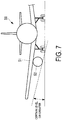
- However, as illustrated in
FIG. 7 , in the case of anaircraft 50 on which anengine 52 is mounted under amain wing 51, clearance from the ground must be secured. Therefore, there is also a limitation on the diameter of the main body of theengine 52. Accordingly, the upper limit of the bypass ratio of turbo fan engines is about 10. - Patent Document 1 below recites one turbo fan engine which generates thrust force and at least one electromagnetic driving fan which generates thrust force being placed on one wing, and that the electromagnetic driving fan is driven by power generated by a power generator provided in the turbo fan engine.
- Patent Document 1: Japanese Unexamined Patent Application Publication No.
2006-205755A - Research is being carried out on an aircraft provided with a turbo fan engine, a power generator that generates power via the rotational force of the turbo fan engine, and a motor driven fan that includes a motor (electric motor) which drives the fan via power supplied from the power generator, wherein both the turbo fan engine and the motor driven fan generate thrust. However, specific research has not been conducted into the placement positions of the turbo fan engine and the motor driven fan.
- For example, in a case where power generated by the power generator is supplied to the motor driven fan and drives the motor driven fan as a thrust force generation device, the supplied power will be high voltage. As such, a power supply line with a large cross-sectional area is preferable, but there is a problem in that such a power supply line would be a heavy object in the aircraft. Additionally, there is a problem in that, depending on the placement position of the power supply line, electromagnetic interference may be generated in the instrumentation of the aircraft. Therefore, the turbo fan engine, the motor driven fan, and the power supply line must be placed appropriately.
- Additionally, specific research has not been conducted into a supporting structure for cases where the turbo fan engine and the motor driven fan are placed on the wing. Furthermore, the amount of air passing through portions other than the core engine of the turbo fan engine increases due to the driving of the motor driven fan. As such, it is possible to increase the bypass ratio of the entire thrust force generation device while maintaining the bypass ratio of the turbo fan engine at a conventional level. However, research has not been conducted into the control of the bypass ratio in accordance with the flight condition of the aircraft.
- In light of these problems, an object of the present invention is to provide a thrust force generation device and an aircraft including the same. The device includes a thrust unit that generates thrust via fuel and a thrust unit that generates thrust via electric power, wherein both of the thrust units are appropriately and efficiently placed.
- A thrust force generation device according to a first aspect of the present invention is provided with a first thrust unit including a generator that generates power via rotational forces of a drive shaft, and that drives a first fan using gas produced by burning fuel; a second thrust unit placed in parallel with the first thrust unit, including a motor driven by power supplied from the generator, and that drives a second fan using the motor; and a conducting unit connecting the generator to the motor, that supplies the power generated by the generator to the motor. In such a thrust force generation device, the first thrust unit and the second thrust unit are integrated with each other; and the conducting unit is placed between the first thrust unit and the second thrust unit.
- According to this configuration, the first thrust unit and the second thrust unit are integrated with each other. As such, in cases where attaching the thrust force generation device to a wing, it is not necessary to transport and install the first thrust unit and the second thrust unit separately, and the units can be handled simultaneously as a single item. Additionally, the first thrust unit and the second thrust unit are placed proximate to each other, and the conducting unit placed between the first thrust unit and the second thrust unit is placed, for example, in a substantially linear manner across a short distance. As a result, compared to a case where spacing between the first thrust unit and the second thrust unit is large, weight of the conducting unit can be reduced, and power loss can be reduced. Furthermore, electromagnetic waves generated when electricity flows through the conducting unit are reduced, and electromagnetic interference that affects instrumentation installed in the aircraft can be suppressed.
- In the first aspect of the invention described above, the first thrust unit and the second thrust unit may be housed in a single housing.
- According to this configuration, the first thrust unit and the second thrust unit can be easily handled as a single item, and the effects of the electromagnetic waves on the outside can be reduced due to the shielding effects of the housing.
- In the first aspect of the invention described above, the thrust force generation device may further include a control unit that adjusts thrust of the first thrust unit and the second thrust unit.
- According to this configuration, the thrust force generated by the first thrust unit and the second thrust unit will each be adjusted, and as such, the proportion that the amount of air, not used in the burning of the fuel in the first thrust unit, occupies can be increased or decreased. As a result, the bypass ratio can be increased or decreased in accordance with, for example, the flight condition, fuel efficiency can be improved, noise can be reduced, and the like.
- In the first aspect of the invention described above, the conducting unit may include a bus bar and a flexible member provided on the bus bar. The flexible member absorbs positional changes of the bus bar.
- According to this configuration, a bus bar is used and, as such, high voltage electricity can be passed through the conducting unit. Additionally, the flexible member is, for example, a spring member or a bearing and absorbs positional changes of the bus bar. As such, damage to the conducting unit can also be avoided when the first thrust unit, the second thrust unit, or the conducting unit is subjected to external forces.
- An aircraft according to a second aspect of the present invention includes the thrust force generation device described above; and a single first supporting part for hanging and supporting the thrust force generation device.
- According to this configuration, the thrust force generation device, in which the first thrust unit and the second thrust unit are integrated, and which is hung and supported by the single first supporting part, is mounted on the aircraft.
- In the second aspect of the invention described above, the aircraft may further include a second supporting part joined to the first thrust unit and a main wing, that bears a tensile load.
- According to this configuration, a moment in the yawing direction is created in the first supporting part described above when the thrust force generated by the first thrust unit is greater than the thrust force generated by the second thrust unit, but deformation of the first supporting part can be suppressed due to the second supporting part bearing the tensile load.
- According to the present invention, in cases where a thrust force generation device includes a thrust unit that generates thrust via fuel and a thrust unit that generates thrust via electric power, both of the thrust units are appropriately and efficiently placed.
-
-
FIG. 1 is a front view illustrating an aircraft on which a thrust force generation device according to an embodiment of the present invention is mounted. -
FIG. 2 is a vertical cross-sectional view illustrating the thrust force generation device according to an embodiment of the present invention. -
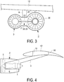
FIG. 3 is a back view illustrating the thrust force generation device according to an embodiment of the present invention. -
FIG. 4 is a vertical cross-sectional view taken along line A-A' inFIG. 2 . -
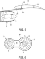
FIG. 5 is a vertical cross-sectional view taken along line B-B' inFIG. 2 . -
FIG. 6 is a vertical cross-sectional view taken along line C-C' inFIG. 2 . -
FIG. 7 is a front view illustrating an aircraft on which a conventional turbo fan engine is mounted. - Hereinafter, a thrust force generation device to be mounted on an aircraft according to an embodiment of the present invention will be described.
- As illustrated in
FIG. 1 , a thrust force generation device 1 is, for example, mounted under amain wing 12 of anaircraft 10, and generates thrust force for propelling theaircraft 10. For example, one thrust force generation device 1 is mounted on one of themain wings 12. The thrust force generation device 1 is mounted as a pair on both of themain wings 12. The thrust force generation device 1 includes a turbofan engine unit 2 and a motor drivenfan unit 3. The turbofan engine unit 2 and the motor drivenfan unit 3 are provided in parallel. - In
FIGS. 1 and2 , the turbofan engine unit 2 is provided on afuselage 11 side of theaircraft 10, and the motor drivenfan unit 3 is provided outward of the turbofan engine unit 2. The thrust force generation device 1 is mounted on both of themain wings 12 so that the turbofan engine units 2 and the motor drivenfan units 3 have left-right symmetry. Note that a configuration is possible in which the placement positions of the turbofan engine unit 2 and the motor drivenfan unit 3 are reversed from that illustrated inFIGS. 1 and2 , and the motor drivenfan unit 3 may be provided on thefuselage 11 side. - Maximum thrust force that can be generated by the thrust force generation device 1 is, for example, from 1 t to 100 t. As illustrated in
FIGS. 3 and 4 , the thrust force generation device 1 is hung from themain wing 12 by, for example, a single pylon (first supporting part) 4. Thepylon 4 has, for example, a structural body such as a truss structure or the like. A first end side of thepylon 4 is connected to substantially a central portion of the thrust force generation device 1, and a second end side is connected to a structural body of the main wing 12 (a rib) (not illustrated), afront spar 13, arear spar 14, or the like. Thepylon 4 can withstand up-down directional, front-back directional, and left-right directional forces to which thepylon 4 is subjected. - The turbo
fan engine unit 2 includes afan 5, acore engine unit 6, a generator 7, and the like. The turbofan engine unit 2 is divided into thecore engine unit 6 provided on an axial line of the drive shaft; and a bypass unit around thecore engine unit 6, through which air that has passed only through thefan 5 flows. Thecore engine unit 6 is constituted from a compressor, a turbine, a combustor, and the like. Thefan 5, the compressor, the turbine, and the generator 7 are provided on the same drive shaft. - The combustor of the
core engine unit 6 combusts fuel and produces high-temperature, high-pressure exhaust gas as a result of the combustion. The high-temperature, high-pressure exhaust gas is jetted from a nozzle, and the jet of this exhaust gas forms a portion of the thrust. Additionally, the exhaust gas produced by the combustion causes the turbine to rotate. Thefan 5 and the compressor are rotatably driven by the rotational force of the turbine. The compressor compresses air taken in through an air intake port of the turbofan engine unit 2, and delivers the compressed air to the compressor. - The
fan 5 is a ducted fan. The air that has passed through thefan 5 is jetted from a fan nozzle and generates thrust. - The generator 7 rotates due to the rotational force of the turbine and generates electric power. The electric power generated by the generator 7 is supplied to the motor driven
fan unit 3 and the like. - The motor driven
fan unit 3 includes afan 8, amotor 9, and the like. Thefan 8 and themotor 9 are provided on the same shaft. - The
motor 9 is rotatably driven by the electric power supplied from the generator 7 of the turbofan engine unit 2. Thefan 8 is rotatably driven by the rotational force of themotor 9. Thefan 8 is a ducted fan. The air that has passed through thefan 8 is jetted from a fan nozzle and generates thrust. - The generator 7 of the turbo
fan engine unit 2 and themotor 9 of the motor drivenfan unit 3 are connected to each other by a conductingunit 20 through which electricity flows, and electric power is supplied from the generator 7 to themotor 9. The conductingunit 20 has a structure and a size capable of withstanding current (e.g. from thousands to tens of thousands of amperes) that flows when the motor drivenfan unit 3 exerts maximum thrust force. - For example, the conducting
unit 20 is constituted from ametal bus bar 21, aflexible member 22, and the like, and thebus bar 21 and theflexible member 22 are connected to each other. A first end side of the conductingunit 20 is connected to the generator 7, and a second end portion is connected to themotor 9. Thebus bar 21 is, for example, a metal plate-like member or rod-like member; and theflexible member 22 is, for example, a net-like member of networked metal wire members, a spring member with elasticity, or the like. - As illustrated in
FIGS. 2 and3 , theflexible member 22 is provided at a middle portion of the conductingunit 20, that is, between two of the bus bars 21. Note that a configuration is possible in which theflexible member 22 is provided between the generator 7 and thebus bar 21, or between themotor 9 and thebus bar 21. By providing theflexible member 22, even when subjected to external forces and the relative positions of the turbofan engine unit 2 and the motor drivenfan unit 3 change, theflexible member 22 will elastically deform and, as a result, disconnections of the conductingunit 20 will not occur and damage to the conductingunit 20 and the like can be avoided. - Note that a configuration is possible in which a bearing is used as the
flexible member 22. The bearing is placed such that the electrical connection of thebus bar 21 is maintained even if the relative positions of the turbofan engine unit 2 and the motor drivenfan unit 3 change. - The conducting
unit 20 is installed in ahousing 30. As a result, the conductingunit 20 is not exposed to the outside and insulation of the conductingunit 20 can be secured. Additionally, by using a shielding material (e.g. a metal plate member or net-like member) on thehousing 30 or on a separate member (not illustrated) covering the conductingunit 20, electromagnetic interference that affects instrumentation installed in theaircraft 10 can be suppressed. - Furthermore, the turbo
fan engine unit 2 and the motor drivenfan unit 3 are placed proximate to each other and, as such, the conductingunit 20 is placed in a substantially linear form across a short distance between the turbofan engine unit 2 and the motor drivenfan unit 3, without having to go around themain wing 12 and the like to be installed. Accordingly, because the length of the conductingunit 20 is short, the weight of the conductingunit 20 can be reduced, which contributes to the reduction of the overall weight of theaircraft 10 and, moreover, power loss can be reduced. Furthermore, electromagnetic waves generated when electricity flows through the conductingunit 20 are reduced, and electromagnetic interference that affects instrumentation installed in theaircraft 10 can be suppressed. - In cases where the turbo
fan engine unit 2 and the motor drivenfan unit 3 are integrated together and the thrust force generation device 1 is attached to themain wing 12, it is not necessary to separately transport and install the turbofan engine unit 2 and the motor drivenfan unit 3, and the units can be handled simultaneously as a single item. For example, the turbofan engine unit 2 and the motor drivenfan unit 3 are housed in thesingle housing 30 surrounding both of the units. Here, the conductingunit 20 is installed in thesame housing 30 in which the turbofan engine unit 2 and the motor drivenfan unit 3 are housed. As a result, the turbofan engine unit 2 and the motor drivenfan unit 3 can be easily handled as a single item, and the effects of the electromagnetic waves on the outside can be reduced due to the shielding effects of thehousing 30. - Note that a partition plate may be provided in the
housing 30 between the turbofan engine unit 2 and the motor drivenfan unit 3. Therefore, fire can be prevented from spreading from the turbofan engine unit 2 to the motor drivenfan unit 3, the strength of the thrust force generation device 1 can be improved, and the like. Thehousing 30 is, for example, constituted by metal plates or carbon fiber reinforced plastic plates. - As illustrated in
FIGS. 2 ,3 , and5 , a strut (second supporting part) 24 is provided between the turbofan engine unit 2 of the thrust force generation device 1 and themain wing 12. Thestrut 24 is parallel to the axial line of the turbofan engine unit 2. A first end side of thestrut 24 is connected to the turbofan engine unit 2, and a second end side of thestrut 24 is connected to a structural body (rib,front spar 13, or the like) of themain wing 12 via a mountingbracket 25. Thestrut 24 is a structural body capable of withstanding the tensile load, and is, for example, a wire member. - In cases where the motor driven
fan unit 3 has stopped and only the turbofan engine unit 2 is being driven, or in cases where the thrust force of the turbofan engine unit 2 is greater than that of the motor drivenfan unit 3, a moment is created in the yawing direction of thepylon 4 due to the turbofan engine unit 2 trying to get out in front of the motor drivenfan unit 3. In such cases, deformation of thepylon 4 is suppressed due to thestrut 24 being provided and bearing the tensile load. - As illustrated in
FIGS. 2 and6 , a thrustforce control device 26 is provided in thehousing 30, and adjusts the thrust of each of the turbofan engine unit 2 and the motor drivenfan unit 3. The thrustforce control device 26 is connected to the generator 7 and themotor 9 and sends and receives control signals to and from the generator 7 or themotor 9 viacontrol wires 27. - The thrust
force control device 26 sets the total thrust of the turbofan engine unit 2 and the motor drivenfan unit 3 to maximum when theaircraft 10 is taking off. On the other hand, when cruising, the thrustforce control device 26 first lowers the thrust force of the turbofan engine unit 2. As a result, when cruising, the amount of air passing through the motor drivenfan unit 3 will be relatively greater than the amount of air passing through the turbofan engine unit 2, and the bypass ratio when cruising will be greater than the bypass ratio when taking off. - With the thrust force generation device 1 according to the present embodiment, air is jetted from the motor driven
fan unit 3 when driving the thrust force generation device 1. As a result, the amount of air not passing through thecore engine unit 6 of the turbofan engine unit 2 increases compared to conventional cases where only a thrust force generation device is mounted. Therefore, as illustrated inFIG. 1 , the bypass ratio can be increased so as to be greater than conventional while securing clearance from the ground. When the bypass ratio is increased, fuel efficiency can be improved and noise can be reduced. Additionally, in cases where it is preferable to achieve a bypass ratio similar to that of a case where only a conventional turbo fan engine is provided, the amount of air not passing through thecore engine unit 6 of the turbofan engine unit 2 can be complemented by the motor drivenfan unit 3. As such, the overall height of the thrust force generation device 1 can be reduced. - The proportion of the thrust of each of the turbo
fan engine unit 2 and the motor drivenfan unit 3 can be appropriately adjusted and, as such, the bypass ratio can be made variable. Accordingly, flight at an optimal bypass ratio, in accordance with the flight condition such as when taking off, when cruising, when landing, or the like, is possible. - With the thrust force generation device 1 according to the present embodiment, the turbo
fan engine unit 2 and the motor drivenfan unit 3 are integrated together. As a result, compared to cases where each of the units is installed separately, the work of installing the thrust force generation device 1 on theaircraft 10 and the structure of theaircraft 10 can be simplified. That is, in cases where installing one thrust force generation device 1 on each of themain wings 12, only thesingle pylon 4 attached to eachmain wing 12 is needed and the work of installation need only be performed at a single location per wing. - Additionally, it is possible to remove the turbo fan engines from existing aircraft on which turbo fan engines are installed, and replace them with the thrust force generation device 1 according to the present embodiment. In this case, the pylon is also required to be replaced, but major changes to the reinforcing structures of the main wings is not necessary.
- Moreover, according to the present embodiment, the
strut 24 is provided between the turbofan engine unit 2 and themain wing 12. As such, the load in the yawing direction to which thepylon 4 is subjected can be reduced. - In consideration of the current that flows when the motor driven
fan unit 3 exerts maximum thrust force and also in consideration of the size and structure of the conductingunit 20, in cases where placing a conducting unit on themain wing 12, there is a possibility of the structure becoming complex or electromagnetic interference being generated in the instrumentation installed in theaircraft 10 due to electromagnetic waves that are generated. However, according to the present embodiment, the turbofan engine unit 2 and the motor drivenfan unit 3 are placed close to each other and the conductingunit 20 is placed in a linear form across a short distance. As a result, a simple structure can be achieved, weight and power loss can be reduced, and the effects of electromagnetic interference can be reduced. Additionally, not only thebus bar 21, but also theflexible member 22 is installed as the conductingunit 20, as such, damage to the conductingunit 20 and the like can be avoided. -
- 1 Thrust force generation device
- 2 Turbo fan engine unit
- 3 Motor driven fan unit
- 4 Pylon (first supporting part)
- 5 Fan (first fan)
- 6 Core engine unit
- 7 Generator
- 8 Fan (second fan)
- 9 Motor
- 10 Aircraft
- 11 Fuselage
- 12 Main wing
- 13 Front spar
- 14 Rear spar
- 20 Conducting unit
- 21 Bus bar
- 22 Flexible member
- 24 Strut (second supporting part)
- 26 Thrust force control device (control device)
- 27 Control wire
- 30 Housing
Claims (6)
- A thrust force generation device, comprising:a first thrust unit including a generator that generates power via rotational forces of a drive shaft, and that drives a first fan using gas produced by burning fuel;a second thrust unit placed in parallel with the first thrust unit, including a motor driven by power supplied from the generator, and that drives a second fan using the motor; anda conducting unit connecting the generator to the motor, that supplies the power generated by the generator to the motor; whereinthe first thrust unit and the second thrust unit are integrated with each other; andthe conducting unit is placed between the first thrust unit and the second thrust unit.
- The thrust force generation device according to claim 1, wherein:the first thrust unit and the second thrust unit are housed in a single housing.
- The thrust force generation device according to claim 1 or 2, further comprising a control unit that adjusts thrust of the first thrust unit and the second thrust unit.
- The thrust force generation device according to any one of claims 1 to 3, wherein:the conducting unit includesa bus bar, anda flexible member provided on the bus bar, that absorbs positional changes of the bus bar.
- An aircraft, comprising:the thrust force generation device according to any one of claims 1 to 4; anda single first supporting part for hanging and supporting the thrust force generation device.
- The aircraft according to claim 5, further comprising a second supporting part joined to the first thrust unit and a main wing, that bears a tensile load.
Applications Claiming Priority (2)
| Application Number | Priority Date | Filing Date | Title |
|---|---|---|---|
| JP2015038282A JP6437347B2 (en) | 2015-02-27 | 2015-02-27 | Thrust generator and aircraft |
| PCT/JP2016/055336 WO2016136770A1 (en) | 2015-02-27 | 2016-02-24 | Thrust force generation device and aircraft |
Publications (3)
| Publication Number | Publication Date |
|---|---|
| EP3243753A1 true EP3243753A1 (en) | 2017-11-15 |
| EP3243753A4 EP3243753A4 (en) | 2017-12-20 |
| EP3243753B1 EP3243753B1 (en) | 2020-07-29 |
Family
ID=56788927
Family Applications (1)
| Application Number | Title | Priority Date | Filing Date |
|---|---|---|---|
| EP16755514.3A Not-in-force EP3243753B1 (en) | 2015-02-27 | 2016-02-24 | Thrust force generation device and aircraft |
Country Status (8)
| Country | Link |
|---|---|
| US (1) | US10752369B2 (en) |
| EP (1) | EP3243753B1 (en) |
| JP (1) | JP6437347B2 (en) |
| CN (1) | CN107249981A (en) |
| BR (1) | BR112017018148A2 (en) |
| CA (1) | CA2977487C (en) |
| RU (1) | RU2662596C1 (en) |
| WO (1) | WO2016136770A1 (en) |
Cited By (3)
| Publication number | Priority date | Publication date | Assignee | Title |
|---|---|---|---|---|
| EP3569856A1 (en) * | 2018-05-14 | 2019-11-20 | Rolls-Royce plc | Electric ducted fan |
| EP3569857A1 (en) * | 2018-05-14 | 2019-11-20 | Rolls-Royce plc | Electric ducted fan |
| GB2544625B (en) * | 2015-10-05 | 2021-09-22 | Safran Aircraft Engines | Aircraft with a propulsion unit with offset fan |
Families Citing this family (23)
| Publication number | Priority date | Publication date | Assignee | Title |
|---|---|---|---|---|
| CN108252807B (en) * | 2016-12-28 | 2019-12-17 | 中国航发商用航空发动机有限责任公司 | Turbo-electric engine propulsion system |
| US10793281B2 (en) * | 2017-02-10 | 2020-10-06 | General Electric Company | Propulsion system for an aircraft |
| US10633104B2 (en) * | 2017-05-17 | 2020-04-28 | General Electric Company | Hybrid-electric propulsion system for an aircraft |
| US10676199B2 (en) | 2017-06-12 | 2020-06-09 | General Electric Company | Propulsion system for an aircraft |
| US11008111B2 (en) * | 2017-06-26 | 2021-05-18 | General Electric Company | Propulsion system for an aircraft |
| GB201811401D0 (en) * | 2018-07-12 | 2018-08-29 | Rolls Royce Plc | Supersonic aircraft propulsion installation |
| US11097849B2 (en) | 2018-09-10 | 2021-08-24 | General Electric Company | Aircraft having an aft engine |
| GB201820919D0 (en) | 2018-12-21 | 2019-02-06 | Rolls Royce Plc | Turbine engine |
| US11204037B2 (en) | 2018-12-21 | 2021-12-21 | Rolls-Royce Plc | Turbine engine |
| GB201820925D0 (en) | 2018-12-21 | 2019-02-06 | Rolls Royce Plc | Turbine engine |
| GB201820924D0 (en) | 2018-12-21 | 2019-02-06 | Rolls Royce Plc | Turbine engine |
| GB201820930D0 (en) * | 2018-12-21 | 2019-02-06 | Rolls Royce Plc | Turbine engine |
| CA3132250A1 (en) * | 2019-03-01 | 2020-09-10 | Andrew D. Smith | Electrical power system for aircraft having hybrid-electric propulsion system |
| EP3931091B1 (en) * | 2019-03-01 | 2025-10-29 | Pratt & Whitney Canada Corp. | Distributed propulsion configurations for aircraft having mixed drive systems |
| EP3931099B1 (en) | 2019-03-01 | 2025-10-29 | Pratt & Whitney Canada Corp. | Cooling system configurations for an aircraft having hybrid-electric propulsion system |
| US11912422B2 (en) * | 2019-08-26 | 2024-02-27 | Hamilton Sundstrand Corporation | Hybrid electric aircraft and powerplant arrangements |
| US20210347490A1 (en) * | 2020-05-07 | 2021-11-11 | Gulfstream Aerospace Corporation | Hybrid jet electric aircraft |
| US11852024B2 (en) | 2020-12-18 | 2023-12-26 | Ge Aviation Systems Llc | Electrical strut for a turbine engine |
| EP4238872A3 (en) * | 2021-02-19 | 2023-11-22 | Lilium eAircraft GmbH | Aircraft engine |
| CN114215658A (en) * | 2021-11-29 | 2022-03-22 | 中国航发沈阳发动机研究所 | Propulsion system with large-range bypass ratio adjusting capacity |
| US11691742B1 (en) | 2022-02-04 | 2023-07-04 | Pratt & Whitney Canada Corp | Containment zone for an electric machine in a hybrid powerplant for an aircraft |
| US20240208663A1 (en) * | 2022-12-23 | 2024-06-27 | Pratt & Whitney Canada Corp. | Hybrid aircraft propulsion system with remotely located electric machine |
| US12291347B2 (en) | 2023-07-31 | 2025-05-06 | Pratt & Whitney Canada Corp. | Containment zone for an electric machine in a hybrid powerplant for an aircraft |
Family Cites Families (36)
| Publication number | Priority date | Publication date | Assignee | Title |
|---|---|---|---|---|
| RU2122965C1 (en) * | 1996-08-12 | 1998-12-10 | Кормилицин Юрий Николаевич | Multi-purpose amphibian |
| CN1200343A (en) * | 1997-05-24 | 1998-12-02 | 王克西 | Passenger plane and fighter aircraft capable of taking-off or landing vertically |
| US6247668B1 (en) * | 1999-07-15 | 2001-06-19 | The Boeing Company | Auxiliary power and thrust unit |
| US10443139B2 (en) * | 2003-09-05 | 2019-10-15 | Brilliant Light Power, Inc. | Electrical power generation systems and methods regarding same |
| JP4092728B2 (en) * | 2005-01-25 | 2008-05-28 | 独立行政法人 宇宙航空研究開発機構 | Aircraft propulsion system |
| JP2008529580A (en) | 2005-02-06 | 2008-08-07 | ウルトラシェイプ エルティーディー. | Non-thermal sonic texture modification |
| WO2006113877A2 (en) * | 2005-04-20 | 2006-10-26 | Lugg Richard H | Hybrid jet/electric vtol aircraft |
| US20090121073A1 (en) | 2006-04-03 | 2009-05-14 | The Boeing Company | Aircraft having a jet engine, an adjustable aft nozzle, and an electric vertical fan |
| FR2902406B1 (en) * | 2006-06-20 | 2008-07-18 | Airbus France Sas | FITTING FOR SUSPENSION MAT FROM A TURBOMOTEUR TO AN AIRCRAFT WING |
| US20080184906A1 (en) * | 2007-02-07 | 2008-08-07 | Kejha Joseph B | Long range hybrid electric airplane |
| US8049460B2 (en) * | 2007-07-18 | 2011-11-01 | Tesla Motors, Inc. | Voltage dividing vehicle heater system and method |
| US8205825B2 (en) * | 2008-02-27 | 2012-06-26 | Spirit Aerosystems, Inc. | Engine pylon made from composite material |
| DE102008011643A1 (en) | 2008-02-28 | 2009-09-03 | Rolls-Royce Deutschland Ltd & Co Kg | Aircraft drive unit with multi-fan design |
| US8291716B2 (en) * | 2008-10-08 | 2012-10-23 | The Invention Science Fund I Llc | Hybrid propulsive engine including at least one independently rotatable turbine stator |
| GB0903423D0 (en) * | 2009-03-02 | 2009-04-08 | Rolls Royce Plc | Variable drive gas turbine engine |
| FR2943039B1 (en) * | 2009-03-12 | 2012-09-28 | Airbus France | PLANE TANK-TAIL AND REVERSE ENGINE. |
| US8294316B2 (en) * | 2009-07-28 | 2012-10-23 | Rolls-Royce North American Technologies, Inc. | Electrical power generation apparatus for contra-rotating open-rotor aircraft propulsion system |
| US20110154805A1 (en) * | 2009-12-31 | 2011-06-30 | Craig Heathco | Power augmentation system for an engine powered air vehicle |
| US20120128493A1 (en) * | 2010-11-19 | 2012-05-24 | Shelley Rudolph Allen | Hybrid free-air gas turbine engine |
| US9212625B2 (en) | 2010-11-19 | 2015-12-15 | Rudolph Allen SHELLEY | Hybrid gas turbine propulsion system |
| US20120209456A1 (en) * | 2011-02-15 | 2012-08-16 | Government Of The United States, As Represented By The Secretary Of The Air Force | Parallel Hybrid-Electric Propulsion Systems for Unmanned Aircraft |
| GB201117692D0 (en) * | 2011-10-13 | 2011-11-23 | Rolls Royce Plc | A distributed propulsion system and method of control |
| JP2013099158A (en) * | 2011-11-02 | 2013-05-20 | Sumitomo Electric Ind Ltd | Connector for inverter device |
| US9637241B2 (en) * | 2012-03-16 | 2017-05-02 | The Boeing Company | Engine mounting system for an aircraft |
| DE102012209803A1 (en) * | 2012-06-12 | 2013-12-12 | Siemens Aktiengesellschaft | Method for providing a predetermined drive characteristic in an aircraft and associated drive device |
| FR2994707B1 (en) * | 2012-08-21 | 2018-04-06 | Snecma | HYBRID TURBOMACHINE WITH CONTRAROTATIVE PROPELLERS |
| US9458766B2 (en) * | 2012-12-24 | 2016-10-04 | United Technologies Corporation | Blind installation pin for a gas turbine engine mount |
| ES2500015B1 (en) * | 2013-02-28 | 2015-06-23 | Axter Aerospace S.L. | Electric auxiliary power system for piston engine aircraft |
| EP2971594B1 (en) * | 2013-03-14 | 2020-01-08 | Rolls-Royce Corporation | Hybrid turbo electric aero-propulsion system control |
| US9404507B2 (en) * | 2013-04-15 | 2016-08-02 | Mra Systems, Inc. | Inner cowl structure for aircraft turbine engine |
| GB2506464B (en) * | 2013-04-24 | 2015-08-19 | Rolls Royce Plc | An Aircraft Powerplant |
| RU2534676C1 (en) * | 2013-05-27 | 2014-12-10 | Дмитрий Сергеевич Дуров | Cryogenic turbo-electric stol aircraft |
| FR3006997B1 (en) * | 2013-06-14 | 2016-12-23 | Airbus | AIRCRAFT WITH ELECTRICAL PROPULSION MEANS |
| US9771863B2 (en) * | 2014-02-07 | 2017-09-26 | United Technologies Corporation | Gas turbine engine with embedded distributed fans |
| ES2644782T3 (en) | 2014-09-17 | 2017-11-30 | Airbus Operations, S.L. | Aircraft hybrid engine |
| US20180002025A1 (en) * | 2016-07-01 | 2018-01-04 | United Technologies Corporation | Aircraft including parallel hybrid gas turbine electric propulsion system |
-
2015
- 2015-02-27 JP JP2015038282A patent/JP6437347B2/en active Active
-
2016
- 2016-02-24 CA CA2977487A patent/CA2977487C/en not_active Expired - Fee Related
- 2016-02-24 WO PCT/JP2016/055336 patent/WO2016136770A1/en not_active Ceased
- 2016-02-24 CN CN201680010192.1A patent/CN107249981A/en active Pending
- 2016-02-24 RU RU2017128641A patent/RU2662596C1/en active
- 2016-02-24 BR BR112017018148-7A patent/BR112017018148A2/en not_active Application Discontinuation
- 2016-02-24 US US15/552,699 patent/US10752369B2/en active Active
- 2016-02-24 EP EP16755514.3A patent/EP3243753B1/en not_active Not-in-force
Cited By (7)
| Publication number | Priority date | Publication date | Assignee | Title |
|---|---|---|---|---|
| GB2544625B (en) * | 2015-10-05 | 2021-09-22 | Safran Aircraft Engines | Aircraft with a propulsion unit with offset fan |
| EP3569856A1 (en) * | 2018-05-14 | 2019-11-20 | Rolls-Royce plc | Electric ducted fan |
| EP3569857A1 (en) * | 2018-05-14 | 2019-11-20 | Rolls-Royce plc | Electric ducted fan |
| CN110486188A (en) * | 2018-05-14 | 2019-11-22 | 劳斯莱斯有限公司 | Electronic ducted fan |
| US11077952B2 (en) | 2018-05-14 | 2021-08-03 | Rolls-Royce Plc | Electric ducted fan |
| US11077953B2 (en) | 2018-05-14 | 2021-08-03 | Rolls-Royce Plc | Electric ducted fan |
| CN110486188B (en) * | 2018-05-14 | 2023-11-10 | 劳斯莱斯有限公司 | Electric conduit fan |
Also Published As
| Publication number | Publication date |
|---|---|
| WO2016136770A1 (en) | 2016-09-01 |
| CN107249981A (en) | 2017-10-13 |
| US10752369B2 (en) | 2020-08-25 |
| JP2016159692A (en) | 2016-09-05 |
| CA2977487A1 (en) | 2016-09-01 |
| US20180044028A1 (en) | 2018-02-15 |
| EP3243753A4 (en) | 2017-12-20 |
| EP3243753B1 (en) | 2020-07-29 |
| BR112017018148A2 (en) | 2018-04-10 |
| CA2977487C (en) | 2019-08-13 |
| RU2662596C1 (en) | 2018-07-26 |
| JP6437347B2 (en) | 2018-12-12 |
Similar Documents
| Publication | Publication Date | Title |
|---|---|---|
| US10752369B2 (en) | Thrust force generation device and aircraft | |
| EP2844556B1 (en) | Hybrid airplane | |
| RU2429168C2 (en) | Aircraft power plant with fan housing support assembly mounted on two separate elements | |
| US8042342B2 (en) | Engine assembly for aircraft comprising an engine as well as a device for locking said engine | |
| US6398161B1 (en) | Device for fixing an aircraft propulsion system to a strut and a strut adapted to said device | |
| US8622342B2 (en) | On-board aircraft auxiliary power systems having dual auxiliary power units | |
| CN100422046C (en) | Suspension rods for jet turbine engines of aircraft | |
| EP2878538A1 (en) | An aircraft | |
| EP3216698A1 (en) | Propulsion system for an aircraft | |
| EP2639159A2 (en) | Engine mounting system for an aircraft | |
| CN102026870A (en) | Engine mounting pylon including means for attaching spars and panels arranged outside the inner space of the box | |
| EP2278203A1 (en) | Integrated electrical cable support | |
| CN105000187B (en) | Component and aircraft for aircraft | |
| CN1993267A (en) | Engine assembly for aircraft | |
| US8907595B2 (en) | Aircraft engine nacelle comprising a mobile cowl moved by electric motors | |
| US9637239B2 (en) | Structure for suspending a turboprop having two unducted propellers on a structural element of an airplane | |
| EP3034395B1 (en) | Aircraft boundary layer removal with auxilliary power unit suction | |
| US20250105609A1 (en) | Systems and methods for routing electrical wiring through an aircraft structure | |
| JP2008545572A (en) | Aircraft engine unit | |
| EP4717607A1 (en) | Ram air turbine fixed within aircraft | |
| EP4474290A1 (en) | Ducted supplemental power unit of aircraft | |
| RU2624488C1 (en) | Manoyan electric plane | |
| RU166774U1 (en) | ELECTRIC PLANE | |
| WO2024102564A4 (en) | Hybrid propulsion system for aircraft | |
| CA2704873A1 (en) | Electrical cable shroud |
Legal Events
| Date | Code | Title | Description |
|---|---|---|---|
| STAA | Information on the status of an ep patent application or granted ep patent |
Free format text: STATUS: THE INTERNATIONAL PUBLICATION HAS BEEN MADE |
|
| PUAI | Public reference made under article 153(3) epc to a published international application that has entered the european phase |
Free format text: ORIGINAL CODE: 0009012 |
|
| STAA | Information on the status of an ep patent application or granted ep patent |
Free format text: STATUS: REQUEST FOR EXAMINATION WAS MADE |
|
| 17P | Request for examination filed |
Effective date: 20170809 |
|
| AK | Designated contracting states |
Kind code of ref document: A1 Designated state(s): AL AT BE BG CH CY CZ DE DK EE ES FI FR GB GR HR HU IE IS IT LI LT LU LV MC MK MT NL NO PL PT RO RS SE SI SK SM TR |
|
| AX | Request for extension of the european patent |
Extension state: BA ME |
|
| A4 | Supplementary search report drawn up and despatched |
Effective date: 20171122 |
|
| RIC1 | Information provided on ipc code assigned before grant |
Ipc: F02C 6/20 20060101ALI20171116BHEP Ipc: B64D 27/02 20060101ALI20171116BHEP Ipc: B64D 27/24 20060101AFI20171116BHEP Ipc: B64D 27/26 20060101ALI20171116BHEP Ipc: B64C 3/32 20060101ALI20171116BHEP |
|
| DAV | Request for validation of the european patent (deleted) | ||
| DAX | Request for extension of the european patent (deleted) | ||
| STAA | Information on the status of an ep patent application or granted ep patent |
Free format text: STATUS: EXAMINATION IS IN PROGRESS |
|
| 17Q | First examination report despatched |
Effective date: 20181023 |
|
| GRAP | Despatch of communication of intention to grant a patent |
Free format text: ORIGINAL CODE: EPIDOSNIGR1 |
|
| STAA | Information on the status of an ep patent application or granted ep patent |
Free format text: STATUS: GRANT OF PATENT IS INTENDED |
|
| INTG | Intention to grant announced |
Effective date: 20200306 |
|
| GRAS | Grant fee paid |
Free format text: ORIGINAL CODE: EPIDOSNIGR3 |
|
| GRAA | (expected) grant |
Free format text: ORIGINAL CODE: 0009210 |
|
| STAA | Information on the status of an ep patent application or granted ep patent |
Free format text: STATUS: THE PATENT HAS BEEN GRANTED |
|
| AK | Designated contracting states |
Kind code of ref document: B1 Designated state(s): AL AT BE BG CH CY CZ DE DK EE ES FI FR GB GR HR HU IE IS IT LI LT LU LV MC MK MT NL NO PL PT RO RS SE SI SK SM TR |
|
| REG | Reference to a national code |
Ref country code: CH Ref legal event code: EP |
|
| REG | Reference to a national code |
Ref country code: AT Ref legal event code: REF Ref document number: 1295500 Country of ref document: AT Kind code of ref document: T Effective date: 20200815 |
|
| REG | Reference to a national code |
Ref country code: IE Ref legal event code: FG4D |
|
| REG | Reference to a national code |
Ref country code: DE Ref legal event code: R096 Ref document number: 602016040857 Country of ref document: DE |
|
| REG | Reference to a national code |
Ref country code: LT Ref legal event code: MG4D |
|
| REG | Reference to a national code |
Ref country code: NL Ref legal event code: MP Effective date: 20200729 |
|
| REG | Reference to a national code |
Ref country code: AT Ref legal event code: MK05 Ref document number: 1295500 Country of ref document: AT Kind code of ref document: T Effective date: 20200729 |
|
| PG25 | Lapsed in a contracting state [announced via postgrant information from national office to epo] |
Ref country code: HR Free format text: LAPSE BECAUSE OF FAILURE TO SUBMIT A TRANSLATION OF THE DESCRIPTION OR TO PAY THE FEE WITHIN THE PRESCRIBED TIME-LIMIT Effective date: 20200729 Ref country code: SE Free format text: LAPSE BECAUSE OF FAILURE TO SUBMIT A TRANSLATION OF THE DESCRIPTION OR TO PAY THE FEE WITHIN THE PRESCRIBED TIME-LIMIT Effective date: 20200729 Ref country code: PT Free format text: LAPSE BECAUSE OF FAILURE TO SUBMIT A TRANSLATION OF THE DESCRIPTION OR TO PAY THE FEE WITHIN THE PRESCRIBED TIME-LIMIT Effective date: 20201130 Ref country code: ES Free format text: LAPSE BECAUSE OF FAILURE TO SUBMIT A TRANSLATION OF THE DESCRIPTION OR TO PAY THE FEE WITHIN THE PRESCRIBED TIME-LIMIT Effective date: 20200729 Ref country code: AT Free format text: LAPSE BECAUSE OF FAILURE TO SUBMIT A TRANSLATION OF THE DESCRIPTION OR TO PAY THE FEE WITHIN THE PRESCRIBED TIME-LIMIT Effective date: 20200729 Ref country code: NO Free format text: LAPSE BECAUSE OF FAILURE TO SUBMIT A TRANSLATION OF THE DESCRIPTION OR TO PAY THE FEE WITHIN THE PRESCRIBED TIME-LIMIT Effective date: 20201029 Ref country code: BG Free format text: LAPSE BECAUSE OF FAILURE TO SUBMIT A TRANSLATION OF THE DESCRIPTION OR TO PAY THE FEE WITHIN THE PRESCRIBED TIME-LIMIT Effective date: 20201029 Ref country code: FI Free format text: LAPSE BECAUSE OF FAILURE TO SUBMIT A TRANSLATION OF THE DESCRIPTION OR TO PAY THE FEE WITHIN THE PRESCRIBED TIME-LIMIT Effective date: 20200729 Ref country code: LT Free format text: LAPSE BECAUSE OF FAILURE TO SUBMIT A TRANSLATION OF THE DESCRIPTION OR TO PAY THE FEE WITHIN THE PRESCRIBED TIME-LIMIT Effective date: 20200729 Ref country code: GR Free format text: LAPSE BECAUSE OF FAILURE TO SUBMIT A TRANSLATION OF THE DESCRIPTION OR TO PAY THE FEE WITHIN THE PRESCRIBED TIME-LIMIT Effective date: 20201030 |
|
| PG25 | Lapsed in a contracting state [announced via postgrant information from national office to epo] |
Ref country code: IS Free format text: LAPSE BECAUSE OF FAILURE TO SUBMIT A TRANSLATION OF THE DESCRIPTION OR TO PAY THE FEE WITHIN THE PRESCRIBED TIME-LIMIT Effective date: 20201129 Ref country code: LV Free format text: LAPSE BECAUSE OF FAILURE TO SUBMIT A TRANSLATION OF THE DESCRIPTION OR TO PAY THE FEE WITHIN THE PRESCRIBED TIME-LIMIT Effective date: 20200729 Ref country code: PL Free format text: LAPSE BECAUSE OF FAILURE TO SUBMIT A TRANSLATION OF THE DESCRIPTION OR TO PAY THE FEE WITHIN THE PRESCRIBED TIME-LIMIT Effective date: 20200729 Ref country code: RS Free format text: LAPSE BECAUSE OF FAILURE TO SUBMIT A TRANSLATION OF THE DESCRIPTION OR TO PAY THE FEE WITHIN THE PRESCRIBED TIME-LIMIT Effective date: 20200729 |
|
| PG25 | Lapsed in a contracting state [announced via postgrant information from national office to epo] |
Ref country code: NL Free format text: LAPSE BECAUSE OF FAILURE TO SUBMIT A TRANSLATION OF THE DESCRIPTION OR TO PAY THE FEE WITHIN THE PRESCRIBED TIME-LIMIT Effective date: 20200729 |
|
| PG25 | Lapsed in a contracting state [announced via postgrant information from national office to epo] |
Ref country code: RO Free format text: LAPSE BECAUSE OF FAILURE TO SUBMIT A TRANSLATION OF THE DESCRIPTION OR TO PAY THE FEE WITHIN THE PRESCRIBED TIME-LIMIT Effective date: 20200729 Ref country code: DK Free format text: LAPSE BECAUSE OF FAILURE TO SUBMIT A TRANSLATION OF THE DESCRIPTION OR TO PAY THE FEE WITHIN THE PRESCRIBED TIME-LIMIT Effective date: 20200729 Ref country code: CZ Free format text: LAPSE BECAUSE OF FAILURE TO SUBMIT A TRANSLATION OF THE DESCRIPTION OR TO PAY THE FEE WITHIN THE PRESCRIBED TIME-LIMIT Effective date: 20200729 Ref country code: SM Free format text: LAPSE BECAUSE OF FAILURE TO SUBMIT A TRANSLATION OF THE DESCRIPTION OR TO PAY THE FEE WITHIN THE PRESCRIBED TIME-LIMIT Effective date: 20200729 Ref country code: EE Free format text: LAPSE BECAUSE OF FAILURE TO SUBMIT A TRANSLATION OF THE DESCRIPTION OR TO PAY THE FEE WITHIN THE PRESCRIBED TIME-LIMIT Effective date: 20200729 Ref country code: IT Free format text: LAPSE BECAUSE OF FAILURE TO SUBMIT A TRANSLATION OF THE DESCRIPTION OR TO PAY THE FEE WITHIN THE PRESCRIBED TIME-LIMIT Effective date: 20200729 |
|
| REG | Reference to a national code |
Ref country code: DE Ref legal event code: R097 Ref document number: 602016040857 Country of ref document: DE |
|
| PG25 | Lapsed in a contracting state [announced via postgrant information from national office to epo] |
Ref country code: AL Free format text: LAPSE BECAUSE OF FAILURE TO SUBMIT A TRANSLATION OF THE DESCRIPTION OR TO PAY THE FEE WITHIN THE PRESCRIBED TIME-LIMIT Effective date: 20200729 |
|
| PLBE | No opposition filed within time limit |
Free format text: ORIGINAL CODE: 0009261 |
|
| STAA | Information on the status of an ep patent application or granted ep patent |
Free format text: STATUS: NO OPPOSITION FILED WITHIN TIME LIMIT |
|
| PG25 | Lapsed in a contracting state [announced via postgrant information from national office to epo] |
Ref country code: SK Free format text: LAPSE BECAUSE OF FAILURE TO SUBMIT A TRANSLATION OF THE DESCRIPTION OR TO PAY THE FEE WITHIN THE PRESCRIBED TIME-LIMIT Effective date: 20200729 |
|
| 26N | No opposition filed |
Effective date: 20210430 |
|
| PG25 | Lapsed in a contracting state [announced via postgrant information from national office to epo] |
Ref country code: SI Free format text: LAPSE BECAUSE OF FAILURE TO SUBMIT A TRANSLATION OF THE DESCRIPTION OR TO PAY THE FEE WITHIN THE PRESCRIBED TIME-LIMIT Effective date: 20200729 |
|
| PG25 | Lapsed in a contracting state [announced via postgrant information from national office to epo] |
Ref country code: MC Free format text: LAPSE BECAUSE OF FAILURE TO SUBMIT A TRANSLATION OF THE DESCRIPTION OR TO PAY THE FEE WITHIN THE PRESCRIBED TIME-LIMIT Effective date: 20200729 |
|
| GBPC | Gb: european patent ceased through non-payment of renewal fee |
Effective date: 20210224 |
|
| REG | Reference to a national code |
Ref country code: BE Ref legal event code: MM Effective date: 20210228 |
|
| PG25 | Lapsed in a contracting state [announced via postgrant information from national office to epo] |
Ref country code: CH Free format text: LAPSE BECAUSE OF NON-PAYMENT OF DUE FEES Effective date: 20210228 Ref country code: LU Free format text: LAPSE BECAUSE OF NON-PAYMENT OF DUE FEES Effective date: 20210224 Ref country code: LI Free format text: LAPSE BECAUSE OF NON-PAYMENT OF DUE FEES Effective date: 20210228 |
|
| PG25 | Lapsed in a contracting state [announced via postgrant information from national office to epo] |
Ref country code: GB Free format text: LAPSE BECAUSE OF NON-PAYMENT OF DUE FEES Effective date: 20210224 Ref country code: IE Free format text: LAPSE BECAUSE OF NON-PAYMENT OF DUE FEES Effective date: 20210224 |
|
| PGFP | Annual fee paid to national office [announced via postgrant information from national office to epo] |
Ref country code: DE Payment date: 20211230 Year of fee payment: 7 |
|
| PG25 | Lapsed in a contracting state [announced via postgrant information from national office to epo] |
Ref country code: BE Free format text: LAPSE BECAUSE OF NON-PAYMENT OF DUE FEES Effective date: 20210228 |
|
| PG25 | Lapsed in a contracting state [announced via postgrant information from national office to epo] |
Ref country code: HU Free format text: LAPSE BECAUSE OF FAILURE TO SUBMIT A TRANSLATION OF THE DESCRIPTION OR TO PAY THE FEE WITHIN THE PRESCRIBED TIME-LIMIT; INVALID AB INITIO Effective date: 20160224 |
|
| PG25 | Lapsed in a contracting state [announced via postgrant information from national office to epo] |
Ref country code: CY Free format text: LAPSE BECAUSE OF FAILURE TO SUBMIT A TRANSLATION OF THE DESCRIPTION OR TO PAY THE FEE WITHIN THE PRESCRIBED TIME-LIMIT Effective date: 20200729 |
|
| REG | Reference to a national code |
Ref country code: DE Ref legal event code: R119 Ref document number: 602016040857 Country of ref document: DE |
|
| PG25 | Lapsed in a contracting state [announced via postgrant information from national office to epo] |
Ref country code: DE Free format text: LAPSE BECAUSE OF NON-PAYMENT OF DUE FEES Effective date: 20230901 |
|
| PG25 | Lapsed in a contracting state [announced via postgrant information from national office to epo] |
Ref country code: MK Free format text: LAPSE BECAUSE OF FAILURE TO SUBMIT A TRANSLATION OF THE DESCRIPTION OR TO PAY THE FEE WITHIN THE PRESCRIBED TIME-LIMIT Effective date: 20200729 |
|
| PG25 | Lapsed in a contracting state [announced via postgrant information from national office to epo] |
Ref country code: TR Free format text: LAPSE BECAUSE OF FAILURE TO SUBMIT A TRANSLATION OF THE DESCRIPTION OR TO PAY THE FEE WITHIN THE PRESCRIBED TIME-LIMIT Effective date: 20200729 |
|
| PG25 | Lapsed in a contracting state [announced via postgrant information from national office to epo] |
Ref country code: MT Free format text: LAPSE BECAUSE OF FAILURE TO SUBMIT A TRANSLATION OF THE DESCRIPTION OR TO PAY THE FEE WITHIN THE PRESCRIBED TIME-LIMIT Effective date: 20200729 |
|
| PG25 | Lapsed in a contracting state [announced via postgrant information from national office to epo] |
Ref country code: FR Free format text: LAPSE BECAUSE OF NON-PAYMENT OF DUE FEES Effective date: 20240229 |
|
| PG25 | Lapsed in a contracting state [announced via postgrant information from national office to epo] |
Ref country code: FR Free format text: LAPSE BECAUSE OF NON-PAYMENT OF DUE FEES Effective date: 20240229 |
|
| PGFP | Annual fee paid to national office [announced via postgrant information from national office to epo] |
Ref country code: FR Payment date: 20230110 Year of fee payment: 8 |