EP3243697A1 - Reinforced ergonomic seat for racing vehicles, particularly for karts - Google Patents
Reinforced ergonomic seat for racing vehicles, particularly for karts Download PDFInfo
- Publication number
- EP3243697A1 EP3243697A1 EP17170904.1A EP17170904A EP3243697A1 EP 3243697 A1 EP3243697 A1 EP 3243697A1 EP 17170904 A EP17170904 A EP 17170904A EP 3243697 A1 EP3243697 A1 EP 3243697A1
- Authority
- EP
- European Patent Office
- Prior art keywords
- seat
- driver
- seatback
- constituted
- reinforcing
- Prior art date
- Legal status (The legal status is an assumption and is not a legal conclusion. Google has not performed a legal analysis and makes no representation as to the accuracy of the status listed.)
- Withdrawn
Links
- 230000003014 reinforcing effect Effects 0.000 claims abstract description 30
- 239000011152 fibreglass Substances 0.000 claims abstract description 10
- 210000000689 upper leg Anatomy 0.000 claims abstract description 7
- 230000001133 acceleration Effects 0.000 claims abstract description 6
- 239000000463 material Substances 0.000 claims abstract description 6
- 229920000049 Carbon (fiber) Polymers 0.000 claims abstract description 5
- 239000004760 aramid Substances 0.000 claims abstract description 5
- 239000004917 carbon fiber Substances 0.000 claims abstract description 5
- 210000002414 leg Anatomy 0.000 claims abstract description 5
- 239000012783 reinforcing fiber Substances 0.000 claims abstract description 3
- 230000002093 peripheral effect Effects 0.000 claims description 8
- 238000005299 abrasion Methods 0.000 claims description 4
- 229920003235 aromatic polyamide Polymers 0.000 claims description 4
- 229920002994 synthetic fiber Polymers 0.000 claims description 4
- 239000012209 synthetic fiber Substances 0.000 claims description 4
- 244000025254 Cannabis sativa Species 0.000 claims description 2
- 235000012766 Cannabis sativa ssp. sativa var. sativa Nutrition 0.000 claims description 2
- 235000012765 Cannabis sativa ssp. sativa var. spontanea Nutrition 0.000 claims description 2
- OKTJSMMVPCPJKN-UHFFFAOYSA-N Carbon Chemical compound [C] OKTJSMMVPCPJKN-UHFFFAOYSA-N 0.000 claims description 2
- 229920000742 Cotton Polymers 0.000 claims description 2
- 235000009120 camo Nutrition 0.000 claims description 2
- 229910052799 carbon Inorganic materials 0.000 claims description 2
- 235000005607 chanvre indien Nutrition 0.000 claims description 2
- 239000002131 composite material Substances 0.000 claims description 2
- 239000000835 fiber Substances 0.000 claims description 2
- 239000011521 glass Substances 0.000 claims description 2
- 239000011487 hemp Substances 0.000 claims description 2
- 230000003116 impacting effect Effects 0.000 claims description 2
- 238000005452 bending Methods 0.000 claims 1
- 229920006231 aramid fiber Polymers 0.000 abstract description 3
- VNWKTOKETHGBQD-UHFFFAOYSA-N methane Chemical compound C VNWKTOKETHGBQD-UHFFFAOYSA-N 0.000 description 3
- 230000003313 weakening effect Effects 0.000 description 3
- 239000010426 asphalt Substances 0.000 description 1
- 239000000725 suspension Substances 0.000 description 1
Images




Classifications
-
- B—PERFORMING OPERATIONS; TRANSPORTING
- B60—VEHICLES IN GENERAL
- B60N—SEATS SPECIALLY ADAPTED FOR VEHICLES; VEHICLE PASSENGER ACCOMMODATION NOT OTHERWISE PROVIDED FOR
- B60N2/00—Seats specially adapted for vehicles; Arrangement or mounting of seats in vehicles
- B60N2/68—Seat frames
- B60N2/686—Panel like structures
-
- B—PERFORMING OPERATIONS; TRANSPORTING
- B60—VEHICLES IN GENERAL
- B60N—SEATS SPECIALLY ADAPTED FOR VEHICLES; VEHICLE PASSENGER ACCOMMODATION NOT OTHERWISE PROVIDED FOR
- B60N2/00—Seats specially adapted for vehicles; Arrangement or mounting of seats in vehicles
- B60N2/70—Upholstery springs ; Upholstery
- B60N2/7017—Upholstery springs ; Upholstery characterised by the manufacturing process; manufacturing upholstery or upholstery springs not otherwise provided for
Definitions
- the invention relates to a reinforced ergonomic seat for racing vehicles, particularly for karts, adapted to improve the wrapping and the comfort of the driver and consequently the safety and the drive performances.
- seats adapted to be fixed through brackets and fastenings to the frame of the kart, which are realized integral solely with fiberglass and shaped with a shell shape, in particular with a slightly curved seatback joined to a flat seat that is extended frontally with two little side portions adapted to support the thighs of the driver, furthermore, the seat is provided with two flanks, which join the seatback and the seat, slightly curved inward the same seat and with an almost triangular side profile.
- the object of the present invention is to realize a reinforced ergonomic seat for racing vehicles, in particular for karts, that eliminate the above said problems of safety and comfort for the driver.
- This reinforced ergonomic seat is realized with the constructive characteristics that will be described, given by way of a not limitative example only and with particular reference to the accompanying claims and drawings, in which :
- the present invention relates to a reinforced ergonomic seat for racing vehicles, particularly for karts, adapted to house a driver in such a way as to increase the safety and the drive comfort, and particularly for absorbing the forces generated during the guide in the phases of acceleration, of deceleration, and during the curves and for limiting the wear and the possibility of breaking of the same seat due to the mechanical stresses in to the fixing points to the frame of the vehicle and to the impacts with the ground.
- the reinforced ergonomic seat 10, object of the present invention is made with a shaped shell shape with a plurality of layers of different materials overlapped to each other, which materials are constituted by at least two lower layers of fiberglass, by a plurality of intermediate reinforcing elements overlapped to said first lower layers, and each one constituted by a layer of reinforcing fibers, preferably aramid synthetic fiber and/or carbon fiber, and by at least two upper layers overlapped to said intermediate reinforcing layers and constituted by fiberglass.
- Said seat 10 comprises a seatback 11 inclined rearwards from the bottom to the top with a concave curvature, and which seatback 11 is joined at its lower part to the zone of the seat 12, which comprises a first lower flat part 13, which is extended frontally in a second front part 14 positioned at a higher level, initially with a lower convex curved profile 15 that is joined with a flat profile 16, which ends finally frontwards with two horizontal side projected portions 17 joined to each other.
- the seatback 11 together with the seat 12 are laterally closed by two side vertical flanks 18 and 19, which have an upper profile 20 shaped as it will be described.
- Said upper profile 20 joins the upper edge 21 of the seatback 11 to the front edge 21' of said side portions 17, and has a first horizontal part 22, that continues approximately up to the vertical of the back part of the seat 12, a second part inclined frontally 23, that continues downward approximately up to the middle of the seatback 11 and the middle of the seat 12, a third part curved concave upward 24, with the lowest point that remains in an upper position with respect to the horizontal side portions 17 and that continues approximately up to the middle of the curved profile 15 of the part 14 of the seat 12, a fourth part almost horizontal 25 joined to a fifth and last part 26 inclined frontally that continues downward up to reach the front edge of the respective side part 17.
- the side vertical flanks 18 and 19 create each one a first containing and protecting back area 27 for the driver's bust, which is slightly re-entering inward the seat 10, in correspondence of the first two parts 22 and 23 of the same profile 20, furthermore each one of them creates a second containing and protecting central area 28 for the driver's hips, in correspondence of the third part 24 of the of the profile 20, and finally each one of them creates a third containing and protecting front area 29 for the driver's thighs, so that the same driver has a correct driving position as far as the bust is concerned and also he has the legs supported according to the natural driving position of a kart, in which they find themselves in the bent position.
- the seat 10 having advantageously these flanks 18 and 19 very raised, offers an excellent protection to the driver's body, contrary to the seats used at the present time.
- the upper peripheral edge 30 of the seat 10 has an external curvature downward, in such a way as to increase the mechanical strength thereof
- the third concave upward part 24 of the profile 20 has a function of weakening the flanks 18 and 19 by making an upper recess 24', in such a way that their back part 27 and their front part 29 be advantageously not constrained to each other, contrary to the seats used at the present time, by allowing the seat 10 to perform some side flexions and torsions when the forces are applied during the driving phase, in particular during the acceleration and deceleration phases and along the curves, so that the same seat 10 may absorb these forces by deforming itself and by following the side movements of the driver, thereby increasing the comfort and the performances of the drive.
- a plurality of said intermediate reinforcing elements 31 is included into the seat 10, which elements are each constituted by a layer of synthetic aramid fiber and/or carbon fiber, and are adapted to stiff and to reinforce the most stressed areas of the same seat 10 in which they are included, in the ways and for the aims that will be described.
- a first reinforcing element 32 is made with an horizontal central band 33, the end portions of which 34, 35 are extended downward with a parallelepiped shape, and such first element 32 is included into the seat 10 in such a way that the central band 33 be arranged in the upper part of the seatback 11 and follows the profile of its upper edge 21, and in such a way that the two end portions 34, 35 be arranged in the upper area of the back parts 27 of the flanks 18, 19 and follow the profile thereof.
- a second reinforcing element 37 is included into the seat area 12, and follows the shape and the surface thereof, and may be provided with a plurality of emptied weakening areas 38 positioned longitudinally in the interior thereof.
- a third and a fourth reinforcing elements 39, 40, mirror-like shaped are arranged respectively in correspondence of said side portions 17 by extending toward the lower part 14 approximately up to its middle and by extending also vertically partially into the front parts 29 of the flanks 18, 19.
- Said third and fourth elements 39, 40 may be provided with internal emptied weakening areas 41.
- the above said reinforcing elements 32, 37, 39, 40 are arranged in to the areas submitted to high mechanical stresses, such as for example the areas for fixing to the kart frame and/or the areas impacting the ground, in such a way that it is reduced the risk of breaking of the same seat caused by the greater stress due to the fixing means (not shown) inserted therein, such as for example screws, rivets, brackets, etc.., contrary to the seats used at the present time, which are secured to the frame directly on to the weaker fiberglass.
- the second reinforcing element 37 furthermore, included into the seat area 12, being situated at a little distance from the ground, often comes into contact therewith, and therefore is subjected to a strong abrasion, so that by using carbon fiber or better synthetic aramid fiber, it becomes more resistant to the impacts and the abrasions, and therefore it is advantageously more durable and safe than the classic seats realized of fiberglass only. Furthermore, by obtaining a stiff seat 12 with the addition of the reinforcing element 37, the driver doesn't deform it with its weight, and consequently it is obtained a driving with more comfort and more safe.
- the reinforcing elements 39 and 40 by stiffening the seat in correspondence of the side portions 17, allows that the driver's thighs be always good supported in their lower part by maintaining them bent, and by increasing the driving comfort and safety.
- Said seat 10 in a second embodiment thereof, as visible in the Figs. 7 and 8 , in addition to all the above described characteristics, has, into the lower hollow area 42 of the peripheral edge 30 obtained with its external curvature downward, at least a reinforcing lengthened element 43 that is partially included into said layers of materials overlapped to each other, and is adapted to increase the resistance to the transversal and/or longitudinal deformation of the same seat 10 for its entirety, or for some parts thereof only.
- Such reinforcing element 43 is constituted by a rope 43 of the twisted type, realized with a plurality of strands made of natural fibers, such as for example cotton, linen, hemp, and/or synthetic fibers, such as for example of glass, of aramid, of carbon, and twisted onto themselves, and which therefore have a reduced weight and the capability to absorb the composite material into which they are included, thereby creating a reinforced shell seat 10 that be resistant to the longitudinal and transversal deformations and that has advantageously an integral body.
- natural fibers such as for example cotton, linen, hemp, and/or synthetic fibers, such as for example of glass, of aramid, of carbon, and twisted onto themselves, and which therefore have a reduced weight and the capability to absorb the composite material into which they are included, thereby creating a reinforced shell seat 10 that be resistant to the longitudinal and transversal deformations and that has advantageously an integral body.
- the seat may have an unique lengthened element 43 along the entire cavity 42 of the peripheral edge 30, or one lengthened element 43 arranged into a limited section of the cavity 42, or a plurality of lengthened elements 43 arranged in different sections of the cavity 42.
Landscapes
- Engineering & Computer Science (AREA)
- Aviation & Aerospace Engineering (AREA)
- Transportation (AREA)
- Mechanical Engineering (AREA)
- Manufacturing & Machinery (AREA)
- Seats For Vehicles (AREA)
Abstract
Description
- The invention relates to a reinforced ergonomic seat for racing vehicles, particularly for karts, adapted to improve the wrapping and the comfort of the driver and consequently the safety and the drive performances.
- At the present time, there are known seats, adapted to be fixed through brackets and fastenings to the frame of the kart, which are realized integral solely with fiberglass and shaped with a shell shape, in particular with a slightly curved seatback joined to a flat seat that is extended frontally with two little side portions adapted to support the thighs of the driver, furthermore, the seat is provided with two flanks, which join the seatback and the seat, slightly curved inward the same seat and with an almost triangular side profile.
- These seats are very tiring for the driver, since the legs for being well supported by the seat, onto which the driver is seated, must be practically stretched, whereas during the kart driving, for the size of this latter, the legs must work in a flexed position.
- An additional problem deriving by the fact that the karts are not provided of suspensions and that the above said seats are stiff, is that in the curve phase or in the acceleration phase during the driving of the same kart, there aren't provided some means adapted to absorb the forces being generated, such as for example the centrifugal force, and the seats, being almost non-deformable, cannot adapt themselves to the shape of the driver's back that is so subjected to the above said forces, therefore these seats are less ergonomic and tire the driver's back thereby reducing the driving safety.
- Another problem derived by the use of the above said seats, made of fiberglass only, is the fact that the lower part of their seat is free and positioned to a very low level, therefore during the driving phase the seat often comes into contact with the ground, which is constituted by asphalt or by kerbs made of concrete, and therefore it is subjected to the abrasion and impacts, that may cause breakings of the same seat and therefore to become dangerous for the driver.
- The object of the present invention is to realize a reinforced ergonomic seat for racing vehicles, in particular for karts, that eliminate the above said problems of safety and comfort for the driver. This reinforced ergonomic seat is realized with the constructive characteristics that will be described, given by way of a not limitative example only and with particular reference to the accompanying claims and drawings, in which :
-
Fig. 1 shows a perspective side view from the top of the reinforced ergonomic seat, according to the invention ; -
Fig. 2 shows a perspective side view of the seat ofFig. 1 ; -
Fig. 3 shows a perspective front view from the top of the seat ofFig. 1 ; -
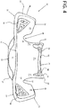
Fig. 4 shows a perspective front view of the seat ofFig. 1 ; -
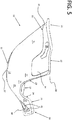
Fig. 5 shows a perspective side and back view of the seat ofFig. 1 ; -
Fig. 6 shows a perspective back view of the seat ofFig. 1 ; -
Fig. 7 shows a perspective front view of the reinforced ergonomic seat, in a second embodiment thereof, according to the invention ; -
Fig. 8 shows an enlarged item of the seat ofFig. 7 . - The present invention relates to a reinforced ergonomic seat for racing vehicles, particularly for karts, adapted to house a driver in such a way as to increase the safety and the drive comfort, and particularly for absorbing the forces generated during the guide in the phases of acceleration, of deceleration, and during the curves and for limiting the wear and the possibility of breaking of the same seat due to the mechanical stresses in to the fixing points to the frame of the vehicle and to the impacts with the ground.
- The reinforced
ergonomic seat 10, object of the present invention, is made with a shaped shell shape with a plurality of layers of different materials overlapped to each other, which materials are constituted by at least two lower layers of fiberglass, by a plurality of intermediate reinforcing elements overlapped to said first lower layers, and each one constituted by a layer of reinforcing fibers, preferably aramid synthetic fiber and/or carbon fiber, and by at least two upper layers overlapped to said intermediate reinforcing layers and constituted by fiberglass. - Said
seat 10 comprises aseatback 11 inclined rearwards from the bottom to the top with a concave curvature, and whichseatback 11 is joined at its lower part to the zone of theseat 12, which comprises a first lowerflat part 13, which is extended frontally in asecond front part 14 positioned at a higher level, initially with a lower convexcurved profile 15 that is joined with aflat profile 16, which ends finally frontwards with two horizontal side projectedportions 17 joined to each other. Theseatback 11 together with theseat 12 are laterally closed by two sidevertical flanks upper profile 20 shaped as it will be described. - Said
upper profile 20 joins theupper edge 21 of theseatback 11 to the front edge 21' of saidside portions 17, and has a firsthorizontal part 22, that continues approximately up to the vertical of the back part of theseat 12, a second part inclined frontally 23, that continues downward approximately up to the middle of theseatback 11 and the middle of theseat 12, a third part curved concave upward 24, with the lowest point that remains in an upper position with respect to thehorizontal side portions 17 and that continues approximately up to the middle of thecurved profile 15 of thepart 14 of theseat 12, a fourth part almost horizontal 25 joined to a fifth andlast part 26 inclined frontally that continues downward up to reach the front edge of therespective side part 17. - With this
shaped profile 20, the sidevertical flanks back area 27 for the driver's bust, which is slightly re-entering inward theseat 10, in correspondence of the first twoparts same profile 20, furthermore each one of them creates a second containing and protectingcentral area 28 for the driver's hips, in correspondence of thethird part 24 of the of theprofile 20, and finally each one of them creates a third containing and protectingfront area 29 for the driver's thighs, so that the same driver has a correct driving position as far as the bust is concerned and also he has the legs supported according to the natural driving position of a kart, in which they find themselves in the bent position. - The
seat 10, having advantageously theseflanks - Finally, the upper
peripheral edge 30 of theseat 10 has an external curvature downward, in such a way as to increase the mechanical strength thereof - The third concave upward
part 24 of theprofile 20 has a function of weakening theflanks back part 27 and theirfront part 29 be advantageously not constrained to each other, contrary to the seats used at the present time, by allowing theseat 10 to perform some side flexions and torsions when the forces are applied during the driving phase, in particular during the acceleration and deceleration phases and along the curves, so that thesame seat 10 may absorb these forces by deforming itself and by following the side movements of the driver, thereby increasing the comfort and the performances of the drive. - As initially specified, a plurality of said
intermediate reinforcing elements 31 is included into theseat 10, which elements are each constituted by a layer of synthetic aramid fiber and/or carbon fiber, and are adapted to stiff and to reinforce the most stressed areas of thesame seat 10 in which they are included, in the ways and for the aims that will be described. - A first reinforcing
element 32 is made with an horizontalcentral band 33, the end portions of which 34, 35 are extended downward with a parallelepiped shape, and suchfirst element 32 is included into theseat 10 in such a way that thecentral band 33 be arranged in the upper part of theseatback 11 and follows the profile of itsupper edge 21, and in such a way that the twoend portions back parts 27 of theflanks element 32, it is possible to create some internalempty areas 36, such as for example in the joining area between the horizontal band and its twoend portions - A second reinforcing
element 37 is included into theseat area 12, and follows the shape and the surface thereof, and may be provided with a plurality of emptied weakeningareas 38 positioned longitudinally in the interior thereof. - A third and a fourth reinforcing
elements side portions 17 by extending toward thelower part 14 approximately up to its middle and by extending also vertically partially into thefront parts 29 of theflanks fourth elements areas 41. The above said reinforcingelements - The second reinforcing
element 37, furthermore, included into theseat area 12, being situated at a little distance from the ground, often comes into contact therewith, and therefore is subjected to a strong abrasion, so that by using carbon fiber or better synthetic aramid fiber, it becomes more resistant to the impacts and the abrasions, and therefore it is advantageously more durable and safe than the classic seats realized of fiberglass only. Furthermore, by obtaining astiff seat 12 with the addition of the reinforcingelement 37, the driver doesn't deform it with its weight, and consequently it is obtained a driving with more comfort and more safe. - Finally, the reinforcing
elements side portions 17, allows that the driver's thighs be always good supported in their lower part by maintaining them bent, and by increasing the driving comfort and safety. - With this above described solution therefore it is obtained a seat for kart that is always lightweight, and more ergonomic, durable and safe than the seats used at the present time.
- Said
seat 10, in a second embodiment thereof, as visible in theFigs. 7 and8 , in addition to all the above described characteristics, has, into the lowerhollow area 42 of theperipheral edge 30 obtained with its external curvature downward, at least a reinforcing lengthenedelement 43 that is partially included into said layers of materials overlapped to each other, and is adapted to increase the resistance to the transversal and/or longitudinal deformation of thesame seat 10 for its entirety, or for some parts thereof only. - Such reinforcing
element 43 is constituted by arope 43 of the twisted type, realized with a plurality of strands made of natural fibers, such as for example cotton, linen, hemp, and/or synthetic fibers, such as for example of glass, of aramid, of carbon, and twisted onto themselves, and which therefore have a reduced weight and the capability to absorb the composite material into which they are included, thereby creating a reinforcedshell seat 10 that be resistant to the longitudinal and transversal deformations and that has advantageously an integral body. - Depending on the area of the
seat 10 intended to be stiffed, the seat may have an unique lengthenedelement 43 along theentire cavity 42 of theperipheral edge 30, or one lengthenedelement 43 arranged into a limited section of thecavity 42, or a plurality of lengthenedelements 43 arranged in different sections of thecavity 42.
Claims (13)
- Reinforced ergonomic seat (10) for racing vehicles, particularly for karts, adapted to house a driver in such a way as to increase the safety and the drive comfort, and particularly to absorb the forces generated during the guide in the phases of acceleration, of deceleration, and during the curves and for limiting the wear and the possibility of breaking of the same seat due to the mechanical stresses in to the fixing points to the frame of the vehicle and due to the impacts with the ground, said seat (10) being realized with a shaped shell form constituted by a seatback (11) joined to a seat (12), both closed laterally by two vertical side flanks (18, 19), characterized in that said seat (10) is made with a plurality of layers of different materials overlapped to each other, constituted by at least two lower layers of fiberglass, by a plurality of intermediate reinforcing elements (31) overlapped to said first lower layers, and each constituted by a layer of reinforcing fibers, preferably aramid synthetic fibers and/or carbon fibers, and by at least two upper layers overlapped to said intermediate reinforcing layers (31) and constituted by fiberglass, said seatback (11) being inclined in the rear part from the bottom to the top with a concave curvature, and being joined at its lower part to the zone of the seat (12), comprising a first lower flat part (13) and a second front part (14) which is extended in front of said first flat part (13) with an inclination directed upward, said second front part (14) being linked in the front thereof with two horizontal side projected portions (17) linked to each other, for ensuring to the driver a correct driving position and the support of the legs of the same one, said seatback (11), said seat (12) and two side vertical flanks (18, 19) being shaped for containing and protecting the body and the thighs of the driver and for ensuring a side flexion and torsion of the so built seat (10), during all the distance covered by the kart onto which it is assembled.
- Seat according to claim 1, characterized in that said flanks (18, 19) have an upper profile (20), with which each of them create in correspondence of the seatback (11) a first containing and protecting back area (27) for the driver's chest, in correspondence of the flat area (13) of the seat (12) a second containing and protecting central area (28) for the driver's hips, and in correspondence of the part (14) of the seat (12) a third containing and protecting front area (29) for the driver's thighs, said second central part (28) having an upper recess (24') with a profile concave upward (24) adapted to weaken the flanks (18 and 19), in such a way that their back part (27) and their front part (29) be not constrained to each other, by allowing the seat (10) to perform some side flexions and torsions required by the forces during the driving phase, such as for example during the acceleration and deceleration phases and during the curves, so that the same seat (10) may absorb these forces by deforming itself and following the side movements of the driver.
- Seat according to claim 2, characterized in that said upper profile (20) joins the upper edge (21) of the seatback (11) to the front edge (21') of said side portions (17), and has a first horizontal part (22), that continues approximately up to the vertical of the back part of the seat (12), a second part inclined frontally (23), that continues downward approximately up to the middle of the seatback (11) and the middle of the seat (12), a third part constituted by the curved area concave upward (24), with the lowest point that remains in an upper position with respect to the horizontal side portions (17) and that continues approximately up to the middle of the curved profile (15) of the part (14) of the seat (12), a fourth part almost horizontal (25) joined to a fifth and last part (26) inclined frontally that continues downward up to reach the front edge of the respective side part (17).
- Seat according to claim 1, characterized in that said intermediate reinforcing elements (31) are constituted by a first reinforcing element (32), by a second reinforcing element (37), and by a third and a fourth reinforcing elements (39, 40) equal and mirror-like to each other, said first, second, third and fourth reinforcing elements (32 ; 37 ; 39, 40) being arranged in to the areas of the seat (10) submitted to high mechanical stresses, such as for example the areas for fixing to the kart frame and/or the areas impacting the ground.
- Seat according to claim 4, characterized in that said first reinforcing element (32) is positioned partially into the upper part of the seatback (11) and partially into the upper area of the back parts (27) of the flanks (18, 19) and follows the profile thereof.
- Seat according to claim 5, characterized in that said first intermediate reinforcing element (32) is made with an horizontal central band (33) the end portions of which (34, 35) are extended downward with a parallelepiped shape, and such first element (32) is included into the seat (10) in such a way that the central band (33) be arranged in the upper part of the seatback (11) and follows the profile of its upper edge (21), and in such a way that the two end portions (34, 35) be arranged in the upper area of the back parts (27) of the flanks (18, 19) and follow the profile thereof.
- Seat according to claim 4, characterized in that said second reinforcing element (37) is included into the seat area (12), by following the shape and the surface thereof, and is adapted to make the seat (12) more resistant to the abrasions and impacts caused by the contact with the ground.
- Seat according to claim 4, characterized in that said third and fourth reinforcing elements (39 and 40) are arranged respectively in correspondence of said side portions (17) by extending it toward the lower part (14) approximately up to its middle and by extending it also vertically partially into the front parts (29) of the flanks (18, 19), said reinforcing elements (39 and 40) being adapted to stiffen the seat in correspondence of the side portions (17) in such a way that the driver's thighs be always good supported in their lower part by maintaining them bent, and by increasing the driving comfort and safety.
- Seat according to claim 2, characterized in that said upper peripheral edge (30) of the seat (10) has an external curved bending directed downward, in such a way as to increase the mechanical strength thereof.
- Seat according to claim 9, characterized in that said peripheral edge (30), with its external curvature downward, creates a lower hollow area (42), wherein at least a reinforcing lengthened element (43) is partially included into said layers of materials overlapped to each other, said reinforcing lengthened element (43) being adapted to increase the resistance to the transversal and/or longitudinal deformation of the same seat (10) for its entirety, or for some parts thereof only, such reinforcing element (43) being constituted by a rope (43) of the twisted type, realized with a plurality of strands made of natural fibers, such as for example cotton, linen, hemp, and/or synthetic fibers, such as for example of glass, of aramid, of carbon, and twisted onto themselves, and that therefore have a reduced weight and the capability to absorb the composite material into which they are included.
- Seat according to claim 10, characterized in that said seat (10) has a unique lengthened element (43) along the entire cavity (42) of the peripheral edge (30).
- Seat according to claim 10, characterized in that said seat (10) has a sole lengthened element (43) arranged into a limited section of the cavity (42) of the peripheral edge (30).
- Seat according to claim 10, characterized in that said seat (10) has a plurality of lengthened elements (43) arranged in different limited sections of the cavity (42) of the peripheral edge (30).
Applications Claiming Priority (1)
| Application Number | Priority Date | Filing Date | Title |
|---|---|---|---|
| ITUA2016A003387A ITUA20163387A1 (en) | 2016-05-12 | 2016-05-12 | ERGONOMIC REINFORCED SEAT FOR COMPETITION VEHICLES, IN PARTICULAR FOR KART |
Publications (1)
| Publication Number | Publication Date |
|---|---|
| EP3243697A1 true EP3243697A1 (en) | 2017-11-15 |
Family
ID=56940161
Family Applications (1)
| Application Number | Title | Priority Date | Filing Date |
|---|---|---|---|
| EP17170904.1A Withdrawn EP3243697A1 (en) | 2016-05-12 | 2017-05-12 | Reinforced ergonomic seat for racing vehicles, particularly for karts |
Country Status (2)
| Country | Link |
|---|---|
| EP (1) | EP3243697A1 (en) |
| IT (1) | ITUA20163387A1 (en) |
Citations (2)
| Publication number | Priority date | Publication date | Assignee | Title |
|---|---|---|---|---|
| EP1319378A1 (en) * | 2001-12-17 | 2003-06-18 | Marcelo Fernando Lamon | Controlled extrication module for motor vehicle crash injured people |
| US20050099032A1 (en) * | 2003-09-09 | 2005-05-12 | Motorsports Builders, Llc | Molded safety seat |
-
2016
- 2016-05-12 IT ITUA2016A003387A patent/ITUA20163387A1/en unknown
-
2017
- 2017-05-12 EP EP17170904.1A patent/EP3243697A1/en not_active Withdrawn
Patent Citations (2)
| Publication number | Priority date | Publication date | Assignee | Title |
|---|---|---|---|---|
| EP1319378A1 (en) * | 2001-12-17 | 2003-06-18 | Marcelo Fernando Lamon | Controlled extrication module for motor vehicle crash injured people |
| US20050099032A1 (en) * | 2003-09-09 | 2005-05-12 | Motorsports Builders, Llc | Molded safety seat |
Also Published As
| Publication number | Publication date |
|---|---|
| ITUA20163387A1 (en) | 2017-11-12 |
Similar Documents
| Publication | Publication Date | Title |
|---|---|---|
| CN104010877B (en) | Backrest frame structure | |
| US7644847B2 (en) | Flexible pack frame | |
| US9365244B2 (en) | Crossmember for a vehicle dashboard provided with a reinforcing back brace made of a fibrous composite | |
| JP6120461B2 (en) | Automotive bumper | |
| KR101558745B1 (en) | Under-floor frame system for vehicle | |
| JP6120460B2 (en) | Automotive bumper | |
| JP6619012B2 (en) | Backrest and seat including it | |
| JPWO2014034586A1 (en) | Roof structure for vehicle | |
| CN104024046B (en) | Seat backrest frame structure | |
| KR101575456B1 (en) | Under-floor frame system for vehicle | |
| CN106335414A (en) | Vehicle seat | |
| EP3243697A1 (en) | Reinforced ergonomic seat for racing vehicles, particularly for karts | |
| NO152685B (en) | KJOERETOEYBELTE | |
| JP6187772B2 (en) | Body reinforcement structure | |
| US20200199907A1 (en) | Interfacing element for a lock zone of a motor vehicle door | |
| JP6160843B2 (en) | Vehicle floor undercover and its carbon fiber band mounting method | |
| KR101509977B1 (en) | Standard Cross Member | |
| JP6108195B2 (en) | Seat back frame | |
| JP5910293B2 (en) | Reinforced structure of resin molded products | |
| US6179327B1 (en) | Roll bar | |
| US2143534A (en) | Seat for vehicles | |
| US10300962B2 (en) | Axle carrier with improved load path | |
| US947022A (en) | Hanger-strap for handhold for cars, &c. | |
| JP4837455B2 (en) | Front body structure of the vehicle | |
| WO2014016793A1 (en) | Motorcycle |
Legal Events
| Date | Code | Title | Description |
|---|---|---|---|
| PUAI | Public reference made under article 153(3) epc to a published international application that has entered the european phase |
Free format text: ORIGINAL CODE: 0009012 |
|
| AK | Designated contracting states |
Kind code of ref document: A1 Designated state(s): AL AT BE BG CH CY CZ DE DK EE ES FI FR GB GR HR HU IE IS IT LI LT LU LV MC MK MT NL NO PL PT RO RS SE SI SK SM TR |
|
| AX | Request for extension of the european patent |
Extension state: BA ME |
|
| 17P | Request for examination filed |
Effective date: 20180514 |
|
| RIC1 | Information provided on ipc code assigned before grant |
Ipc: B60N 2/70 20060101ALI20180621BHEP Ipc: B60N 2/68 20060101AFI20180621BHEP |
|
| GRAP | Despatch of communication of intention to grant a patent |
Free format text: ORIGINAL CODE: EPIDOSNIGR1 |
|
| INTG | Intention to grant announced |
Effective date: 20180806 |
|
| STAA | Information on the status of an ep patent application or granted ep patent |
Free format text: STATUS: THE APPLICATION IS DEEMED TO BE WITHDRAWN |
|
| 18D | Application deemed to be withdrawn |
Effective date: 20181218 |