EP3243448A1 - Surgical instrument including firing indicator - Google Patents
Surgical instrument including firing indicator Download PDFInfo
- Publication number
- EP3243448A1 EP3243448A1 EP17172912.2A EP17172912A EP3243448A1 EP 3243448 A1 EP3243448 A1 EP 3243448A1 EP 17172912 A EP17172912 A EP 17172912A EP 3243448 A1 EP3243448 A1 EP 3243448A1
- Authority
- EP
- European Patent Office
- Prior art keywords
- cartridge
- indicator
- surgical instrument
- assembly
- aperture
- Prior art date
- Legal status (The legal status is an assumption and is not a legal conclusion. Google has not performed a legal analysis and makes no representation as to the accuracy of the status listed.)
- Withdrawn
Links
Images


Classifications
-
- A—HUMAN NECESSITIES
- A61—MEDICAL OR VETERINARY SCIENCE; HYGIENE
- A61B—DIAGNOSIS; SURGERY; IDENTIFICATION
- A61B17/00—Surgical instruments, devices or methods, e.g. tourniquets
- A61B17/068—Surgical staplers, e.g. containing multiple staples or clamps
- A61B17/072—Surgical staplers, e.g. containing multiple staples or clamps for applying a row of staples in a single action, e.g. the staples being applied simultaneously
- A61B17/07207—Surgical staplers, e.g. containing multiple staples or clamps for applying a row of staples in a single action, e.g. the staples being applied simultaneously the staples being applied sequentially
-
- A—HUMAN NECESSITIES
- A61—MEDICAL OR VETERINARY SCIENCE; HYGIENE
- A61B—DIAGNOSIS; SURGERY; IDENTIFICATION
- A61B17/00—Surgical instruments, devices or methods, e.g. tourniquets
- A61B17/068—Surgical staplers, e.g. containing multiple staples or clamps
- A61B17/072—Surgical staplers, e.g. containing multiple staples or clamps for applying a row of staples in a single action, e.g. the staples being applied simultaneously
- A61B2017/07214—Stapler heads
- A61B2017/07271—Stapler heads characterised by its cartridge
-
- A—HUMAN NECESSITIES
- A61—MEDICAL OR VETERINARY SCIENCE; HYGIENE
- A61B—DIAGNOSIS; SURGERY; IDENTIFICATION
- A61B17/00—Surgical instruments, devices or methods, e.g. tourniquets
- A61B17/068—Surgical staplers, e.g. containing multiple staples or clamps
- A61B17/072—Surgical staplers, e.g. containing multiple staples or clamps for applying a row of staples in a single action, e.g. the staples being applied simultaneously
- A61B2017/07214—Stapler heads
- A61B2017/07278—Stapler heads characterised by its sled or its staple holder
-
- A—HUMAN NECESSITIES
- A61—MEDICAL OR VETERINARY SCIENCE; HYGIENE
- A61B—DIAGNOSIS; SURGERY; IDENTIFICATION
- A61B90/00—Instruments, implements or accessories specially adapted for surgery or diagnosis and not covered by any of the groups A61B1/00 - A61B50/00, e.g. for luxation treatment or for protecting wound edges
- A61B90/08—Accessories or related features not otherwise provided for
- A61B2090/0807—Indication means
- A61B2090/0811—Indication means for the position of a particular part of an instrument with respect to the rest of the instrument, e.g. position of the anvil of a stapling instrument
Definitions
- the present disclosure generally relates to a surgical instrument including a disposable loading unit. More particularly, this disclosure relates to a surgical stapling device providing an indication that the surgical stapling device has been fired.
- Surgical devices designed to grasp or clamp tissue between a pair of opposing jaws and then joining the tissue with surgical fasteners are well known in the art.
- a knife is provided to cut the tissue which has been joined by the fasteners.
- the fasteners are typically in the form of surgical staples, but two part fasteners formed of a material suitable for surgical use can also be used.
- Such instruments may include two elongated members adapted to capture or clamp tissue therebetween.
- one of the members carries a staple cartridge that houses a plurality of staples arranged in at least two lateral rows while the other member has an anvil defining a surface for forming the staple legs as the staples are driven from the staple cartridge.
- the closure of the two elongated members, or tool assembly is effected by the actuation of a movable handle that moves a drive beam having a closure apparatus thereon into a contact surface of a tool assembly thereby actuating the tool assembly.
- a knife can travel between rows of stapes to longitudinally cut and/or open the stapled tissue between the rows of staples.
- the surgical procedure is performed through a small incision or through a narrow cannula inserted through a small entrance wound in a patient.
- surgeons directly access an operative site. Because of reduced patient trauma, shortened patient recovery periods and reduced cost, endoscopic procedures are preferred over open surgical procedures.
- DLUs disposable loading units
- SULUs singlye use loading units
- the present disclosure relates to a surgical instrument including a cartridge assembly.
- the surgical instrument is usable during many surgical procedures including minimally invasive surgical procedures.
- the cartridge assembly includes a plurality of fasteners that are ejectable from the cartridge.
- An indicator assembly provides an indication as to whether the cartridge has been used or not.
- the indicator assembly includes an indicator pin that is transitionable from a first position to a second position after ejection of the fasteners, thereby providing visual indication that the fasteners have been ejected from the cartridge.
- the indicator pin may be inhibited from transitioning from the second position to the first position to inihibit inadvertent reloading of a spent cartridge.
- the indicator pin When the indicator pin is in the first position, the indicator pin is substantially flush with a surface of the cartridge. In the second position, the indicator pin extends past the surface of the cartridge, i.e., the indicator pin is not substantially flush with the surface of the cartridge.
- An actuation sled may distally translate through the cartridge, thereby causing ejection of the fasteners contained therein.
- the indicator pin may be positioned within a longitudinally extending aperture defined within the distal end of the cartridge. As the actuation sled is translated distally, the actuation sled will abut the indicator pin and force the indicator pin to translate distally, thereby transitioning the indicator pin to the second position to indicate that the fasteners have been ejected from the cartridge.
- the indicator assembly may include an assembly that inhibits premature transitioning of the indicator to the second position.
- the indicator assembly may include a ring that is positioned within an aperture formed in the distal end of the cartridge. The ring is disposed around the indicator pin and releasably locks the indicator pin within the aperture.
- One or more frangible fingers may couple the indicator pin to the ring by breaking only in response to force resulting from the actuation sled of the drive assembly distally translating through the cartridge and pressing against a proximal end of the indicator pin, thereby allowing the indicator pin to translate distally.
- the longitudinally extending aperture in which the indicator pin is positioned may narrow toward the distal end of the cartridge, thereby creating an interference fit between the indicator pin and the longitudinally extending aperture, thereby frictionally securing the indicator pin the extended position.
- a method of performing a surgical procedure includes providing a surgical instrument including a cartridge, such as that described above.
- the indicator pin is operatively coupled to the tool assembly such that after actuation of the surgical instrument, a user is readily notified that the cartridge has been spent.
- tissue that is to be fastened is placed between the anvil and the cartridge, and the surgical instrument is actuated.
- the indicator assembly transitions to a second position to provide visual indication that the surgical instrument has been fired. Because the indicator pin extends a distance from one of the cartridge or the anvil, the indicator pin is viewable from multiple orientations, thereby readily providing notification to the user that the cartridge has been spent.
- proximal refers to the end of the device that is closer to the user and the term “distal” refers to the end of the apparatus that is further from the user.
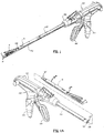
- a surgical instrument 500 includes a handle portion 510, a body portion 512, and a disposable loading unit ("DLU") 16.
- the handle portion 510 includes a stationary handle 514 and a movable handle or trigger 516.
- the movable handle 516 is movable in relation to the stationary handle 514 to actuate the surgical instrument 500.
- a control rod 520 is distally advanced from a distal end 501 of the body portion 512.
- the handle portion 510 and the body portion 512 may be constructed in the manner disclosed in U.S. Pat. No. 6,330,965 , which is hereby incorporated by reference in its entirety.
- the DLU 16 includes a tool assembly 17, a proximal body portion 200, and a mounting assembly 202. As shown in Fig. 1A , the body portion 200 has a proximal end 201 adapted to releasably engage distal end 501 of the surgical instrument 500. Although as shown in Fig. 1A , the DLU 16 is separable from the body portion 512 of the surgical instrument, in other embodiments, the cartridge itself may be removed from a tool assembly and replaced with a new cartridge. The proximal end 201 of the body portion 200 is linearly inserted into an open end 522 of the body portion 512 of the surgical instrument 500. Actuation of the DLU 16 is facilitated by translation of control rod 520, which engages a proximal end of drive assembly 212 ( Fig. 2 ), thereby causing the drive assembly 212 to translate correspondingly.
- the tool assembly 17 may pivot with respect to the longitudinal axis of the body portion 200.
- Mounting assembly 202 is pivotably secured to a distal end of the body portion 200, and is fixedly secured to a proximal end of tool assembly 17. Pivotal movement of the mounting assembly 202 about an axis perpendicular to a longitudinal axis of body portion 200 causes articulation of tool assembly 17 between a non-articulated position in which the longitudinal axis of tool assembly 17 is aligned with the longitudinal axis of body portion 200 and an articulated position in which the longitudinal axis of tool assembly 17 is disposed at an angle to the longitudinal axis of body portion 200.
- An indicator assembly 5 minimizes the potential of inadvertent reloading of the DLU 16 after cartridge 54 ( Fig. 2 ) has been spent.
- an indicator pin 10 is transitionable between a first position ( Fig. 3A ) and a second position ( Fig. 3B ) to indicate whether the cartridge 54 has already been spent.
- Other embodiments of the indicator assembly 5 are in accordance with the present disclosure. For example, although shown and described as including a single indicator pin 10, a greater number of such pins may be employed.
- the indicator pin 10 may extend from other surfaces of the cartridge 54 or alternatively from anvil 20.
- the length and extension of the indicator pin 10 is configured and adapted to maximize the viewability of the indicator pin 10 from multiple orientations.
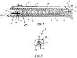
- the tool assembly 17 includes a cartridge assembly 18 and an anvil assembly 20.
- Anvil assembly 20 includes an anvil portion 28 having a plurality of staple deforming concavities 30 ( Fig. 4 ) and a cover plate 32 secured to a top surface of anvil portion 28.
- the cover plate 32 and the anvil portion 28 define a cavity 34 ( Fig. 4 ) therebetween which is dimensioned to receive a distal end of drive assembly 212 to inhibit pinching of tissue during actuation of DLU 16.
- a longitudinal slot 38 extends through anvil portion 28 to facilitate passage of a retention flange 40 of drive assembly 212.
- a camming surface 42 formed on anvil portion 28 is positioned to engage a pair of cam members 40a supported on retention flange 40 of drive assembly 212 to cause approximation of the anvil assembly 20 and the cartridge assembly 18.
- a pair of stabilizing members 50 engage a respective shoulder 52 formed on carrier 48 to inhibit the anvil portion 28 from sliding axially in relation to staple cartridge 54 as camming surface 42 is pivoted about pivot members 44.
- the cartridge assembly 18 includes carrier 48 defining an elongated support channel 56, which is dimensioned and configured to receive staple cartridge 54.
- a pair of support struts 62 formed on staple cartridge 54 are positioned to rest on side walls of carrier 48 to further stabilize staple cartridge 54 within support channel 56.
- Carrier 48 has slots 46 for receiving pivot members 44 of anvil portion 28 and allowing anvil portion 28 to move between spaced and approximated positions.
- Staple cartridge 54 includes retention slots 64 ( Fig. 2 ) for receiving a plurality of staples or fasteners 66 and pushers 68.
- a plurality of laterally spaced apart longitudinal slots 70 extend through staple cartridge 54 to accommodate upstanding cam wedges 72 of an actuation sled 74 ( Fig. 2 ), which is operatively coupled to the drive assembly 212.
- a central longitudinal slot 76 extends along substantially the length of staple cartridge 54 to facilitate passage of a knife blade 78 ( Fig. 4 ).
- drive assembly 212 abuts actuation sled 74 and pushes actuation sled 74 through longitudinal slots 70 of staple cartridge 54 to advance cam wedges 72 into sequential contact with pushers 68.
- Pushers 68 translate vertically along cam wedges 72 within fastener retention slots 64 and urge fasteners 66 from retention slots 64 into the staple deforming concavities 30 of anvil assembly 20.
- the indicator pin 10 is positioned within a channel 11 that extends through distal end 14 of the staple cartridge 54.
- the channel 11 may narrow toward the distal end 14 of the staple cartridge 54 such that distal translation of the indicator pin 10 through the channel 11 will frictionally secure the indicator pin 10 within the channel, thereby inhibiting proximal translation of the indicator pin 10 back through the channel 11 once the indicator pin 10 has been fully translated through the channel 11.
- the indicator pin 10 may be releasably locked within a ring 13.
- One or more frangible fingers 12 may operatively couple the indicator pin 10 to the ring 13.
- the force of the actuation sled 74 abutting the proximal end 10a of the indicator pin 10 will break the frangible fingers 12, thereby permitting distal translation of the indicator pin 11 through the channel 11.
- the surgical instrument 500 During use of the surgical instrument 500, a surgeon will place tissue (not shown) that is to be stapled between the anvil assembly 20 and the cartridge assembly 18 to join tissue therebetween. As the surgical instrument 500 is fired, the indicator assembly 5 transitions to a position indicating that surgical instrument 500 has been fired and the cartridge 54 has been spent. As discussed above, the indicator pin 10 extends from a surface and is readily viewable from multiple orientations. The surgical instrument 500 is removed from the surgical site, and if necessary, the DLU 16 is replaced with a DLU 16 including a cartridge 54 that is in a condition to be fired.
- the indicator assembly is shown being used with a surgical stapling device, the indicator assembly may be incorporated into any surgical device having a cartridge.
- the indicator assembly will provide notification that the cartridge has been spent, thereby alerting a user to provide a fresh cartridge. Therefore, the above description should not be construed as limiting, but merely as exemplifications of various embodiments. Those skilled in the art will envision other modifications within the scope and spirit of the claims appended hereto.
Abstract
A surgical instrument (500) comprising: a body portion (512); a loading unit (16) operatively coupled to the body portion (512), the loading unit (16) including a cartridge (54), the cartridge (54) housing a plurality of fasteners (66); a drive assembly (212) configured to translate through the cartridge (54) to eject the fasteners (66) from the cartridge (54); an indicator assembly (5) including a number of indicator pins (10), the indicator pins (10) being transitionable from a first position to a second position after ejection of the fasteners (66), the indicator pins (10) being substantially flush with a surface of the cartridge (54) when the indicator pins (10) are in the first position, and extending past the surface of the cartridge (54) when the indicator pins (10) are in the second position; and wherein the cartridge (54) includes a distal portion, and a longitudinally extending aperture (11) is defined within the distal portion, the indicator pins (10) being translatable through the aperture (11); characterised in that: the indicator assembly (5) further includes a ring (13), the ring (13) positioned within the aperture (11), the ring (13) disposed around the indicator pin (10), one or more frangible fingers (12) joining the indicator pins (10) and the ring (13), the one or more frangible fingers (12) inhibiting transitioning of the indicator pins (10) from the first to the second position prior to actuation of the surgical instrument (500), the one or more frangible fingers (12) breaking in response to actuation of the surgical instrument (500).
Description
- The present disclosure generally relates to a surgical instrument including a disposable loading unit. More particularly, this disclosure relates to a surgical stapling device providing an indication that the surgical stapling device has been fired.
- Surgical devices designed to grasp or clamp tissue between a pair of opposing jaws and then joining the tissue with surgical fasteners are well known in the art. In some instruments, a knife is provided to cut the tissue which has been joined by the fasteners. The fasteners are typically in the form of surgical staples, but two part fasteners formed of a material suitable for surgical use can also be used.
- Such instruments may include two elongated members adapted to capture or clamp tissue therebetween. Typically, one of the members carries a staple cartridge that houses a plurality of staples arranged in at least two lateral rows while the other member has an anvil defining a surface for forming the staple legs as the staples are driven from the staple cartridge. In some instruments, the closure of the two elongated members, or tool assembly, is effected by the actuation of a movable handle that moves a drive beam having a closure apparatus thereon into a contact surface of a tool assembly thereby actuating the tool assembly. A knife can travel between rows of stapes to longitudinally cut and/or open the stapled tissue between the rows of staples.
- In laparoscopic and/or endoscopic surgical procedures, the surgical procedure is performed through a small incision or through a narrow cannula inserted through a small entrance wound in a patient. In conventional or open procedures, surgeons directly access an operative site. Because of reduced patient trauma, shortened patient recovery periods and reduced cost, endoscopic procedures are preferred over open surgical procedures.
- Articulatable endoscopic stapling instruments including disposable loading units ("DLUs") or singlye use loading units ("SULUs") are known in the art. These instruments have provided significant clinical benefits to the field of endoscopic surgery. Nonethereless, there is a continuing need for surgical devices in this area.
- The present disclosure relates to a surgical instrument including a cartridge assembly. The surgical instrument is usable during many surgical procedures including minimally invasive surgical procedures. The cartridge assembly includes a plurality of fasteners that are ejectable from the cartridge. An indicator assembly provides an indication as to whether the cartridge has been used or not. In an embodiment, the indicator assembly includes an indicator pin that is transitionable from a first position to a second position after ejection of the fasteners, thereby providing visual indication that the fasteners have been ejected from the cartridge. The indicator pin may be inhibited from transitioning from the second position to the first position to inihibit inadvertent reloading of a spent cartridge.
- When the indicator pin is in the first position, the indicator pin is substantially flush with a surface of the cartridge. In the second position, the indicator pin extends past the surface of the cartridge, i.e., the indicator pin is not substantially flush with the surface of the cartridge. An actuation sled may distally translate through the cartridge, thereby causing ejection of the fasteners contained therein. The indicator pin may be positioned within a longitudinally extending aperture defined within the distal end of the cartridge. As the actuation sled is translated distally, the actuation sled will abut the indicator pin and force the indicator pin to translate distally, thereby transitioning the indicator pin to the second position to indicate that the fasteners have been ejected from the cartridge.
- The indicator assembly may include an assembly that inhibits premature transitioning of the indicator to the second position. For example, the indicator assembly may include a ring that is positioned within an aperture formed in the distal end of the cartridge. The ring is disposed around the indicator pin and releasably locks the indicator pin within the aperture. One or more frangible fingers may couple the indicator pin to the ring by breaking only in response to force resulting from the actuation sled of the drive assembly distally translating through the cartridge and pressing against a proximal end of the indicator pin, thereby allowing the indicator pin to translate distally.
- Once the indicator pin has been translated distally, the indicator pin remains extended. The longitudinally extending aperture in which the indicator pin is positioned may narrow toward the distal end of the cartridge, thereby creating an interference fit between the indicator pin and the longitudinally extending aperture, thereby frictionally securing the indicator pin the extended position.
- A method of performing a surgical procedure includes providing a surgical instrument including a cartridge, such as that described above. The indicator pin is operatively coupled to the tool assembly such that after actuation of the surgical instrument, a user is readily notified that the cartridge has been spent. During use, tissue that is to be fastened is placed between the anvil and the cartridge, and the surgical instrument is actuated. Once the surgical instrument is actuated, the indicator assembly transitions to a second position to provide visual indication that the surgical instrument has been fired. Because the indicator pin extends a distance from one of the cartridge or the anvil, the indicator pin is viewable from multiple orientations, thereby readily providing notification to the user that the cartridge has been spent.
- The various aspects of the present disclosure will be more readily understood from the following detailed description when read in conjunction with the appended figures.
- Various embodiments of the presently disclosed surgical instrument are disclosed herein with reference to the drawings, wherein:
-
FIG. 1 is a side perspective view a surgical instrument including a body portion and a disposable loading unit ("DLU") including a tool assembly; -
Fig. 1A is a side perspective view of the surgical instrument ofFig. 1 with the DLU separated from the body portion; -
Fig. 2 is a side perspective view of the distal end of DLU ofFig. 1 with parts separated; -
Fig. 3A is a side perspective view of the DLU ofFig. 1 shown in a first position; -
Fig. 3B is the DLU ofFig. 3A shown in a second position; -
Fig. 4 is a side cross-sectional view of the tool assembly ofFig. 1 ; and -
Fig. 5 is a side view of the distal end of the tool assembly ofFig. 1 . - Embodiments of the presently disclosed surgical instrument will now be described in detail with reference to the appended figures, in which like reference numerals designate identical or corresponding elements in each of the several views. In the following description, well known functions or constructions are not described in detail to avoid obscuring the present disclosure in unnecessary detail. As shown in the drawings and as described throughout the following description, and as is traditional when referring to relative positioning on an object, the term proximal refers to the end of the device that is closer to the user and the term "distal" refers to the end of the apparatus that is further from the user.
- A surgical instrument including a DLU including a cartridge having an indicator assembly to provide notification of the condition of the cartridge, i.e., whether the cartridge has been spent, will be described herein. As shown in
Figs. 1 and 1A , asurgical instrument 500 includes ahandle portion 510, abody portion 512, and a disposable loading unit ("DLU") 16. Thehandle portion 510 includes astationary handle 514 and a movable handle ortrigger 516. Themovable handle 516 is movable in relation to thestationary handle 514 to actuate thesurgical instrument 500. As themovable handle 516 and thestationary handle 514 are moved closer to one another, acontrol rod 520 is distally advanced from a distal end 501 of thebody portion 512. Thehandle portion 510 and thebody portion 512 may be constructed in the manner disclosed inU.S. Pat. No. 6,330,965 , which is hereby incorporated by reference in its entirety. - The
DLU 16 includes atool assembly 17, aproximal body portion 200, and a mountingassembly 202. As shown inFig. 1A , thebody portion 200 has aproximal end 201 adapted to releasably engage distal end 501 of thesurgical instrument 500. Although as shown inFig. 1A , theDLU 16 is separable from thebody portion 512 of the surgical instrument, in other embodiments, the cartridge itself may be removed from a tool assembly and replaced with a new cartridge. Theproximal end 201 of thebody portion 200 is linearly inserted into anopen end 522 of thebody portion 512 of thesurgical instrument 500. Actuation of theDLU 16 is facilitated by translation ofcontrol rod 520, which engages a proximal end of drive assembly 212 (Fig. 2 ), thereby causing the drive assembly 212 to translate correspondingly. - The
tool assembly 17 may pivot with respect to the longitudinal axis of thebody portion 200. Mountingassembly 202 is pivotably secured to a distal end of thebody portion 200, and is fixedly secured to a proximal end oftool assembly 17. Pivotal movement of the mountingassembly 202 about an axis perpendicular to a longitudinal axis ofbody portion 200 causes articulation oftool assembly 17 between a non-articulated position in which the longitudinal axis oftool assembly 17 is aligned with the longitudinal axis ofbody portion 200 and an articulated position in which the longitudinal axis oftool assembly 17 is disposed at an angle to the longitudinal axis ofbody portion 200. - An indicator assembly 5 (
Figs. 3A and 3B ) minimizes the potential of inadvertent reloading of theDLU 16 after cartridge 54 (Fig. 2 ) has been spent. As will be explained in greater detail below, at adistal end 14 of theDLU 16, anindicator pin 10 is transitionable between a first position (Fig. 3A ) and a second position (Fig. 3B ) to indicate whether the cartridge 54 has already been spent. Other embodiments of theindicator assembly 5 are in accordance with the present disclosure. For example, although shown and described as including asingle indicator pin 10, a greater number of such pins may be employed. Moreover, although shown and described as extending from the distal end of the cartridge 54, theindicator pin 10 may extend from other surfaces of the cartridge 54 or alternatively fromanvil 20. The length and extension of theindicator pin 10 is configured and adapted to maximize the viewability of theindicator pin 10 from multiple orientations. - Referring to
Fig. 2 , thetool assembly 17 includes acartridge assembly 18 and ananvil assembly 20.Anvil assembly 20 includes ananvil portion 28 having a plurality of staple deforming concavities 30 (Fig. 4 ) and acover plate 32 secured to a top surface ofanvil portion 28. Thecover plate 32 and theanvil portion 28 define a cavity 34 (Fig. 4 ) therebetween which is dimensioned to receive a distal end of drive assembly 212 to inhibit pinching of tissue during actuation ofDLU 16. A longitudinal slot 38 extends throughanvil portion 28 to facilitate passage of aretention flange 40 of drive assembly 212. Acamming surface 42 formed onanvil portion 28 is positioned to engage a pair of cam members 40a supported onretention flange 40 of drive assembly 212 to cause approximation of theanvil assembly 20 and thecartridge assembly 18. A pair of stabilizing members 50 engage a respective shoulder 52 formed oncarrier 48 to inhibit theanvil portion 28 from sliding axially in relation to staple cartridge 54 ascamming surface 42 is pivoted about pivot members 44. - The
cartridge assembly 18 includescarrier 48 defining an elongated support channel 56, which is dimensioned and configured to receive staple cartridge 54. Corresponding tabs 58 andslots 60 formed along staple cartridge 54 and elongated support channel 56, respectively, function to retain staple cartridge 54 at a fixed location within support channel 56. A pair of support struts 62 formed on staple cartridge 54 are positioned to rest on side walls ofcarrier 48 to further stabilize staple cartridge 54 within support channel 56.Carrier 48 has slots 46 for receiving pivot members 44 ofanvil portion 28 and allowinganvil portion 28 to move between spaced and approximated positions. - Staple cartridge 54 includes retention slots 64 (
Fig. 2 ) for receiving a plurality of staples orfasteners 66 andpushers 68. A plurality of laterally spaced apart longitudinal slots 70 extend through staple cartridge 54 to accommodate upstanding cam wedges 72 of an actuation sled 74 (Fig. 2 ), which is operatively coupled to the drive assembly 212. A central longitudinal slot 76 extends along substantially the length of staple cartridge 54 to facilitate passage of a knife blade 78 (Fig. 4 ). During operation, drive assembly 212 abutsactuation sled 74 and pushesactuation sled 74 through longitudinal slots 70 of staple cartridge 54 to advance cam wedges 72 into sequential contact withpushers 68.Pushers 68 translate vertically along cam wedges 72 withinfastener retention slots 64 andurge fasteners 66 fromretention slots 64 into thestaple deforming concavities 30 ofanvil assembly 20. - As shown in
Figs. 4 and 5 , theindicator pin 10 is positioned within a channel 11 that extends throughdistal end 14 of the staple cartridge 54. The channel 11 may narrow toward thedistal end 14 of the staple cartridge 54 such that distal translation of theindicator pin 10 through the channel 11 will frictionally secure theindicator pin 10 within the channel, thereby inhibiting proximal translation of theindicator pin 10 back through the channel 11 once theindicator pin 10 has been fully translated through the channel 11. Theindicator pin 10 may be releasably locked within aring 13. One or morefrangible fingers 12 may operatively couple theindicator pin 10 to thering 13. As theactuation sled 74 translates through the staple cartridge 54, the force of theactuation sled 74 abutting the proximal end 10a of theindicator pin 10 will break thefrangible fingers 12, thereby permitting distal translation of the indicator pin 11 through the channel 11. - During use of the
surgical instrument 500, a surgeon will place tissue (not shown) that is to be stapled between theanvil assembly 20 and thecartridge assembly 18 to join tissue therebetween. As thesurgical instrument 500 is fired, theindicator assembly 5 transitions to a position indicating thatsurgical instrument 500 has been fired and the cartridge 54 has been spent. As discussed above, theindicator pin 10 extends from a surface and is readily viewable from multiple orientations. Thesurgical instrument 500 is removed from the surgical site, and if necessary, theDLU 16 is replaced with aDLU 16 including a cartridge 54 that is in a condition to be fired. - It will be understood that various modifications may be made to the embodiments disclosed herein. Although the indicator assembly is shown being used with a surgical stapling device, the indicator assembly may be incorporated into any surgical device having a cartridge. The indicator assembly will provide notification that the cartridge has been spent, thereby alerting a user to provide a fresh cartridge. Therefore, the above description should not be construed as limiting, but merely as exemplifications of various embodiments. Those skilled in the art will envision other modifications within the scope and spirit of the claims appended hereto.
- The invention may be described by reference to the following numbered paragraphs:-
- 1. A surgical instrument comprising:
- a body portion;
- a loading unit operatively coupled to the body portion, the loading unit including a cartridge, the cartridge housing a plurality of fasteners;
- a drive assembly configured to translate through the cartridge to eject the fasteners from the cartridge; and
- an indicator assembly transitionable from a first position to a second position after ejection of the fasteners.
- 2. The surgical instrument of
paragraph 1, wherein the indicator assembly is inhibited from transitioning from the second position to the first position. - 3. The surgical instrument of
paragraph 1, wherein the indicator assembly includes an indicator pin, the indicator pin substantially flush with a surface of cartridge when the indicator assembly is in the first position, and extending past the surface of the cartridge when the indicator assembly is in the second position. - 4. The surgical instrument of paragraph 3, wherein distal translation of the drive assembly causes the indicator assembly to transition to the second position.
- 5. The surgical instrument of paragraph 3, wherein translation of the indicator pin is inhibited prior to ejection of the fasteners.
- 6. The surgical instrument of paragraph 3, wherein the cartridge includes a distal portion, and a longitudinally extending aperture is defined within the distal portion, the indicator pin translatable through the aperture.
- 7. The surgical instrument of paragraph 6, wherein the longitudinally extending aperture narrows from a proximal end to a distal end of the aperture.
- 8. The surgical instrument of paragraph 7, wherein distal translation of the indicator pin through the aperture frictionally secures the indicator pin within the aperture, thereby inhibiting proximal translation of the indicator pin back through the aperture.
- 9. The surgical instrument of
paragraph 1, wherein the loading unit is separable from the body portion. - 10. The surgical instrument of paragraph 6, wherein the indicator assembly further includes a ring, the ring positioned within the aperture, the ring disposed around the indicator pin, one or more frangible fingers joining the indictor pin and the ring, the one or more frangible fingers inhibiting transitioning of the indicator pin form the first to the second position prior to actuation of the surgical instrument, the one or more frangible fingers breaking in response to actuation of the surgical instrument.
- 11. A method of performing a surgical procedure comprising:
- providing a surgical instrument including:
- a body portion;
- a loading unit operatively coupled to the body portion, the loading unit including a cartridge, the cartridge housing a plurality of fasteners, and an anvil movable relative to the cartridge;
- a drive assembly translatable through the cartridge to eject the fasteners from the cartridge; and
- an indicator assembly transitionable from a first position to a second position after ejection of the fasteners;
- placing tissue between the cartridge and the anvil;
- actuating the surgical instrument to fasten the tissue placed between the cartridge and the anvil;
- observing the indicator assembly in the second position; and
- separating the loading unit from the surgical instrument.
- providing a surgical instrument including:
- 1. A surgical instrument comprising:
- a body portion;
- a loading unit operatively coupled to the body portion, the loading unit including a cartridge, the cartridge housing a plurality of fasteners;
- a drive assembly configured to translate through the cartridge to eject the fasteners from the cartridge; and
- an indicator assembly transitionable from a first position to a second position after ejection of the fasteners.
- 2. The surgical instrument of
paragraph 1, wherein the indicator assembly is inhibited from transitioning from the second position to the first position. - 3. The surgical instrument of
paragraph 1 or paragraph 2, wherein the indicator assembly includes an indicator pin, the indicator pin substantially flush with a surface of cartridge when the indicator assembly is in the first position, and extending past the surface of the cartridge when the indicator assembly is in the second position. - 4. The surgical instrument of paragraph 3, wherein distal translation of the drive assembly causes the indicator assembly to transition to the second position.
- 5. The surgical instrument of paragraph 3 or paragraph 4, wherein translation of the indicator pin is inhibited prior to ejection of the fasteners.
- 6. The surgical instrument of any of paragraphs 3 to 5, wherein the cartridge includes a distal portion, and a longitudinally extending aperture is defined within the distal portion, the indicator pin translatable through the aperture.
- 7. The surgical instrument of paragraph 6, wherein the longitudinally extending aperture narrows from a proximal end to a distal end of the aperture.
- 8. The surgical instrument of paragraph 7, wherein distal translation of the indicator pin through the aperture frictionally secures the indicator pin within the aperture, thereby inhibiting proximal translation of the indicator pin back through the aperture.
- 9. The surgical instrument of any preceding paragraph, wherein the loading unit is separable from the body portion.
- 10. The surgical instrument of paragraph 6, wherein the indicator assembly further includes a ring, the ring positioned within the aperture, the ring disposed around the indicator pin, one or more frangible fingers joining the indictor pin and the ring, the one or more frangible fingers inhibiting transitioning of the indicator pin form the first to the second position prior to actuation of the surgical instrument, the one or more frangible fingers breaking in response to actuation of the surgical instrument.
- 11. A method of performing a surgical procedure comprising:
- providing a surgical instrument including:
- a body portion;
- a loading unit operatively coupled to the body portion, the loading unit including a cartridge, the cartridge housing a plurality of fasteners, and an anvil movable relative to the cartridge;
- a drive assembly translatable through the cartridge to eject the fasteners from the cartridge; and
- an indicator assembly transitionable from a first position to a second position after ejection of the fasteners;
- placing tissue between the cartridge and the anvil;
- actuating the surgical instrument to fasten the tissue placed between the cartridge and the anvil;
- observing the indicator assembly in the second position; and
- separating the loading unit from the surgical instrument.
- providing a surgical instrument including:
Claims (6)
- A surgical instrument (500) comprising:a body portion (512);a loading unit (16) operatively coupled to the body portion (512), the loading unit (16) including a cartridge (54), the cartridge (54) housing a plurality of fasteners (66);a drive assembly (212) configured to translate through the cartridge (54) to eject the fasteners (66) from the cartridge (54);an indicator assembly (5) including a number of indicator pins (10), the indicator pins (10) being transitionable from a first position to a second position after ejection of the fasteners (66), the indicator pins (10) being substantially flush with a surface of the cartridge (54) when the indicator pins (10) are in the first position, and extending past the surface of the cartridge (54) when the indicator pins (10) are in the second position; andwherein the cartridge (54) includes a distal portion, and a longitudinally extending aperture (11) is defined within the distal portion, the indicator pins (10) being translatable through the aperture (11);characterised in that:the indicator assembly (5) further includes a ring (13), the ring (13) positioned within the aperture (11), the ring (13) disposed around the indicator pin (10), one or more frangible fingers (12) joining the indicator pins (10) and the ring (13), the one or more frangible fingers (12) inhibiting transitioning of the indicator pins (10) from the first to the second position prior to actuation of the surgical instrument (500), the one or more frangible fingers (12) breaking in response to actuation of the surgical instrument (500).
- The surgical instrument (500) of claim 1, wherein the indicator assembly (5) is inhibited from transitioning from the second position to the first position.
- The surgical instrument (500) of claim 1 or claim 2, wherein distal translation of the drive assembly (212) causes the indicator pins (10) to transition to the second position.
- The surgical instrument (500) of any preceding claim, wherein the longitudinally extending aperture (11) narrows from a proximal end to a distal end of the aperture (11).
- The surgical instrument (500) of claim 4, wherein distal translation of the indicator pins (10) through the aperture (11) frictionally secures the indicator pins (10) within the aperture (11), thereby inhibiting proximal translation of the indicator pins (10) back through the aperture (11).
- The surgical instrument (500) of any preceding claim, wherein the loading unit (16) is separable from the body portion (512).
Applications Claiming Priority (2)
| Application Number | Priority Date | Filing Date | Title |
|---|---|---|---|
| US13/325,364 US8967447B2 (en) | 2011-12-14 | 2011-12-14 | Surgical instrument including firing indicator |
| EP12196897.8A EP2604193B1 (en) | 2011-12-14 | 2012-12-13 | Surgical instrument including firing indicator |
Related Parent Applications (2)
| Application Number | Title | Priority Date | Filing Date |
|---|---|---|---|
| EP12196897.8A Division-Into EP2604193B1 (en) | 2011-12-14 | 2012-12-13 | Surgical instrument including firing indicator |
| EP12196897.8A Division EP2604193B1 (en) | 2011-12-14 | 2012-12-13 | Surgical instrument including firing indicator |
Publications (1)
| Publication Number | Publication Date |
|---|---|
| EP3243448A1 true EP3243448A1 (en) | 2017-11-15 |
Family
ID=47602902
Family Applications (2)
| Application Number | Title | Priority Date | Filing Date |
|---|---|---|---|
| EP12196897.8A Active EP2604193B1 (en) | 2011-12-14 | 2012-12-13 | Surgical instrument including firing indicator |
| EP17172912.2A Withdrawn EP3243448A1 (en) | 2011-12-14 | 2012-12-13 | Surgical instrument including firing indicator |
Family Applications Before (1)
| Application Number | Title | Priority Date | Filing Date |
|---|---|---|---|
| EP12196897.8A Active EP2604193B1 (en) | 2011-12-14 | 2012-12-13 | Surgical instrument including firing indicator |
Country Status (5)
| Country | Link |
|---|---|
| US (1) | US8967447B2 (en) |
| EP (2) | EP2604193B1 (en) |
| AU (1) | AU2012258496A1 (en) |
| CA (1) | CA2795839A1 (en) |
| ES (1) | ES2636677T3 (en) |
Families Citing this family (20)
| Publication number | Priority date | Publication date | Assignee | Title |
|---|---|---|---|---|
| US7552854B2 (en) | 2006-05-19 | 2009-06-30 | Applied Medical Resources Corporation | Surgical stapler with firing lock mechanism |
| WO2013173617A1 (en) | 2012-05-16 | 2013-11-21 | The Seaberg Company, Inc. | Safety needle |
| US20130334280A1 (en) * | 2012-06-14 | 2013-12-19 | Covidien Lp | Sliding Anvil/Retracting Cartridge Reload |
| EP3412222B1 (en) | 2013-03-14 | 2023-06-07 | Applied Medical Resources Corporation | Surgical stapler with partial pockets |
| EP3824819B1 (en) | 2013-03-15 | 2023-08-30 | Applied Medical Resources Corporation | Surgical stapler having actuation mechanism with rotatable shaft |
| US9820742B2 (en) | 2013-03-15 | 2017-11-21 | Applied Medical Resources Corporation | Surgical stapler with expandable jaw |
| WO2015134682A1 (en) | 2014-03-04 | 2015-09-11 | Maquet Cardiovascular Llc | Surgical implant and method and instrument for installing the same |
| US10499908B2 (en) | 2014-03-04 | 2019-12-10 | Maquet Cardiovascular Llc | Surgical implant and method and instrument for installing the same |
| JP6674908B2 (en) | 2014-06-11 | 2020-04-01 | アプライド メディカル リソーシーズ コーポレイション | Surgical stapler with circumferential firing |
| ES2797755T3 (en) | 2014-09-15 | 2020-12-03 | Applied Med Resources | Surgical stapler with self-adjusting staple height |
| KR20240027156A (en) | 2015-08-06 | 2024-02-29 | 어플라이드 메디컬 리소시스 코포레이션 | Surgical stapler having locking articulation joint |
| US20170056047A1 (en) * | 2015-09-02 | 2017-03-02 | MicroAire Surgical Instruments, LLC. | Endoscopic Surgical Devices and Other Surgical Devices |
| JP7015246B2 (en) | 2016-04-12 | 2022-02-02 | アプライド メディカル リソーシーズ コーポレイション | Surgical stapler with range of motion |
| EP4144304A1 (en) | 2016-04-12 | 2023-03-08 | Applied Medical Resources Corporation | Surgical stapler having a powered handle |
| AU2017250264B2 (en) | 2016-04-12 | 2021-12-02 | Applied Medical Resources Corporation | Reload shaft assembly for surgical stapler |
| JP7423538B2 (en) | 2018-02-27 | 2024-01-29 | アプライド メディカル リソーシーズ コーポレイション | surgical stapler with electric handle |
| CA3131187A1 (en) | 2019-02-27 | 2020-09-03 | Applied Medical Resources Corporation | Surgical stapling instrument having a two-position lockout mechanism |
| AU2020253285A1 (en) | 2019-03-29 | 2021-09-30 | Applied Medical Resources Corporation | Reload cover for surgical stapling system |
| CA3195757A1 (en) | 2020-10-29 | 2022-05-05 | Jonathan VON STEIN | Actuation shaft retention mechanism for surgical stapler |
| JP2023548141A (en) | 2020-10-29 | 2023-11-15 | アプライド メディカル リソーシーズ コーポレイション | surgical stapler with electric handle |
Citations (2)
| Publication number | Priority date | Publication date | Assignee | Title |
|---|---|---|---|---|
| US6330965B1 (en) | 1997-09-23 | 2001-12-18 | United States Surgical Corporation | Surgical stapling apparatus |
| EP2090255A1 (en) * | 2008-02-14 | 2009-08-19 | Ethicon Endo-Surgery, Inc. | Disposable loading unit with user feedback features and surgical instrument for use therewith |
Family Cites Families (13)
| Publication number | Priority date | Publication date | Assignee | Title |
|---|---|---|---|---|
| US5289963A (en) | 1991-10-18 | 1994-03-01 | United States Surgical Corporation | Apparatus and method for applying surgical staples to attach an object to body tissue |
| US5383880A (en) | 1992-01-17 | 1995-01-24 | Ethicon, Inc. | Endoscopic surgical system with sensing means |
| US5503320A (en) | 1993-08-19 | 1996-04-02 | United States Surgical Corporation | Surgical apparatus with indicator |
| US5685474A (en) * | 1994-10-04 | 1997-11-11 | United States Surgical Corporation | Tactile indicator for surgical instrument |
| US6594552B1 (en) | 1999-04-07 | 2003-07-15 | Intuitive Surgical, Inc. | Grip strength with tactile feedback for robotic surgery |
| US7464847B2 (en) | 2005-06-03 | 2008-12-16 | Tyco Healthcare Group Lp | Surgical stapler with timer and feedback display |
| US7784663B2 (en) | 2005-03-17 | 2010-08-31 | Ethicon Endo-Surgery, Inc. | Surgical stapling instrument having load sensing control circuitry |
| US20070078484A1 (en) | 2005-10-03 | 2007-04-05 | Joseph Talarico | Gentle touch surgical instrument and method of using same |
| US20110290856A1 (en) | 2006-01-31 | 2011-12-01 | Ethicon Endo-Surgery, Inc. | Robotically-controlled surgical instrument with force-feedback capabilities |
| US8161977B2 (en) | 2006-01-31 | 2012-04-24 | Ethicon Endo-Surgery, Inc. | Accessing data stored in a memory of a surgical instrument |
| US8062236B2 (en) | 2006-02-02 | 2011-11-22 | Tyco Healthcare Group, Lp | Method and system to determine an optimal tissue compression time to implant a surgical element |
| US20080296346A1 (en) | 2007-05-31 | 2008-12-04 | Shelton Iv Frederick E | Pneumatically powered surgical cutting and fastening instrument with electrical control and recording mechanisms |
| US8409223B2 (en) | 2008-08-29 | 2013-04-02 | Covidien Lp | Endoscopic surgical clip applier with clip retention |
-
2011
- 2011-12-14 US US13/325,364 patent/US8967447B2/en active Active
-
2012
- 2012-11-19 CA CA2795839A patent/CA2795839A1/en not_active Abandoned
- 2012-11-29 AU AU2012258496A patent/AU2012258496A1/en not_active Abandoned
- 2012-12-13 EP EP12196897.8A patent/EP2604193B1/en active Active
- 2012-12-13 ES ES12196897.8T patent/ES2636677T3/en active Active
- 2012-12-13 EP EP17172912.2A patent/EP3243448A1/en not_active Withdrawn
Patent Citations (2)
| Publication number | Priority date | Publication date | Assignee | Title |
|---|---|---|---|---|
| US6330965B1 (en) | 1997-09-23 | 2001-12-18 | United States Surgical Corporation | Surgical stapling apparatus |
| EP2090255A1 (en) * | 2008-02-14 | 2009-08-19 | Ethicon Endo-Surgery, Inc. | Disposable loading unit with user feedback features and surgical instrument for use therewith |
Also Published As
| Publication number | Publication date |
|---|---|
| EP2604193A1 (en) | 2013-06-19 |
| CA2795839A1 (en) | 2013-06-14 |
| EP2604193B1 (en) | 2017-07-05 |
| ES2636677T3 (en) | 2017-10-06 |
| US8967447B2 (en) | 2015-03-03 |
| AU2012258496A1 (en) | 2013-07-04 |
| US20130153632A1 (en) | 2013-06-20 |
Similar Documents
| Publication | Publication Date | Title |
|---|---|---|
| US8967447B2 (en) | Surgical instrument including firing indicator | |
| US11375998B2 (en) | Tissue stop for surgical instrument | |
| EP3120783B1 (en) | Small diameter cartridge design for a surgical stapling instrument | |
| CN107635481B (en) | Minor diameter surgical suturing device | |
| US10034666B2 (en) | Tissue stop for surgical instrument | |
| EP2682061B1 (en) | T-slot tilt anvil for circular stapling instrument | |
| EP2253277B1 (en) | Surgical Stapling Apparatus With Locking Mechanism | |
| US20180125484A1 (en) | Loading unit for surgical instruments with low profile pushers | |
| EP2679172A1 (en) | Surgical instrument and bushing | |
| EP2783639A2 (en) | Micro surgical instrument and loading unit for use therewith | |
| EP2679171A1 (en) | Surgical instrument and bushing | |
| EP3922192A2 (en) | Alignment pin assembly for surgical stapler | |
| US20220000475A1 (en) | Surgical stapling device with knife blade lock | |
| EP1813197A2 (en) | Surgical stapling apparatus with locking mechanism | |
| CN112168259A (en) | Circular stapling instrument | |
| EP3494899A2 (en) | Surgical instrument with imaging device | |
| EP3949869A1 (en) | Surgical stapling device and fastener for pathological exam | |
| AU2015202577B2 (en) | Tissue stop for surgical instrument |
Legal Events
| Date | Code | Title | Description |
|---|---|---|---|
| PUAI | Public reference made under article 153(3) epc to a published international application that has entered the european phase |
Free format text: ORIGINAL CODE: 0009012 |
|
| AC | Divisional application: reference to earlier application |
Ref document number: 2604193 Country of ref document: EP Kind code of ref document: P |
|
| AK | Designated contracting states |
Kind code of ref document: A1 Designated state(s): AL AT BE BG CH CY CZ DE DK EE ES FI FR GB GR HR HU IE IS IT LI LT LU LV MC MK MT NL NO PL PT RO RS SE SI SK SM TR |
|
| STAA | Information on the status of an ep patent application or granted ep patent |
Free format text: STATUS: THE APPLICATION IS DEEMED TO BE WITHDRAWN |
|
| 18D | Application deemed to be withdrawn |
Effective date: 20180516 |