EP3243071B1 - Method of obtaining or maintaining optical transmittance into deaerated liquid - Google Patents
Method of obtaining or maintaining optical transmittance into deaerated liquid Download PDFInfo
- Publication number
- EP3243071B1 EP3243071B1 EP16735460.4A EP16735460A EP3243071B1 EP 3243071 B1 EP3243071 B1 EP 3243071B1 EP 16735460 A EP16735460 A EP 16735460A EP 3243071 B1 EP3243071 B1 EP 3243071B1
- Authority
- EP
- European Patent Office
- Prior art keywords
- ultrasonic energy
- transference medium
- light
- light transference
- liquid
- Prior art date
- Legal status (The legal status is an assumption and is not a legal conclusion. Google has not performed a legal analysis and makes no representation as to the accuracy of the status listed.)
- Active
Links
Images




Classifications
-
- G—PHYSICS
- G02—OPTICS
- G02F—OPTICAL DEVICES OR ARRANGEMENTS FOR THE CONTROL OF LIGHT BY MODIFICATION OF THE OPTICAL PROPERTIES OF THE MEDIA OF THE ELEMENTS INVOLVED THEREIN; NON-LINEAR OPTICS; FREQUENCY-CHANGING OF LIGHT; OPTICAL LOGIC ELEMENTS; OPTICAL ANALOGUE/DIGITAL CONVERTERS
- G02F1/00—Devices or arrangements for the control of the intensity, colour, phase, polarisation or direction of light arriving from an independent light source, e.g. switching, gating or modulating; Non-linear optics
- G02F1/01—Devices or arrangements for the control of the intensity, colour, phase, polarisation or direction of light arriving from an independent light source, e.g. switching, gating or modulating; Non-linear optics for the control of the intensity, phase, polarisation or colour
- G02F1/11—Devices or arrangements for the control of the intensity, colour, phase, polarisation or direction of light arriving from an independent light source, e.g. switching, gating or modulating; Non-linear optics for the control of the intensity, phase, polarisation or colour based on acousto-optical elements, e.g. using variable diffraction by sound or like mechanical waves
- G02F1/113—Circuit or control arrangements
-
- G—PHYSICS
- G01—MEASURING; TESTING
- G01N—INVESTIGATING OR ANALYSING MATERIALS BY DETERMINING THEIR CHEMICAL OR PHYSICAL PROPERTIES
- G01N21/00—Investigating or analysing materials by the use of optical means, i.e. using sub-millimetre waves, infrared, visible or ultraviolet light
- G01N21/01—Arrangements or apparatus for facilitating the optical investigation
- G01N21/15—Preventing contamination of the components of the optical system or obstruction of the light path
-
- B—PERFORMING OPERATIONS; TRANSPORTING
- B08—CLEANING
- B08B—CLEANING IN GENERAL; PREVENTION OF FOULING IN GENERAL
- B08B17/00—Methods preventing fouling
- B08B17/02—Preventing deposition of fouling or of dust
-
- B—PERFORMING OPERATIONS; TRANSPORTING
- B08—CLEANING
- B08B—CLEANING IN GENERAL; PREVENTION OF FOULING IN GENERAL
- B08B3/00—Cleaning by methods involving the use or presence of liquid or steam
- B08B3/04—Cleaning involving contact with liquid
- B08B3/10—Cleaning involving contact with liquid with additional treatment of the liquid or of the object being cleaned, e.g. by heat, by electricity or by vibration
- B08B3/12—Cleaning involving contact with liquid with additional treatment of the liquid or of the object being cleaned, e.g. by heat, by electricity or by vibration by sonic or ultrasonic vibrations
-
- B—PERFORMING OPERATIONS; TRANSPORTING
- B08—CLEANING
- B08B—CLEANING IN GENERAL; PREVENTION OF FOULING IN GENERAL
- B08B9/00—Cleaning hollow articles by methods or apparatus specially adapted thereto
- B08B9/02—Cleaning pipes or tubes or systems of pipes or tubes
- B08B9/027—Cleaning the internal surfaces; Removal of blockages
-
- G—PHYSICS
- G01—MEASURING; TESTING
- G01N—INVESTIGATING OR ANALYSING MATERIALS BY DETERMINING THEIR CHEMICAL OR PHYSICAL PROPERTIES
- G01N21/00—Investigating or analysing materials by the use of optical means, i.e. using sub-millimetre waves, infrared, visible or ultraviolet light
- G01N21/01—Arrangements or apparatus for facilitating the optical investigation
-
- G—PHYSICS
- G01—MEASURING; TESTING
- G01N—INVESTIGATING OR ANALYSING MATERIALS BY DETERMINING THEIR CHEMICAL OR PHYSICAL PROPERTIES
- G01N21/00—Investigating or analysing materials by the use of optical means, i.e. using sub-millimetre waves, infrared, visible or ultraviolet light
- G01N21/01—Arrangements or apparatus for facilitating the optical investigation
- G01N21/15—Preventing contamination of the components of the optical system or obstruction of the light path
- G01N2021/154—Ultrasonic cleaning
Definitions
- Measurement of parameters in liquids using optical sensors is commonplace. Reliable measurement of such parameters generally requires light to pass into the liquid, which generally requires light to first pass through a reasonably transparent medium, e . g ., a light transference medium. Reliability issues can arise in the event of obstruction of optical transference through the medium, which may be caused by particulate matter.
- boiler liquids are deaerated liquids that have unique features.
- Some unique features of boiler liquids include having very low levels of dissolved oxygen (e . g ., less than 10 ppb dissolved oxygen in conventional boiler feedwater) and having a pH ranging from 9 to 11.
- dissolved oxygen e. g ., less than 10 ppb dissolved oxygen in conventional boiler feedwater
- a form of treatment control based on light detection and/or measurement e.g., fluorometry
- some amount of corrosion will occur over time and deposit in the form of particulate matter onto a light transference medium, thereby causing some amount of optical obstruction of the light transference medium.
- the unique conditions of deaerated liquids, particularly boiler liquid present a challenge to the user when a light transference medium becomes optically obstructed.
- optical obstruction can be altogether prevented, and if optical obstruction occurs, it can be removed without disrupting detection, measurement, and/or treatment control via the light transference.
- WO2014/060023 A1 discloses a method for ultrasonic cavitation cleaning of an optical window in an analysis system in a process line containing process liquid, the method including subjecting the window to ultrasonic signals.
- US6324900 B1 discloses a method for optically measuring the transparency of a liquid by means of a turbidity analyser, wherein ultrasound waves are generated in all directions around the emitting and receiving optical/liquid interfaces in contact with the liquid, thereby cleaning the interface surfaces.
- US2009/032733 A1 discloses an apparatus, for measuring the amount of a material present in a liquid, comprising a measurement chamber with an optical window for transmitting both excitation light to the liquid and fluorescent light to a detector. An ultrasonic transducer for cleaning the optical window is coupled to the measurement chamber.
- a method of obtaining, or of maintaining, optical transference into deaerated liquid in contact with a light transference medium comprises applying ultrasonic energy at a wavelength ( ⁇ ) into deaerated liquid in contact with a light transference medium.
- the ultrasonic energy at wavelength ( ⁇ ) originates at a distance (d) from an optical signal transmitted into the light transference medium such that optical transference into the deaerated liquid via the light transference medium is obtained or maintained.
- a method of maintaining optical transference into deaerated (e.g., degassed) liquid in contact with a light transference medium according to the invention is defined in independent claim 1.
- liquid is deaerated prior to being utilized in a heating application (e.g., a boiler).
- Liquid is generally deaerated in an attempt to minimize corrosion of metals that come in contact with the steam and/or liquid.
- Illustrative deaerated liquids include, but are not limited to, deaerated boiler make-up feedwater and boiler liquid, which further includes boiler blowdown liquid and boiler condensate liquid.
- deaeratedboiler make-up feedwater is used to describe the boiler make-up feedwater that has undergone a deaeration process. The term is not used to describe the various boiler liquids, as it is understood by those skilled in the art that boiler liquids have already undergone a deaeration process prior to becoming boiler liquid.
- controller refers to an electronic device having components such as a processor, memory device, digital storage medium, cathode ray tube, liquid crystal display, plasma display, touch screen, or other monitor, and/or other components. Controllers include, for example, an interactive interface that guides a user, provides prompts to the user, or provides information to the user regarding any portion of the method of the invention. Such information may include, for example, building of calibration models, data collection of one or more parameters, measurement location(s), management of resulting data sets, etc.
- the controller is preferably operable for integration and/or communication with one or more application-specific integrated circuits, programs, computer-executable instructions or algorithms, one or more hard-wired devices, wireless devices, and/or one or more mechanical devices such as liquid handlers, hydraulic arms, servos, or other devices. Moreover, the controller is operable to integrate feedback, feed-forward, or predictive loop(s) resulting from, inter alia, the parameters measured by practicing the method(s) of the present disclosure. Some or all of the controller system functions may be at a central location, such as a network server, for communication over a local area network, wide area network, wireless network, extranet, the Internet, microwave link, infrared link, and the like, and any combinations of such links or other suitable links. In addition, other components such as a signal conditioner or system monitor may be included to facilitate signal transmission and signal-processing algorithms.
- the controller is operable to implement the method of the invention in a semi-automated or fully-automated fashion.
- the controller is operable to implement the method in a manual or semi-manual fashion.
- Data transmission of any of the measured parameters or signals to a user, chemical pumps, alarms, or other system components is accomplished using any suitable device, such as a wired or wireless network, cable, digital subscriber line, internet, etc.
- Any suitable interface standard(s) such as an ethernet interface, wireless interface (e . g ., IEEE 802.lla/b/g/n, 802.16, Bluetooth, optical, infrared, other radiofrequency, any other suitable wireless data transmission method, and any combinations of the foregoing), universal serial bus, telephone network, the like, and combinations of such interfaces/connections may be used.
- the term "network" encompasses all of these data transmission methods.
- any of the components, devices, sensors, etc., herein described may be connected to one another and/or the controller using the above-described or other suitable interface or connection.
- information (collectively referring to all of the inputs or outputs generated by the method of the invention) is received from the system and archived.
- information is processed according to a timetable or schedule.
- information is processed in real-time.
- Such real-time reception may also include, for example, "streaming data" over a computer network.
- control scheme refers to providing output based on input from a controller as defined herein.
- optical and “light” are used interchangeably herein.
- Utilization of the phrase “into deaerated liquid” is intended to cover light transmission in any direction between the deaerated liquid, the light transference medium, a light source, and/or a light detector.
- the optical signal may originate from within the deaerated liquid and be transferred to a sensor via the light transference medium (e.g., fluorometric emission), or from a light source through the light transference medium and into the deaerated liquid (e.g., fluorometric excitation).
- the optical signal comprises a fluorometric excitation and/or emission.
- the method is directed to obtaining or maintaining optical transference into deaerated liquid in contact with a light transference medium.
- the method can be utilized to remove obstructions that may be present on the light transference medium. Removal of obstruction from the light transference medium sufficient to allow for optical transference, thereby allowing for performance of an optical measurement of the deaerated liquid, is also achieved by the method of the present invention.
- An advantage of the present invention is that the method can be performed without interrupting the process responsible for supplying the deaerated liquid. For example, a boiler and its related treatment processes can continue to operate during performance of the method described herein.
- Ultrasonic energy is applied into deaerated liquid in contact with a light transference medium.
- the ultrasonic energy is applied to effectuate removal of optical obstruction that may be present on the light transference medium, particularly at a location of the light transference medium where an optical signal passes through, or should pass through.
- the deaerated liquid in contact with the light transference medium is flowing across the light transference medium as defined herein.
- the liquid may do so under conditions described as laminar, turbulent, and/or transitional flow.
- the deaerated liquid may have a Reynolds number ranging from 0 to 4000, including from 400 to 3000 or from 800 to 2300
- the ultrasonic energy may originate upstream or downstream from a location of a light transference medium where an optical signal passes through, or should pass through.
- the ultrasonic energy originates upstream from a location of a light transference medium where an optical signal passes through, or should pass through.
- the ultrasonic energy may have a frequency ranging from 20 kHz to 200 kHz. In some embodiments, the ultrasonic energy has a frequency ranging from 20 kHz to 80 kHz. In further embodiments, the ultrasonic energy has a frequency ranging from 30 kHz to 60 kHz, which includes 40 kHz. In even further embodiments, the ultrasonic energy has a frequency ranging from 25 kHz to 30 kHz, which includes 28 kHz.
- the ultrasonic energy is applied at a rate of from 1 W/cm 2 /sec to 400 W/cm 2 /sec.
- the ultrasonic energy may be applied at a rate of from 1 W/cm 2 /sec, or from 10 W/cm 2 /sec, or from 50 W/cm 2 /sec, or from 100 W/cm 2 /sec, to 400 W/cm 2 /sec, or to 300 W/cm 2 /sec, or to 200 W/cm 2 /sec.
- the wavelength of the ultrasonic energy is dependent upon the frequency and the velocity of the ultrasonic energy, which is essentially constant.
- the frequency, and therefore the wavelength is chosen so as to provide enough energy to prevent or remove particulate matter that may become deposited onto a light transference medium in contact with deaerated liquid.
- the frequency of the ultrasonic energy will be sufficient to remove such particulate matter, or prevent the particulate matter from depositing onto the light transference medium, while not damaging the light transference medium.
- a user may attempt to minimize or prevent damage to the light transference medium by utilizing one or more of several modifications discussed herein.
- the ultrasonic energy originates at a distance (d) from an optical signal transmitted into the light transference medium, which is preferably set to optimize the energy applied into the deaerated liquid at a point relative to the light transference medium, to effectively obtain or maintain light transference.
- the distance (d) is defined by Formula 1 herein.
- the tip of the ultrasonic probe is located at a distance (d) such that particulate matter deposited onto the light transference medium becomes dislodged, thereby maintaining optical transference into the deaerated liquid in contact with the light transference medium.
- the distance (d) within certain ranges defined herein, is thereby causing the ultrasonic energy to "originate" from the distance (d).
- the ultrasonic energy originates at a distance of from 30% to 70%, or from 35 % to 65 %, or from 40% to 60%, of the wavelength of the ultrasonic energy. In other examples, the ultrasonic energy originates at a distance from an optical signal transmitted into the light transference medium of from 80% to 120%, or from 85% to about 115%, or from 90% to 110%, of the wavelength of the ultrasonic energy. In certain examples, the ultrasonic energy originates at a distance of from 130% to 170%, or from 135% to 165%, or from 140% to 160%, of the wavelength of the ultrasonic energy.
- the ultrasonic energy originates at a distance from an optical signal transmitted into the light transference medium of from 180% to 220%, or from 185% to 215%, or from 190% to 210%, of the wavelength of the ultrasonic energy. In certain examples, the ultrasonic energy originates at a distance of from 230% to 270%, or from 235% to 265%, or from 240% to 260%, of the wavelength of the ultrasonic energy. In other examples, the ultrasonic energy originates at a distance from an optical signal transmitted into the light transference medium of from 280% to 320%, or from 285% to 315%, or from 290% to 310%, of the wavelength of the ultrasonic energy.
- the ultrasonic energy originates at a distance of from 330% to 370%, or from 335% to 365%, or from 40% to 360%, of the wavelength of the ultrasonic energy. In other examples, the ultrasonic energy originates at a distance from an optical signal transmitted into the light transference medium of from 380% to 420%, or from 385% to 415%, or from 390% to 410%, of the wavelength of the ultrasonic energy. In certain examples, the ultrasonic energy originates at a distance of from 430% to 470%, or from 435% to 465%, or from 440% to 460%, of the wavelength of the ultrasonic energy. In other examples, the ultrasonic energy originates at a distance from an optical signal transmitted into the light transference medium of from 480% to 520%, or from 485% to 515%, or from 490% to 510%, of the wavelength of the ultrasonic energy.
- a parameter of the deaerated liquid in contact with the light transference medium is measured by transmitting the optical signal into the deaerated liquid via the light transference medium, and detecting a response.
- the parameter is fluorescence, light absorbance, temperature, chemiluminescence, optical scattering (e.g., Rayleigh, Mie, and Raman scatter), imaging, transmittance, particle size, particle count, or turbidity, or any combination thereof.
- the method is a clean-in-place method.
- a clean-in-place method does not require disassembly of the system in order to conduct the method.
- the light transference medium is not removed from the system, and the system is not disconnected for the purpose of accessing the light transference medium.
- treatment of the deaerated liquid is controlled by utilizing the measured parameter in a control scheme.
- Treatment of the deaerated liquid may include, but is not limited to, at least one of physical treatment and chemical treatment.
- physical treatment include adjustment of any of the following parameters of the deaerated liquid: temperature, pressure, physical phase, flow rate ( e.g., circulation, blowdown, and/or make-up), flow path, and mixing.
- chemical treatment include adjustment of any of the following parameters, all related to a treatment chemical: chemical species selection, chemical species concentration, chemical species dosage rate, chemical species dosage location, and deaeration completeness.
- the measured parameter is inputted into a control scheme.
- the control scheme is generally an automated method that inputs a plurality of several measured parameters and operates several process devices, e . g ., pumps, valves, etc.
- a certain measured parameter may indicate that treatment chemical concentration has fallen outside a lower tolerance limit.
- the measured parameter may trigger the control scheme to operate a feed pump, which in turn adds treatment chemical to the process.
- the optical transference through the light transference medium is at least partially obstructed by particulate matter or scaling.
- the particulate matter may comprise a metal oxide.
- the light transference medium is obstructed by deposition of a chemical species comprising iron, copper, manganese, titanium, chromium, nickel, calcium, magnesium, oxide, phosphate, carbonate, or silicate, or any combination thereof.
- the light transference medium is obstructed by scale comprising calcium, magnesium, phosphate, carbonate, or silicate, or any combination thereof.
- the particulate deposition may comprise particulate matter found in raw water, e.g., mud, sand, silt, etc.
- the deaerated liquid may be conditioned prior to contacting the light transference medium.
- the deaerated liquid may be "enthalpy-rich.”
- the deaerated liquid may be conditioned such that a portion of the enthalpy (measured in the form of temperature and pressure) are removed prior to the deaerated liquid contacting the light transference medium.
- the deaerated liquid in contact with the light transference medium has a temperature of from -6.6 °C to 93.3 °C, corresponding to 20°F to 200°F, including from 40°F to 150°F, and including from 60°F to 130°F.
- the deaerated liquid in contact with the light transference medium has a pressure of from 34.47 kPa to 689.48 kPa, corresponding to from 5 to 100 psi, including from 10 psi to 70 psi, and including from 15 psi to 50 psi.
- the timing of the application of the ultrasonic energy to the deaerated liquid may take any one or more of several forms.
- the ultrasonic energy is continuously streamed into the deaerated liquid, which preferably includes while the system utilizing the deaerated liquid is operational.
- the ultrasonic energy is applied intermittently, e . g ., for a timed duration at timed intervals.
- the ultrasonic energy is applied on an as-needed basis, which can be determined, e.g., by comparing historical data related to the relevant sensor and light transference medium. For example, if obstruction of the light transference medium grows to an unacceptable value, e.g., a setpoint of from 1 to 5% obstruction, ultrasonic energy is then applied to the wetted surface of the light transference medium as described herein.
- Examples of light transference media include a flow cell, an optical window, a reflective surface, a refractive surface, a dispersive element, a filtering element, and an optical fiber sensor head.
- the light transference medium is generally constructed of a material that is transparent or nearly transparent and having a hardness of at least about 7 on the Mohs scale.
- transparent or nearly transparent refers to the ability of light to pass through a substance sufficient to use light for detection and/or measurement purposes as discussed herein, which includes transparency as defined by ASTM D1746.
- the light transference medium is constructed of quartz, sapphire, diamond, or boron nitride.
- the light transference medium is constructed of any suitable transparent or nearly transparent composition, and is coated with a transparent or nearly transparent substance having a hardness of at least about 7 on the Mohs scale.
- the light transference medium may be constructed of a substance having a Mohs scale hardness of at least about 7 ( e . g ., quartz), and then coated with a substance having an even higher Mohs scale rating.
- the coating substance has a Mohs scale rating of from 8 to 10, or from 9 to 10, or 10.
- substances suitable for coating a light transference medium include, but are not limited to, diamond, titanium diboride, boron nitride, and sapphire.
- the light transference medium takes the form of a reflective surface.
- an optical window may be utilized in concert with the reflective surface to provide observation from outside the deaerated liquid.
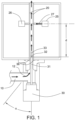
- FIG. 1 illustrates a system capable of performing the inventive method.
- a deaerated liquid 10 which flows in a direction 12, contacts a light transference medium 20.
- Light transference medium 20 is a flow cell, and deaerated liquid 10 flows through the flow cell via direction 12.
- a light source 25 and a detector 26 are located so as to transmit an optical signal 27 through light transference medium 20 and deaerated liquid 10, and detect the resulting behavior caused by the transmitted optical signal 27, which may include fluorescence, light absorbance, temperature, chemiluminescence, optical scattering ( e . g ., Rayleigh, Mie, and Raman scatter), imaging, transmittance, particle size, particle count, turbidity, and combinations thereof.
- optical scattering e . g ., Rayleigh, Mie, and Raman scatter
- An ultrasonic transducer 30 is operably attached to an ultrasonic probe 31 having a tip 32 that emits ultrasonic energy 33 at a wavelength ( ⁇ ), with tip 32 being located at a distance (d) from the optical signal 27, with distance (d) being defined by Formula 1 presented herein.
- the ultrasonic probe 31 may be positioned such that tip 32 emits ultrasonic energy 33 at an angle ⁇ of from 0 to about 45 degrees, or to about 35 degrees, or to about 25 degrees, or to about 15 degrees, or to about 5 degrees, as illustrated.
- the ultrasonic probe 31 is positioned such that tip 32 projects ultrasonic energy 33 substantially in the direction of flow 12 of deaerated liquid 10 across light transference medium 20.
- seal 36 is constructed of an elastomer.
- elastomers include, but are not limited to, nitrile-butadiene rubber ("nitrile”), hydrogenated nitrile-butadiene rubber, ethylene propylene diene monomer (“EPDM”), silicone, fluoroelastomer, and polychloroprene.
- FIG. 2 illustrates an example, wherein the tip 32 of the ultrasonic probe 31 is positioned so as to create an offset X from light transference medium 20.
- Utilization of offset X can be of particular importance to allow sufficient ultrasonic energy at wavelength ( ⁇ ) into the light transference medium when a relatively soft material (e . g ., seal 36) is present in the direction of the ultrasonic energy.
- the ultrasonic energy will be less likely to be dampened by the relatively soft material due to the low energy level at the location of the relatively soft material.
- the distance (d) should be measured from a point beyond the relatively soft material to light transference medium 20, as illustrated in FIG. 2 .
- FIG. 3 illustrates yet another example of a system capable of performing the inventive method.
- Light transference medium 20 takes the form of an optical window of a combination light source/detector 25/26, and deaerated liquid 10 flows across the optical window.
- Combination light source/detector 25/26 is located so as to transmit an optical signal 27 through light transference medium 20 (the optical window) and into the deaerated liquid 10, and detect the resulting behavior caused by optical signal 27, which may include fluorescence, light absorbance, temperature, chemiluminescence, optical scattering ( e .
- FIG. 3 shows an example utilizing a combination light source/detector 25/26, a person skilled in the art will readily recognize that the light source and the detector may be separate units operably connected to a control unit (not shown).
- An ultrasonic transducer 30 is operably attached to an ultrasonic probe 31 having a tip 32 that emits ultrasonic energy 33, with tip 32 being located at a distance (d) from the optical signal 27, with distance (d) defined by Formula 1 presented herein.
- FIG. 4 illustrates a further example of a system capable of performing the inventive method is illustrated.
- Light transference medium 20 includes a transparent portion 20a and an optional reflective portion 20b, and deaerated liquid 10 contacts each of transparent portion 20a and reflective portion 20b.
- a combination light source/detector 25/26 is located so as to transmit an optical signal 27 through transparent portion 20a and into deaerated liquid 10, and detect the resulting behavior caused by optical signal 27, which may include fluorescence, light absorbance, temperature, chemiluminescence, optical scattering (e.g., Rayleigh, Mie, and Raman scatter), imaging, transmittance, particle size, particle count, turbidity, and combinations thereof.
- optical signal 27 may be transmitted from combination light source/detector 25/26 via optical fibers capable of receiving and transmitting fluorescent emission to the combination light source/detector 25/26.
- the system may be configured to utilize a light source 25 and detector 26 in addition to or in place of the combination light source/detector 25/26, wherein light source 25 and detector 26 are not aligned opposite one another. While a combination light source/detector 25/26 is illustrated in this particular example, a person of skill in the art will readily recognize that the light source and the detector may be separate units connected to a control unit (not shown).
- An ultrasonic transducer 30 is operably attached to an ultrasonic probe 31 having a tip 32 that emits ultrasonic energy 33, with tip 32 located at a distance (d) from optical signal 27, with distance (d) being defined by Formula 1 presented herein.
- an enhancer is utilized to assist in performing the methods described herein.
- the enhancer allows ultrasonic energy to be applied in a manner that provides beneficial removal of obstruction while protecting the light transference medium from damage that may be caused by the application of ultrasonic energy. Particularly when applied at sharp angles ( e.g., perpendicular) toward the light transference medium, ultrasonic energy can damage the light transference medium.
- the utilization of one or more enhancers can limit or prevent the occurrence of such damage.
- the enhancer may comprise at least one of a sleeve and a lossy surface. It is important to note that these particular enhancers may be used individually or in combination, or not used at all. Whether to use an enhancer depends on a number of factors, including, but not limited to, the durability of the light transference medium, and the angle and frequency of the ultrasonic energy.
- the sleeve is generally positioned so as to protect a portion of the light transference medium located near the source of ultrasonic energy.
- the sleeve is constructed and positioned so as to prevent dampening of the ultrasonic energy in the vicinity of the transmission of the optical signal into the light transference medium.
- the sleeve should protect the light transference medium from damage that may be caused by ultrasonic energy traveling perpendicular or nearly perpendicular from the ultrasonic energy source toward the light transference medium.
- the sleeve should be constructed of a material suitable for providing protection to the light transference medium.
- the sleeve may be constructed of stainless steel.
- the sleeve is constructed of a substance that is not completely rigid, but is not so soft as to absorb an undesired amount of the ultrasonic energy.
- the sleeve may be constructed of a substance compatible with contacting liquid(s).
- the sleeve may be constructed of a substance having a Shore "A" hardness of from about 60 to about 90.
- the sleeve is constructed of an elastomer as defined herein.
- FIG. 5A demonstrates an illustrative example of a system that incorporates sleeve 70a into its design.
- Example 3 provides further information related to an example of a sleeve utilized to prevent over-dampening.
- the lossy surface is generally positioned so as to protect a portion of the light transference medium located near the source of ultrasonic energy. Generally, the lossy surface is positioned so as to dampen a portion of the ultrasonic energy traveling toward the light transference medium, and particularly the ultrasonic energy traveling perpendicular or nearly perpendicular from the ultrasonic energy source toward the light transference medium.
- the lossy surface is a surface that is generally rough, such as, e.g., a grooved, threaded, or jagged surface. Generally, a lossy surface is rough such that at least a portion of the ultrasonic energy is scattered away when coming in contact with the lossy surface.
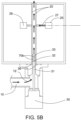
- FIG. 5B demonstrates an illustrative example of a system that incorporates lossy surface 70b into its design.
- FIG. 6 is a plot of obstruction of light transference media in the form of particulate deposition onto flow cells.
- Two light transference media (flow cells for this Example) were used to perform the experiment: ultrasonic energy was applied to the test flow cell, and no cleaning method was implemented for the control flow cell.
- the flow cells were initially clean and of the same type.
- the flow cells were exposed to the same blowdown stream of a 1500 psi recovery boiler of a paper mill.
- the flow cells were quartz glass tubes, each having an outer diameter of 0.312" (7.9 mm), an inner diameter of 0.236" (6 mm), and a length of 4.69" (11.9 cm).
- the ultrasonic energy was applied via a probe positioned at a distance (d) of 58 mm according to FIG.
- the blowdown of the recovery boiler flowed through the flow cells after being conditioned from saturated, e.g., 1515 psi (10445.56 kPa) at 597°F (313.89 °C), to less than 40 psi and less than 120°F.
- saturated e.g., 1515 psi (10445.56 kPa) at 597°F (313.89 °C)
- the conditioned blowdown is expected to flow through the flow cells under laminar flow, as the flow rate is approximately 500 mL/min and having a Reynolds Number of approximately 1800.
- the experiment was carried out over 20 days for the control flow cell, which continued to accumulate particulate deposition up to about 75% obstruction.
- the experiment was carried out over 14 days for the test flow cell, which accumulated virtually no obstruction over the 14-day trial. Obstruction of the light transference medium was virtually eliminated by the application of ultrasonic energy at a frequency of 40 kHz.
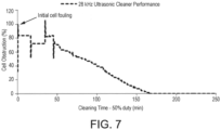
- FIG. 7 is a plot of particulate deposition being removed from a light transference medium, in this instance a flow cell, over time by the application of ultrasonic energy to the flow cell.
- the flow cell was exposed to a blowdown stream of a powerhouse boiler.
- the flow cell was approximately 100% obstructed at the beginning of the experiment. Blowdown of the powerhouse boiler flowed through the flow cell at 300 mL/min after being conditioned as in Example 1 herein.
- FIG. 8 is a plot of the effect of the utilization of an enhancer in combination with an EPDM washer used to seal the ultrasonic energy source to a light transference medium, for this Example flow cells as described in Examples 1 and 2 herein.
- Each EPDM washer used to seal the flow cells had a Shore "A" hardness of 55 to 75.
- the enhancer was a sleeve covering the EPDM washer and part of the light transference medium of the test flow cell.
- the control flow cell incorporated the EPDM washer seal but did not incorporate an enhancer.
- each of the two flow cells were initially 100% obstructed by particulate deposition and were exposed to the same conditioned blowdown stream as in Examples 1 and 2, except that the preconditioned blowdown stream was initially saturated at 700 psi (4826.33 kPa) and 503 °F (261.67 °C).
- the conditioned blowdown stream (less than 40 psig and less than 120°F) flowed through the flow cells at approximately 300 mL/min.
- Ultrasonic energy was applied to both the control flow cell and the test flow cell.
- the distance (d) was 56 mm and offset (X) was 6 mm, as shown in FIG. 2 , which falls within the parameters of Formula 3.
- incorporation of the enhancer of the test flow cell was clearly beneficial in minimizing the dampening effect of the EPDM washer.
- the sleeve was constructed of 316-stainless steel "thin wall" tubing, having an outer diameter slightly less than the 0.236" inner diameter of the test flow cell.
- the ultrasonic energy was applied to each flow cell at 20 kHz, which was intermittently applied at 50% duty. As shown in FIG. 8 , the control sample showed little removal of obstruction at 20 kHz at 50% duty for the 2000-minute test. However, utilization of a sleeve covering the EPDM washer and a portion of the test flow cell allowed for nearly complete removal of the obstruction after about 1000 minutes of 20 kHz ultrasonic energy at 50% duty.
Landscapes
- Physics & Mathematics (AREA)
- General Physics & Mathematics (AREA)
- Nonlinear Science (AREA)
- Immunology (AREA)
- Health & Medical Sciences (AREA)
- Biochemistry (AREA)
- General Health & Medical Sciences (AREA)
- Chemical & Material Sciences (AREA)
- Life Sciences & Earth Sciences (AREA)
- Pathology (AREA)
- Analytical Chemistry (AREA)
- Optics & Photonics (AREA)
- Engineering & Computer Science (AREA)
- Mechanical Engineering (AREA)
- Physical Or Chemical Processes And Apparatus (AREA)
- Physical Water Treatments (AREA)
- Organic Low-Molecular-Weight Compounds And Preparation Thereof (AREA)
Description
- Measurement of parameters in liquids using optical sensors is commonplace. Reliable measurement of such parameters generally requires light to pass into the liquid, which generally requires light to first pass through a reasonably transparent medium, e.g., a light transference medium. Reliability issues can arise in the event of obstruction of optical transference through the medium, which may be caused by particulate matter.
- Generally, boiler liquids are deaerated liquids that have unique features. Some unique features of boiler liquids include having very low levels of dissolved oxygen (e.g., less than 10 ppb dissolved oxygen in conventional boiler feedwater) and having a pH ranging from 9 to 11. Particularly in boiler systems utilizing a form of treatment control based on light detection and/or measurement (e.g., fluorometry), some amount of corrosion will occur over time and deposit in the form of particulate matter onto a light transference medium, thereby causing some amount of optical obstruction of the light transference medium. Regarding detection and measurement methods that utilize light transference, the unique conditions of deaerated liquids, particularly boiler liquid, present a challenge to the user when a light transference medium becomes optically obstructed. Ideally, optical obstruction can be altogether prevented, and if optical obstruction occurs, it can be removed without disrupting detection, measurement, and/or treatment control via the light transference.
-
WO2014/060023 A1 discloses a method for ultrasonic cavitation cleaning of an optical window in an analysis system in a process line containing process liquid, the method including subjecting the window to ultrasonic signals. -
US6324900 B1 discloses a method for optically measuring the transparency of a liquid by means of a turbidity analyser, wherein ultrasound waves are generated in all directions around the emitting and receiving optical/liquid interfaces in contact with the liquid, thereby cleaning the interface surfaces.US2009/032733 A1 discloses an apparatus, for measuring the amount of a material present in a liquid, comprising a measurement chamber with an optical window for transmitting both excitation light to the liquid and fluorescent light to a detector. An ultrasonic transducer for cleaning the optical window is coupled to the measurement chamber. - A method of obtaining, or of maintaining, optical transference into deaerated liquid in contact with a light transference medium is provided. The method comprises applying ultrasonic energy at a wavelength (λ) into deaerated liquid in contact with a light transference medium. The ultrasonic energy at wavelength (λ) originates at a distance (d) from an optical signal transmitted into the light transference medium such that optical transference into the deaerated liquid via the light transference medium is obtained or maintained.
-
-
FIG. 1 illustrates an embodiment of a system capable of performing at least one inventive method described herein; -
FIG. 2 illustrates a variation of the illustrative embodiment shown inFIG. 1 ; -
FIG. 3 illustrates an embodiment of a system capable of performing at least one inventive method described herein; -
FIG. 4 illustrates an embodiment of a system capable of performing at least one inventive method described herein; -
FIG. 5A illustrates an embodiment of a system incorporating a sleeve as described herein; -
FIG. 5B illustrates an embodiment of a system incorporating a lossy surface; -
FIG. 6 is a plot of experimental data collected during the execution of Example 1; -
FIG. 7 is a plot of experimental data collected during the execution of Example 2; and -
FIG. 8 is a plot of experimental data collected during the execution of Example 3. - While embodiments encompassing the general inventive concepts may take various forms, there is shown in the drawings and will hereinafter be described various illustrative and preferred embodiments with the understanding that the present disclosure is to be considered an exemplification.
- A method of maintaining optical transference into deaerated (e.g., degassed) liquid in contact with a light transference medium according to the invention is defined in independent claim 1. In certain embodiments, liquid is deaerated prior to being utilized in a heating application (e.g., a boiler). Liquid is generally deaerated in an attempt to minimize corrosion of metals that come in contact with the steam and/or liquid. Illustrative deaerated liquids include, but are not limited to, deaerated boiler make-up feedwater and boiler liquid, which further includes boiler blowdown liquid and boiler condensate liquid. The phrase "deaeratedboiler make-up feedwater" is used to describe the boiler make-up feedwater that has undergone a deaeration process. The term is not used to describe the various boiler liquids, as it is understood by those skilled in the art that boiler liquids have already undergone a deaeration process prior to becoming boiler liquid.
- As it pertains to this disclosure, unless otherwise indicated, "controller" refers to an electronic device having components such as a processor, memory device, digital storage medium, cathode ray tube, liquid crystal display, plasma display, touch screen, or other monitor, and/or other components. Controllers include, for example, an interactive interface that guides a user, provides prompts to the user, or provides information to the user regarding any portion of the method of the invention. Such information may include, for example, building of calibration models, data collection of one or more parameters, measurement location(s), management of resulting data sets, etc.
- The controller is preferably operable for integration and/or communication with one or more application-specific integrated circuits, programs, computer-executable instructions or algorithms, one or more hard-wired devices, wireless devices, and/or one or more mechanical devices such as liquid handlers, hydraulic arms, servos, or other devices. Moreover, the controller is operable to integrate feedback, feed-forward, or predictive loop(s) resulting from, inter alia, the parameters measured by practicing the method(s) of the present disclosure. Some or all of the controller system functions may be at a central location, such as a network server, for communication over a local area network, wide area network, wireless network, extranet, the Internet, microwave link, infrared link, and the like, and any combinations of such links or other suitable links. In addition, other components such as a signal conditioner or system monitor may be included to facilitate signal transmission and signal-processing algorithms.
- By way of example, the controller is operable to implement the method of the invention in a semi-automated or fully-automated fashion. In another embodiment, the controller is operable to implement the method in a manual or semi-manual fashion.
- Data transmission of any of the measured parameters or signals to a user, chemical pumps, alarms, or other system components is accomplished using any suitable device, such as a wired or wireless network, cable, digital subscriber line, internet, etc. Any suitable interface standard(s), such as an ethernet interface, wireless interface (e.g., IEEE 802.lla/b/g/n, 802.16, Bluetooth, optical, infrared, other radiofrequency, any other suitable wireless data transmission method, and any combinations of the foregoing), universal serial bus, telephone network, the like, and combinations of such interfaces/connections may be used. As used herein, the term "network" encompasses all of these data transmission methods. Any of the components, devices, sensors, etc., herein described may be connected to one another and/or the controller using the above-described or other suitable interface or connection. In an embodiment, information (collectively referring to all of the inputs or outputs generated by the method of the invention) is received from the system and archived. In another embodiment, such information is processed according to a timetable or schedule. In a further embodiment, such information is processed in real-time. Such real-time reception may also include, for example, "streaming data" over a computer network.
- As it pertains to this disclosure, unless otherwise indicated, "control scheme" refers to providing output based on input from a controller as defined herein.
- In the method according to the invention, the ultrasonic energy at wavelength (λ) originates at a distance (d) from an optical signal transmitted into the light transference medium so as to obtain or maintain optical transference into the deaerated liquid via the light transference medium, and the distance (d) is defined by Formula 1 below:

- Ultrasonic energy follows the laws of acoustics. If the speed (v) of the ultrasonic energy is known, or approximately known, wavelength (λ) can be defined by frequency (f) according to Formula 2 below:

- The terms "optical" and "light" are used interchangeably herein. Utilization of the phrase "into deaerated liquid" is intended to cover light transmission in any direction between the deaerated liquid, the light transference medium, a light source, and/or a light detector. For example, the optical signal may originate from within the deaerated liquid and be transferred to a sensor via the light transference medium (e.g., fluorometric emission), or from a light source through the light transference medium and into the deaerated liquid (e.g., fluorometric excitation). Illustrative examples of optical sensors that perform optical measurements using optical signals include, but are not limited to, devices capable of detecting or sensing absorbance, colorimetric, refractometric, spectrophotometric, luminometric, and/or fluorometric signals, or images. In one example, the optical signal comprises a fluorometric excitation and/or emission.
- The method is directed to obtaining or maintaining optical transference into deaerated liquid in contact with a light transference medium. The method can be utilized to remove obstructions that may be present on the light transference medium. Removal of obstruction from the light transference medium sufficient to allow for optical transference, thereby allowing for performance of an optical measurement of the deaerated liquid, is also achieved by the method of the present invention.
- An advantage of the present invention is that the method can be performed without interrupting the process responsible for supplying the deaerated liquid. For example, a boiler and its related treatment processes can continue to operate during performance of the method described herein.
- Ultrasonic energy is applied into deaerated liquid in contact with a light transference medium. The ultrasonic energy is applied to effectuate removal of optical obstruction that may be present on the light transference medium, particularly at a location of the light transference medium where an optical signal passes through, or should pass through.
- In preferred embodiments, the deaerated liquid in contact with the light transference medium is flowing across the light transference medium as defined herein.
- In embodiments where the deaerated liquid flows across the light transference medium, the liquid may do so under conditions described as laminar, turbulent, and/or transitional flow. The deaerated liquid may have a Reynolds number ranging from 0 to 4000, including from 400 to 3000 or from 800 to 2300
- For embodiments where the deaerated liquid is flowing across the light transference medium, the ultrasonic energy may originate upstream or downstream from a location of a light transference medium where an optical signal passes through, or should pass through. In a preferred embodiment, the ultrasonic energy originates upstream from a location of a light transference medium where an optical signal passes through, or should pass through.
- The ultrasonic energy may have a frequency ranging from 20 kHz to 200 kHz. In some embodiments, the ultrasonic energy has a frequency ranging from 20 kHz to 80 kHz. In further embodiments, the ultrasonic energy has a frequency ranging from 30 kHz to 60 kHz, which includes 40 kHz. In even further embodiments, the ultrasonic energy has a frequency ranging from 25 kHz to 30 kHz, which includes 28 kHz.
- In certain embodiments, the ultrasonic energy is applied at a rate of from 1 W/cm2/sec to 400 W/cm2/sec. The ultrasonic energy may be applied at a rate of from 1 W/cm2/sec, or from 10 W/cm2/sec, or from 50 W/cm2/sec, or from 100 W/cm2/sec, to 400 W/cm2/sec, or to 300 W/cm2/sec, or to 200 W/cm2/sec.
- The wavelength of the ultrasonic energy is dependent upon the frequency and the velocity of the ultrasonic energy, which is essentially constant. The frequency, and therefore the wavelength, is chosen so as to provide enough energy to prevent or remove particulate matter that may become deposited onto a light transference medium in contact with deaerated liquid. Ideally, the frequency of the ultrasonic energy will be sufficient to remove such particulate matter, or prevent the particulate matter from depositing onto the light transference medium, while not damaging the light transference medium. However, a user may attempt to minimize or prevent damage to the light transference medium by utilizing one or more of several modifications discussed herein.
- As described herein, the ultrasonic energy originates at a distance (d) from an optical signal transmitted into the light transference medium, which is preferably set to optimize the energy applied into the deaerated liquid at a point relative to the light transference medium, to effectively obtain or maintain light transference. The distance (d) is defined by Formula 1 herein. For example, in embodiments that apply ultrasonic energy using an ultrasonic probe, the tip of the ultrasonic probe is located at a distance (d) such that particulate matter deposited onto the light transference medium becomes dislodged, thereby maintaining optical transference into the deaerated liquid in contact with the light transference medium. The distance (d) within certain ranges defined herein, is thereby causing the ultrasonic energy to "originate" from the distance (d).
- In certain examples, the ultrasonic energy originates at a distance of from 30% to 70%, or from 35 % to 65 %, or from 40% to 60%, of the wavelength of the ultrasonic energy. In other examples, the ultrasonic energy originates at a distance from an optical signal transmitted into the light transference medium of from 80% to 120%, or from 85% to about 115%, or from 90% to 110%, of the wavelength of the ultrasonic energy. In certain examples, the ultrasonic energy originates at a distance of from 130% to 170%, or from 135% to 165%, or from 140% to 160%, of the wavelength of the ultrasonic energy. In other examples, the ultrasonic energy originates at a distance from an optical signal transmitted into the light transference medium of from 180% to 220%, or from 185% to 215%, or from 190% to 210%, of the wavelength of the ultrasonic energy. In certain examples, the ultrasonic energy originates at a distance of from 230% to 270%, or from 235% to 265%, or from 240% to 260%, of the wavelength of the ultrasonic energy. In other examples, the ultrasonic energy originates at a distance from an optical signal transmitted into the light transference medium of from 280% to 320%, or from 285% to 315%, or from 290% to 310%, of the wavelength of the ultrasonic energy. In certain examples, the ultrasonic energy originates at a distance of from 330% to 370%, or from 335% to 365%, or from 40% to 360%, of the wavelength of the ultrasonic energy. In other examples, the ultrasonic energy originates at a distance from an optical signal transmitted into the light transference medium of from 380% to 420%, or from 385% to 415%, or from 390% to 410%, of the wavelength of the ultrasonic energy. In certain examples, the ultrasonic energy originates at a distance of from 430% to 470%, or from 435% to 465%, or from 440% to 460%, of the wavelength of the ultrasonic energy. In other examples, the ultrasonic energy originates at a distance from an optical signal transmitted into the light transference medium of from 480% to 520%, or from 485% to 515%, or from 490% to 510%, of the wavelength of the ultrasonic energy.
- In certain embodiments, a parameter of the deaerated liquid in contact with the light transference medium is measured by transmitting the optical signal into the deaerated liquid via the light transference medium, and detecting a response. In certain examples, the parameter is fluorescence, light absorbance, temperature, chemiluminescence, optical scattering (e.g., Rayleigh, Mie, and Raman scatter), imaging, transmittance, particle size, particle count, or turbidity, or any combination thereof.
- In certain examples, the method is a clean-in-place method. A clean-in-place method does not require disassembly of the system in order to conduct the method. In other words, the light transference medium is not removed from the system, and the system is not disconnected for the purpose of accessing the light transference medium.
- In certain examples, treatment of the deaerated liquid is controlled by utilizing the measured parameter in a control scheme. Treatment of the deaerated liquid may include, but is not limited to, at least one of physical treatment and chemical treatment. Non-limiting examples of physical treatment include adjustment of any of the following parameters of the deaerated liquid: temperature, pressure, physical phase, flow rate (e.g., circulation, blowdown, and/or make-up), flow path, and mixing. Non-limiting examples of chemical treatment include adjustment of any of the following parameters, all related to a treatment chemical: chemical species selection, chemical species concentration, chemical species dosage rate, chemical species dosage location, and deaeration completeness.
- In certain examples, the measured parameter is inputted into a control scheme. The control scheme is generally an automated method that inputs a plurality of several measured parameters and operates several process devices, e.g., pumps, valves, etc. For example, a certain measured parameter may indicate that treatment chemical concentration has fallen outside a lower tolerance limit. For the present example, the measured parameter may trigger the control scheme to operate a feed pump, which in turn adds treatment chemical to the process.
- In certain embodiments, the optical transference through the light transference medium is at least partially obstructed by particulate matter or scaling. In some embodiments, the particulate matter may comprise a metal oxide. In certain embodiments, the light transference medium is obstructed by deposition of a chemical species comprising iron, copper, manganese, titanium, chromium, nickel, calcium, magnesium, oxide, phosphate, carbonate, or silicate, or any combination thereof. In certain embodiments, the light transference medium is obstructed by scale comprising calcium, magnesium, phosphate, carbonate, or silicate, or any combination thereof.
- In other embodiments, the particulate deposition may comprise particulate matter found in raw water, e.g., mud, sand, silt, etc.
- In certain embodiments, the deaerated liquid may be conditioned prior to contacting the light transference medium. For example, particularly when the deaerated liquid is boiler blowdown liquid or boiler condensate liquid, the deaerated liquid may be "enthalpy-rich." At elevated temperature and pressure the deaerated liquid may be conditioned such that a portion of the enthalpy (measured in the form of temperature and pressure) are removed prior to the deaerated liquid contacting the light transference medium. In certain embodiments, the deaerated liquid in contact with the light transference medium has a temperature of from -6.6 °C to 93.3 °C, corresponding to 20°F to 200°F, including from 40°F to 150°F, and including from 60°F to 130°F. In certain embodiments, the deaerated liquid in contact with the light transference medium has a pressure of from 34.47 kPa to 689.48 kPa, corresponding to from 5 to 100 psi, including from 10 psi to 70 psi, and including from 15 psi to 50 psi.
- The timing of the application of the ultrasonic energy to the deaerated liquid may take any one or more of several forms. In one example, the ultrasonic energy is continuously streamed into the deaerated liquid, which preferably includes while the system utilizing the deaerated liquid is operational. In another example, the ultrasonic energy is applied intermittently, e.g., for a timed duration at timed intervals. In yet another example, the ultrasonic energy is applied on an as-needed basis, which can be determined, e.g., by comparing historical data related to the relevant sensor and light transference medium. For example, if obstruction of the light transference medium grows to an unacceptable value, e.g., a setpoint of from 1 to 5% obstruction, ultrasonic energy is then applied to the wetted surface of the light transference medium as described herein.
- Examples of light transference media include a flow cell, an optical window, a reflective surface, a refractive surface, a dispersive element, a filtering element, and an optical fiber sensor head. In embodiments where the light transference medium is transparent or nearly transparent, the light transference medium is generally constructed of a material that is transparent or nearly transparent and having a hardness of at least about 7 on the Mohs scale. The term "transparent or nearly transparent" refers to the ability of light to pass through a substance sufficient to use light for detection and/or measurement purposes as discussed herein, which includes transparency as defined by ASTM D1746. In certain embodiments, the light transference medium is constructed of quartz, sapphire, diamond, or boron nitride.
- In certain embodiments, the light transference medium is constructed of any suitable transparent or nearly transparent composition, and is coated with a transparent or nearly transparent substance having a hardness of at least about 7 on the Mohs scale. For example, the light transference medium may be constructed of a substance having a Mohs scale hardness of at least about 7 (e.g., quartz), and then coated with a substance having an even higher Mohs scale rating. In certain embodiments, the coating substance has a Mohs scale rating of from 8 to 10, or from 9 to 10, or 10. Illustrative examples of substances suitable for coating a light transference medium include, but are not limited to, diamond, titanium diboride, boron nitride, and sapphire.
- In certain examples, the light transference medium takes the form of a reflective surface. In examples utilizing a reflective surface, an optical window may be utilized in concert with the reflective surface to provide observation from outside the deaerated liquid.
-
FIG. 1 illustrates a system capable of performing the inventive method. Adeaerated liquid 10, which flows in adirection 12, contacts alight transference medium 20.Light transference medium 20 is a flow cell, and deaerated liquid 10 flows through the flow cell viadirection 12. Alight source 25 and adetector 26 are located so as to transmit anoptical signal 27 throughlight transference medium 20 and deaerated liquid 10, and detect the resulting behavior caused by the transmittedoptical signal 27, which may include fluorescence, light absorbance, temperature, chemiluminescence, optical scattering (e.g., Rayleigh, Mie, and Raman scatter), imaging, transmittance, particle size, particle count, turbidity, and combinations thereof. Anultrasonic transducer 30 is operably attached to anultrasonic probe 31 having atip 32 that emitsultrasonic energy 33 at a wavelength (λ), withtip 32 being located at a distance (d) from theoptical signal 27, with distance (d) being defined by Formula 1 presented herein. Optionally, theultrasonic probe 31 may be positioned such thattip 32 emitsultrasonic energy 33 at an angle α of from 0 to about 45 degrees, or to about 35 degrees, or to about 25 degrees, or to about 15 degrees, or to about 5 degrees, as illustrated. In certain examples, theultrasonic probe 31 is positioned such thattip 32 projectsultrasonic energy 33 substantially in the direction offlow 12 of deaerated liquid 10 acrosslight transference medium 20.FIGs. 1 ,2 ,4 ,5A , and5B illustrate examples including a mount that sealsultrasonic transducer 30 tolight transference medium 20 utilizing aseal 36, which in certain examples is a washer. In certain examples,seal 36 is constructed of an elastomer. Examples of elastomers include, but are not limited to, nitrile-butadiene rubber ("nitrile"), hydrogenated nitrile-butadiene rubber, ethylene propylene diene monomer ("EPDM"), silicone, fluoroelastomer, and polychloroprene. -
FIG. 2 illustrates an example, wherein thetip 32 of theultrasonic probe 31 is positioned so as to create an offset X fromlight transference medium 20. Utilization of offset X can be of particular importance to allow sufficient ultrasonic energy at wavelength (λ) into the light transference medium when a relatively soft material (e.g., seal 36) is present in the direction of the ultrasonic energy. The ultrasonic energy will be less likely to be dampened by the relatively soft material due to the low energy level at the location of the relatively soft material. In examples that incorporate a relatively soft material between anultrasonic probe 31 and alight transference medium 20, the distance (d) should be measured from a point beyond the relatively soft material tolight transference medium 20, as illustrated inFIG. 2 . In certain examples utilizing offset X, offset X is defined byFormula 3 below:
-
FIG. 3 illustrates yet another example of a system capable of performing the inventive method. Adeaerated liquid 10, which flows in adirection 12, contacts alight transference medium 20, which can be, for example, mounted via a tee pipe fitting 100.Light transference medium 20 takes the form of an optical window of a combination light source/detector 25/26, and deaerated liquid 10 flows across the optical window. Combination light source/detector 25/26 is located so as to transmit anoptical signal 27 through light transference medium 20 (the optical window) and into the deaerated liquid 10, and detect the resulting behavior caused byoptical signal 27, which may include fluorescence, light absorbance, temperature, chemiluminescence, optical scattering (e.g., Rayleigh, Mie, and Raman scatter), imaging, transmittance, particle size, particle count, turbidity, and combinations thereof. WhileFIG. 3 shows an example utilizing a combination light source/detector 25/26, a person skilled in the art will readily recognize that the light source and the detector may be separate units operably connected to a control unit (not shown). Anultrasonic transducer 30 is operably attached to anultrasonic probe 31 having atip 32 that emitsultrasonic energy 33, withtip 32 being located at a distance (d) from theoptical signal 27, with distance (d) defined by Formula 1 presented herein. -
FIG. 4 illustrates a further example of a system capable of performing the inventive method is illustrated. Adeaerated liquid 10, which may flow in adirection 12, contacts alight transference medium 20.Light transference medium 20 includes atransparent portion 20a and an optionalreflective portion 20b, and deaerated liquid 10 contacts each oftransparent portion 20a andreflective portion 20b. A combination light source/detector 25/26 is located so as to transmit anoptical signal 27 throughtransparent portion 20a and into deaerated liquid 10, and detect the resulting behavior caused byoptical signal 27, which may include fluorescence, light absorbance, temperature, chemiluminescence, optical scattering (e.g., Rayleigh, Mie, and Raman scatter), imaging, transmittance, particle size, particle count, turbidity, and combinations thereof.Optical signal 27 may be transmitted from combination light source/detector 25/26 via optical fibers capable of receiving and transmitting fluorescent emission to the combination light source/detector 25/26. Alternately, the system may be configured to utilize alight source 25 anddetector 26 in addition to or in place of the combination light source/detector 25/26, whereinlight source 25 anddetector 26 are not aligned opposite one another. While a combination light source/detector 25/26 is illustrated in this particular example, a person of skill in the art will readily recognize that the light source and the detector may be separate units connected to a control unit (not shown). Anultrasonic transducer 30 is operably attached to anultrasonic probe 31 having atip 32 that emitsultrasonic energy 33, withtip 32 located at a distance (d) fromoptical signal 27, with distance (d) being defined by Formula 1 presented herein. - In certain examples, an enhancer is utilized to assist in performing the methods described herein. When utilized, the enhancer allows ultrasonic energy to be applied in a manner that provides beneficial removal of obstruction while protecting the light transference medium from damage that may be caused by the application of ultrasonic energy. Particularly when applied at sharp angles (e.g., perpendicular) toward the light transference medium, ultrasonic energy can damage the light transference medium. The utilization of one or more enhancers can limit or prevent the occurrence of such damage. When utilized, the enhancer may comprise at least one of a sleeve and a lossy surface. It is important to note that these particular enhancers may be used individually or in combination, or not used at all. Whether to use an enhancer depends on a number of factors, including, but not limited to, the durability of the light transference medium, and the angle and frequency of the ultrasonic energy.
- In examples utilizing a sleeve as an enhancer, the sleeve is generally positioned so as to protect a portion of the light transference medium located near the source of ultrasonic energy. Generally, the sleeve is constructed and positioned so as to prevent dampening of the ultrasonic energy in the vicinity of the transmission of the optical signal into the light transference medium. More particularly, the sleeve should protect the light transference medium from damage that may be caused by ultrasonic energy traveling perpendicular or nearly perpendicular from the ultrasonic energy source toward the light transference medium. When utilized, the sleeve should be constructed of a material suitable for providing protection to the light transference medium. For example, the sleeve may be constructed of stainless steel.
- In other examples, the sleeve is constructed of a substance that is not completely rigid, but is not so soft as to absorb an undesired amount of the ultrasonic energy. For example, when utilizing a sleeve, the sleeve may be constructed of a substance compatible with contacting liquid(s). Furthermore, the sleeve may be constructed of a substance having a Shore "A" hardness of from about 60 to about 90. In certain embodiments, the sleeve is constructed of an elastomer as defined herein.
FIG. 5A demonstrates an illustrative example of a system that incorporatessleeve 70a into its design. Example 3 provides further information related to an example of a sleeve utilized to prevent over-dampening. - In examples utilizing a lossy surface as an enhancer, the lossy surface is generally positioned so as to protect a portion of the light transference medium located near the source of ultrasonic energy. Generally, the lossy surface is positioned so as to dampen a portion of the ultrasonic energy traveling toward the light transference medium, and particularly the ultrasonic energy traveling perpendicular or nearly perpendicular from the ultrasonic energy source toward the light transference medium. In certain examples, the lossy surface is a surface that is generally rough, such as, e.g., a grooved, threaded, or jagged surface. Generally, a lossy surface is rough such that at least a portion of the ultrasonic energy is scattered away when coming in contact with the lossy surface.
FIG. 5B demonstrates an illustrative example of a system that incorporateslossy surface 70b into its design. - The following examples further illustrate the invention but, of course, should not be construed as in any way limiting its scope, which is defined by the appended claims.
-
FIG. 6 is a plot of obstruction of light transference media in the form of particulate deposition onto flow cells. Two light transference media (flow cells for this Example) were used to perform the experiment: ultrasonic energy was applied to the test flow cell, and no cleaning method was implemented for the control flow cell. In the example, the flow cells were initially clean and of the same type. The flow cells were exposed to the same blowdown stream of a 1500 psi recovery boiler of a paper mill. The flow cells were quartz glass tubes, each having an outer diameter of 0.312" (7.9 mm), an inner diameter of 0.236" (6 mm), and a length of 4.69" (11.9 cm). The ultrasonic energy was applied via a probe positioned at a distance (d) of 58 mm according toFIG. 1 and Formula 1 (i.e., n = 3), with the tip of the ultrasonic probe positioned flush with the end of the light transference medium. The blowdown of the recovery boiler flowed through the flow cells after being conditioned from saturated, e.g., 1515 psi (10445.56 kPa) at 597°F (313.89 °C), to less than 40 psi and less than 120°F. The conditioned blowdown is expected to flow through the flow cells under laminar flow, as the flow rate is approximately 500 mL/min and having a Reynolds Number of approximately 1800. - Ultrasonic energy was applied to the test flow cell at 40 kHz, which was intermittently applied at 2.2% duty. In other words, the ultrasonic energy was applied to the test flow cell for 1 minute per 45 minutes (i.e., 1 minute / 45 minutes = 0.022).
- The experiment was carried out over 20 days for the control flow cell, which continued to accumulate particulate deposition up to about 75% obstruction. The experiment was carried out over 14 days for the test flow cell, which accumulated virtually no obstruction over the 14-day trial. Obstruction of the light transference medium was virtually eliminated by the application of ultrasonic energy at a frequency of 40 kHz.
-
FIG. 7 is a plot of particulate deposition being removed from a light transference medium, in this instance a flow cell, over time by the application of ultrasonic energy to the flow cell. In the example, the flow cell was exposed to a blowdown stream of a powerhouse boiler. The flow cell was the same as the test flow cell of Example 1 herein, except that the distance (d) was 56 mm, and the tip of the ultrasonic probe was 10 mm beyond the end of the flow cell (offset (X) = 10 mm) as shown inFIG. 2 . Offset (X) fitsFormula 3, with n = 1. The flow cell was approximately 100% obstructed at the beginning of the experiment. Blowdown of the powerhouse boiler flowed through the flow cell at 300 mL/min after being conditioned as in Example 1 herein. - Ultrasonic energy was applied to the flow cell at 28 kHz, which was intermittently applied at 50% duty (i.e., one minute "on" for every minute "off"), as opposed to the 2.2% duty to the test flow cell of Example 1. The experiment was carried out over approximately 250 minutes. By approximately the 170th minute, substantially all of the particulate deposition had been removed, and the flow cell was substantially unobstructed.
-
FIG. 8 is a plot of the effect of the utilization of an enhancer in combination with an EPDM washer used to seal the ultrasonic energy source to a light transference medium, for this Example flow cells as described in Examples 1 and 2 herein. Each EPDM washer used to seal the flow cells had a Shore "A" hardness of 55 to 75. For this Example, the enhancer was a sleeve covering the EPDM washer and part of the light transference medium of the test flow cell. The control flow cell incorporated the EPDM washer seal but did not incorporate an enhancer. In the example, each of the two flow cells were initially 100% obstructed by particulate deposition and were exposed to the same conditioned blowdown stream as in Examples 1 and 2, except that the preconditioned blowdown stream was initially saturated at 700 psi (4826.33 kPa) and 503 °F (261.67 °C). The conditioned blowdown stream (less than 40 psig and less than 120°F) flowed through the flow cells at approximately 300 mL/min. Ultrasonic energy was applied to both the control flow cell and the test flow cell. The distance (d) for the test flow cell was 62 mm, and the tip of the ultrasonic probe was 6 mm beyond each flow cell (offset (X) = 6 mm, but only for the control flow cell). Because the EPDM washer was covered by an enhancer for the test flow cell, the distance (d) followedFIG. 1 and Formula 1, with n = 2. For the control flow cell, the distance (d) was 56 mm and offset (X) was 6 mm, as shown inFIG. 2 , which falls within the parameters ofFormula 3. However, incorporation of the enhancer of the test flow cell was clearly beneficial in minimizing the dampening effect of the EPDM washer. - The sleeve was constructed of 316-stainless steel "thin wall" tubing, having an outer diameter slightly less than the 0.236" inner diameter of the test flow cell. The ultrasonic energy was applied to each flow cell at 20 kHz, which was intermittently applied at 50% duty. As shown in
FIG. 8 , the control sample showed little removal of obstruction at 20 kHz at 50% duty for the 2000-minute test. However, utilization of a sleeve covering the EPDM washer and a portion of the test flow cell allowed for nearly complete removal of the obstruction after about 1000 minutes of 20 kHz ultrasonic energy at 50% duty. - The use of the terms "a" and "an" and "the" and "at least one" and similar referents in the context of describing the invention (especially in the context of the following claims) are to be construed to cover both the singular and the plural, unless otherwise indicated herein or clearly contradicted by context. The use of the term "at least one" followed by a list of one or more items (for example, "at least one of A and B") is to be construed to mean one item selected from the listed items (A or B) or any combination of two or more of the listed items (A and B), unless otherwise indicated herein or clearly contradicted by context. The terms "comprising," "having," "including," and "containing" are to be construed as open-ended terms (i.e., meaning "including, but not limited to,") unless otherwise noted. Recitation of ranges of values herein are merely intended to serve as a shorthand method of referring individually to each separate value falling within the range, unless otherwise indicated herein. All methods described herein can be performed in any suitable order unless otherwise indicated herein or otherwise clearly contradicted by context. The use of any and all examples, or exemplary language (e.g., "such as," "illustrative") provided herein, is intended merely to better describe the invention .
- Preferred embodiments of this invention are described herein, including the best mode known to the inventors for carrying out the invention. Variations of those preferred embodiments may become apparent to those of ordinary skill in the art upon reading the foregoing description. The inventors expect skilled artisans to employ such variations as appropriate, and the inventors intend for the invention to be practiced otherwise than as specifically described herein. Accordingly, this invention includes all modifications and equivalents of the subject matter recited in the claims appended hereto.
Claims (15)
- A method of obtaining or maintaining optical transference of an optical signal into deaerated liquid (10) in contact with a light transference medium (20), wherein the liquid (10) flows in a direction (12), and contacts the optical transference medium (20), the method comprising: applying ultrasonic energy (33) at a wavelength (λ) into the deaerated liquid in contact with the light transference medium to obtain or maintain optical transference of the optical signal, the ultrasonic energy at wavelength (λ) originating at a distance (d) in the deaerated liquid (10) from the optical signal (27) transmitted from the light transference medium into the liquid, wherein the distance (d) is defined by the formula:

- The method of claim 1, wherein the constant a is in the range from -0.15 to 0.15, or in the range from -0.1 to 0.1.
- The method of any one of claims 1 or 2, further comprising measuring a parameter of the deaerated liquid in contact with the light transference medium by transmitting the optical signal into the deaerated liquid via the light transference medium, and detecting a response.
- The method of any one of claims 1 to 3, wherein the method is performed during operation of a system utilizing the deaerated liquid.
- The method of any one of claims 1 to 4, wherein the optical transference through the light transference medium is obstructed prior to the application of the ultrasonic energy to the light transference medium.
- The method of any one of claims 1 to 5, wherein the deaerated liquid is at least one of deaerated boiler make-up feedwater, boiler condensate and boiler blowdown liquid.
- The method of any one of claims 1 to 6, wherein the light transference medium is obstructed by deposition of a chemical species selected from the group consisting of iron, copper, manganese, titanium, chromium, nickel, calcium, magnesium, oxide, phosphate, carbonate, silicate and combinations thereof.
- The method of any one of claims 1 to 7, wherein the light transference medium is obstructed by scale comprising a chemical species selected from the group consisting of calcium, magnesium, phosphate, carbonate, silicate and combinations thereof.
- The method of any one of claims 1 to 8, wherein the ultrasonic energy is applied at a rate of from 1 W/cm2/sec to 400 W/cm2/sec.
- The method of any one of claims 1 to 9, wherein the ultrasonic energy is applied at a frequency of from 20 kHz to 200 kHz.
- The method of any one of claims 1 to 10, wherein the light transference medium has a Mohs scale hardness of at least about 7.
- The method of any one of claims 1 to 11, wherein the light transference medium is constructed of a material selected from the group consisting of quartz, sapphire, diamond, boron nitride and derivatives thereof.
- The method of any one of claims 1 to 12, wherein the light transference medium is a quartz flow cell coated with at least one of diamond, titanium diboride, boron nitride and derivatives thereof.
- The method of any one of claims 1 to 13, wherein an enhancer protects at least a portion of the light transference medium from the ultrasonic energy source.
- The method of any one of claims 1 to 14, wherein the deaerated liquid contacts the light transference medium at a pressure of from 34.47 kPa (5 psi) to 689.48 kPa (100 psi), and at a temperature of from - 6.66 °C (20 °F) to 93.33 °C (200 °F).
Applications Claiming Priority (2)
| Application Number | Priority Date | Filing Date | Title |
|---|---|---|---|
| US14/592,219 US10197824B2 (en) | 2015-01-08 | 2015-01-08 | Method of obtaining or maintaining optical transmittance into deaerated liquid |
| PCT/US2016/012611 WO2016112264A1 (en) | 2015-01-08 | 2016-01-08 | Method of obtaining or maintaining optical transmittance into deaerated liquid |
Publications (4)
| Publication Number | Publication Date |
|---|---|
| EP3243071A1 EP3243071A1 (en) | 2017-11-15 |
| EP3243071A4 EP3243071A4 (en) | 2018-06-27 |
| EP3243071B1 true EP3243071B1 (en) | 2023-09-13 |
| EP3243071C0 EP3243071C0 (en) | 2023-09-13 |
Family
ID=56356460
Family Applications (1)
| Application Number | Title | Priority Date | Filing Date |
|---|---|---|---|
| EP16735460.4A Active EP3243071B1 (en) | 2015-01-08 | 2016-01-08 | Method of obtaining or maintaining optical transmittance into deaerated liquid |
Country Status (11)
| Country | Link |
|---|---|
| US (1) | US10197824B2 (en) |
| EP (1) | EP3243071B1 (en) |
| KR (1) | KR102477149B1 (en) |
| CN (1) | CN107430091B (en) |
| BR (1) | BR112017014860B1 (en) |
| CA (1) | CA2973095C (en) |
| CL (1) | CL2017001782A1 (en) |
| MX (1) | MX390564B (en) |
| SA (1) | SA517381878B1 (en) |
| SG (1) | SG11201705140SA (en) |
| WO (1) | WO2016112264A1 (en) |
Families Citing this family (2)
| Publication number | Priority date | Publication date | Assignee | Title |
|---|---|---|---|---|
| DE102017127855A1 (en) * | 2017-11-24 | 2019-05-29 | Echovista Gmbh | Optical monitoring device |
| US11733144B2 (en) * | 2020-12-14 | 2023-08-22 | Caterpillar Inc. | Convertible housing assembly for a particle sensor |
Family Cites Families (40)
| Publication number | Priority date | Publication date | Assignee | Title |
|---|---|---|---|---|
| US4307741A (en) | 1980-08-01 | 1981-12-29 | Bethlehem Steel Corporation | Probe cleaner |
| US4385936A (en) | 1980-08-01 | 1983-05-31 | Bethlehem Steel Corporation | Method for cleaning a process monitoring probe |
| US4890481A (en) * | 1986-02-17 | 1990-01-02 | Hitachi, Ltd. | System for measuring foreign materials in liquid |
| US5008906A (en) * | 1988-10-03 | 1991-04-16 | Armstrong World Industries, Inc. | Consistency measuring device for a slurry containing defoamer |
| US5185533A (en) | 1991-09-03 | 1993-02-09 | Nalco Chemical Company | Monitoring film fouling in a process stream with a transparent shunt and light detecting means |
| US5289838A (en) | 1991-12-27 | 1994-03-01 | The United States Of America As Represented By The United States Department Of Energy | Ultrasonic cleaning of interior surfaces |
| CH681747A5 (en) | 1992-06-02 | 1993-05-14 | Zuellig Ag | |
| US5918570A (en) * | 1997-11-05 | 1999-07-06 | Greenwich Hospital | Deaerated feedwater supply system for a boiler system and a method for deaerating boiler feedwater |
| US5889209A (en) | 1997-12-18 | 1999-03-30 | The Regents Of The University Of California | Method and apparatus for preventing biofouling of aquatic sensors |
| US6217937B1 (en) * | 1998-07-15 | 2001-04-17 | Cornell Research Foundation, Inc. | High throughput OMVPE apparatus |
| US6117084A (en) | 1998-11-17 | 2000-09-12 | Atl Ultrasound, Inc. | Ultrasonic probe connector enclosure |
| DE19917632A1 (en) | 1999-04-19 | 2000-10-26 | Gunther Krieg | Method and device for the automatic cleaning of optoelectronic sensor systems for substance analysis |
| US6572709B1 (en) | 1999-05-10 | 2003-06-03 | Dominion Engineering, Inc. | Ultrasonic cleaning method |
| EP1070953A1 (en) | 1999-07-21 | 2001-01-24 | Societe D'etude Et De Realisation D'equipements Speciaux - S.E.R.E.S. | Method and device for optically measuring liquid transparency |
| US6452672B1 (en) | 2000-03-10 | 2002-09-17 | Wyatt Technology Corporation | Self cleaning optical flow cell |
| US6336058B1 (en) | 2000-05-01 | 2002-01-01 | Nalco Chemical Company | Use of control matrix for boiler control |
| US6369894B1 (en) | 2000-05-01 | 2002-04-09 | Nalco Chemical Company | Modular fluorometer |
| US6315909B1 (en) | 2000-05-01 | 2001-11-13 | Nalco Chemical Company | Use of control matrix for cooling water systems control |
| SE516800C2 (en) | 2000-06-26 | 2002-03-05 | Siljan Stainless I Raettvik Ab | Method and system for measuring the solids content of a liquid and using the method and the system |
| EP1256793A1 (en) | 2001-05-11 | 2002-11-13 | WTW Wissenschaftlich-Technische Werkstätten GmbH & Co. KG | Device for optical measurement in a medium |
| US6977015B2 (en) | 2002-05-31 | 2005-12-20 | General Electric Company | Apparatus and method for cleaning internal channels of an article |
| US7300630B2 (en) | 2002-09-27 | 2007-11-27 | E. I. Du Pont De Nemours And Company | System and method for cleaning in-process sensors |
| US20060042671A1 (en) | 2003-10-24 | 2006-03-02 | Connelly Rowan T | Ultrasonic optical cleaning system |
| US7341695B1 (en) | 2003-12-16 | 2008-03-11 | Stuart Garner | Anti-fouling apparatus and method |
| US7095500B2 (en) | 2004-01-30 | 2006-08-22 | Nalco Company | Interchangeable tip-open cell fluorometer |
| US7117741B2 (en) | 2004-03-23 | 2006-10-10 | Lasson Technologies, Inc. | Method and device for ultrasonic vibration detection during high-performance machining |
| US7482591B2 (en) | 2004-09-22 | 2009-01-27 | Miox Corporation | Carbonate scale detector |
| US7758524B2 (en) | 2004-10-06 | 2010-07-20 | Guided Therapy Systems, L.L.C. | Method and system for ultra-high frequency ultrasound treatment |
| US7799146B2 (en) | 2005-02-08 | 2010-09-21 | Cavitus Pty Ltd | Apparatus and method of ultrasonic cleaning and disinfection |
| GB0603636D0 (en) | 2006-02-23 | 2006-04-05 | Advanced Sensors Ltd | Apparatus for measuring fluorescent material in a liquid |
| US7763177B2 (en) | 2006-10-26 | 2010-07-27 | Atlantium Technologies Ltd. | System and method for ultrasonic cleaning of ultraviolet disinfection system |
| US20080259338A1 (en) * | 2007-03-23 | 2008-10-23 | Miox Corporation | Carbonate Scale Detector |
| DE102008029772A1 (en) * | 2008-06-25 | 2009-12-31 | Endress + Hauser Flowtec Ag | Method and measuring system for determining and / or monitoring the flow of a measuring medium through a measuring tube |
| US20110056276A1 (en) | 2009-09-09 | 2011-03-10 | Hach Company | Anti-fouling submersible liquid sensor and method |
| US8429952B1 (en) | 2010-02-02 | 2013-04-30 | Campbell Scientific, Inc. | Sensor with antifouling control |
| EP2635367B1 (en) | 2010-11-01 | 2020-08-19 | Nanyang Technological University | A membrane sensor and method of detecting fouling in a fluid |
| US9032792B2 (en) * | 2012-01-19 | 2015-05-19 | Nalco Company | Fouling reduction device and method |
| US9001319B2 (en) | 2012-05-04 | 2015-04-07 | Ecolab Usa Inc. | Self-cleaning optical sensor |
| US9103038B2 (en) * | 2012-05-29 | 2015-08-11 | Ecolab Usa Inc. | Acidic compositions including reducing agents for scale and decolorization of metal stains |
| US9880091B2 (en) | 2012-10-16 | 2018-01-30 | Statoil Petroleum As | Method and system for ultrasonic cavitation cleaning in liquid analysis systems |
-
2015
- 2015-01-08 US US14/592,219 patent/US10197824B2/en active Active
-
2016
- 2016-01-08 CN CN201680005259.2A patent/CN107430091B/en active Active
- 2016-01-08 EP EP16735460.4A patent/EP3243071B1/en active Active
- 2016-01-08 CA CA2973095A patent/CA2973095C/en active Active
- 2016-01-08 BR BR112017014860-9A patent/BR112017014860B1/en active IP Right Grant
- 2016-01-08 KR KR1020177018780A patent/KR102477149B1/en active Active
- 2016-01-08 WO PCT/US2016/012611 patent/WO2016112264A1/en not_active Ceased
- 2016-01-08 SG SG11201705140SA patent/SG11201705140SA/en unknown
- 2016-01-08 MX MX2017009009A patent/MX390564B/en unknown
-
2017
- 2017-07-06 SA SA517381878A patent/SA517381878B1/en unknown
- 2017-07-06 CL CL2017001782A patent/CL2017001782A1/en unknown
Also Published As
| Publication number | Publication date |
|---|---|
| CA2973095C (en) | 2023-06-13 |
| BR112017014860A2 (en) | 2018-02-06 |
| BR112017014860B1 (en) | 2021-10-13 |
| CL2017001782A1 (en) | 2018-02-16 |
| MX390564B (en) | 2025-03-20 |
| MX2017009009A (en) | 2017-11-13 |
| SG11201705140SA (en) | 2017-07-28 |
| US10197824B2 (en) | 2019-02-05 |
| US20160202508A1 (en) | 2016-07-14 |
| CN107430091A (en) | 2017-12-01 |
| SA517381878B1 (en) | 2020-09-03 |
| EP3243071C0 (en) | 2023-09-13 |
| KR20170101936A (en) | 2017-09-06 |
| EP3243071A1 (en) | 2017-11-15 |
| EP3243071A4 (en) | 2018-06-27 |
| CN107430091B (en) | 2021-08-24 |
| CA2973095A1 (en) | 2016-07-14 |
| KR102477149B1 (en) | 2022-12-12 |
| WO2016112264A1 (en) | 2016-07-14 |
Similar Documents
| Publication | Publication Date | Title |
|---|---|---|
| EP1977215B1 (en) | Contaminant analyzer for fuel | |
| CN104011530B (en) | Methods and devices for detecting and analyzing precipitates | |
| CN107209108B (en) | Apparatus, system and method for maintaining sensor accuracy | |
| CN107209143B (en) | Equipment to maintain sensor accuracy | |
| CA2973095C (en) | Method of obtaining or maintaining optical transmittance into deaerated liquid | |
| CN111033219A (en) | Optical detection of black powder concentration in gas flow lines | |
| JP2005188906A (en) | Device and method for monitoring ball cleaning effect | |
| EP3243096A1 (en) | Method of obtaining or maintaining optical transmittance into deaerated liquid | |
| GB2530772A (en) | Inspection device | |
| CA2274631A1 (en) | Apparatus and procedure for measuring the flow of divided solid matter, and their utilization in a blast furnace | |
| KR101478976B1 (en) | Smart flowmeter | |
| JP2004205475A (en) | Ultrasonic flowmeter | |
| CN105431732B (en) | For detecting water/Product Interface system and method during food process | |
| AU2012203239B2 (en) | Improved sampling apparatus and method | |
| CN113010518B (en) | Pipe cleaning data processing method and device | |
| JPH1019764A (en) | Concentration measuring device | |
| US20160201896A1 (en) | Method of Obtaining or Maintaining Optical Transmittance into Boiler Liquid | |
| WO2016009669A1 (en) | Deposit quantification device and deposit quantification method using same |
Legal Events
| Date | Code | Title | Description |
|---|---|---|---|
| STAA | Information on the status of an ep patent application or granted ep patent |
Free format text: STATUS: THE INTERNATIONAL PUBLICATION HAS BEEN MADE |
|
| PUAI | Public reference made under article 153(3) epc to a published international application that has entered the european phase |
Free format text: ORIGINAL CODE: 0009012 |
|
| STAA | Information on the status of an ep patent application or granted ep patent |
Free format text: STATUS: REQUEST FOR EXAMINATION WAS MADE |
|
| 17P | Request for examination filed |
Effective date: 20170713 |
|
| AK | Designated contracting states |
Kind code of ref document: A1 Designated state(s): AL AT BE BG CH CY CZ DE DK EE ES FI FR GB GR HR HU IE IS IT LI LT LU LV MC MK MT NL NO PL PT RO RS SE SI SK SM TR |
|
| AX | Request for extension of the european patent |
Extension state: BA ME |
|
| DAV | Request for validation of the european patent (deleted) | ||
| DAX | Request for extension of the european patent (deleted) | ||
| A4 | Supplementary search report drawn up and despatched |
Effective date: 20180525 |
|
| RIC1 | Information provided on ipc code assigned before grant |
Ipc: B08B 17/02 20060101ALI20180518BHEP Ipc: G01N 21/15 20060101ALI20180518BHEP Ipc: B08B 7/02 20060101ALI20180518BHEP Ipc: G01N 29/02 20060101AFI20180518BHEP |
|
| STAA | Information on the status of an ep patent application or granted ep patent |
Free format text: STATUS: EXAMINATION IS IN PROGRESS |
|
| 17Q | First examination report despatched |
Effective date: 20210514 |
|
| REG | Reference to a national code |
Ref country code: DE Ref legal event code: R079 Ipc: G01N0021150000 Ref country code: DE Ref legal event code: R079 Ref document number: 602016082734 Country of ref document: DE Free format text: PREVIOUS MAIN CLASS: G01N0029020000 Ipc: G01N0021150000 |
|
| RIC1 | Information provided on ipc code assigned before grant |
Ipc: B08B 9/027 20060101ALI20230222BHEP Ipc: B08B 17/02 20060101ALI20230222BHEP Ipc: B08B 3/12 20060101ALI20230222BHEP Ipc: G01N 21/15 20060101AFI20230222BHEP |
|
| GRAP | Despatch of communication of intention to grant a patent |
Free format text: ORIGINAL CODE: EPIDOSNIGR1 |
|
| STAA | Information on the status of an ep patent application or granted ep patent |
Free format text: STATUS: GRANT OF PATENT IS INTENDED |
|
| INTG | Intention to grant announced |
Effective date: 20230403 |
|
| GRAS | Grant fee paid |
Free format text: ORIGINAL CODE: EPIDOSNIGR3 |
|
| GRAA | (expected) grant |
Free format text: ORIGINAL CODE: 0009210 |
|
| STAA | Information on the status of an ep patent application or granted ep patent |
Free format text: STATUS: THE PATENT HAS BEEN GRANTED |
|
| AK | Designated contracting states |
Kind code of ref document: B1 Designated state(s): AL AT BE BG CH CY CZ DE DK EE ES FI FR GB GR HR HU IE IS IT LI LT LU LV MC MK MT NL NO PL PT RO RS SE SI SK SM TR |
|
| REG | Reference to a national code |
Ref country code: GB Ref legal event code: FG4D |
|
| REG | Reference to a national code |
Ref country code: CH Ref legal event code: EP |
|
| REG | Reference to a national code |
Ref country code: DE Ref legal event code: R096 Ref document number: 602016082734 Country of ref document: DE |
|
| REG | Reference to a national code |
Ref country code: IE Ref legal event code: FG4D |
|
| U01 | Request for unitary effect filed |
Effective date: 20231010 |
|
| U07 | Unitary effect registered |
Designated state(s): AT BE BG DE DK EE FI FR IT LT LU LV MT NL PT SE SI Effective date: 20231018 |
|
| PG25 | Lapsed in a contracting state [announced via postgrant information from national office to epo] |
Ref country code: GR Free format text: LAPSE BECAUSE OF FAILURE TO SUBMIT A TRANSLATION OF THE DESCRIPTION OR TO PAY THE FEE WITHIN THE PRESCRIBED TIME-LIMIT Effective date: 20231214 |
|
| U20 | Renewal fee for the european patent with unitary effect paid |
Year of fee payment: 9 Effective date: 20231219 |
|
| PG25 | Lapsed in a contracting state [announced via postgrant information from national office to epo] |
Ref country code: RS Free format text: LAPSE BECAUSE OF FAILURE TO SUBMIT A TRANSLATION OF THE DESCRIPTION OR TO PAY THE FEE WITHIN THE PRESCRIBED TIME-LIMIT Effective date: 20230913 Ref country code: NO Free format text: LAPSE BECAUSE OF FAILURE TO SUBMIT A TRANSLATION OF THE DESCRIPTION OR TO PAY THE FEE WITHIN THE PRESCRIBED TIME-LIMIT Effective date: 20231213 Ref country code: HR Free format text: LAPSE BECAUSE OF FAILURE TO SUBMIT A TRANSLATION OF THE DESCRIPTION OR TO PAY THE FEE WITHIN THE PRESCRIBED TIME-LIMIT Effective date: 20230913 Ref country code: GR Free format text: LAPSE BECAUSE OF FAILURE TO SUBMIT A TRANSLATION OF THE DESCRIPTION OR TO PAY THE FEE WITHIN THE PRESCRIBED TIME-LIMIT Effective date: 20231214 |
|
| PG25 | Lapsed in a contracting state [announced via postgrant information from national office to epo] |
Ref country code: IS Free format text: LAPSE BECAUSE OF FAILURE TO SUBMIT A TRANSLATION OF THE DESCRIPTION OR TO PAY THE FEE WITHIN THE PRESCRIBED TIME-LIMIT Effective date: 20240113 |
|
| PG25 | Lapsed in a contracting state [announced via postgrant information from national office to epo] |
Ref country code: ES Free format text: LAPSE BECAUSE OF FAILURE TO SUBMIT A TRANSLATION OF THE DESCRIPTION OR TO PAY THE FEE WITHIN THE PRESCRIBED TIME-LIMIT Effective date: 20230913 |
|
| PG25 | Lapsed in a contracting state [announced via postgrant information from national office to epo] |
Ref country code: SM Free format text: LAPSE BECAUSE OF FAILURE TO SUBMIT A TRANSLATION OF THE DESCRIPTION OR TO PAY THE FEE WITHIN THE PRESCRIBED TIME-LIMIT Effective date: 20230913 Ref country code: RO Free format text: LAPSE BECAUSE OF FAILURE TO SUBMIT A TRANSLATION OF THE DESCRIPTION OR TO PAY THE FEE WITHIN THE PRESCRIBED TIME-LIMIT Effective date: 20230913 Ref country code: IS Free format text: LAPSE BECAUSE OF FAILURE TO SUBMIT A TRANSLATION OF THE DESCRIPTION OR TO PAY THE FEE WITHIN THE PRESCRIBED TIME-LIMIT Effective date: 20240113 Ref country code: ES Free format text: LAPSE BECAUSE OF FAILURE TO SUBMIT A TRANSLATION OF THE DESCRIPTION OR TO PAY THE FEE WITHIN THE PRESCRIBED TIME-LIMIT Effective date: 20230913 Ref country code: CZ Free format text: LAPSE BECAUSE OF FAILURE TO SUBMIT A TRANSLATION OF THE DESCRIPTION OR TO PAY THE FEE WITHIN THE PRESCRIBED TIME-LIMIT Effective date: 20230913 Ref country code: SK Free format text: LAPSE BECAUSE OF FAILURE TO SUBMIT A TRANSLATION OF THE DESCRIPTION OR TO PAY THE FEE WITHIN THE PRESCRIBED TIME-LIMIT Effective date: 20230913 |
|
| PG25 | Lapsed in a contracting state [announced via postgrant information from national office to epo] |
Ref country code: PL Free format text: LAPSE BECAUSE OF FAILURE TO SUBMIT A TRANSLATION OF THE DESCRIPTION OR TO PAY THE FEE WITHIN THE PRESCRIBED TIME-LIMIT Effective date: 20230913 |
|
| REG | Reference to a national code |
Ref country code: DE Ref legal event code: R097 Ref document number: 602016082734 Country of ref document: DE |
|
| PLBE | No opposition filed within time limit |
Free format text: ORIGINAL CODE: 0009261 |
|
| STAA | Information on the status of an ep patent application or granted ep patent |
Free format text: STATUS: NO OPPOSITION FILED WITHIN TIME LIMIT |
|
| 26N | No opposition filed |
Effective date: 20240614 |
|
| PG25 | Lapsed in a contracting state [announced via postgrant information from national office to epo] |
Ref country code: MC Free format text: LAPSE BECAUSE OF FAILURE TO SUBMIT A TRANSLATION OF THE DESCRIPTION OR TO PAY THE FEE WITHIN THE PRESCRIBED TIME-LIMIT Effective date: 20230913 |
|
| PG25 | Lapsed in a contracting state [announced via postgrant information from national office to epo] |
Ref country code: MC Free format text: LAPSE BECAUSE OF FAILURE TO SUBMIT A TRANSLATION OF THE DESCRIPTION OR TO PAY THE FEE WITHIN THE PRESCRIBED TIME-LIMIT Effective date: 20230913 |
|
| REG | Reference to a national code |
Ref country code: CH Ref legal event code: PL |
|
| GBPC | Gb: european patent ceased through non-payment of renewal fee |
Effective date: 20240108 |
|
| PG25 | Lapsed in a contracting state [announced via postgrant information from national office to epo] |
Ref country code: GB Free format text: LAPSE BECAUSE OF NON-PAYMENT OF DUE FEES Effective date: 20240108 |
|
| PG25 | Lapsed in a contracting state [announced via postgrant information from national office to epo] |
Ref country code: CH Free format text: LAPSE BECAUSE OF NON-PAYMENT OF DUE FEES Effective date: 20240131 |
|
| PG25 | Lapsed in a contracting state [announced via postgrant information from national office to epo] |
Ref country code: GB Free format text: LAPSE BECAUSE OF NON-PAYMENT OF DUE FEES Effective date: 20240108 Ref country code: CH Free format text: LAPSE BECAUSE OF NON-PAYMENT OF DUE FEES Effective date: 20240131 |
|
| U20 | Renewal fee for the european patent with unitary effect paid |
Year of fee payment: 10 Effective date: 20241205 |
|
| PG25 | Lapsed in a contracting state [announced via postgrant information from national office to epo] |
Ref country code: IE Free format text: LAPSE BECAUSE OF NON-PAYMENT OF DUE FEES Effective date: 20240108 |
|
| PG25 | Lapsed in a contracting state [announced via postgrant information from national office to epo] |
Ref country code: IE Free format text: LAPSE BECAUSE OF NON-PAYMENT OF DUE FEES Effective date: 20240108 |
|
| PG25 | Lapsed in a contracting state [announced via postgrant information from national office to epo] |
Ref country code: CY Free format text: LAPSE BECAUSE OF FAILURE TO SUBMIT A TRANSLATION OF THE DESCRIPTION OR TO PAY THE FEE WITHIN THE PRESCRIBED TIME-LIMIT; INVALID AB INITIO Effective date: 20160108 |
|
| PG25 | Lapsed in a contracting state [announced via postgrant information from national office to epo] |
Ref country code: HU Free format text: LAPSE BECAUSE OF FAILURE TO SUBMIT A TRANSLATION OF THE DESCRIPTION OR TO PAY THE FEE WITHIN THE PRESCRIBED TIME-LIMIT; INVALID AB INITIO Effective date: 20160108 |
|
| PG25 | Lapsed in a contracting state [announced via postgrant information from national office to epo] |
Ref country code: TR Free format text: LAPSE BECAUSE OF FAILURE TO SUBMIT A TRANSLATION OF THE DESCRIPTION OR TO PAY THE FEE WITHIN THE PRESCRIBED TIME-LIMIT Effective date: 20230913 |
|
| U20 | Renewal fee for the european patent with unitary effect paid |
Year of fee payment: 11 Effective date: 20251205 |