EP3242994B1 - Multi-pressure organic rankine cycle - Google Patents
Multi-pressure organic rankine cycle Download PDFInfo
- Publication number
- EP3242994B1 EP3242994B1 EP16702820.8A EP16702820A EP3242994B1 EP 3242994 B1 EP3242994 B1 EP 3242994B1 EP 16702820 A EP16702820 A EP 16702820A EP 3242994 B1 EP3242994 B1 EP 3242994B1
- Authority
- EP
- European Patent Office
- Prior art keywords
- stream
- high pressure
- low pressure
- pressure
- evaporator
- Prior art date
- Legal status (The legal status is an assumption and is not a legal conclusion. Google has not performed a legal analysis and makes no representation as to the accuracy of the status listed.)
- Active
Links
Images


Classifications
-
- F—MECHANICAL ENGINEERING; LIGHTING; HEATING; WEAPONS; BLASTING
- F01—MACHINES OR ENGINES IN GENERAL; ENGINE PLANTS IN GENERAL; STEAM ENGINES
- F01K—STEAM ENGINE PLANTS; STEAM ACCUMULATORS; ENGINE PLANTS NOT OTHERWISE PROVIDED FOR; ENGINES USING SPECIAL WORKING FLUIDS OR CYCLES
- F01K25/00—Plants or engines characterised by use of special working fluids, not otherwise provided for; Plants operating in closed cycles and not otherwise provided for
- F01K25/08—Plants or engines characterised by use of special working fluids, not otherwise provided for; Plants operating in closed cycles and not otherwise provided for using special vapours
- F01K25/10—Plants or engines characterised by use of special working fluids, not otherwise provided for; Plants operating in closed cycles and not otherwise provided for using special vapours the vapours being cold, e.g. ammonia, carbon dioxide, ether
-
- F—MECHANICAL ENGINEERING; LIGHTING; HEATING; WEAPONS; BLASTING
- F01—MACHINES OR ENGINES IN GENERAL; ENGINE PLANTS IN GENERAL; STEAM ENGINES
- F01K—STEAM ENGINE PLANTS; STEAM ACCUMULATORS; ENGINE PLANTS NOT OTHERWISE PROVIDED FOR; ENGINES USING SPECIAL WORKING FLUIDS OR CYCLES
- F01K11/00—Plants characterised by the engines being structurally combined with boilers or condensers
-
- F—MECHANICAL ENGINEERING; LIGHTING; HEATING; WEAPONS; BLASTING
- F01—MACHINES OR ENGINES IN GENERAL; ENGINE PLANTS IN GENERAL; STEAM ENGINES
- F01K—STEAM ENGINE PLANTS; STEAM ACCUMULATORS; ENGINE PLANTS NOT OTHERWISE PROVIDED FOR; ENGINES USING SPECIAL WORKING FLUIDS OR CYCLES
- F01K13/00—General layout or general methods of operation of complete plants
-
- F—MECHANICAL ENGINEERING; LIGHTING; HEATING; WEAPONS; BLASTING
- F01—MACHINES OR ENGINES IN GENERAL; ENGINE PLANTS IN GENERAL; STEAM ENGINES
- F01K—STEAM ENGINE PLANTS; STEAM ACCUMULATORS; ENGINE PLANTS NOT OTHERWISE PROVIDED FOR; ENGINES USING SPECIAL WORKING FLUIDS OR CYCLES
- F01K23/00—Plants characterised by more than one engine delivering power external to the plant, the engines being driven by different fluids
- F01K23/02—Plants characterised by more than one engine delivering power external to the plant, the engines being driven by different fluids the engine cycles being thermally coupled
-
- F—MECHANICAL ENGINEERING; LIGHTING; HEATING; WEAPONS; BLASTING
- F01—MACHINES OR ENGINES IN GENERAL; ENGINE PLANTS IN GENERAL; STEAM ENGINES
- F01K—STEAM ENGINE PLANTS; STEAM ACCUMULATORS; ENGINE PLANTS NOT OTHERWISE PROVIDED FOR; ENGINES USING SPECIAL WORKING FLUIDS OR CYCLES
- F01K23/00—Plants characterised by more than one engine delivering power external to the plant, the engines being driven by different fluids
- F01K23/02—Plants characterised by more than one engine delivering power external to the plant, the engines being driven by different fluids the engine cycles being thermally coupled
- F01K23/06—Plants characterised by more than one engine delivering power external to the plant, the engines being driven by different fluids the engine cycles being thermally coupled combustion heat from one cycle heating the fluid in another cycle
- F01K23/10—Plants characterised by more than one engine delivering power external to the plant, the engines being driven by different fluids the engine cycles being thermally coupled combustion heat from one cycle heating the fluid in another cycle with exhaust fluid of one cycle heating the fluid in another cycle
-
- F—MECHANICAL ENGINEERING; LIGHTING; HEATING; WEAPONS; BLASTING
- F01—MACHINES OR ENGINES IN GENERAL; ENGINE PLANTS IN GENERAL; STEAM ENGINES
- F01K—STEAM ENGINE PLANTS; STEAM ACCUMULATORS; ENGINE PLANTS NOT OTHERWISE PROVIDED FOR; ENGINES USING SPECIAL WORKING FLUIDS OR CYCLES
- F01K25/00—Plants or engines characterised by use of special working fluids, not otherwise provided for; Plants operating in closed cycles and not otherwise provided for
- F01K25/08—Plants or engines characterised by use of special working fluids, not otherwise provided for; Plants operating in closed cycles and not otherwise provided for using special vapours
-
- Y—GENERAL TAGGING OF NEW TECHNOLOGICAL DEVELOPMENTS; GENERAL TAGGING OF CROSS-SECTIONAL TECHNOLOGIES SPANNING OVER SEVERAL SECTIONS OF THE IPC; TECHNICAL SUBJECTS COVERED BY FORMER USPC CROSS-REFERENCE ART COLLECTIONS [XRACs] AND DIGESTS
- Y02—TECHNOLOGIES OR APPLICATIONS FOR MITIGATION OR ADAPTATION AGAINST CLIMATE CHANGE
- Y02E—REDUCTION OF GREENHOUSE GAS [GHG] EMISSIONS, RELATED TO ENERGY GENERATION, TRANSMISSION OR DISTRIBUTION
- Y02E10/00—Energy generation through renewable energy sources
- Y02E10/10—Geothermal energy
Definitions
- the subject matter disclosed herein relates to a multi-pressure organic Rankine cycle using a dry organic working fluid.
- WO 2008/125827 A2 discloses an organic Rankine cycle apparatus for generating power from two different sources of heat at different temperatures comprising a lower pressure organic working fluid circuit and a higher pressure organic working fluid circuit in fluid communication with each other.
- US 2013/341929 A1 discloses an organic flash cycle.
- Waste heat recovery systems may be employed to recover low-grade heat from industrial and commercial processes and operations.
- waste heat recovery systems may be used to recover low-grade heat from hot exhaust gases produced by gas turbines.
- Waste heat recovery systems that implement an organic Rankine cycle (ORC) with an organic working fluid may be particularly efficient at recovering low-grade heat due to the relatively low phase change enthalpies of organic fluids.
- ORC organic Rankine cycle
- ORC systems can be utilized in geothermal power plants.
- Geothermal power plants seek to utilize natural reservoirs of steam and hot water (e.g., brine) to generate electricity.
- the steam and hot water from geothermal reservoirs is generally obtained at low-grade temperatures, and thus, an ORC system may be an efficient method for generating electricity using a geothermal reservoir heat source.
- an organic Rankine cycle in one example not covered by the invention, includes a dry organic working fluid, a high pressure stage, and a low pressure stage.
- the high pressure stage includes a high pressure pump, a high pressure evaporator, and a high pressure expander.
- the low pressure stage includes a low pressure pump, a low pressure evaporator, and a low pressure expander.
- the organic Rankine cycle also includes a mixer configured to combine a high pressure stream of the dry organic working fluid exiting the high pressure expander and a low pressure stream of the dry organic working fluid exiting the low pressure evaporator, wherein a mixed enthalpy stream exits the mixer and enters the low pressure expander.
- the organic Rankine cycle has a condenser configured to condense the mixed enthalpy stream exiting the low pressure expander and a tee configured to split the mixed enthalpy stream exiting the condenser into the high pressure stream and the low pressure stream, wherein the high pressure stream enters the high pressure pump and the low pressure stream enters the low pressure evaporator.
- ORC systems may circulate an organic working fluid in a closed loop through a cycle of expansion and pressurization to convert heat into work.
- the working fluid may be directed through a heat exchanger where the working fluid may absorb heat from a heat source, such as geothermal water or steam (e.g., brine), to vaporize the working fluid.
- a heat source such as geothermal water or steam (e.g., brine)
- the organic working fluid possesses a boiling point that is less than the boiling point of water, which allows the ORC to effectively generate power from low-temperature heat sources.
- the vaporized working fluid may then be expanded across a turbine to drive a load, such as a generator, that produces electricity.
- the expanded working fluid may then be directed to another heat exchanger to condense the working fluid into a liquid.
- the liquid working fluid may then be pressurized in a pump and returned to the first heat exchanger where the cycle repeats.
- Typical ORC systems may employ a refrigerant, such as R134a or R245fa, as the organic working fluid and may operate at temperatures of approximately 80°C to 200°C. However, it may be desirable to utilize other working fluids and operating temperatures when utilizing a multi-pressure system and a low-grade temperature heat source.
- multi-level ORC systems can be used to improve the efficiency of a traditional ORC system.
- a multi-level ORC can include stages that operate at different temperatures or at different pressures.
- ORC systems that utilize multiple cycles operating at different temperatures are generally configured in a cascade arrangement.
- a cascade arrangement includes two or more individual ORCs that each comprises a closed loop Rankine cycle. Cascade arrangements can thus take advantage of multiple working fluids that possess different thermodynamic properties to maximize efficiency.
- multi-level ORC systems operating at different temperatures require a higher temperature heat source in order to fully maximize the power output.
- multi-pressure ORC systems utilize at least two stages operating at different pressures.
- a multi-pressure ORC can also be arranged in a cascade formation.
- the multi-pressure ORC may be arranged such that two turbines or expanders are positioned in series, thereby combining the working fluid from a high pressure ORC and the working fluid from a lower pressure ORC.
- Such a configuration may be desirable because the high pressure working fluid exits a high pressure expander as a superheated vapor, and increases the temperature of the low pressure working fluid thereby requiring less overall energy input to the system. This feature of the ORC configuration enhances the efficiency of the overall system in comparison to traditional ORCs.
- the present disclosure is directed to techniques for enhancing the efficiency of systems generating electricity from low-grade temperature heat sources, such as water or steam (e.g., brine) from a geothermal reservoir.
- Such an electricity generation system may include a modified organic Rankine cycle (ORC) that utilizes one, dry organic solvent as the working fluid, but contains at least two stages that operate at different pressures. The two stages may be desirable to reduce a temperature difference between the boiling working fluid and the heat source.
- the heat source may be used to boil the working fluid at a high pressure and temperature first, and then boil the working fluid at a lower pressure and temperature. Thus, two stages minimize the temperature differences during boiling and exploit as much of the available energy in the heat source as possible.
- At least two expanders or turbines may be placed in series.
- the output from a high pressure expander may be mixed with a low pressure stream of the working fluid prior to entering a low pressure expander.
- This configuration may enhance efficiency because the output from the high pressure expander further heats the working fluid entering the low pressure expander without requiring additional energy input to the overall system. Therefore, less energy input is required than in traditional ORCs.
- the combined working fluid is condensed in a condenser and then is repressurized in one or more pumps.
- An example not covered by the invention may be utilized to generate electricity as part of a binary fluid geothermal power plant.
- geothermal power plants utilize geothermal reservoirs of steam and hot water (e.g., brine) as energy sources for the creation of electricity.
- Single fluid geothermal power plants send brine directly through at least one turbine or expander to generate electricity.
- a binary fluid geothermal power plant incorporates heat exchangers such that the brine (i.e., the first fluid) transfers energy to a working fluid (i.e., the second fluid) in an ORC.
- the working fluid in the ORC passes through the turbine or heat exchanger to generate electricity.
- the working fluid in an ORC generally has an evaporation temperature less than water thus requiring less energy to convert into a gaseous state.
- a binary fluid geothermal power plant may provide for enhanced electricity generation.
- traditional binary fluid geothermal power plants tend to operate at low efficiencies when the geothermal source is available at only relatively low temperatures.
- relatively low temperatures for a heat source may be between 100 °C and 200 °C, between 120 °C and 160 °C, between 130 °C and 150 °C, or anywhere therebetween.
- FIG. 1 shows an example not covered by the invention of a traditional, single stage ORC system 10 for reference.
- a working fluid 12 flows through the various components of the ORC 10 to generate power 14.
- the working fluid is sent through a pump 16 to pressurize the working fluid to a desired level.
- the working fluid then flows into an evaporator 18, where it is heated to a desired temperature.
- the evaporator 18 may be a heat exchanger such as a shell and tube heat exchanger, a plate heat exchanger, a plate and shell heat exchanger, or any other device configured to transfer energy from one stream of fluid to another stream of fluid.
- the evaporator 18 includes a heat source stream 20, which transfers energy from the heat source stream 20 to the working fluid 12.
- the heated working fluid 12 then flows into an expander 22 where the pressure of the working fluid 12 drops significantly.
- the pressure drop across the expander 22 can be used to generate power or electricity 14.
- the expander 22 may be a turbine or any other device capable of generating power through the expansion of a working fluid.
- the working fluid 12 enters a condenser 24 to cool the working fluid 12 so that substantially all of the working fluid 12 is in liquid form before entering the pump 16.
- the condenser 24 may be a heat exchanger such as a shell and tube heat exchanger, a plate heat exchanger, a plate and shell heat exchanger, or any other device configured to transfer energy from one stream of fluid to another stream of fluid.
- the condenser 24 also includes a heat sink stream 26 that absorbs energy from the working fluid 12 enabling the working fluid 12 to change from a gaseous state to a liquid state.
- the traditional ORC system 10 generates power at a relatively low efficiency when the heat source stream 20 includes a low-temperature fluid. Therefore, it is desirable to modify the traditional ORC system 10 so that power generation may be more efficient when only a low-temperature heat source stream is available.
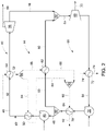
- FIG. 2 shows an example that may increase the efficiency of an ORC system using a low-temperature heat source stream by modifying the traditional ORC system 10.
- FIG. 2 shows a modified ORC system 40 that includes two pressure stages that utilize a single working fluid 42.
- the working fluid 42 may be a dry organic fluid.
- the working fluid 42 may be isobutane, butane, n-pentane, isopentane, isohexane, hexane, a siloxane, R245fa, any substance that exhibits a positive slope on the saturation line of a T-S diagram (i.e., is "dry"), or any combination thereof, among others.
- T-S temperatureentropy
- a dry organic fluid as the working fluid is particularly well-suited to generate power from a low-grade temperature heat source.
- non-dry organic fluids may be used as the working fluid, such as propane, R134a, or a combination thereof.
- FIG. 2 shows one example not covered by the invention of the modified ORC system 40 that includes a high pressure stage 44 with a high pressure pump 46 that is enabled to increase a pressure of a high pressure stream 48 of the working fluid 42.
- the high pressure stream 48 exits the high pressure pump 46 and enters a high pressure preheater 50 where energy is transferred to the high pressure stream 48 to increase the high pressure stream's 48 temperature.
- the high pressure preheater 50 may be a heat exchanger such as a shell and tube heat exchanger, a double pipe heat exchanger, a plate heat exchanger, a plate and shell heat exchanger, or any other device configured to transfer energy from one stream of fluid to another stream of fluid.
- the high pressure stream 48 may then enter a high pressure evaporator 54 where the high pressure stream 48 absorbs energy from a heat source stream 52. Upon absorbing energy from the heat source stream 52, the temperature of the high pressure stream 48 increases.
- the high pressure stream 48 is substantially all in a gaseous phase when exiting the high pressure evaporator 54.
- the high pressure stream 48 may exit the high pressure evaporator 54 as a superheated vapor and may contain between 0 Kelvin of superheat and 10 Kelvin of superheat; between 0 Kelvin of superheat and 15 Kelvin of superheat; between 0 Kelvin of superheat and 20 Kelvin of superheat; or anywhere therebetween upon exiting the high pressure evaporator 54.
- the high pressure evaporator 54 may be a heat exchanger such as a shell and tube heat exchanger, a double pipe heat exchanger, a plate heat exchanger, a plate and shell heat exchanger, or any other device configured to transfer energy from one stream of fluid to another stream of fluid.
- a heat exchanger such as a shell and tube heat exchanger, a double pipe heat exchanger, a plate heat exchanger, a plate and shell heat exchanger, or any other device configured to transfer energy from one stream of fluid to another stream of fluid.
- the high pressure stream 48 may enter a high pressure expander 56.
- the high pressure expander 56 is configured to rapidly expand the high pressure stream 48 and generate power 58 by converting a significant pressure drop of the high pressure stream 48 into work.
- the high pressure expander 56 may be a turbine or any other device configured to expand a working fluid and generate power.
- the high pressure stream 48 may remain a superheated vapor.
- the high pressure stream 48 may combine with a low pressure stream 60 of the working fluid 42 in a first mixer 62 to form a mixed enthalpy stream 64.
- the low pressure stream 60 is part of a low pressure stage 66 of the overall ORC 40.
- the low pressure stream 60 enters the first mixer 62 at a lower temperature than the high pressure stream 48. Therefore, in certain examples, the mixed enthalpy stream 64 exiting the first mixer 62 has a higher temperature than the low pressure stream 60, but a lower temperature than the high pressure stream 48.
- the mixed enthalpy stream 64 may be substantially all saturated gas with substantially no superheat and substantially no liquid.
- the modified ORC system may generate a 2 percent net power increase by placing the high pressure expander 56 in series with the low pressure expander 68 and reducing inlet superheat by increasing the low-pressure working fluid mass flow.
- the mixed enthalpy stream 64 may enter the low pressure expander 68, such that the low pressure expander 68 is in series with the high pressure expander 56.
- the low pressure expander 66 is configured to rapidly expand the mixed enthalpy stream 64 and generate power 70 by converting a significant pressure drop of the mixed enthalpy stream 64 into work.
- the high pressure expander 68 may be a turbine or any other device configured to expand a working fluid and generate power.
- the mixed enthalpy stream 64 may enter a condenser 72.
- the condenser 72 may be configured to cool the mixed enthalpy stream 64 such that substantially all of the working fluid 42 in the mixed enthalpy stream 64 exiting the condenser 72 is in a liquid phase.
- the condenser may include a heat sink stream 74.
- the heat sink stream may absorb heat from the mixed enthalpy stream 64 such that the mixed enthalpy stream's 64 temperature decreases in the condenser 72.
- the heat sink stream may comprise a fluid with a temperature substantially less than the temperature of the mixed enthalpy stream 64 entering the condenser 72.
- the heat sink stream may be water with a temperature between 5 °C and 25 °C or the ambient air temperature.
- the condenser 72 may be a heat exchanger such as a shell and tube heat exchanger, a plate heat exchanger, a fin-tube heat exchanger, or any other device configured to transfer energy from one stream of fluid to another stream of fluid.
- the mixed enthalpy stream 64 may exit the condenser 72 and enter a low pressure pump 76.
- the low pressure pump 76 is configured such that the mixed enthalpy stream 64 exiting the low pressure pump 76 has a higher pressure than the mixed enthalpy stream 64 entering the low pressure pump 76.
- the mixed enthalpy stream 64 may also enter a low pressure preheater 78 after exiting the low pressure pump 76.
- the low pressure preheater 78 transfers energy from a heat source stream 52 or another heat source stream to the mixed enthalpy stream 64.
- the low pressure preheater 78 may be a heat exchanger such as a shell and tube heat exchanger, a double pipe heat exchanger, a plate heat exchanger, a plate and shell heat exchanger, or any other device configured to transfer energy from one stream of fluid to another stream of fluid.
- a heat exchanger such as a shell and tube heat exchanger, a double pipe heat exchanger, a plate heat exchanger, a plate and shell heat exchanger, or any other device configured to transfer energy from one stream of fluid to another stream of fluid.
- the mixed enthalpy stream 64 exiting the low pressure preheater 78 may then be split into the high pressure stream 48 of the working fluid 42 and the low pressure stream 60 of the working fluid 42 in a first tee 80.
- the first tee 80 directs the high pressure stream 48 to the high pressure stage 44 and the low pressure stream 60 to the low pressure stage 66.
- the high pressure stream 48 may then enter the high pressure pump 46, and the cycle continues.
- the low pressure stream 60 may enter a low pressure evaporator 82.
- the low pressure evaporator 82 transfers energy from the heat source stream 52 or another heat source stream to the low pressure stream 60 such that the low pressure stream 60 exiting the low pressure evaporator 82 has a higher temperature than the low pressure stream 60 entering the low pressure evaporator 82.
- the low pressure stream 60 exiting the low pressure evaporator 82 may consist of the working fluid 42 primarily in a saturated liquid phase.
- the low pressure evaporator 82 may be a heat exchanger such as a shell and tube heat exchanger, a double pipe heat exchanger, a plate heat exchanger, a plate and shell heat exchanger, or any other device configured to transfer energy from one stream of fluid to another stream of fluid.
- the low pressure stream 60 may combine with the high pressure stream 48 in the first mixer 62 where the overall modified ORC system 40 continues to run.
- the heat source stream 52 of the modified ORC system 40 may be split into a high pressure preheating stream 84 and a low pressure evaporating stream 86 with a heat source tee 88.
- the high pressure preheating stream 84 may act as a heat source for the high pressure preheater 50 and the low pressure evaporating stream 86 may act as a heat source for the low pressure evaporator 82.
- the two streams 84, 86 may be mixed in a heat source mixer 90 to create a mixed heat source stream 92.
- the mixed heat source stream 92 may be used as a heat source for the low pressure preheater 78.
- Splitting the heat source stream 52 may enable the modified ORC system 40 to operate more efficiently than traditional ORCs.
- splitting the heat source stream 52 downstream from the high pressure evaporator 54 may increase the net power gain of the modified ORC system 40 by 3 percent. Therefore, when combined with the potential 2 percent net power gain caused by placing the high pressure expander 56 in series with the low pressure expander 68, the modified ORC system 40 may generate a net power gain of 5 percent or more, for example.
- the heat source stream 52 may not be split, but rather, may flow through the high pressure evaporator 54, the high pressure preheater 50, the low pressure evaporator 82, and the low pressure preheater 78 in any order.
- the high pressure evaporator 54, the high pressure preheater 50, the low pressure evaporator 82, and the low pressure preheater 78 may also have separate heat source streams. The separate heat source streams may or may not have different temperatures.
- the high pressure preheating stream 84 and the low pressure evaporating stream 86 may not combine in the heat source mixer 90 and either the high pressure preheating stream 84 or the low pressure evaporating stream 86, alone, may be the heat source of the low pressure preheater 78.
- the low pressure preheater 78 may have a separate heat source stream.
- modified ORC system 40 may include more than one preheater upstream from an evaporator. Adding additional preheaters can decrease the energy input required to run the modified ORC system 40.
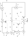
- FIG. 3 shows another example.
- the first tee 80 is positioned upstream of the low pressure pump 76.
- FIG. 3 shows the first tee 80 splitting the mixed enthalpy stream 64 into the high pressure stream 48 and the low pressure stream 60 prior to the mixed enthalpy stream 64 entering the low pressure pump 76. Therefore, the high pressure stream 48 enters the high pressure pump 46 and the low pressure stream 60 enters the low pressure pump 76 after exiting the first tee 80.
- the high pressure pump 46 has a power input 100 greater than a power input 101 to the low pressure pump 76 so that the high pressure stream 48 may reach a higher pressure upon exiting the high pressure pump 46 than the low pressure stream 60 exiting the low pressure pump 76.
- the mixed enthalpy stream 64 does not pass through the low pressure preheater 78. Rather, the mixed enthalpy stream 64 splits into the high pressure stream 48 and the low pressure stream 60 upstream from the low pressure preheater 78 such that only the low pressure stream 60 flows through the low pressure preheater 78.
- FIG. 3 also illustrates the heat source stream 52 being split in the heat source tee 88 and then distributing the high pressure preheating stream 84 to the high pressure preheater 50 and the low pressure evaporating stream 86 to the low pressure evaporator 82.
- the high pressure evaporator 54, the high pressure preheater 50, and the low pressure evaporator 82 may use alternative heat source configurations as mentioned with respect to the examples discussed above.
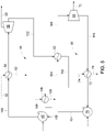
- FIG. 4 shows another example.
- the high pressure expander 56 and the low pressure expander 68 are in a parallel configuration as opposed to the series configuration portrayed in FIGS. 2 and 3 . Therefore, the low pressure stream 60 enters the low pressure expander 68 prior to the first mixer 62.
- the high pressure stream 48 combines with the low pressure stream 60 downstream from the low pressure expander 68 such that the high pressure stream 48 never enters the low pressure expander 68 in the form of the mixed enthalpy stream 64.
- FIG. 4 also illustrates the heat source stream 52 being split in the heat source tee 88 and then distributing the high pressure preheating stream 84 to the high pressure preheater 50 and the low pressure evaporating stream 86 to the low pressure evaporator 82.
- the high pressure evaporator 54, the high pressure preheater 50, the low pressure evaporator 82, and the low pressure preheater 78 may use alternative heat source configurations as mentioned with respect to the examples discussed above.
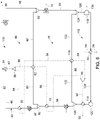
- FIG. 5 shows another example.
- the high pressure stage 44 and the low pressure stage 66 are separate cycles that each have a separate working fluid 102, 104.
- the high pressure stage 44 has a high pressure working fluid 102 and the low pressure stage has a low pressure working fluid 104.
- the high pressure working fluid 102 and the low pressure working fluid 104 may have the same composition.
- the high pressure working fluid 102 and the low pressure working fluid 104 may have different compositions.
- FIG. 5 shows an example where the high pressure working fluid 102 is used as a heat source for the low pressure evaporator 82.
- the heat source for the low pressure evaporator 82 may be the heat source stream 52 used with the high pressure evaporator 54.
- the high pressure working fluid 102 may not be used as a heat source, and the low pressure evaporator 82 may use a separate heat source.
- FIG. 5 also includes a second condenser 106.
- the second condenser 106 shown in FIG. 5 may be configured to cool the high pressure working fluid 102 exiting the low pressure evaporator 82 such that the high pressure working fluid 102 exiting the second condenser 106 is substantially all liquid.
- the second condenser may utilize a second heat sink stream 108.
- the second condenser may utilize the heat sink stream 74 of the first condenser 72.
- FIG. 6 illustrates the embodiment of the present invention, and shows a modified ORC system 110 that includes three pressure stages.
- the modified ORC system 110 of FIG. 6 includes a third pressure stage 112 in addition to the high pressure stage 44 and the low pressure stage 66 of the modified ORC system 40.
- the third pressure stage 112 includes a third pressure preheater 114, a third pressure evaporator 116, a third pressure expander 118, a third pressure pump 120, and a third stream 122 of the working fluid 42. Additionally, a second mixer 124 and a second tee 126 are included.
- the modified ORC system 110 of FIG. 6 operates in a similar manner to the modified ORC system 40 of FIG. 2 , but includes an additional pressure stage.
- FIG 6 shows an embodiment where instead of entering the condenser 72, the mixed enthalpy stream 64 enters the second mixer 124 where it combines with the third stream 122 forming a second mixed enthalpy stream 128.
- the second mixed enthalpy stream 128 enters the third pressure expander 118 where a pressure drop is created between the second mixed enthalpy stream 128 entering the expander 118 and the second mixed enthalpy stream 128 exiting the expander 128.
- the pressure drop is used to generate power 130.
- the third pressure expander 118 may be configured to rapidly expand the second mixed enthalpy stream 128 and to generate power 130 by converting a significant pressure drop of the second mixed enthalpy stream 128 into work.
- the third pressure expander 118 may be a turbine or any other device configured to expand a working fluid and generate power.
- the second mixed enthalpy stream 128 enters the condenser 72 where the second mixed enthalpy stream 128 is cooled so that substantially all of the second mixed enthalpy stream 128 is in a liquid phase.
- the second mixed enthalpy stream 128 enters the third pressure pump 120 and the third pressure preheater 114.
- the third pressure preheater 114 utilizes the same heat source stream 52 as the high pressure evaporator 54, the high pressure preheater 50, the low pressure evaporator 82, and/or the low pressure preheater 78.
- the third pressure preheater 114 may include a separate heat source stream.
- the third pressure preheater 114 may be a heat exchanger such as a shell and tube heat exchanger, a double pipe heat exchanger, a plate heat exchanger, a plate and shell heat exchanger, or any other device configured to transfer energy from one stream of fluid to another stream of fluid.
- a heat exchanger such as a shell and tube heat exchanger, a double pipe heat exchanger, a plate heat exchanger, a plate and shell heat exchanger, or any other device configured to transfer energy from one stream of fluid to another stream of fluid.
- the second mixed enthalpy stream 128 is split into the mixed enthalpy stream 64 and the third stream 122 in the second tee 126.
- the third stream 122 enters the third pressure evaporator 116.
- the third pressure evaporator 116 utilizes the same heat source stream 52 as the high pressure evaporator 54, the high pressure preheater 50, the low pressure evaporator 82, and/or the low pressure preheater 78.
- the third pressure evaporator 116 may include a separate heat source stream or share the same heat source as the third pressure preheater 114.
- the third pressure evaporator 116 may be a heat exchanger such as a shell and tube heat exchanger, a double pipe heat exchanger, a plate heat exchanger, a plate and shell heat exchanger, or any other device configured to transfer energy from one stream of fluid to another stream of fluid.
- a heat exchanger such as a shell and tube heat exchanger, a double pipe heat exchanger, a plate heat exchanger, a plate and shell heat exchanger, or any other device configured to transfer energy from one stream of fluid to another stream of fluid.
- examples not covered by the invention may include more than three pressure stages.
- a stream of working fluid exiting a given expander combines with the next lowest pressure stage's working fluid prior to entering that next lower pressure stage's expander. This process continues until no more pressure stages exist. Once no more pressure stages exist, the stream exiting the final pressure stage's expander enters into a condenser before the stream is cycled back into the system.
Landscapes
- Engineering & Computer Science (AREA)
- Chemical & Material Sciences (AREA)
- Combustion & Propulsion (AREA)
- Mechanical Engineering (AREA)
- General Engineering & Computer Science (AREA)
- Engine Equipment That Uses Special Cycles (AREA)
Description
- The subject matter disclosed herein relates to a multi-pressure organic Rankine cycle using a dry organic working fluid.
-
WO 2008/125827 A2 discloses an organic Rankine cycle apparatus for generating power from two different sources of heat at different temperatures comprising a lower pressure organic working fluid circuit and a higher pressure organic working fluid circuit in fluid communication with each other.US 2013/341929 A1 discloses an organic flash cycle. - Waste heat recovery systems may be employed to recover low-grade heat from industrial and commercial processes and operations. For example, waste heat recovery systems may be used to recover low-grade heat from hot exhaust gases produced by gas turbines. Waste heat recovery systems that implement an organic Rankine cycle (ORC) with an organic working fluid may be particularly efficient at recovering low-grade heat due to the relatively low phase change enthalpies of organic fluids.
- Additionally, ORC systems can be utilized in geothermal power plants. Geothermal power plants seek to utilize natural reservoirs of steam and hot water (e.g., brine) to generate electricity. The steam and hot water from geothermal reservoirs is generally obtained at low-grade temperatures, and thus, an ORC system may be an efficient method for generating electricity using a geothermal reservoir heat source.
- Traditional ORCs tend to be less efficient when the temperature of the heat source decreases. Therefore, a modified ORC system that can generate electricity using low-grade heat sources more efficiently is desired.
- The present invention is defined in the accompanying claims.
- In one example not covered by the invention, an organic Rankine cycle includes a dry organic working fluid, a high pressure stage, and a low pressure stage. The high pressure stage includes a high pressure pump, a high pressure evaporator, and a high pressure expander. Similarly, the low pressure stage includes a low pressure pump, a low pressure evaporator, and a low pressure expander. The organic Rankine cycle also includes a mixer configured to combine a high pressure stream of the dry organic working fluid exiting the high pressure expander and a low pressure stream of the dry organic working fluid exiting the low pressure evaporator, wherein a mixed enthalpy stream exits the mixer and enters the low pressure expander. Also, the organic Rankine cycle has a condenser configured to condense the mixed enthalpy stream exiting the low pressure expander and a tee configured to split the mixed enthalpy stream exiting the condenser into the high pressure stream and the low pressure stream, wherein the high pressure stream enters the high pressure pump and the low pressure stream enters the low pressure evaporator.
- These and other features, aspects, and advantages of the present invention will become better understood when the following detailed description is read with reference to the accompanying drawings in which like characters represent like parts throughout the drawings, wherein:
-
FIG. 1 shows an example of a traditional organic Rankine cycle. -
FIG. 2 illustrates a modified organic Rankine cycle system that includes two pressure stages with two expanders arranged in series. -
FIG. 3 illustrates a modified organic Rankine cycle system that includes two pressure stages with two expanders arranged in series. -
FIG. 4 illustrates a modified organic Rankine cycle system that includes two pressure stages with two expanders arranged in parallel. -
FIG. 5 illustrates a modified organic Rankine cycle system that includes two pressure stages arranged in a cascade configuration. -
FIG. 6 shows an embodiment of the present invention that illustrates a modified organic Rankine cycle system that includes three pressure stages with three expanders arranged in series. - One or more specific embodiments will be described below. In an effort to provide a concise description of these embodiments, all features of an actual implementation may not be described in the specification. It should be appreciated that in the development of any such actual implementation, as in any engineering or design project, numerous implementation-specific decisions must be made to achieve the developers' specific goals, such as compliance with system-related and businessrelated constraints, which may vary from one implementation to another. Moreover, it should be appreciated that such a development effort might be complex and time consuming, but would nevertheless be a routine undertaking of design, fabrication, and manufacture for those of ordinary skill having the benefit of this disclosure.
- When introducing elements of various embodiments of the present invention, the articles "a," "an," "the," and "said" are intended to mean that there are one or more of the elements. The terms "comprising," "including," and "having" are intended to be inclusive and mean that there may be additional elements other than the listed elements. Furthermore, any numerical examples in the following discussion are intended to be non-limiting, and thus additional numerical values, ranges, and percentages are within the scope of the disclosed embodiments.
- In general, traditional ORC systems may circulate an organic working fluid in a closed loop through a cycle of expansion and pressurization to convert heat into work. For example, the working fluid may be directed through a heat exchanger where the working fluid may absorb heat from a heat source, such as geothermal water or steam (e.g., brine), to vaporize the working fluid. The organic working fluid possesses a boiling point that is less than the boiling point of water, which allows the ORC to effectively generate power from low-temperature heat sources. The vaporized working fluid may then be expanded across a turbine to drive a load, such as a generator, that produces electricity. The expanded working fluid may then be directed to another heat exchanger to condense the working fluid into a liquid. The liquid working fluid may then be pressurized in a pump and returned to the first heat exchanger where the cycle repeats. Typical ORC systems may employ a refrigerant, such as R134a or R245fa, as the organic working fluid and may operate at temperatures of approximately 80°C to 200°C. However, it may be desirable to utilize other working fluids and operating temperatures when utilizing a multi-pressure system and a low-grade temperature heat source.
- As discussed herein, multi-level ORC systems can be used to improve the efficiency of a traditional ORC system. A multi-level ORC can include stages that operate at different temperatures or at different pressures. ORC systems that utilize multiple cycles operating at different temperatures are generally configured in a cascade arrangement. A cascade arrangement includes two or more individual ORCs that each comprises a closed loop Rankine cycle. Cascade arrangements can thus take advantage of multiple working fluids that possess different thermodynamic properties to maximize efficiency. However, multi-level ORC systems operating at different temperatures require a higher temperature heat source in order to fully maximize the power output.
- In certain examples discussed herein, multi-pressure ORC systems utilize at least two stages operating at different pressures. A multi-pressure ORC can also be arranged in a cascade formation. Alternatively, the multi-pressure ORC may be arranged such that two turbines or expanders are positioned in series, thereby combining the working fluid from a high pressure ORC and the working fluid from a lower pressure ORC. Such a configuration may be desirable because the high pressure working fluid exits a high pressure expander as a superheated vapor, and increases the temperature of the low pressure working fluid thereby requiring less overall energy input to the system. This feature of the ORC configuration enhances the efficiency of the overall system in comparison to traditional ORCs.
- The present disclosure is directed to techniques for enhancing the efficiency of systems generating electricity from low-grade temperature heat sources, such as water or steam (e.g., brine) from a geothermal reservoir. Such an electricity generation system may include a modified organic Rankine cycle (ORC) that utilizes one, dry organic solvent as the working fluid, but contains at least two stages that operate at different pressures. The two stages may be desirable to reduce a temperature difference between the boiling working fluid and the heat source. The heat source may be used to boil the working fluid at a high pressure and temperature first, and then boil the working fluid at a lower pressure and temperature. Thus, two stages minimize the temperature differences during boiling and exploit as much of the available energy in the heat source as possible. To create the two stages, at least two expanders or turbines may be placed in series. The output from a high pressure expander may be mixed with a low pressure stream of the working fluid prior to entering a low pressure expander. This configuration may enhance efficiency because the output from the high pressure expander further heats the working fluid entering the low pressure expander without requiring additional energy input to the overall system. Therefore, less energy input is required than in traditional ORCs. Upon exiting the low pressure expander, the combined working fluid is condensed in a condenser and then is repressurized in one or more pumps.
- An example not covered by the invention may be utilized to generate electricity as part of a binary fluid geothermal power plant. Generally, geothermal power plants utilize geothermal reservoirs of steam and hot water (e.g., brine) as energy sources for the creation of electricity. Single fluid geothermal power plants send brine directly through at least one turbine or expander to generate electricity. Conversely, a binary fluid geothermal power plant incorporates heat exchangers such that the brine (i.e., the first fluid) transfers energy to a working fluid (i.e., the second fluid) in an ORC. In a binary fluid geothermal power plant, the working fluid in the ORC passes through the turbine or heat exchanger to generate electricity. The working fluid in an ORC generally has an evaporation temperature less than water thus requiring less energy to convert into a gaseous state.
- A binary fluid geothermal power plant may provide for enhanced electricity generation. However, traditional binary fluid geothermal power plants tend to operate at low efficiencies when the geothermal source is available at only relatively low temperatures. As used herein, relatively low temperatures for a heat source may be between 100 °C and 200 °C, between 120 °C and 160 °C, between 130 °C and 150 °C, or anywhere therebetween.
- Turning to the figures,
FIG. 1 shows an example not covered by the invention of a traditional, singlestage ORC system 10 for reference. A workingfluid 12 flows through the various components of theORC 10 to generatepower 14. The working fluid is sent through apump 16 to pressurize the working fluid to a desired level. The working fluid then flows into anevaporator 18, where it is heated to a desired temperature. In certain examples, theevaporator 18 may be a heat exchanger such as a shell and tube heat exchanger, a plate heat exchanger, a plate and shell heat exchanger, or any other device configured to transfer energy from one stream of fluid to another stream of fluid. Theevaporator 18 includes aheat source stream 20, which transfers energy from theheat source stream 20 to the workingfluid 12. The heated workingfluid 12 then flows into an expander 22 where the pressure of the workingfluid 12 drops significantly. The pressure drop across the expander 22 can be used to generate power orelectricity 14. The expander 22 may be a turbine or any other device capable of generating power through the expansion of a working fluid. After expansion, the workingfluid 12 enters acondenser 24 to cool the workingfluid 12 so that substantially all of the workingfluid 12 is in liquid form before entering thepump 16. Thecondenser 24 may be a heat exchanger such as a shell and tube heat exchanger, a plate heat exchanger, a plate and shell heat exchanger, or any other device configured to transfer energy from one stream of fluid to another stream of fluid. Thecondenser 24 also includes aheat sink stream 26 that absorbs energy from the workingfluid 12 enabling the workingfluid 12 to change from a gaseous state to a liquid state. - The
traditional ORC system 10 generates power at a relatively low efficiency when theheat source stream 20 includes a low-temperature fluid. Therefore, it is desirable to modify thetraditional ORC system 10 so that power generation may be more efficient when only a low-temperature heat source stream is available. -
FIG. 2 shows an example that may increase the efficiency of an ORC system using a low-temperature heat source stream by modifying thetraditional ORC system 10.FIG. 2 shows a modifiedORC system 40 that includes two pressure stages that utilize a single workingfluid 42. - In certain embodiments, the working
fluid 42 may be a dry organic fluid. For example, the workingfluid 42 may be isobutane, butane, n-pentane, isopentane, isohexane, hexane, a siloxane, R245fa, any substance that exhibits a positive slope on the saturation line of a T-S diagram (i.e., is "dry"), or any combination thereof, among others. By having a positive slope along the saturation line of the temperatureentropy (T-S) diagram, the working fluid is likely to superheat rather than condense upon expansion. Additionally, the overall power input required for the system may decrease substantially when utilizing a dry organic fluid as the working fluid because of the low boiling points of such fluids. The use of a dry organic fluid as the working fluid is particularly well-suited to generate power from a low-grade temperature heat source. In other examples not covered by the invention, non-dry organic fluids may be used as the working fluid, such as propane, R134a, or a combination thereof. -
FIG. 2 shows one example not covered by the invention of the modifiedORC system 40 that includes ahigh pressure stage 44 with ahigh pressure pump 46 that is enabled to increase a pressure of ahigh pressure stream 48 of the workingfluid 42. In certain examples, thehigh pressure stream 48 exits thehigh pressure pump 46 and enters ahigh pressure preheater 50 where energy is transferred to thehigh pressure stream 48 to increase the high pressure stream's 48 temperature. Thehigh pressure preheater 50 may be a heat exchanger such as a shell and tube heat exchanger, a double pipe heat exchanger, a plate heat exchanger, a plate and shell heat exchanger, or any other device configured to transfer energy from one stream of fluid to another stream of fluid. Thehigh pressure stream 48 may then enter ahigh pressure evaporator 54 where thehigh pressure stream 48 absorbs energy from aheat source stream 52. Upon absorbing energy from theheat source stream 52, the temperature of thehigh pressure stream 48 increases. In certain examples, thehigh pressure stream 48 is substantially all in a gaseous phase when exiting thehigh pressure evaporator 54. For example, thehigh pressure stream 48 may exit thehigh pressure evaporator 54 as a superheated vapor and may contain between 0 Kelvin of superheat and 10 Kelvin of superheat; between 0 Kelvin of superheat and 15 Kelvin of superheat; between 0 Kelvin of superheat and 20 Kelvin of superheat; or anywhere therebetween upon exiting thehigh pressure evaporator 54. Additionally, thehigh pressure evaporator 54 may be a heat exchanger such as a shell and tube heat exchanger, a double pipe heat exchanger, a plate heat exchanger, a plate and shell heat exchanger, or any other device configured to transfer energy from one stream of fluid to another stream of fluid. - After exiting the
high pressure evaporator 54, thehigh pressure stream 48 may enter ahigh pressure expander 56. In certain examples, thehigh pressure expander 56 is configured to rapidly expand thehigh pressure stream 48 and generatepower 58 by converting a significant pressure drop of thehigh pressure stream 48 into work. Thehigh pressure expander 56 may be a turbine or any other device configured to expand a working fluid and generate power. After exiting thehigh pressure expander 56, thehigh pressure stream 48 may remain a superheated vapor. - After exiting the
high pressure expander 56, thehigh pressure stream 48 may combine with alow pressure stream 60 of the workingfluid 42 in afirst mixer 62 to form amixed enthalpy stream 64. Thelow pressure stream 60 is part of alow pressure stage 66 of theoverall ORC 40. In certain examples, thelow pressure stream 60 enters thefirst mixer 62 at a lower temperature than thehigh pressure stream 48. Therefore, in certain examples, themixed enthalpy stream 64 exiting thefirst mixer 62 has a higher temperature than thelow pressure stream 60, but a lower temperature than thehigh pressure stream 48. Also, in certain examples, themixed enthalpy stream 64 may be substantially all saturated gas with substantially no superheat and substantially no liquid. By combining thehigh pressure stream 48 and thelow pressure stream 60 in thefirst mixer 62, the amount of heat input required for the stream entering alow pressure expander 68 substantially decreases because of the heat being transferred from thehigh pressure stream 48 consisting of superheated vapor to thelow pressure stream 60 consisting of nearly saturated fluid. As a non-limiting example, the modified ORC system may generate a 2 percent net power increase by placing thehigh pressure expander 56 in series with thelow pressure expander 68 and reducing inlet superheat by increasing the low-pressure working fluid mass flow. - The
mixed enthalpy stream 64 may enter thelow pressure expander 68, such that thelow pressure expander 68 is in series with thehigh pressure expander 56. Thelow pressure expander 66 is configured to rapidly expand themixed enthalpy stream 64 and generatepower 70 by converting a significant pressure drop of themixed enthalpy stream 64 into work. Thehigh pressure expander 68 may be a turbine or any other device configured to expand a working fluid and generate power. - Upon exiting the
low pressure expander 68, themixed enthalpy stream 64 may enter acondenser 72. In certain embodiments, thecondenser 72 may be configured to cool themixed enthalpy stream 64 such that substantially all of the workingfluid 42 in themixed enthalpy stream 64 exiting thecondenser 72 is in a liquid phase. The condenser may include aheat sink stream 74. The heat sink stream may absorb heat from themixed enthalpy stream 64 such that the mixed enthalpy stream's 64 temperature decreases in thecondenser 72. The heat sink stream may comprise a fluid with a temperature substantially less than the temperature of themixed enthalpy stream 64 entering thecondenser 72. As a non-limiting example, the heat sink stream may be water with a temperature between 5 °C and 25 °C or the ambient air temperature. In certain configurations, thecondenser 72 may be a heat exchanger such as a shell and tube heat exchanger, a plate heat exchanger, a fin-tube heat exchanger, or any other device configured to transfer energy from one stream of fluid to another stream of fluid. - The
mixed enthalpy stream 64 may exit thecondenser 72 and enter alow pressure pump 76. Thelow pressure pump 76 is configured such that themixed enthalpy stream 64 exiting thelow pressure pump 76 has a higher pressure than themixed enthalpy stream 64 entering thelow pressure pump 76. In certain examples, themixed enthalpy stream 64 may also enter alow pressure preheater 78 after exiting thelow pressure pump 76. Thelow pressure preheater 78 transfers energy from aheat source stream 52 or another heat source stream to themixed enthalpy stream 64. Thelow pressure preheater 78 may be a heat exchanger such as a shell and tube heat exchanger, a double pipe heat exchanger, a plate heat exchanger, a plate and shell heat exchanger, or any other device configured to transfer energy from one stream of fluid to another stream of fluid. - In certain examples, the
mixed enthalpy stream 64 exiting thelow pressure preheater 78 may then be split into thehigh pressure stream 48 of the workingfluid 42 and thelow pressure stream 60 of the workingfluid 42 in afirst tee 80. Thefirst tee 80 directs thehigh pressure stream 48 to thehigh pressure stage 44 and thelow pressure stream 60 to thelow pressure stage 66. Thehigh pressure stream 48 may then enter thehigh pressure pump 46, and the cycle continues. Thelow pressure stream 60 may enter alow pressure evaporator 82. Thelow pressure evaporator 82 transfers energy from theheat source stream 52 or another heat source stream to thelow pressure stream 60 such that thelow pressure stream 60 exiting thelow pressure evaporator 82 has a higher temperature than thelow pressure stream 60 entering thelow pressure evaporator 82. As discussed above, thelow pressure stream 60 exiting thelow pressure evaporator 82 may consist of the workingfluid 42 primarily in a saturated liquid phase. Thelow pressure evaporator 82 may be a heat exchanger such as a shell and tube heat exchanger, a double pipe heat exchanger, a plate heat exchanger, a plate and shell heat exchanger, or any other device configured to transfer energy from one stream of fluid to another stream of fluid. After exiting thelow pressure evaporator 82, thelow pressure stream 60 may combine with thehigh pressure stream 48 in thefirst mixer 62 where the overall modifiedORC system 40 continues to run. - In one example, the
heat source stream 52 of the modifiedORC system 40 may be split into a highpressure preheating stream 84 and a lowpressure evaporating stream 86 with aheat source tee 88. The highpressure preheating stream 84 may act as a heat source for thehigh pressure preheater 50 and the lowpressure evaporating stream 86 may act as a heat source for thelow pressure evaporator 82. After the highpressure preheating stream 84 exits thehigh pressure preheater 50 and the lowpressure evaporating stream 86 exits thelow pressure evaporator 82, the twostreams heat source stream 92. In certain examples, the mixedheat source stream 92 may be used as a heat source for thelow pressure preheater 78. Splitting theheat source stream 52 may enable the modifiedORC system 40 to operate more efficiently than traditional ORCs. As a non-limiting example, splitting theheat source stream 52 downstream from thehigh pressure evaporator 54 may increase the net power gain of the modifiedORC system 40 by 3 percent. Therefore, when combined with the potential 2 percent net power gain caused by placing thehigh pressure expander 56 in series with thelow pressure expander 68, the modifiedORC system 40 may generate a net power gain of 5 percent or more, for example. - In another example, the
heat source stream 52 may not be split, but rather, may flow through thehigh pressure evaporator 54, thehigh pressure preheater 50, thelow pressure evaporator 82, and thelow pressure preheater 78 in any order. In another example, thehigh pressure evaporator 54, thehigh pressure preheater 50, thelow pressure evaporator 82, and thelow pressure preheater 78 may also have separate heat source streams. The separate heat source streams may or may not have different temperatures. Finally, in one example, the highpressure preheating stream 84 and the lowpressure evaporating stream 86 may not combine in the heat source mixer 90 and either the highpressure preheating stream 84 or the lowpressure evaporating stream 86, alone, may be the heat source of thelow pressure preheater 78. Alternatively, thelow pressure preheater 78 may have a separate heat source stream. - It should be appreciated by those with skill in the art that additional pumps, preheaters, evaporators, expanders, and condensers may be utilized in the modified
ORC system 40 in addition to those specifically mentioned above. For example, the modifiedORC system 40 may include more than one preheater upstream from an evaporator. Adding additional preheaters can decrease the energy input required to run the modifiedORC system 40. -
FIG. 3 shows another example. InFIG. 3 , thefirst tee 80 is positioned upstream of thelow pressure pump 76.FIG. 3 shows thefirst tee 80 splitting themixed enthalpy stream 64 into thehigh pressure stream 48 and thelow pressure stream 60 prior to themixed enthalpy stream 64 entering thelow pressure pump 76. Therefore, thehigh pressure stream 48 enters thehigh pressure pump 46 and thelow pressure stream 60 enters thelow pressure pump 76 after exiting thefirst tee 80. In certain embodiments, thehigh pressure pump 46 has apower input 100 greater than apower input 101 to thelow pressure pump 76 so that thehigh pressure stream 48 may reach a higher pressure upon exiting thehigh pressure pump 46 than thelow pressure stream 60 exiting thelow pressure pump 76. Additionally, in the example shown inFIG. 3 themixed enthalpy stream 64 does not pass through thelow pressure preheater 78. Rather, themixed enthalpy stream 64 splits into thehigh pressure stream 48 and thelow pressure stream 60 upstream from thelow pressure preheater 78 such that only thelow pressure stream 60 flows through thelow pressure preheater 78. -
FIG. 3 also illustrates theheat source stream 52 being split in theheat source tee 88 and then distributing the highpressure preheating stream 84 to thehigh pressure preheater 50 and the lowpressure evaporating stream 86 to thelow pressure evaporator 82. However, it should be appreciated by those skilled in the art that thehigh pressure evaporator 54, thehigh pressure preheater 50, and thelow pressure evaporator 82, may use alternative heat source configurations as mentioned with respect to the examples discussed above. -
FIG. 4 shows another example. InFIG. 4 thehigh pressure expander 56 and thelow pressure expander 68 are in a parallel configuration as opposed to the series configuration portrayed inFIGS. 2 and3 . Therefore, thelow pressure stream 60 enters thelow pressure expander 68 prior to thefirst mixer 62. Similarly, thehigh pressure stream 48 combines with thelow pressure stream 60 downstream from thelow pressure expander 68 such that thehigh pressure stream 48 never enters thelow pressure expander 68 in the form of themixed enthalpy stream 64. - Again,
FIG. 4 also illustrates theheat source stream 52 being split in theheat source tee 88 and then distributing the highpressure preheating stream 84 to thehigh pressure preheater 50 and the lowpressure evaporating stream 86 to thelow pressure evaporator 82. However, it should be appreciated by those skilled in the art that thehigh pressure evaporator 54, thehigh pressure preheater 50, thelow pressure evaporator 82, and thelow pressure preheater 78 may use alternative heat source configurations as mentioned with respect to the examples discussed above. -
FIG. 5 shows another example. InFIG. 5 thehigh pressure stage 44 and thelow pressure stage 66 are separate cycles that each have a separate workingfluid high pressure stage 44 has a highpressure working fluid 102 and the low pressure stage has a lowpressure working fluid 104. In certain examples, the highpressure working fluid 102 and the lowpressure working fluid 104 may have the same composition. In alternate examples, the highpressure working fluid 102 and the lowpressure working fluid 104 may have different compositions.FIG. 5 shows an example where the highpressure working fluid 102 is used as a heat source for thelow pressure evaporator 82. In alternative examples, the heat source for thelow pressure evaporator 82 may be theheat source stream 52 used with thehigh pressure evaporator 54. In other examples, the highpressure working fluid 102 may not be used as a heat source, and thelow pressure evaporator 82 may use a separate heat source. -
FIG. 5 also includes asecond condenser 106. Thesecond condenser 106 shown inFIG. 5 may be configured to cool the highpressure working fluid 102 exiting thelow pressure evaporator 82 such that the highpressure working fluid 102 exiting thesecond condenser 106 is substantially all liquid. In certain configurations, the second condenser may utilize a secondheat sink stream 108. In other examples, the second condenser may utilize theheat sink stream 74 of thefirst condenser 72. - The embodiment according to the invention includes more than two pressure stages as illustrated in
FIG. 6. FIG. 6 illustrates the embodiment of the present invention, and shows a modifiedORC system 110 that includes three pressure stages. The modifiedORC system 110 ofFIG. 6 includes athird pressure stage 112 in addition to thehigh pressure stage 44 and thelow pressure stage 66 of the modifiedORC system 40. Thethird pressure stage 112 includes athird pressure preheater 114, athird pressure evaporator 116, athird pressure expander 118, athird pressure pump 120, and athird stream 122 of the workingfluid 42. Additionally, asecond mixer 124 and asecond tee 126 are included. The modifiedORC system 110 ofFIG. 6 operates in a similar manner to the modifiedORC system 40 ofFIG. 2 , but includes an additional pressure stage. -
FIG 6 . shows an embodiment where instead of entering thecondenser 72, themixed enthalpy stream 64 enters thesecond mixer 124 where it combines with thethird stream 122 forming a secondmixed enthalpy stream 128. The secondmixed enthalpy stream 128 enters thethird pressure expander 118 where a pressure drop is created between the secondmixed enthalpy stream 128 entering theexpander 118 and the secondmixed enthalpy stream 128 exiting theexpander 128. The pressure drop is used to generatepower 130. Thethird pressure expander 118 may be configured to rapidly expand the secondmixed enthalpy stream 128 and to generatepower 130 by converting a significant pressure drop of the secondmixed enthalpy stream 128 into work. Thethird pressure expander 118 may be a turbine or any other device configured to expand a working fluid and generate power. - The second
mixed enthalpy stream 128 enters thecondenser 72 where the secondmixed enthalpy stream 128 is cooled so that substantially all of the secondmixed enthalpy stream 128 is in a liquid phase. Next, the secondmixed enthalpy stream 128 enters thethird pressure pump 120 and thethird pressure preheater 114. According to the invention, thethird pressure preheater 114 utilizes the sameheat source stream 52 as thehigh pressure evaporator 54, thehigh pressure preheater 50, thelow pressure evaporator 82, and/or thelow pressure preheater 78. In alternate examples not covered by the invention, thethird pressure preheater 114 may include a separate heat source stream. In certain examples not covered by the invention, thethird pressure preheater 114 may be a heat exchanger such as a shell and tube heat exchanger, a double pipe heat exchanger, a plate heat exchanger, a plate and shell heat exchanger, or any other device configured to transfer energy from one stream of fluid to another stream of fluid. - Finally, the second
mixed enthalpy stream 128 is split into themixed enthalpy stream 64 and thethird stream 122 in thesecond tee 126. Thethird stream 122 enters thethird pressure evaporator 116. According to the invention, thethird pressure evaporator 116 utilizes the sameheat source stream 52 as thehigh pressure evaporator 54, thehigh pressure preheater 50, thelow pressure evaporator 82, and/or thelow pressure preheater 78. In alternate examples not covered by the invention, thethird pressure evaporator 116 may include a separate heat source stream or share the same heat source as thethird pressure preheater 114. In certain examples not covered by the invention, thethird pressure evaporator 116 may be a heat exchanger such as a shell and tube heat exchanger, a double pipe heat exchanger, a plate heat exchanger, a plate and shell heat exchanger, or any other device configured to transfer energy from one stream of fluid to another stream of fluid. - It should be understood by those skilled in the art that examples not covered by the invention may include more than three pressure stages. In the case of more than three pressure stages, a stream of working fluid exiting a given expander combines with the next lowest pressure stage's working fluid prior to entering that next lower pressure stage's expander. This process continues until no more pressure stages exist. Once no more pressure stages exist, the stream exiting the final pressure stage's expander enters into a condenser before the stream is cycled back into the system.
Claims (8)
- An organic Rankine cycle comprising:a dry organic working fluid flowing in a high pressure stream (48), a low pressure stream (60) and a third stream (122);a high pressure stage (44) through which the high pressure stream (48) flows, wherein the high pressure stage comprises a high pressure pump (46), a high pressure preheater (50), a high pressure evaporator (54) and a high pressure expander (56);a low pressure stage (66) fluidly coupled to the high pressure stage (44), wherein the low pressure stream (60) flows through the low pressure stage (66), wherein the low pressure stage comprises a low pressure pump (76), a low pressure preheater (78), a low pressure evaporator (82) and a low pressure expander (68);a third pressure stage (112) through which the third stream (122) flows, wherein the third pressure stage comprises a third pressure pump (120), a third pressure preheater (114), a third pressure evaporator (116) and a third pressure expander (118), wherein the third pressure stage is fluidly coupled to the low pressure stage;a first mixer (62) configured to combine the high pressure stream (48) and the low pressure stream (60), wherein a first mixed enthalpy stream (64) exits the first mixer (62), wherein the first mixer (62) is configured to combine the high pressure stream (48) exiting the high pressure expander (56) and the low pressure stream (60) exiting the low pressure evaporator (82) such that the high pressure expander (56) and the low pressure expander (68) are arranged in series;a second mixer (124) configured to combine the first mixed enthalpy stream (64) and the third stream (122), wherein a second mixed enthalpy stream (128) exits the second mixer (124);a condenser (72) configured to condense the second mixed enthalpy stream (128);a first tee (80) configured to split the first mixed enthalpy stream (64) into the high pressure stream (48) and the low pressure stream (60); anda second tee (126) configured to split the second mixed enthalpy stream (128) exiting the condenser (72) into the first mixed enthalpy stream (64) and the third stream (122);wherein a heat source stream (52) configured to supply thermal energy to the high pressure evaporator, after exiting the high pressure evaporator (54) is split in a heat source stream tee (88) such that a high pressure preheating stream (84) enters the high pressure preheater (50) and a low pressure evaporating stream (86) enters the low pressure evaporator (82), and wherein the high pressure preheating stream (84) and the low pressure evaporating stream (86) combine in a heat source mixer (90) before entering the third pressure preheater (114).
- The organic Rankine cycle of claim 1, wherein a first pressure of the high pressure stream (48) is larger than a second pressure of the low pressure stream (60).
- The organic Rankine cycle of claim 1 or claim 2, wherein the high pressure evaporator (54) and the low pressure evaporator (82) are arranged in series, wherein a single heat source stream (52) supplies energy to the high pressure evaporator (54) and the low pressure evaporator (82), and wherein the low pressure evaporator (82) is downstream from the high pressure evaporator (54) in a direction of a flow of the single heat source stream (52).
- The organic Rankine cycle of any preceding claim, wherein the heat source stream tee (88) is configured to output a ratio of the high pressure preheating stream (84) to the low pressure evaporating stream (86) of 30/70, 40/60, 50/50, or anywhere therebetween.
- The organic Rankine cycle of any preceding claim, wherein the high pressure evaporator (54) is configured such that the high pressure stream exiting the high pressure evaporator (54) is vapor near a saturation point of the vapor and having little or no superheat.
- The organic Rankine cycle of any preceding claim, wherein the low pressure stream exiting the low pressure evaporator (82) is vapor near a saturation point of the vapor and having little or no superheat.
- The organic Rankine cycle of any preceding claim, wherein the dry organic working fluid comprises isobutane, siloxane, R245fa, a dry organic compound, or any combination thereof.
- A method of performing the organic Rankine cycle of any preceding claim comprising:heating the high pressure stream (48) comprising a dry organic working fluid in the high pressure evaporator (54);expanding the high pressure stream in the high pressure expander (56);combining, in the first mixer (62), the high pressure stream (48) with the low pressure stream (60) comprising the dry organic working fluid to form the first mixed enthalpy stream (64), wherein the low pressure stream (60) is partially evaporated prior to entering the first mixer (62);expanding the first mixed enthalpy stream (64) in the low pressure expander (68);combining, in the second mixer (124), the first mixed enthalpy stream (64) with the third stream (122) to form the second mixed enthalpy stream (128);condensing the second mixed enthalpy stream (128) in the condenser (72);splitting the second mixed enthalpy stream (128) into the first mixed enthalpy stream (64) and the third stream (122) in the second tee (126);pumping the first mixed enthalpy stream (64) in the low pressure pump (76); andsplitting the mixed first mixed enthalpy stream (64) into the high pressure stream (48) and the low pressure stream (60) in the first tee (80), wherein the high pressure stream (48) enters the high pressure pump (46) before entering the high pressure evaporator (54) and the low pressure stream (60) enters the low pressure evaporator (82) before entering the first mixer (62).
Applications Claiming Priority (2)
| Application Number | Priority Date | Filing Date | Title |
|---|---|---|---|
| US14/589,746 US10436075B2 (en) | 2015-01-05 | 2015-01-05 | Multi-pressure organic Rankine cycle |
| PCT/US2016/012130 WO2016111976A1 (en) | 2015-01-05 | 2016-01-05 | Multi-pressure organic rankine cycle |
Publications (2)
| Publication Number | Publication Date |
|---|---|
| EP3242994A1 EP3242994A1 (en) | 2017-11-15 |
| EP3242994B1 true EP3242994B1 (en) | 2022-08-24 |
Family
ID=55299736
Family Applications (1)
| Application Number | Title | Priority Date | Filing Date |
|---|---|---|---|
| EP16702820.8A Active EP3242994B1 (en) | 2015-01-05 | 2016-01-05 | Multi-pressure organic rankine cycle |
Country Status (7)
| Country | Link |
|---|---|
| US (1) | US10436075B2 (en) |
| EP (1) | EP3242994B1 (en) |
| CN (1) | CN107407165A (en) |
| CA (1) | CA2972907C (en) |
| ES (1) | ES2928024T3 (en) |
| NZ (1) | NZ733405A (en) |
| WO (1) | WO2016111976A1 (en) |
Families Citing this family (19)
| Publication number | Priority date | Publication date | Assignee | Title |
|---|---|---|---|---|
| CN109386333B (en) * | 2017-08-08 | 2021-08-06 | 中国石油化工股份有限公司 | LNG cold energy utilization system and method |
| US10920658B2 (en) * | 2017-11-03 | 2021-02-16 | Borgwarner Inc. | Waste heat powered exhaust pump |
| CN108561199A (en) * | 2018-04-04 | 2018-09-21 | 平山载清新能源技术开发有限公司 | A kind of multi-heat source point heat energy power-generating unit |
| CN111636935A (en) * | 2019-04-15 | 2020-09-08 | 李华玉 | Single working medium steam combined cycle |
| CN111608756A (en) * | 2019-04-23 | 2020-09-01 | 李华玉 | Single working medium steam combined cycle |
| CN111561367A (en) * | 2019-04-25 | 2020-08-21 | 李华玉 | Single working medium steam combined cycle |
| CN111561368A (en) * | 2019-04-26 | 2020-08-21 | 李华玉 | Single working medium steam combined cycle |
| WO2020242768A1 (en) * | 2019-05-31 | 2020-12-03 | Cummins Inc. | Waste heat recovery system and control |
| CN115478920A (en) * | 2019-06-13 | 2022-12-16 | 李华玉 | Reverse single working medium steam combined cycle |
| FR3099205B1 (en) * | 2019-07-26 | 2022-03-11 | Air Liquide | Process for producing electrical energy using several combined Rankine cycles |
| CN112855297B (en) * | 2021-01-15 | 2023-04-07 | 西南交通大学 | Heat source shunting type waste heat power generation system and optimization control method thereof |
| US11486370B2 (en) | 2021-04-02 | 2022-11-01 | Ice Thermal Harvesting, Llc | Modular mobile heat generation unit for generation of geothermal power in organic Rankine cycle operations |
| US11493029B2 (en) | 2021-04-02 | 2022-11-08 | Ice Thermal Harvesting, Llc | Systems and methods for generation of electrical power at a drilling rig |
| US11480074B1 (en) | 2021-04-02 | 2022-10-25 | Ice Thermal Harvesting, Llc | Systems and methods utilizing gas temperature as a power source |
| US12312981B2 (en) | 2021-04-02 | 2025-05-27 | Ice Thermal Harvesting, Llc | Systems and methods utilizing gas temperature as a power source |
| US11326550B1 (en) | 2021-04-02 | 2022-05-10 | Ice Thermal Harvesting, Llc | Systems and methods utilizing gas temperature as a power source |
| US11255315B1 (en) | 2021-04-02 | 2022-02-22 | Ice Thermal Harvesting, Llc | Controller for controlling generation of geothermal power in an organic Rankine cycle operation during hydrocarbon production |
| US12534990B2 (en) | 2022-12-29 | 2026-01-27 | Ice Thermal Harvesting, Llc | Power generation assemblies for hydraulic fracturing systems and methods |
| US12180861B1 (en) | 2022-12-30 | 2024-12-31 | Ice Thermal Harvesting, Llc | Systems and methods to utilize heat carriers in conversion of thermal energy |
Family Cites Families (21)
| Publication number | Priority date | Publication date | Assignee | Title |
|---|---|---|---|---|
| US3795103A (en) * | 1971-09-30 | 1974-03-05 | J Anderson | Dual fluid cycle |
| US4276747A (en) * | 1978-11-30 | 1981-07-07 | Fiat Societa Per Azioni | Heat recovery system |
| FR2483009A1 (en) * | 1980-05-23 | 1981-11-27 | Inst Francais Du Petrole | PROCESS FOR PRODUCING MECHANICAL ENERGY FROM HEAT USING A MIXTURE OF FLUIDS AS A WORKING AGENT |
| US5531073A (en) | 1989-07-01 | 1996-07-02 | Ormat Turbines (1965) Ltd | Rankine cycle power plant utilizing organic working fluid |
| US6857268B2 (en) * | 2002-07-22 | 2005-02-22 | Wow Energy, Inc. | Cascading closed loop cycle (CCLC) |
| US7021060B1 (en) * | 2005-03-01 | 2006-04-04 | Kaley, Llc | Power cycle and system for utilizing moderate temperature heat sources |
| WO2008125827A2 (en) | 2007-04-13 | 2008-10-23 | City University | Organic rankine cycle apparatus and method |
| US8438849B2 (en) * | 2007-04-17 | 2013-05-14 | Ormat Technologies, Inc. | Multi-level organic rankine cycle power system |
| DE202007015236U1 (en) * | 2007-11-02 | 2008-01-24 | GMK Gesellschaft für Motoren und Kraftanlagen mbH | Device for generating energy |
| US8733104B2 (en) * | 2009-03-23 | 2014-05-27 | General Electric Company | Single loop attemperation control |
| US20100305768A1 (en) * | 2009-06-01 | 2010-12-02 | General Electric Company | Control for improved thermal performance of a steam turbine at partial load |
| AT510809A1 (en) * | 2010-11-16 | 2012-06-15 | Gs Gruber Schmidt | DEVICE FOR WASTE USE |
| US8616001B2 (en) * | 2010-11-29 | 2013-12-31 | Echogen Power Systems, Llc | Driven starter pump and start sequence |
| JP5738110B2 (en) * | 2011-07-20 | 2015-06-17 | 三菱重工業株式会社 | Double pressure radial turbine system |
| US8667799B2 (en) | 2011-07-25 | 2014-03-11 | Ormat Technologies Inc. | Cascaded power plant using low and medium temperature source fluid |
| US8889747B2 (en) | 2011-10-11 | 2014-11-18 | Bp Corporation North America Inc. | Fischer Tropsch reactor with integrated organic rankine cycle |
| US20130174552A1 (en) * | 2012-01-06 | 2013-07-11 | United Technologies Corporation | Non-azeotropic working fluid mixtures for rankine cycle systems |
| US8955322B2 (en) * | 2012-03-05 | 2015-02-17 | Ormat Technologies Inc. | Apparatus and method for increasing power plant efficiency at partial loads |
| US9284857B2 (en) | 2012-06-26 | 2016-03-15 | The Regents Of The University Of California | Organic flash cycles for efficient power production |
| US9115603B2 (en) | 2012-07-24 | 2015-08-25 | Electratherm, Inc. | Multiple organic Rankine cycle system and method |
| CN103775145A (en) | 2014-01-15 | 2014-05-07 | 天津大学 | Organic Rankine circulating system with double-ejector supercharging device |
-
2015
- 2015-01-05 US US14/589,746 patent/US10436075B2/en active Active
-
2016
- 2016-01-05 EP EP16702820.8A patent/EP3242994B1/en active Active
- 2016-01-05 WO PCT/US2016/012130 patent/WO2016111976A1/en not_active Ceased
- 2016-01-05 ES ES16702820T patent/ES2928024T3/en active Active
- 2016-01-05 CA CA2972907A patent/CA2972907C/en active Active
- 2016-01-05 CN CN201680005065.2A patent/CN107407165A/en active Pending
- 2016-01-05 NZ NZ733405A patent/NZ733405A/en unknown
Also Published As
| Publication number | Publication date |
|---|---|
| EP3242994A1 (en) | 2017-11-15 |
| US10436075B2 (en) | 2019-10-08 |
| US20160194983A1 (en) | 2016-07-07 |
| WO2016111976A1 (en) | 2016-07-14 |
| CN107407165A (en) | 2017-11-28 |
| CA2972907C (en) | 2023-09-26 |
| NZ733405A (en) | 2023-02-24 |
| ES2928024T3 (en) | 2022-11-14 |
| CA2972907A1 (en) | 2016-07-14 |
Similar Documents
| Publication | Publication Date | Title |
|---|---|---|
| CA2972907C (en) | Multi-pressure organic rankine cycle | |
| Braimakis et al. | Energetic optimization of regenerative Organic Rankine Cycle (ORC) configurations | |
| Meinel et al. | Effect and comparison of different working fluids on a two-stage organic rankine cycle (ORC) concept | |
| US9284857B2 (en) | Organic flash cycles for efficient power production | |
| US7305829B2 (en) | Method and apparatus for acquiring heat from multiple heat sources | |
| Ho et al. | Comparison of the Organic Flash Cycle (OFC) to other advanced vapor cycles for intermediate and high temperature waste heat reclamation and solar thermal energy | |
| Wang et al. | Performance analysis of double organic Rankine cycle for discontinuous low temperature waste heat recovery | |
| DK2021587T3 (en) | Method and system for generating electricity from a heat source | |
| Yoon et al. | Performance characteristics of a high-efficiency R717 OTEC power cycle | |
| US9388797B2 (en) | Method and apparatus for producing power from geothermal fluid | |
| Yoon et al. | Analysis of the high-efficiency EP-OTEC cycle using R152a | |
| CN100427722C (en) | Cascaded closed loop cycle power generation | |
| JP4388067B2 (en) | Method and apparatus for performing a thermodynamic cycle | |
| US9784248B2 (en) | Cascaded power plant using low and medium temperature source fluid | |
| US20160108763A1 (en) | Rankine cycle power generation system with sc-co2 working fluid and integrated absorption refrigeratino chiller | |
| CN104185717B (en) | System and method for recovering waste heat from dual heat sources | |
| CN1165909A (en) | convert heat into useful energy | |
| CN104895630A (en) | Different evaporation temperature based multistage organic Rankine cycle (ORC) power generation system | |
| Braimakis et al. | Exergetic efficiency potential of double-stage ORCs with zeotropic mixtures of natural hydrocarbons and CO2 | |
| US20120324885A1 (en) | Geothermal power plant utilizing hot geothermal fluid in a cascade heat recovery apparatus | |
| US8117844B2 (en) | Method and apparatus for acquiring heat from multiple heat sources | |
| Klemencic et al. | Comparison of conventional and CO2 power generation cycles for waste heat recovery | |
| Yilmazoglu et al. | Waste heat utilization in natural gas pipeline compression stations by an organic rankine cycle | |
| Kucuk et al. | Simulation and thermodynamic analysis of a regenerative and recuperative organic Rankine cycle | |
| RU2582536C1 (en) | Trigeneration cycle and device therefor |
Legal Events
| Date | Code | Title | Description |
|---|---|---|---|
| STAA | Information on the status of an ep patent application or granted ep patent |
Free format text: STATUS: THE INTERNATIONAL PUBLICATION HAS BEEN MADE |
|
| PUAI | Public reference made under article 153(3) epc to a published international application that has entered the european phase |
Free format text: ORIGINAL CODE: 0009012 |
|
| STAA | Information on the status of an ep patent application or granted ep patent |
Free format text: STATUS: REQUEST FOR EXAMINATION WAS MADE |
|
| 17P | Request for examination filed |
Effective date: 20170807 |
|
| AK | Designated contracting states |
Kind code of ref document: A1 Designated state(s): AL AT BE BG CH CY CZ DE DK EE ES FI FR GB GR HR HU IE IS IT LI LT LU LV MC MK MT NL NO PL PT RO RS SE SI SK SM TR |
|
| AX | Request for extension of the european patent |
Extension state: BA ME |
|
| DAV | Request for validation of the european patent (deleted) | ||
| DAX | Request for extension of the european patent (deleted) | ||
| STAA | Information on the status of an ep patent application or granted ep patent |
Free format text: STATUS: EXAMINATION IS IN PROGRESS |
|
| 17Q | First examination report despatched |
Effective date: 20210323 |
|
| GRAP | Despatch of communication of intention to grant a patent |
Free format text: ORIGINAL CODE: EPIDOSNIGR1 |
|
| STAA | Information on the status of an ep patent application or granted ep patent |
Free format text: STATUS: GRANT OF PATENT IS INTENDED |
|
| INTG | Intention to grant announced |
Effective date: 20220512 |
|
| RAP3 | Party data changed (applicant data changed or rights of an application transferred) |
Owner name: NUOVO PIGNONE TECNOLOGIE S.R.L. |
|
| GRAS | Grant fee paid |
Free format text: ORIGINAL CODE: EPIDOSNIGR3 |
|
| GRAA | (expected) grant |
Free format text: ORIGINAL CODE: 0009210 |
|
| STAA | Information on the status of an ep patent application or granted ep patent |
Free format text: STATUS: THE PATENT HAS BEEN GRANTED |
|
| AK | Designated contracting states |
Kind code of ref document: B1 Designated state(s): AL AT BE BG CH CY CZ DE DK EE ES FI FR GB GR HR HU IE IS IT LI LT LU LV MC MK MT NL NO PL PT RO RS SE SI SK SM TR |
|
| REG | Reference to a national code |
Ref country code: CH Ref legal event code: EP |
|
| REG | Reference to a national code |
Ref country code: IE Ref legal event code: FG4D |
|
| REG | Reference to a national code |
Ref country code: AT Ref legal event code: REF Ref document number: 1513778 Country of ref document: AT Kind code of ref document: T Effective date: 20220915 Ref country code: DE Ref legal event code: R096 Ref document number: 602016074461 Country of ref document: DE |
|
| REG | Reference to a national code |
Ref country code: NL Ref legal event code: FP |
|
| REG | Reference to a national code |
Ref country code: ES Ref legal event code: FG2A Ref document number: 2928024 Country of ref document: ES Kind code of ref document: T3 Effective date: 20221114 |
|
| REG | Reference to a national code |
Ref country code: LT Ref legal event code: MG9D |
|
| PG25 | Lapsed in a contracting state [announced via postgrant information from national office to epo] |
Ref country code: SE Free format text: LAPSE BECAUSE OF FAILURE TO SUBMIT A TRANSLATION OF THE DESCRIPTION OR TO PAY THE FEE WITHIN THE PRESCRIBED TIME-LIMIT Effective date: 20220824 Ref country code: RS Free format text: LAPSE BECAUSE OF FAILURE TO SUBMIT A TRANSLATION OF THE DESCRIPTION OR TO PAY THE FEE WITHIN THE PRESCRIBED TIME-LIMIT Effective date: 20220824 Ref country code: PT Free format text: LAPSE BECAUSE OF FAILURE TO SUBMIT A TRANSLATION OF THE DESCRIPTION OR TO PAY THE FEE WITHIN THE PRESCRIBED TIME-LIMIT Effective date: 20221226 Ref country code: NO Free format text: LAPSE BECAUSE OF FAILURE TO SUBMIT A TRANSLATION OF THE DESCRIPTION OR TO PAY THE FEE WITHIN THE PRESCRIBED TIME-LIMIT Effective date: 20221124 Ref country code: LV Free format text: LAPSE BECAUSE OF FAILURE TO SUBMIT A TRANSLATION OF THE DESCRIPTION OR TO PAY THE FEE WITHIN THE PRESCRIBED TIME-LIMIT Effective date: 20220824 Ref country code: LT Free format text: LAPSE BECAUSE OF FAILURE TO SUBMIT A TRANSLATION OF THE DESCRIPTION OR TO PAY THE FEE WITHIN THE PRESCRIBED TIME-LIMIT Effective date: 20220824 Ref country code: FI Free format text: LAPSE BECAUSE OF FAILURE TO SUBMIT A TRANSLATION OF THE DESCRIPTION OR TO PAY THE FEE WITHIN THE PRESCRIBED TIME-LIMIT Effective date: 20220824 |
|
| PG25 | Lapsed in a contracting state [announced via postgrant information from national office to epo] |
Ref country code: PL Free format text: LAPSE BECAUSE OF FAILURE TO SUBMIT A TRANSLATION OF THE DESCRIPTION OR TO PAY THE FEE WITHIN THE PRESCRIBED TIME-LIMIT Effective date: 20220824 Ref country code: IS Free format text: LAPSE BECAUSE OF FAILURE TO SUBMIT A TRANSLATION OF THE DESCRIPTION OR TO PAY THE FEE WITHIN THE PRESCRIBED TIME-LIMIT Effective date: 20221224 Ref country code: HR Free format text: LAPSE BECAUSE OF FAILURE TO SUBMIT A TRANSLATION OF THE DESCRIPTION OR TO PAY THE FEE WITHIN THE PRESCRIBED TIME-LIMIT Effective date: 20220824 Ref country code: GR Free format text: LAPSE BECAUSE OF FAILURE TO SUBMIT A TRANSLATION OF THE DESCRIPTION OR TO PAY THE FEE WITHIN THE PRESCRIBED TIME-LIMIT Effective date: 20221125 |
|
| PG25 | Lapsed in a contracting state [announced via postgrant information from national office to epo] |
Ref country code: SM Free format text: LAPSE BECAUSE OF FAILURE TO SUBMIT A TRANSLATION OF THE DESCRIPTION OR TO PAY THE FEE WITHIN THE PRESCRIBED TIME-LIMIT Effective date: 20220824 Ref country code: RO Free format text: LAPSE BECAUSE OF FAILURE TO SUBMIT A TRANSLATION OF THE DESCRIPTION OR TO PAY THE FEE WITHIN THE PRESCRIBED TIME-LIMIT Effective date: 20220824 Ref country code: DK Free format text: LAPSE BECAUSE OF FAILURE TO SUBMIT A TRANSLATION OF THE DESCRIPTION OR TO PAY THE FEE WITHIN THE PRESCRIBED TIME-LIMIT Effective date: 20220824 Ref country code: CZ Free format text: LAPSE BECAUSE OF FAILURE TO SUBMIT A TRANSLATION OF THE DESCRIPTION OR TO PAY THE FEE WITHIN THE PRESCRIBED TIME-LIMIT Effective date: 20220824 |
|
| REG | Reference to a national code |
Ref country code: DE Ref legal event code: R097 Ref document number: 602016074461 Country of ref document: DE |
|
| PG25 | Lapsed in a contracting state [announced via postgrant information from national office to epo] |
Ref country code: SK Free format text: LAPSE BECAUSE OF FAILURE TO SUBMIT A TRANSLATION OF THE DESCRIPTION OR TO PAY THE FEE WITHIN THE PRESCRIBED TIME-LIMIT Effective date: 20220824 Ref country code: EE Free format text: LAPSE BECAUSE OF FAILURE TO SUBMIT A TRANSLATION OF THE DESCRIPTION OR TO PAY THE FEE WITHIN THE PRESCRIBED TIME-LIMIT Effective date: 20220824 |
|
| PG25 | Lapsed in a contracting state [announced via postgrant information from national office to epo] |
Ref country code: AL Free format text: LAPSE BECAUSE OF FAILURE TO SUBMIT A TRANSLATION OF THE DESCRIPTION OR TO PAY THE FEE WITHIN THE PRESCRIBED TIME-LIMIT Effective date: 20220824 |
|
| PLBE | No opposition filed within time limit |
Free format text: ORIGINAL CODE: 0009261 |
|
| STAA | Information on the status of an ep patent application or granted ep patent |
Free format text: STATUS: NO OPPOSITION FILED WITHIN TIME LIMIT |
|
| P01 | Opt-out of the competence of the unified patent court (upc) registered |
Effective date: 20230526 |
|
| 26N | No opposition filed |
Effective date: 20230525 |
|
| REG | Reference to a national code |
Ref country code: AT Ref legal event code: UEP Ref document number: 1513778 Country of ref document: AT Kind code of ref document: T Effective date: 20220824 |
|
| PG25 | Lapsed in a contracting state [announced via postgrant information from national office to epo] |
Ref country code: SI Free format text: LAPSE BECAUSE OF FAILURE TO SUBMIT A TRANSLATION OF THE DESCRIPTION OR TO PAY THE FEE WITHIN THE PRESCRIBED TIME-LIMIT Effective date: 20220824 |
|
| REG | Reference to a national code |
Ref country code: CH Ref legal event code: PL |
|
| GBPC | Gb: european patent ceased through non-payment of renewal fee |
Effective date: 20230105 |
|
| PG25 | Lapsed in a contracting state [announced via postgrant information from national office to epo] |
Ref country code: LU Free format text: LAPSE BECAUSE OF NON-PAYMENT OF DUE FEES Effective date: 20230105 |
|
| REG | Reference to a national code |
Ref country code: BE Ref legal event code: MM Effective date: 20230131 |
|
| PG25 | Lapsed in a contracting state [announced via postgrant information from national office to epo] |
Ref country code: LI Free format text: LAPSE BECAUSE OF NON-PAYMENT OF DUE FEES Effective date: 20230131 Ref country code: GB Free format text: LAPSE BECAUSE OF NON-PAYMENT OF DUE FEES Effective date: 20230105 Ref country code: CH Free format text: LAPSE BECAUSE OF NON-PAYMENT OF DUE FEES Effective date: 20230131 |
|
| PG25 | Lapsed in a contracting state [announced via postgrant information from national office to epo] |
Ref country code: BE Free format text: LAPSE BECAUSE OF NON-PAYMENT OF DUE FEES Effective date: 20230131 |
|
| PG25 | Lapsed in a contracting state [announced via postgrant information from national office to epo] |
Ref country code: IE Free format text: LAPSE BECAUSE OF NON-PAYMENT OF DUE FEES Effective date: 20230105 |
|
| PG25 | Lapsed in a contracting state [announced via postgrant information from national office to epo] |
Ref country code: MC Free format text: LAPSE BECAUSE OF FAILURE TO SUBMIT A TRANSLATION OF THE DESCRIPTION OR TO PAY THE FEE WITHIN THE PRESCRIBED TIME-LIMIT Effective date: 20220824 |
|
| PG25 | Lapsed in a contracting state [announced via postgrant information from national office to epo] |
Ref country code: MC Free format text: LAPSE BECAUSE OF FAILURE TO SUBMIT A TRANSLATION OF THE DESCRIPTION OR TO PAY THE FEE WITHIN THE PRESCRIBED TIME-LIMIT Effective date: 20220824 |
|
| PG25 | Lapsed in a contracting state [announced via postgrant information from national office to epo] |
Ref country code: BG Free format text: LAPSE BECAUSE OF FAILURE TO SUBMIT A TRANSLATION OF THE DESCRIPTION OR TO PAY THE FEE WITHIN THE PRESCRIBED TIME-LIMIT Effective date: 20220824 |
|
| PG25 | Lapsed in a contracting state [announced via postgrant information from national office to epo] |
Ref country code: BG Free format text: LAPSE BECAUSE OF FAILURE TO SUBMIT A TRANSLATION OF THE DESCRIPTION OR TO PAY THE FEE WITHIN THE PRESCRIBED TIME-LIMIT Effective date: 20220824 |
|
| PG25 | Lapsed in a contracting state [announced via postgrant information from national office to epo] |
Ref country code: CY Free format text: LAPSE BECAUSE OF FAILURE TO SUBMIT A TRANSLATION OF THE DESCRIPTION OR TO PAY THE FEE WITHIN THE PRESCRIBED TIME-LIMIT; INVALID AB INITIO Effective date: 20160105 |
|
| PG25 | Lapsed in a contracting state [announced via postgrant information from national office to epo] |
Ref country code: HU Free format text: LAPSE BECAUSE OF FAILURE TO SUBMIT A TRANSLATION OF THE DESCRIPTION OR TO PAY THE FEE WITHIN THE PRESCRIBED TIME-LIMIT; INVALID AB INITIO Effective date: 20160105 |
|
| PG25 | Lapsed in a contracting state [announced via postgrant information from national office to epo] |
Ref country code: TR Free format text: LAPSE BECAUSE OF FAILURE TO SUBMIT A TRANSLATION OF THE DESCRIPTION OR TO PAY THE FEE WITHIN THE PRESCRIBED TIME-LIMIT Effective date: 20220824 |
|
| PGFP | Annual fee paid to national office [announced via postgrant information from national office to epo] |
Ref country code: FR Payment date: 20251217 Year of fee payment: 11 Ref country code: NL Payment date: 20251217 Year of fee payment: 11 |
|
| PGFP | Annual fee paid to national office [announced via postgrant information from national office to epo] |
Ref country code: ES Payment date: 20260202 Year of fee payment: 11 |
|
| PGFP | Annual fee paid to national office [announced via postgrant information from national office to epo] |
Ref country code: DE Payment date: 20251217 Year of fee payment: 11 |
|
| PGFP | Annual fee paid to national office [announced via postgrant information from national office to epo] |
Ref country code: AT Payment date: 20251218 Year of fee payment: 11 |
|
| PGFP | Annual fee paid to national office [announced via postgrant information from national office to epo] |
Ref country code: IT Payment date: 20260107 Year of fee payment: 11 |