EP3242834B1 - Aircraft engine mount - Google Patents
Aircraft engine mount Download PDFInfo
- Publication number
- EP3242834B1 EP3242834B1 EP16702238.3A EP16702238A EP3242834B1 EP 3242834 B1 EP3242834 B1 EP 3242834B1 EP 16702238 A EP16702238 A EP 16702238A EP 3242834 B1 EP3242834 B1 EP 3242834B1
- Authority
- EP
- European Patent Office
- Prior art keywords
- pin
- bolt
- bearing
- cylindrical bearing
- engine
- Prior art date
- Legal status (The legal status is an assumption and is not a legal conclusion. Google has not performed a legal analysis and makes no representation as to the accuracy of the status listed.)
- Active
Links
Images










Classifications
-
- B—PERFORMING OPERATIONS; TRANSPORTING
- B64—AIRCRAFT; AVIATION; COSMONAUTICS
- B64D—EQUIPMENT FOR FITTING IN OR TO AIRCRAFT; FLIGHT SUITS; PARACHUTES; ARRANGEMENT OR MOUNTING OF POWER PLANTS OR PROPULSION TRANSMISSIONS IN AIRCRAFT
- B64D27/00—Arrangement or mounting of power plants in aircraft; Aircraft characterised by the type or position of power plants
- B64D27/40—Arrangements for mounting power plants in aircraft
-
- B—PERFORMING OPERATIONS; TRANSPORTING
- B64—AIRCRAFT; AVIATION; COSMONAUTICS
- B64D—EQUIPMENT FOR FITTING IN OR TO AIRCRAFT; FLIGHT SUITS; PARACHUTES; ARRANGEMENT OR MOUNTING OF POWER PLANTS OR PROPULSION TRANSMISSIONS IN AIRCRAFT
- B64D27/00—Arrangement or mounting of power plants in aircraft; Aircraft characterised by the type or position of power plants
- B64D27/40—Arrangements for mounting power plants in aircraft
- B64D27/406—Suspension arrangements specially adapted for supporting thrust loads, e.g. thrust links
-
- B—PERFORMING OPERATIONS; TRANSPORTING
- B64—AIRCRAFT; AVIATION; COSMONAUTICS
- B64D—EQUIPMENT FOR FITTING IN OR TO AIRCRAFT; FLIGHT SUITS; PARACHUTES; ARRANGEMENT OR MOUNTING OF POWER PLANTS OR PROPULSION TRANSMISSIONS IN AIRCRAFT
- B64D27/00—Arrangement or mounting of power plants in aircraft; Aircraft characterised by the type or position of power plants
- B64D27/40—Arrangements for mounting power plants in aircraft
- B64D27/404—Suspension arrangements specially adapted for supporting vertical loads
Definitions
- Aircraft engine mounts require failsafe mounts.
- forward and aft mounts will secure a jet engine, also known as a turbofan, turbojet and by other terms, to a pylon or other structural component on the aircraft.
- Each mount includes a plurality of securement points with at least one additional failsafe point.
- the failsafe enables safe operation of the aircraft in the event of a failure at one of the other securement points.
- the forward and aft mounts must be readily accessible to permit efficient installation, removal and servicing of the engine.
- United States Patent Publication No. US2008/0169378A1 discloses an engine attachment for an assembly system configured to be mounted between a rigid structure of an attachment strut of an aircraft engine and an engine.
- the attachment includes a main body, a rudder bar on an articulated mounting on the main body by a hinge pin, and two thrust absorption rods each with one end connected to the rudder bar.
- the main body includes a first main brace and a second main brace superimposed on the first brace.
- the hinge pin is formed by a first portion and a second portion, wherein the first portion is made in one piece with the first brace and the second portion is made in one piece with the second brace.
- the braces define a stop limit surface configured to limit rotation of the rudder bar.
- the engine mounting system includes a forward engine mount.
- the forward mount carries a forward shackle assembly.
- the forward shackle assembly includes a coat hanger bracket, a center bearing positioned within a first hole passing through said coat hanger bracket, a cylindrical bearing positioned within a second hole passing through said coat hanger bracket and a spherical bearing within a third hole passing through said coat hanger bracket.
- a first pin passes through said cylindrical bearing.
- a second pin passes through said spherical bearing.
- a first bolt passes through said first pin and has a threaded end.
- the first bolt has a bolt head sized to permit passage of the bolt head through the cylindrical bearing.
- a second bolt passes through said second pin and has a threaded end.
- the second bolt has a bolt head sized to permit passage of the bolt head through the spherical bearing.
- left and 'right' refer to airplane left and right.
- system 10 includes a forward engine mount 20 and an aft engine mount 30 for securing a turbine engine 12 to a pylon 5 or other aircraft structure.
- the securement of engine 12 to pylon 5 via forward mount 20 and aft mount 30 is accomplished using multiple bolts 8 and shear pins 44.
- this disclosure provides an improved bearing staking process suitable for retaining bearing races within any application that requires bearings positioned in a predetermined configuration and substantially precluding rotation of the bearing races.
- Engine 12 includes the necessary securement points for attachment of engine to engine mounting system 10.
- the forward portion of engine 12 includes forward mount front clevis mounting points 13a and 13b, right and left respectively and forward mount fail safe clevis mounting point 13c.
- the forward portion of engine 12 also includes two forward but lower clevis points 14a and 14b.
- Lower right clevis point 14a and lower left clevis point 14b are slightly to the aft of engine forward fail-safe clevis mounting point 13c.
- each clevis mounting point 13a, 13b includes a pair of lugs 15 with each lug having a passageway 15a therethrough suitable for receiving bushings 60.
- the forward engine mount 20 will be described with reference to FIGS. 2A-2F , 2H , and 3-10 .
- the forward engine mount 20 includes a main fitting 40, a forward shackle assembly 50, a whipple tree assembly 80 with two thrust links 87 carried by the whipple tree 80.
- Main fitting 40 is a two-piece assembly split along the vertical thrust plane.
- Bolts 42 passing through main fitting right 40a and main fitting left 40b and retained by securing devices (not shown) secure each half to the other.
- two or more shear pins 44 having a lower lip or flange 44a are positioned within recesses 45 in each half 40a, 40b and are retained therein upon completion of assembly of main fitting right 40a to main fitting left 40b to one another.
- Each recess 45 having a groove 45a which cooperates with flange 44a of pin 44 to retain shear pin 44 within main fitting 40 after assembly thereof. Following assembly of main fitting right half 40a and main fitting left half 40b, recesses 45 define holes 45 along the centerline of main fitting 40. Thus, shear pins 44 are retained within holes 45 of main fitting 40 on the thrust line of forward engine mount 20.
- one shear pin 44 is a tight fit having about 0.002 inches (about 0.051 millimeters) clearance between pin 44 and main fitting 40 and a second shear pin 44 has a slight clearance fit of about 0.01 inches (about 0.25 millimeters) clearance between pin 44 and main fitting 40.
- the second shear pin acts as a fail-safe.
- main fitting 40 has a forward projecting boss 46 and a rearward and downward projecting boss 47.
- Each boss will typically have a tapered decreasing diameter from the main fitting to the end of the boss; however, each boss may have a constant diameter cylinder configuration or any other convenient configuration. Additionally, each boss will have at least two threaded holes 48 with at least one hole 48 in each half of main fitting 40a and 40b. Further, in the assembled configuration, main fitting 40 has a fail-safe lug 49 position on the lower portion of main fitting 40.
- the forward shackle assembly 50 includes a coat hanger bracket 51, a center bearing 52, a cylindrical bearing 53 and a spherical bearing 54.
- a pin 58 Positioned within cylindrical bearing 53 is a pin 58 with a bolt 61 installed within pin 58.
- Bolt head 61a is sized to preclude passage through pin 58; however, bolt head 61a and pin 58 together will pass through cylindrical bearing 53.
- spherical bearing 54 Positioned within spherical bearing 54 is a pin 57 with a bolt 61 passing through pin 57.
- Bolt head 61a is sized to preclude passage through pin 57; however, bolt head 61a and pin 57 together will pass through spherical bearing 54.
- bolt 61 will be positioned within pin 57 or 58 and a castellated nut 62 secured to bolt 61.
- Bolt 61 and pin 57 or 58 will pass through the respective bearing 53 or 54.
- Wrench washer 70 will be positioned such that flanges 73 are located between bolt head 61a and pin 57 or 58.
- flanges 73 act as a retaining washer.
- Coat hanger bracket 51 may be a single piece of metal, e.g. steel. However, to provide for the multiple redundancies required by the aviation industry, coat hanger bracket 51 typically includes at least two separate elements 51a and 51b split substantially along the mid-plane of coat hanger bracket 51. Typically, elements 51a and 51b are machined from stainless steel appropriate for the environment of use such as but not limited to 15-5PH stainless. Other suitable classes of metals appropriate for use would include: titanium alloys or high strength nickel alloys such as Inconel 718 and other alloys having the strength necessary for the targeted environment. In general, as is known to those skilled in the art, bearing size, steel hardness and other similar characteristics will be determined according to common engineering practices as dictated by the environment or field of use for the component.
- forward shackle assembly 50 includes coat hanger bracket 51 and bearings mounted within coat hanger bracket assembly 51. Centrally located within coat hanger bracket 51 is a center bearing 52. Center bearing 52 is sized to be fitted over the main fitting forward projecting boss 46. A retention plate positioned over center bearing 52 and secured to forward projecting boss 46 by bolts 56 provides secondary retention of forward shackle assembly 50 to main fitting 40. Bolts 56 pass through holes 55a in retention plate 55 and engage threaded holes 48 in forward projecting boss 46.
- forward shackle assembly 50 provides a statically determinant system between forward engine mount 20 and engine forward mount front clevis mounting points 13a, 13b.
- Spherical bearing 54 reacts load in both the vertical and lateral direction. Use of a spherical bearing on each side of center bearing 33 could lead to undue stress on coat hanger bracket 51 and result in load distribution dependent upon the stiffness of the engine 12. With reference to FIG. 5A , to avoid rattle and reduce wear, pin 57 passing through spherical bearing 54 must have a tight fit within spherical bearing 54 and engine forward mount front clevis mounting point 13b. In this application, a tight fight is generally between about 0.0 inches to about 0.002 inches. Thus, use of two spherical bearings will not accommodate thermal expansion between engine forward mount front clevis mounting points 13a, 13b and forward shackle assembly 50. As a result, use of two spherical bearings in forward shackle assembly 50 will not provide a statically determinant system.
- cylindrical bearing 53 at one mounting point of forward shackle assembly 50 provides a loading point that reacts loads only in the vertical direction while permitting angular deflection at engine forward mount front clevis mounting point 13a.
- this configuration provides sufficient lateral clearance to accommodate tolerances.
- the combination of spherical bearing 54 and cylindrical bearing 53 provide a statically determinant system.
- cylindrical bearing race 53a of cylindrical bearing 53 must be staked-in forward shackle assembly 50 such that cylindrical bearing inner member 53b when installed within cylindrical bearing race 53a has lateral clearance but no vertical clearance.
- the degree of clearance will depend upon the application. As depicted in FIG. 7A , the minimum lateral clearance between cylindrical bearing inner member 53b and race 53a is about 0.026 inches (about 0.66 millimeters) on each side or total lateral clearance of 0.52 inches (about 13.21 millimeters).
- the lateral clearance provided by cylindrical bearing 53 permits sliding of cylindrical bearing inner member 53b within cylindrical bearing race 53a.
- the clearance provided allows the mounting system to accommodate installation tolerances, thermal growth and deflections under normal operating conditions.
- FIG. 14 depicts the failure of one-half 51a or 51b of coat hanger bracket 51. In this failure mode, the surviving portion of coat hanger bracket 51 continues to react forces in the same manner as prior to the failure. Thus, cylindrical bearing 53 does not experience any changes in load.
- FIG. 15 depicts the failure of cylindrical bearing 53. Under this failure condition, spherical bearing will react all forces of thrust and vertical loads. Additionally, fail-safe lug 49 will engage to only react vertical loads.
- FIGS. 7F-7H and 7J-7K provide further details of cylindrical bearing 53.
- cylindrical bearing 53 includes a cylindrical bearing inner member 53b with flat ends and a bearing race 53a.
- Bearing race 53a has two opposing interfaces 53c.
- Cylindrical bearing inner member 53b has two curved exterior walls defining bearing interfaces 53c and two parallel exterior walls.
- bearing interfaces 53c of cylindrical bearing inner member 53b contact bearing interfaces 53c of bearing race 53a.
- interfaces 53c of bearing race 53a and cylindrical bearing inner member 53b provide the only load contact points between bearing race 53a and cylindrical bearing inner member 53b.
- cylindrical bearing inner member 53b slides within bearing race 53a in the unloaded direction.
- cylindrical bearing inner member 53b installed within race 53a, parallel walls of cylindrical bearing inner member 53b define a gap between cylindrical bearing inner member 53b and race 53a on each side of cylindrical bearing inner member 53b.
- Cylindrical bearing inner member 53b is installed by rotating 90° about the cylinder axis relative to the operation position and cylindrical bearing inner member 53b into outer cylindrical bearing race 53a. Rotating cylindrical bearing inner member 53b back to the operational position captures cylindrical bearing inner member 53b in cylindrical bearing race 53a, i.e. cylindrical bearing inner member 53b engages cylindrical inner interface 53c.
- Outer cylindrical bearing race 53a may optionally include a liner or cylindrical bearing 53 may have metal-to-metal contact between cylinder 53a and outer cylindrical bearing race 53a.
- forward shackle assembly 50 engages engine forward mount front clevis mounting points 13a and 13b.
- Paired shouldered or flanged bushings 60 are positioned within each clevis passageway 15 of each clevis point 13a, 13b.
- pair flanged bushing 60 is a nested arrangement of an inner-flanged bushing 60a and an outer-flanged bushing 60b.
- Outer-flanged bushing 60b is press fit within passageway 15a and inner-flanged bushing 60a slid into outer-flanged bushing 60b.
- Outer-flanged bushing 60b material may be 304 annealed CRES, 15-5PH, 17-4PH, H1150 with optionally 100% of all surfaces lubed.
- Inner-flanged bushing 60a should or could be 15-5PH, 17-4PH, condition H1025 or INCO 718.
- inner-flanged bushing 60a will be lubed at points where it contacts the ball of the bearing.
- Preferred lubes are moly based or graphite based.
- outer-flanged bushing 60b may be a bronze material such as Aluminum bronzes, copper beryllium (AMS454 type) or Copper-tin-nickel spinodal bronze (AMS4596 type).
- AMS454 type copper beryllium
- AMS4596 type Copper-tin-nickel spinodal bronze
- inner-flanged bushing 60a will typically be formed from a steel alloy such as 15-5PH. The bronze-based bushing configuration would not require a lubricant.
- FIGS. 4A and 6A depict the configuration and relationship of main fitting left 40b of forward shackle assembly 50 positioned within lugs 15 of engine forward mount front clevis mounting point 13b.
- pin 58 and bolt 61 are positioned within the assembly by passing from the rear of coat hanger bracket 51 through spherical bearing 54 within coat hanger bracket 51 and through clevis mounting point 13b.
- pin 57 and bolt 61 are positioned within the assembly passing from the rear of coat hanger bracket 51 through cylindrical bearing 53 and clevis mounting point 13a.
- Washers or spacers 75 are placed on bolts 61 prior to securing a castellated nut or other locking mechanism on bolts 61.
- the head 61a of each bolt 61 is sized to pass through the opening of spherical ball 54a and cylindrical bearing inner member 53b.
- bolt 61 has a length such that double wrench washer tool 70 may be positioned between pins 57 and 58 and each bolt head 61a with castellated nut 62 or other locking mechanism secured to each bolt 61 in the assembled but pre-torqued configuration.
- Double wrench washer tool 70 provides multiple functions within the configuration of fail-safe engine mounting system 10. As depicted in FIG. 8 , double wrench washer tool 70 has two slots 71 positioned a distance apart. The distance between slots being equal to the centerline of the clevis mounting point passageways 15a in lugs 15. Each slot having a distance such that the parallel walls 71a and 71b of the slots serve as wrench flats 72. Additionally, parallel walls 71a and 71b carry inwardly projecting flanges 73. Flanges 73 are separated by a distance approximately equal to the diameter of bolts 61.
- double wrench washer tool 70 acts both as a wrench with wrench flats 72 engaging bolt heads 61a to preclude rotation thereof during torqueing operations and flanges 73 acting as retaining washers to engage and capture bolt heads 61a.
- double wrench washer tool secures and precludes loss of pins 57, 58 thereby precluding pins 57, 58 passing through the bearings.
- Double wrench washer tool 70 additionally carries a torque application point 74 suitable for engagement by any conventional torque application tool.
- the torque application point is an upwardly projecting ear 74 with an opening suitable for receiving a drive mechanism.
- Ear 74 is not limited to an upward projection; rather, torque application point 72 needs to provide sufficient clearance beyond the confines of the equipment being assembled to permit engagement by any conventional torque application tool.
- each bolt 61 With double wrench washer tool 70 positioned between bolt heads 61a and pins 57, 58, each bolt 61 can be turned until each head 61a aligns with wrench flats 72. Once each bolt head 61a engages wrench flats 72 of double wrench washer tool 70, then each associated castellated nut 62 or other locking mechanism can be tightened to secure forward shackle assembly 50 to engine forward mount front clevis mounting point 13a, 13b.
- the device opposite of bolt head 61a may be any suitable nut or securement component having at least one secure locking mechanism.
- the securement component will have at least two secure locking mechanisms, e.g. a locking compound and at least one physical locking component.
- double wrench washer tool 70 remains as an integral component of the joint between engine 12 and forward shackle assembly 50.
- FIG. 4A depicts a sectional view of the forward shackle assembly 50 positioned within clevis mounting lugs 15 taken along lines A-A of FIG. 4B .
- FIG. 4A depicts a spherical bearing.
- the relationship of the bearings 53 and 54 and nested bushings 60 with forward shackle assembly 50 positioned within a clevis point 13a or 13b will be the same.
- FIG. 4A depicts the relationship of engine forward mount front clevis mounting points 13a, 13b , pins 57 or 58, bolt 61, spacer 75, castellated nut 62, outer-flanged bushing 60b, i.e. the press fit bushing, inner-flanged bushing 60a and double wrench washer tool 70.
- pins 57 and 58 have a flange 57a, 58a, respectively, positioned at the end of the pin adjacent to the threaded end of bolt 61.
- Flange 58a may be omitted and replaced by a large washer or spacer 75 having a diameter sufficient to engage inner- and outer- flanged bushings 61a, 61b.
- spherical ball 54a or cylindrical bearing inner member 53b would be positioned between the shoulders of inner bushings 60a.
- forward shackle bearings 53, 54 are positioned within engine forward mount front clevis mounting points 13a, 13b.
- the double bushing arrangement may be used with any clevis point and bearing assembly without the need for wrench washer 70. If the assembly of a shackle or other bearing mount to a clevis point is not obstructed by other components, a washer or spacer 75 having a diameter sufficient to engage both inner- and out-flanged bushings 60a, 60b may be substituted for wrench washer 70. Washer or spacer 75 will be placed between bolt head 61a and nested bushing 60. As discussed above, this configuration of nested bushings 60 and spacers or washers 75 will not place stress on clevis mounting point lugs 15 during torqueing of nut 62 and bolt 61.
- double wrench washer tool 70 and castellated nut 62 retain forward shackle assembly 50 within engine forward mount front clevis mounting points 13a, 13b thereby securing forward shackle assembly engine 12.
- double wrench washer tool 70 may also be provided as separate individual wrench washers with each having a suitable torque application point.
- main fitting fail-safe lug 49 is secured to engine fails-safe clevis 13c. This mounting point does not experience direct engagement unless both bearings in coat hanger bracket 51 fail. Additionally, the thrust links 85 carried by whipple tree support 80 must be secured to engine forward lower clevis points 14a and 14b.
- whipple tree support 80 includes three openings, a central opening 81 and left and right openings 82, 83.
- Central opening 81 is sized to receive a bearing 84 with bearing 84 configured as an interference fit over rearward and downward projecting boss 47.
- a cap 85 having a diameter greater than opening 81 is positioned over opening 81 with whipple tree 80 positioned on bearing 84, bolts 86 passing through cap 85 and into boss 47 secures whipple tree 80 to boss 47.
- each thrust link 87 is secured to whipple tree 80 by a clamped pin joint arrangement where a pin 88 having an external diameter sized to fit within thrust link opening 87a passes through whipple tree opening 82 or 83.
- a bolt passes through the pin 88 and a nut 90 with an optional washer or other conventional mechanism for retaining bolt 89 within pin 88 secures thrust link 87 to whipple tree 80.
- nut 90 for retaining bolt 90 will be a self-locking nut or a castellated nut with cotter pin.
- Each forward end of thrust links 80 with thrust link opening 87b is positioned within the respective engine forward lower clevis point 14a, 14b.
- each clevis point lug 15 will have a bushing 15b positioned within the clevis mounting point passageway 15a.
- Each forward end of thrust link 80 contains a spherical bearing similar to spherical bearing 54.
- a pin 88 passes through bushing 15b and spherical bearing 54 with a bolt passing through pin 88 and is retained by a nut 90.
- Nut 90 may be a self-locking or a castellated nut with cotter pin.
- cylindrical bearing 53 as included within coat hanger bracket 51 provides a statically determinant system. To provide this system, cylindrical bearing 53 must be arranged such that it carries load only in the vertical direction. Accordingly, rotation of bearing within forward shackle assembly 50 during assembly of forward shackle assembly 50 forward mount front clevis mounting points 13a and 13b must be avoided. To preclude rotation of cylindrical bearing 53 within forward shackle assembly 50, cylindrical bearing race 53a is staked within forward shackle assembly 50. With reference to FIGS. 10-12 , the staking process includes the steps of forming a staking groove 92 within cylindrical bearing race 53a and machining a matching chamfer 93 within the opening 94 of forward shackle assembly 50.
- one or more spherical ball end mill “divots” 95 are machined into chamfer 93.
- a second staking step is used.
- a ball nosed "punch” or other appropriate staking tool is placed over the race at the location of each divot 95 and hammered with sufficient force to drive race material into each divot 95.
- the second staking step forces the staked bearing to additionally conform with divot 95 previously machined into chamfer 93.
- the additional staking step increase the torque restraint value of the staked-in bearing by two to three times the torque restraint value of the conventionally staked-in bearing.
- the torque restraint value will increase from about 500 inch-lbf (about 56.6 Newton-meters) for conventional staking to at least 1000 inch-lbf (about 113 Newton-meters) and typically will increase to 1500 inch-lbf (about 169.5 Newton-meters) depending on the metal used for the race of the staked-in bearing.
- FIG. 2G depicts an aft mount 30.
- Aft mount 30 includes a pylon fitting 31 made up by pylon halves 31a and 31b. Joinder of halves 31a and 31b by bolts 32 and pins 33 captures and retains three links 34, 35 and 36. Links 34 and 35 attach to pylon fitting 31 with spherical bearings 54 and to rear engine clevis points 16 with spherical bearings 54. As described above, a bolt 61 and nut 62 will retain links 34 and 35 at each mounting point.
- Link 36 is also joined to pylon fitting 31 by staked oriented bearings 38 positioned within openings 37. Staked oriented bearings 38 do not carry load along the axis of links 34, 35.
- bearings 38 only carry load perpendicular to the axis running along the length of links 34 and 35.
- the staking operation for oriented bearings 38 include the use of a chamfer and divot as described above with regard to oriented cylindrical bearing 53 of forward mount 20.
- aft mount 30 includes at least two shear pins 44 with each shear pin 44 having a lower lip or flange 44a. Each shear pin is sandwiched between halves 31a and 31b of pylon fitting 31. Thus, shear pins 44 are located on the centerline of aft mount 30. Location of shear pins 44 on the centerline of aft mount 30 ensures lateral loads are carried without inducing moments in that direction.
- one shear pin 44 is a tight fit, about 0.002 inches (about 0.051 millimeters) clearance between pin 44 and pylon 31 and a second shear pin 44 is a slight clearance fit, about 0.01 inches (about 0.25 millimeters) clearance between pin 44 and pylon 31.
- the second shear pin acts as a fail-safe.
Landscapes
- Engineering & Computer Science (AREA)
- Aviation & Aerospace Engineering (AREA)
- Pivots And Pivotal Connections (AREA)
- Mounting Of Bearings Or Others (AREA)
- Support Of The Bearing (AREA)
- Connection Of Plates (AREA)
Description
- Aircraft engine mounts require failsafe mounts. Typically forward and aft mounts will secure a jet engine, also known as a turbofan, turbojet and by other terms, to a pylon or other structural component on the aircraft. Each mount includes a plurality of securement points with at least one additional failsafe point. The failsafe enables safe operation of the aircraft in the event of a failure at one of the other securement points. In addition to the primary task of safely securing the engine to the airframe, the forward and aft mounts must be readily accessible to permit efficient installation, removal and servicing of the engine.
- United States Patent Publication No.
US2008/0169378A1 discloses an engine attachment for an assembly system configured to be mounted between a rigid structure of an attachment strut of an aircraft engine and an engine. In this patent publication , the attachment includes a main body, a rudder bar on an articulated mounting on the main body by a hinge pin, and two thrust absorption rods each with one end connected to the rudder bar. The main body includes a first main brace and a second main brace superimposed on the first brace. The hinge pin is formed by a first portion and a second portion, wherein the first portion is made in one piece with the first brace and the second portion is made in one piece with the second brace. According to the patent publication abstract, the braces define a stop limit surface configured to limit rotation of the rudder bar. - According to the present invention there is provided an engine mounting system. The engine mounting system includes a forward engine mount. The forward mount carries a forward shackle assembly. The forward shackle assembly includes a coat hanger bracket, a center bearing positioned within a first hole passing through said coat hanger bracket, a cylindrical bearing positioned within a second hole passing through said coat hanger bracket and a spherical bearing within a third hole passing through said coat hanger bracket. A first pin passes through said cylindrical bearing. A second pin passes through said spherical bearing. A first bolt passes through said first pin and has a threaded end. The first bolt has a bolt head sized to permit passage of the bolt head through the cylindrical bearing. A second bolt passes through said second pin and has a threaded end. The second bolt has a bolt head sized to permit passage of the bolt head through the spherical bearing.
-
-
FIG. 1 depicts a side view of a turbine engine secured to a pylon by forward and aft mounts. -
FIG. 2A is a top view of a forward engine mount for a turbine engine. -
FIG. 2B is a front view of a forward engine mount for a turbine engine. -
FIG. 2C is a top side perspective view of a forward engine mount for a turbine engine. -
FIG. 2D is a side view of a forward engine mount for a turbine engine. -
FIG. 2E is a bottom side perspective view of a forward engine mount for a turbine engine. -
FIG. 2F is an exploded assembly view of a forward engine mount for a turbine engine. -
FIG. 2G is an exploded assembly view of an aft engine mount for a turbine engine. -
FIG. 2H is an exploded assembly view of the main fitting, the forward shackle and the whipple tree shackle of the forward engine mount for a turbine engine. -
FIG. 3 is a side view of a forward engine mount for a turbine engine depicting the interface attachment points between the forward engine mount and the turbine engine. -
FIG. 4A is sectional view of a shackle assembly taken along lines A-A ofFIG. 4B . -
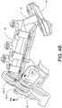
FIG. 4B is a perspective view of a forward engine mount for a turbine engine with the front shackle secured to a turbine engine. -
FIG. 5 is an enlarged perspective view of a shackle interface on airplane left with clevis points on the engine. -
FIG. 6A is a sectional view of a shackle on the airplane right of the engine. -
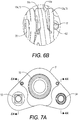
FIG. 6B is an enlarged perspective view of a shackle interface on airplane right with clevis points on the engine. -
FIG. 7A is a front view of the forward shackle assembly of the front engine mount. -
FIG. 7B is a top view of the forward shackle assembly as identified inFIG. 3 . -
FIG. 7C is a perspective of the forward shackle assembly. -
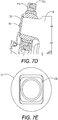
FIG. 7D is a cross sectional view of the forward shackle assembly taken along line. -
FIGS. 7F, 7G, 7H, 7J and7K depict the components of the cylindrical bearing found on airplane right of the forward shackle depicted inFIG. 7A . -
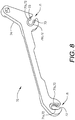
FIG. 8 depicts the wrench washer tool. -
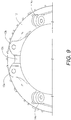
FIG. 9 depicts the forward housing of the engine with the interface attachment points associated with the forward mount. -
FIG. 10 depicts the improved staking configuration for the cylindrical bearing. -
FIG. 11 depicts the detail ofarea 12 depicted inFIG. 11 . -
FIG. 12 depicts the detail of the race staked into the chamfer. -
FIGS. 13-15 depict various load failure points by an -X- and the reacted loads following failure of the indicated fastener or component. - As used herein, the terms "left' and 'right' refer to airplane left and right.
- This disclosure describes an improved fail-safe
engine mounting system 10 suitable for securing turbine engines to aircraft. As depicted inFIG. 1 ,system 10 includes aforward engine mount 20 and anaft engine mount 30 for securing aturbine engine 12 to apylon 5 or other aircraft structure. The securement ofengine 12 topylon 5 viaforward mount 20 and aft mount 30 is accomplished usingmultiple bolts 8 and shear pins 44. Additionally, this disclosure provides an improved bearing staking process suitable for retaining bearing races within any application that requires bearings positioned in a predetermined configuration and substantially precluding rotation of the bearing races. -
Engine 12 includes the necessary securement points for attachment of engine toengine mounting system 10. The forward portion ofengine 12 includes forward mount frontclevis mounting points clevis mounting point 13c. The forward portion ofengine 12 also includes two forward butlower clevis points right clevis point 14a and lower left clevispoint 14b are slightly to the aft of engine forward fail-safeclevis mounting point 13c. As depicted inFIG. 4A , eachclevis mounting point lugs 15 with each lug having a passageway 15a therethrough suitable for receiving bushings 60. - The
forward engine mount 20 will be described with reference toFIGS. 2A-2F ,2H , and3-10 . Theforward engine mount 20 includes amain fitting 40, aforward shackle assembly 50, awhipple tree assembly 80 with twothrust links 87 carried by thewhipple tree 80. Main fitting 40 is a two-piece assembly split along the vertical thrust plane.Bolts 42 passing through mainfitting right 40a and main fitting left 40b and retained by securing devices (not shown) secure each half to the other. Prior to assembly, two or more shear pins 44 having a lower lip orflange 44a are positioned withinrecesses 45 in each half 40a, 40b and are retained therein upon completion of assembly of main fitting right 40a to main fitting left 40b to one another. Eachrecess 45 having agroove 45a which cooperates withflange 44a ofpin 44 to retainshear pin 44 withinmain fitting 40 after assembly thereof. Following assembly of main fittingright half 40a and main fitting left half 40b, recesses 45 defineholes 45 along the centerline ofmain fitting 40. Thus, shear pins 44 are retained withinholes 45 ofmain fitting 40 on the thrust line offorward engine mount 20. - Positioning of shear pins 44 along the centerline of
main fitting 40 ensures application of thrust along the centerline 40c ofmount 20 topylon 5 without inducing any lateral moment. As assembled, oneshear pin 44 is a tight fit having about 0.002 inches (about 0.051 millimeters) clearance betweenpin 44 andmain fitting 40 and asecond shear pin 44 has a slight clearance fit of about 0.01 inches (about 0.25 millimeters) clearance betweenpin 44 andmain fitting 40. Thus, the second shear pin acts as a fail-safe. - In the assembled configuration,
main fitting 40 has a forward projectingboss 46 and a rearward and downward projectingboss 47. Each boss will typically have a tapered decreasing diameter from the main fitting to the end of the boss; however, each boss may have a constant diameter cylinder configuration or any other convenient configuration. Additionally, each boss will have at least two threadedholes 48 with at least onehole 48 in each half of main fitting 40a and 40b. Further, in the assembled configuration,main fitting 40 has a fail-safe lug 49 position on the lower portion ofmain fitting 40. - The
forward shackle assembly 50 includes acoat hanger bracket 51, a center bearing 52, acylindrical bearing 53 and aspherical bearing 54. Positioned withincylindrical bearing 53 is apin 58 with abolt 61 installed withinpin 58.Bolt head 61a is sized to preclude passage throughpin 58; however,bolt head 61a and pin 58 together will pass throughcylindrical bearing 53. Positioned withinspherical bearing 54 is apin 57 with abolt 61 passing throughpin 57.Bolt head 61a is sized to preclude passage throughpin 57; however,bolt head 61a and pin 57 together will pass throughspherical bearing 54. As discussed in more detail below, duringassembly bolt 61 will be positioned withinpin castellated nut 62 secured to bolt 61.Bolt 61 andpin respective bearing Wrench washer 70 will be positioned such thatflanges 73 are located betweenbolt head 61a and pin 57 or 58. Thus,flanges 73 act as a retaining washer. Although described herein aspin 57 andpin 58, the same pin may be used with both bearing assemblies. -
Coat hanger bracket 51 may be a single piece of metal, e.g. steel. However, to provide for the multiple redundancies required by the aviation industry,coat hanger bracket 51 typically includes at least twoseparate elements coat hanger bracket 51. Typically,elements - With reference to
FIG. 7A ,forward shackle assembly 50 includescoat hanger bracket 51 and bearings mounted within coathanger bracket assembly 51. Centrally located withincoat hanger bracket 51 is acenter bearing 52. Center bearing 52 is sized to be fitted over the main fitting forward projectingboss 46. A retention plate positioned over center bearing 52 and secured to forward projectingboss 46 bybolts 56 provides secondary retention offorward shackle assembly 50 tomain fitting 40.Bolts 56 pass throughholes 55a inretention plate 55 and engage threadedholes 48 in forward projectingboss 46. - As further depicted in
FIG. 7A ,cylindrical bearing 53 is positioned to aircraft right of center bearing 52 andspherical bearing 54 is positioned to aircraft left of center bearing 52. However, the side-to-side orientation ofcylindrical bearing 53 andspherical bearing 54 may be reversed and still provide the same functionality. Regardless of the side-to-side orientation of the two bearings,forward shackle assembly 50 provides a statically determinant system betweenforward engine mount 20 and engine forward mount frontclevis mounting points -
Spherical bearing 54 reacts load in both the vertical and lateral direction. Use of a spherical bearing on each side of center bearing 33 could lead to undue stress oncoat hanger bracket 51 and result in load distribution dependent upon the stiffness of theengine 12. With reference toFIG. 5A , to avoid rattle and reduce wear, pin 57 passing throughspherical bearing 54 must have a tight fit withinspherical bearing 54 and engine forward mount frontclevis mounting point 13b. In this application, a tight fight is generally between about 0.0 inches to about 0.002 inches. Thus, use of two spherical bearings will not accommodate thermal expansion between engine forward mount frontclevis mounting points forward shackle assembly 50. As a result, use of two spherical bearings inforward shackle assembly 50 will not provide a statically determinant system. - However, use of
cylindrical bearing 53 at one mounting point offorward shackle assembly 50 provides a loading point that reacts loads only in the vertical direction while permitting angular deflection at engine forward mount frontclevis mounting point 13a. Thus, this configuration provides sufficient lateral clearance to accommodate tolerances. The combination ofspherical bearing 54 andcylindrical bearing 53 provide a statically determinant system. - To ensure the desired loading of
cylindrical bearing 53 in the vertical direction, thecylindrical bearing race 53a ofcylindrical bearing 53 must be staked-inforward shackle assembly 50 such that cylindrical bearinginner member 53b when installed withincylindrical bearing race 53a has lateral clearance but no vertical clearance. As previously noted, the degree of clearance will depend upon the application. As depicted inFIG. 7A , the minimum lateral clearance between cylindrical bearinginner member 53b andrace 53a is about 0.026 inches (about 0.66 millimeters) on each side or total lateral clearance of 0.52 inches (about 13.21 millimeters). The lateral clearance provided bycylindrical bearing 53 permits sliding of cylindrical bearinginner member 53b withincylindrical bearing race 53a. The clearance provided allows the mounting system to accommodate installation tolerances, thermal growth and deflections under normal operating conditions. - Under normal operating conditions, total forces experienced at
forward shackle assembly 50 may be determined with reference tospherical bearing 54. However, in the event of a failure ofspherical bearing 54, the clearances defined above will close due to the added load carried bycylindrical bearing 53 resulting incylindrical bearing 53 reacting both lateral and vertical loads. Thus, after failure ofspherical bearing 53, at least one gap between the parallel exterior walls of cylindrical bearinginner member 53b andrace 53a closes. As illustrated inFIG. 15 , the pin and bolt within fail-safe lug 49 will also engage fail-safeclevis mounting point 13c to only react vertical loads. Likewise, as depicted inFIG. 13 , failure ofcylindrical bearing 53 will transfer all load tospherical bearing 54. Thus, shackle assembly ensures a statically determinant system between engine forward mount frontclevis mounting points bearing FIG. 14 depicts the failure of one-half coat hanger bracket 51. In this failure mode, the surviving portion ofcoat hanger bracket 51 continues to react forces in the same manner as prior to the failure. Thus,cylindrical bearing 53 does not experience any changes in load.FIG. 15 depicts the failure ofcylindrical bearing 53. Under this failure condition, spherical bearing will react all forces of thrust and vertical loads. Additionally, fail-safe lug 49 will engage to only react vertical loads. -
FIGS. 7F-7H and 7J-7K provide further details ofcylindrical bearing 53. As depicted therein,cylindrical bearing 53 includes a cylindrical bearinginner member 53b with flat ends and abearing race 53a.Bearing race 53a has two opposinginterfaces 53c. Cylindrical bearinginner member 53b has two curved exterior walls definingbearing interfaces 53c and two parallel exterior walls. When installed within bearingrace 53a, bearinginterfaces 53c of cylindrical bearinginner member 53bcontact bearing interfaces 53c of bearingrace 53a. In normal operations, interfaces 53c of bearingrace 53a and cylindrical bearinginner member 53b provide the only load contact points between bearingrace 53a and cylindrical bearinginner member 53b. Thus, in this configuration cylindrical bearinginner member 53b slides within bearingrace 53a in the unloaded direction. Additionally, with cylindrical bearinginner member 53b installed withinrace 53a, parallel walls of cylindrical bearinginner member 53b define a gap between cylindrical bearinginner member 53b andrace 53a on each side of cylindrical bearinginner member 53b. Cylindrical bearinginner member 53b is installed by rotating 90° about the cylinder axis relative to the operation position and cylindrical bearinginner member 53b into outercylindrical bearing race 53a. Rotating cylindrical bearinginner member 53b back to the operational position captures cylindrical bearinginner member 53b incylindrical bearing race 53a, i.e. cylindrical bearinginner member 53b engages cylindricalinner interface 53c. Outercylindrical bearing race 53a may optionally include a liner orcylindrical bearing 53 may have metal-to-metal contact betweencylinder 53a and outercylindrical bearing race 53a. - As discussed above,
forward shackle assembly 50 engages engine forward mount frontclevis mounting points clevis passageway 15 of eachclevis point FIGS. 4A ,4B andFIG. 8 , pair flanged bushing 60 is a nested arrangement of an inner-flanged bushing 60a and an outer-flanged bushing 60b. Outer-flanged bushing 60b is press fit within passageway 15a and inner-flanged bushing 60a slid into outer-flanged bushing 60b. This configuration of bushings cooperates withpins bolt 61 and a doublewrench washer tool 70, depicted inFIG. 8 , to permit securement offorward shackle assembly 50 to forward mount frontclevis mounting points flanged bushing 60b material may be 304 annealed CRES, 15-5PH, 17-4PH, H1150 with optionally 100% of all surfaces lubed. Inner-flanged bushing 60a should or could be 15-5PH, 17-4PH, condition H1025 or INCO 718. Typically, the inside diameter and end face of inner-flanged bushing 60a will be lubed at points where it contacts the ball of the bearing. Preferred lubes are moly based or graphite based. Alternatively, outer-flanged bushing 60b may be a bronze material such as Aluminum bronzes, copper beryllium (AMS454 type) or Copper-tin-nickel spinodal bronze (AMS4596 type). When using a bronze material for outer-flanged bushing 60b, inner-flanged bushing 60a will typically be formed from a steel alloy such as 15-5PH. The bronze-based bushing configuration would not require a lubricant. -
FIGS. 4A and6A depict the configuration and relationship of main fitting left 40b offorward shackle assembly 50 positioned withinlugs 15 of engine forward mount frontclevis mounting point 13b. After positioning ofcoat hanger bracket 51 in alignment with engine forward mount frontclevis mounting points pin 58 andbolt 61 are positioned within the assembly by passing from the rear ofcoat hanger bracket 51 throughspherical bearing 54 withincoat hanger bracket 51 and throughclevis mounting point 13b. Likewise, pin 57 andbolt 61 are positioned within the assembly passing from the rear ofcoat hanger bracket 51 throughcylindrical bearing 53 andclevis mounting point 13a. Washers orspacers 75, as needed, are placed onbolts 61 prior to securing a castellated nut or other locking mechanism onbolts 61. As depicted, thehead 61a of eachbolt 61 is sized to pass through the opening of spherical ball 54a and cylindrical bearinginner member 53b. Further as depicted inFIGS. 4A ,5A and 6A ,bolt 61 has a length such that doublewrench washer tool 70 may be positioned betweenpins bolt head 61a withcastellated nut 62 or other locking mechanism secured to eachbolt 61 in the assembled but pre-torqued configuration. - Double
wrench washer tool 70 provides multiple functions within the configuration of fail-safeengine mounting system 10. As depicted inFIG. 8 , doublewrench washer tool 70 has twoslots 71 positioned a distance apart. The distance between slots being equal to the centerline of the clevis mounting point passageways 15a inlugs 15. Each slot having a distance such that theparallel walls wrench flats 72. Additionally,parallel walls flanges 73.Flanges 73 are separated by a distance approximately equal to the diameter ofbolts 61. Thus, when positioned between bolt heads 61a and pins 57, 58, doublewrench washer tool 70 acts both as a wrench withwrench flats 72 engaging bolt heads 61a to preclude rotation thereof during torqueing operations andflanges 73 acting as retaining washers to engage and capture bolt heads 61a. Thus, double wrench washer tool secures and precludes loss ofpins pins wrench washer tool 70 additionally carries atorque application point 74 suitable for engagement by any conventional torque application tool. As depicted inFIG. 8 , the torque application point is an upwardly projectingear 74 with an opening suitable for receiving a drive mechanism.Ear 74 is not limited to an upward projection; rather,torque application point 72 needs to provide sufficient clearance beyond the confines of the equipment being assembled to permit engagement by any conventional torque application tool. - Thus as described above, positioning of
forward shackle assembly 50 withcoat hanger bracket 51 aligned with engine forward mount frontclevis mounting points cylindrical bearing assembly 52 andspherical bearing assembly 54 in alignment with openings 15a of clevis mounting point lugs 15. Final securement ofcoat hanger bracket 51 to clevis mountingpoints bolts 61 throughpins castellated nuts 62 onbolts 61 followed by securingbolt heads 61a with doublewrench washer tool 70. Thewrench flats 72 of doublewrench washer tool 70 are positioned such thatwrench flats 72 andflanges 73 engagebolt heads 61a of eachbolt 61. With doublewrench washer tool 70 positioned between bolt heads 61a and pins 57, 58, eachbolt 61 can be turned until eachhead 61a aligns withwrench flats 72. Once eachbolt head 61a engageswrench flats 72 of doublewrench washer tool 70, then each associatedcastellated nut 62 or other locking mechanism can be tightened to secure forward shackle assembly 50 to engine forward mount frontclevis mounting point - Although described herein as a
castellated nut 62 and cotter pin (not shown) arrangement, the device opposite ofbolt head 61a may be any suitable nut or securement component having at least one secure locking mechanism. In some applications, the securement component will have at least two secure locking mechanisms, e.g. a locking compound and at least one physical locking component. Thus, upon final assembly, doublewrench washer tool 70 remains as an integral component of the joint betweenengine 12 andforward shackle assembly 50. -
FIG. 4A depicts a sectional view of theforward shackle assembly 50 positioned within clevis mountinglugs 15 taken along lines A-A ofFIG. 4B . ThusFIG. 4A depicts a spherical bearing. However, the relationship of thebearings forward shackle assembly 50 positioned within aclevis point FIG. 4A depicts the relationship of engine forward mount frontclevis mounting points bolt 61,spacer 75,castellated nut 62, outer-flanged bushing 60b, i.e. the press fit bushing, inner-flanged bushing 60a and doublewrench washer tool 70. As depicted inFIG. 4A , pins 57 and 58 have aflange 57a, 58a, respectively, positioned at the end of the pin adjacent to the threaded end ofbolt 61. Flange 58a may be omitted and replaced by a large washer orspacer 75 having a diameter sufficient to engage inner- and outer-flanged bushings 61a, 61b. Normally, spherical ball 54a or cylindrical bearinginner member 53b would be positioned between the shoulders ofinner bushings 60a. As discussed above,forward shackle bearings clevis mounting points clevis mounting points bolt head 61a and pin flange 58a force inner-flanged bushing 60a into engagement withspherical ball 10 ofspherical bearing 54 or in the case of thecylindrical bearing 53 into engagement with the cylindrical bearinginner member 53b. Thus, all relative movement takes place between inner- and outer-flanged bushings flanged bushings pins wrench washer 70. If the assembly of a shackle or other bearing mount to a clevis point is not obstructed by other components, a washer orspacer 75 having a diameter sufficient to engage both inner- and out-flanged bushings wrench washer 70. Washer orspacer 75 will be placed betweenbolt head 61a and nested bushing 60. As discussed above, this configuration of nested bushings 60 and spacers orwashers 75 will not place stress on clevis mounting point lugs 15 during torqueing ofnut 62 andbolt 61. - Thus, as depicted in the
FIGS. 3 ,5 and6B , doublewrench washer tool 70 andcastellated nut 62 retainforward shackle assembly 50 within engine forward mount frontclevis mounting points assembly engine 12. Although described herein as a single component, doublewrench washer tool 70 may also be provided as separate individual wrench washers with each having a suitable torque application point. - To complete the assembly of forward engine mount 20 to
engine 12, main fitting fail-safe lug 49 is secured to engine fails-safe clevis 13c. This mounting point does not experience direct engagement unless both bearings incoat hanger bracket 51 fail. Additionally, the thrust links 85 carried bywhipple tree support 80 must be secured to engine forwardlower clevis points - With reference to
FIGS. 2E and2H ,whipple tree support 80 includes three openings, acentral opening 81 and left andright openings Central opening 81 is sized to receive abearing 84 with bearing 84 configured as an interference fit over rearward and downward projectingboss 47. Acap 85 having a diameter greater than opening 81 is positioned over opening 81 withwhipple tree 80 positioned on bearing 84, bolts 86 passing throughcap 85 and intoboss 47 secureswhipple tree 80 toboss 47. As depicted inFIG. 2F , each thrust link 87 is secured towhipple tree 80 by a clamped pin joint arrangement where a pin 88 having an external diameter sized to fit within thrust link opening 87a passes throughwhipple tree opening link 87 towhipple tree 80. Typically, nut 90 for retaining bolt 90 will be a self-locking nut or a castellated nut with cotter pin. Each forward end of thrust links 80 with thrust link opening 87b is positioned within the respective engine forward lower clevispoint lower clevis points point lug 15 will have a bushing 15b positioned within the clevis mounting point passageway 15a. Each forward end of thrust link 80 contains a spherical bearing similar tospherical bearing 54. A pin 88 passes through bushing 15b andspherical bearing 54 with a bolt passing through pin 88 and is retained by a nut 90. Nut 90 may be a self-locking or a castellated nut with cotter pin. - As discussed above,
cylindrical bearing 53 as included withincoat hanger bracket 51 provides a statically determinant system. To provide this system,cylindrical bearing 53 must be arranged such that it carries load only in the vertical direction. Accordingly, rotation of bearing withinforward shackle assembly 50 during assembly offorward shackle assembly 50 forward mount frontclevis mounting points cylindrical bearing 53 withinforward shackle assembly 50,cylindrical bearing race 53a is staked withinforward shackle assembly 50. With reference toFIGS. 10-12 , the staking process includes the steps of forming a staking groove 92 withincylindrical bearing race 53a and machining a matchingchamfer 93 within theopening 94 offorward shackle assembly 50. Following machining ofchamfer 93, one or more spherical ball end mill "divots" 95 are machined intochamfer 93. After positioning ofcylindrical bearing race 53a in opening 94 and conventionally stakingcylindrical bearing race 53a, a second staking step is used. In the second staking step, a ball nosed "punch" or other appropriate staking tool is placed over the race at the location of eachdivot 95 and hammered with sufficient force to drive race material into eachdivot 95. Thus, the second staking step forces the staked bearing to additionally conform withdivot 95 previously machined intochamfer 93. The additional staking step increase the torque restraint value of the staked-in bearing by two to three times the torque restraint value of the conventionally staked-in bearing. For a bearing race located within a two-inch hole, the torque restraint value will increase from about 500 inch-lbf (about 56.6 Newton-meters) for conventional staking to at least 1000 inch-lbf (about 113 Newton-meters) and typically will increase to 1500 inch-lbf (about 169.5 Newton-meters) depending on the metal used for the race of the staked-in bearing. -
FIG. 2G depicts anaft mount 30.Aft mount 30 includes a pylon fitting 31 made up bypylon halves 31a and 31b. Joinder ofhalves 31a and 31b bybolts 32 and pins 33 captures and retains threelinks Links spherical bearings 54 and to rear engine clevis points 16 withspherical bearings 54. As described above, abolt 61 andnut 62 will retainlinks Link 36 is also joined to pylon fitting 31 by staked orientedbearings 38 positioned withinopenings 37. Staked orientedbearings 38 do not carry load along the axis oflinks bearings 38 only carry load perpendicular to the axis running along the length oflinks bearings 38 include the use of a chamfer and divot as described above with regard to orientedcylindrical bearing 53 offorward mount 20. Additionally,aft mount 30 includes at least twoshear pins 44 with eachshear pin 44 having a lower lip orflange 44a. Each shear pin is sandwiched betweenhalves 31a and 31b of pylon fitting 31. Thus, shear pins 44 are located on the centerline ofaft mount 30. Location of shear pins 44 on the centerline ofaft mount 30 ensures lateral loads are carried without inducing moments in that direction. As assembled oneshear pin 44 is a tight fit, about 0.002 inches (about 0.051 millimeters) clearance betweenpin 44 and pylon 31 and asecond shear pin 44 is a slight clearance fit, about 0.01 inches (about 0.25 millimeters) clearance betweenpin 44 and pylon 31. Thus, the second shear pin acts as a fail-safe. - Other embodiments of the present invention will be apparent to one skilled in the art. As such, the foregoing description merely enables and describes the general uses and methods of the present invention. Accordingly, the following claims define the true scope of the present invention.
Claims (11)
- An engine mounting system (10) comprising:a forward engine mount (20) carrying a forward shackle assembly (50), said forward shackle assembly (50) comprises a coat hanger bracket (51), and a center bearing (52) positioned within a first hole passing through said coat hanger bracket (51),characterized in that the system further comprises:a cylindrical bearing (53) positioned within a second hole passing through said coat hanger bracket (51) and a spherical bearing (54) within a third hole passing through said coat hanger bracket (51);a first pin (58) passing through said cylindrical bearing (53);a second pin (57) passing through said spherical bearing (54);a first bolt (61) passing through said first pin (58), said first bolt (61) having a threaded end, said first bolt (61) having a bolt head (61a) sized to permit passage of the bolt head (61a) through said cylindrical bearing (53); anda second bolt (61) passing through said second pin (57), said second bolt (61) having a threaded end, said second bolt (61) having a bolt head (61a) sized to permit passage of the bolt head (61a) through said spherical bearing (54).
- The engine mounting system (10) of claim 1, wherein said forward shackle assembly (50) provides a statically determinant system.
- The engine mounting system (10) of claim 1, wherein said cylindrical bearing (53) carries load only in the vertical direction.
- The engine mounting system (10) of claim 3, further comprising:a chamfer (93) around the circumference of said second hole and at least one divot (95) within the area defined by said chamfer (93);said cylindrical bearing (53) having a race (53a), said race (53a) having upper and lower interfaces (53c) and said race (53a) retained within said second hole by a staking operation between said race (53a) and said chamfer (93);a portion of said race (53a) further deformed into the area defined by said divot (95), thereby securing said race (53a) within said hole; and,a cylindrical bearing cylinder positioned within said race (53a), said cylindrical bearing (53) having upper and lower interfaces (53c) and right and left walls, said cylindrical bearing cylinder engaging only said race upper and lower interfaces (53a) and defining a gap between the right and left walls of said cylindrical bearing (53) cylinder and said race (53a).
- The engine mounting system (10) of claim 1, wherein said forward engine mount (20) further comprises:a split main fitting (40), said split main fitting (40) carrying a forward projecting boss (46) and a rearward and downward projecting boss (47), said forward projecting boss (46) and rearward and downward projecting boss (47) defining the length of said main fitting (40), said main fitting (40) split into two halves (40a, 40b) along the centerline (40c) of said length of said main fitting (40), said forward projecting boss (46) carrying said forward shackle assembly (50);said main fitting halves (40a, 40b) secured to one another,said main fitting (40) having at least one hole (45) positioned on the centerline (40c) of said main fitting (40);a shear pin (44) retained within said hole (45) on the centerline (40c) of said main fitting (40).
- The engine mounting system (10) of claim 5, wherein said main fitting (40) has at least two holes (45) positioned on the centerline (40c) of said main fitting (40), a first shear pin (44) retained within a first hole (45) and a second shear pin (44) retained within a second hole (45), wherein the first shear pin (44) reacts force and the second shear pin (44) reacts force only in the event of the failure of the first shear pin (44).
- The engine mounting system (10) of claim 1, further comprising:an engine (12), wherein said forward engine mount (20) comprises a main fitting (40), said main fitting (40) carrying said forward shackle assembly (50);first and second clevis points (13a, 13b) on said engine (12) each clevis point (13a, 13b) having a pair of lugs (15), said clevis points (13a, 13b) configured to be secured to said cylindrical bearing (53) and said spherical bearing (54) carried by said coat hanger bracket (51);a set of nested bushings (60) positioned within each lug (15) of each clevis point (13a, 13b);wherein said first pin (58) passing through said cylindrical bearing (53) further comprises said nested bushings (60) within said first clevis point (13a);wherein said second pin (57) passing through said spherical bearing (54) further comprises said nested bushing (60) within said second clevis point (13b);wherein said first bolt (61) having a bolt head (61a) sized to permit passage of the bolt head (61a) through said cylindrical bearing (53) but not through said first pin (58) wherein said bolt head (61a) projects outward from said first clevis point (13a);a first securement device positioned on said first bolt (61) opposite of said bolt head (61a);wherein said second bolt (61) having a bolt head (61a) sized to permit passage of the bolt head (61a) through said spherical bearing (54) but not through said second pin (57) wherein said bolt head (61a) projects outward from said second clevis point (13b);a second securement device positioned on said second bolt (61) opposite of said bolt head (61a);a wrench washer tool (70) positioned between said first bolt head (61a) and said nested bushing (60) within said first clevis point (13a) and between said second bolt head (61a) and said nested bushing (60) within said second clevis point (13b).
- The engine mounting system (10) of claim 7, further comprising:a failsafe lug (49) carried by said main fitting (40);a third clevis point (13c) carried by said engine;said failsafe lug (49) aligns with said third clevis point (13c); and,a third pin with a third bolt (61) positioned within said pin, said pin passing through said failsafe lug (49) and said third clevis point (13c).
- The engine mounting system (10) of claim 8, wherein said system (10) provides a statically determinant system.
- The engine mounting system (10) of claim 8, wherein said coat hanger bracket (51) is comprises two halves (51a, 51b) with the first half (51a) being a front element and the second half (51b) being a back element, wherein each half (51a, 51b) houses said center bearing (52), said spherical bearing (54) and said cylindrical bearing (53).
- The engine mounting system (10) of claim 10, wherein upon failure of any one of said spherical bearing (54), said cylindrical bearing (53), said front element or said back element, said engine mounting system (10) provides a statically determinant system.
Applications Claiming Priority (2)
| Application Number | Priority Date | Filing Date | Title |
|---|---|---|---|
| US201562100672P | 2015-01-07 | 2015-01-07 | |
| PCT/US2016/012480 WO2016112187A2 (en) | 2015-01-07 | 2016-01-07 | Aircraft engine mount |
Publications (2)
| Publication Number | Publication Date |
|---|---|
| EP3242834A2 EP3242834A2 (en) | 2017-11-15 |
| EP3242834B1 true EP3242834B1 (en) | 2018-11-28 |
Family
ID=55272645
Family Applications (1)
| Application Number | Title | Priority Date | Filing Date |
|---|---|---|---|
| EP16702238.3A Active EP3242834B1 (en) | 2015-01-07 | 2016-01-07 | Aircraft engine mount |
Country Status (4)
| Country | Link |
|---|---|
| US (2) | US10464685B2 (en) |
| EP (1) | EP3242834B1 (en) |
| CN (2) | CN110182373B (en) |
| WO (1) | WO2016112187A2 (en) |
Cited By (1)
| Publication number | Priority date | Publication date | Assignee | Title |
|---|---|---|---|---|
| US11661967B2 (en) | 2019-04-17 | 2023-05-30 | Raytheon Technologies Corporation | Mounting device and method for mounting components |
Families Citing this family (26)
| Publication number | Priority date | Publication date | Assignee | Title |
|---|---|---|---|---|
| US10464684B2 (en) * | 2016-02-01 | 2019-11-05 | Bell Textron Inc. | Tapered sockets for aircraft engine mount assemblies |
| US20170259929A1 (en) * | 2016-03-10 | 2017-09-14 | General Electric Company | Method and system for mounting an aircraft engine |
| FR3058388B1 (en) * | 2016-11-04 | 2019-05-10 | Airbus Operations | REAR ATTACHMENT OF AN AIRCRAFT ENGINE |
| FR3061480B1 (en) * | 2016-12-30 | 2019-05-31 | Airbus Operations | AIRCRAFT ENGINE ASSEMBLY COMPRISING A FRONT ENGINE ATTACHMENT FACILITATING ITS ASSEMBLY |
| US10723471B2 (en) | 2017-06-14 | 2020-07-28 | General Electric Company | Method and system for mounting an aircraft engine |
| US10689124B2 (en) * | 2017-08-16 | 2020-06-23 | Cedric P. Martin | Adjustable offset mount (AOM) for engines of model airplanes |
| US10814993B2 (en) * | 2017-08-21 | 2020-10-27 | Raytheon Technologies Corporation | Inlet cowl deflection limiting strut |
| US10577976B2 (en) * | 2017-10-30 | 2020-03-03 | United Technologies Corporation | Mounting assembly with rotatable and/or translatable retainer pins |
| FR3075175B1 (en) * | 2017-12-20 | 2019-12-13 | Safran Aircraft Engines | SUSPENSION DEVICE |
| FR3084339A1 (en) * | 2018-07-30 | 2020-01-31 | Airbus Operations | ASSEMBLY FOR AN AIRCRAFT, THE ASSEMBLY COMPRISING A MAT AND A FRONT ENGINE MOUNT |
| FR3086924B1 (en) * | 2018-10-08 | 2021-02-12 | Safran Aircraft Engines | TURBOMACHINE WITH SUSPENSION MEANS |
| FR3086925B1 (en) * | 2018-10-08 | 2020-09-11 | Safran Aircraft Engines | TURBOMACHINE SUSPENSION KIT |
| FR3089954B1 (en) * | 2018-12-12 | 2021-01-08 | Airbus Operations Sas | MOTORIZATION KIT FOR AN AIRCRAFT INCLUDING A LOAD SUPPORT |
| CN109611216B (en) * | 2018-12-16 | 2021-08-17 | 中国航发沈阳发动机研究所 | Gear box hanging device |
| US11479104B2 (en) | 2019-07-24 | 2022-10-25 | Honeywell International Inc. | System and method for gas turbine engine mount with seal |
| FR3102151B1 (en) * | 2019-10-21 | 2021-10-29 | Airbus Operations Sas | Aircraft comprising a rear wing attachment having at least two lateral connecting rods and a shear pin |
| CN110745250B (en) * | 2019-11-22 | 2023-04-18 | 中国航发沈阳黎明航空发动机有限责任公司 | Assembly type mounting structure and mounting method for ignition accessory of aero-engine |
| CN111963562A (en) * | 2020-08-20 | 2020-11-20 | 中国航空工业集团公司沈阳飞机设计研究所 | An ear piece connection structure |
| US11560840B2 (en) | 2020-10-16 | 2023-01-24 | General Electric Company | Damper engine mount links |
| US11821253B2 (en) * | 2020-11-12 | 2023-11-21 | The Boeing Company | Aircraft door common stop fitting |
| US11708169B2 (en) * | 2020-12-14 | 2023-07-25 | Spirit Aerosystems, Inc. | Thrust load reaction assembly |
| US11834159B2 (en) * | 2021-10-18 | 2023-12-05 | Goodrich Corporation | Torque button bushing |
| US11708156B2 (en) * | 2021-10-20 | 2023-07-25 | Textron Innovations Inc. | Friction welded raceways for use in rotorcraft propulsion assemblies |
| US12103692B2 (en) * | 2021-12-20 | 2024-10-01 | Textron Innovations Inc. | Engine truss for aircraft |
| CN115050680B (en) * | 2022-08-16 | 2022-10-28 | 江苏邑文微电子科技有限公司 | Quick positioning device and method for wafer box |
| US12208924B1 (en) | 2022-12-07 | 2025-01-28 | United States Of America As Represented By The Secretary Of The Air Force | Aircraft engine installation alignment system |
Family Cites Families (68)
| Publication number | Priority date | Publication date | Assignee | Title |
|---|---|---|---|---|
| DE1531395A1 (en) * | 1967-07-18 | 1970-01-29 | Entwicklungsring Sued Gmbh | Engine suspension, especially for the jet engines of short or vertical take-off aircraft |
| US3662462A (en) | 1970-02-09 | 1972-05-16 | Rohr Corp | Method of securing a bearing race within a bore in a housing |
| US4055369A (en) | 1975-05-12 | 1977-10-25 | The Boeing Company | Seal for a spherical bearing |
| US4276974A (en) | 1978-03-27 | 1981-07-07 | Federal-Mogul Corp. | Self-aligning clutch release bearing |
| DE2851308C2 (en) | 1978-11-27 | 1987-01-15 | Messerschmitt-Bölkow-Blohm GmbH, 8012 Ottobrunn | Device for mortising bearing bushes |
| US4219246A (en) | 1979-05-14 | 1980-08-26 | Federal-Mogul Corporation | Staked flange clutch release bearing assembly |
| CA1162394A (en) | 1980-12-23 | 1984-02-21 | Incom International Inc. | Method of manufacturing a spherical bearing |
| US4597258A (en) * | 1984-11-26 | 1986-07-01 | United Technologies Corporation | Combustor mount |
| US5351930A (en) * | 1992-08-11 | 1994-10-04 | Lord Corporation | Mounting for engines and the like |
| US5277382A (en) | 1992-10-13 | 1994-01-11 | General Electric Company | Aircraft engine forward mount |
| US5303880A (en) * | 1992-10-28 | 1994-04-19 | General Electric Company | Aircraft engine pin mount |
| US5649417A (en) | 1995-03-24 | 1997-07-22 | The Boeing Company | Fail-safe engine mount system |
| US5860623A (en) * | 1995-05-03 | 1999-01-19 | The Boeing Company | Three link failsafe engine mount |
| CN1076689C (en) * | 1996-08-22 | 2001-12-26 | 波音公司 | Fail-safe engine mount system |
| CN1174799A (en) * | 1996-08-27 | 1998-03-04 | 波音公司 | Three link failsafe engine mount |
| FR2770486B1 (en) * | 1997-11-06 | 2000-01-28 | Aerospatiale | DEVICE FOR HANGING AN ENGINE ON AN AIRCRAFT |
| DE19935469A1 (en) | 1999-07-28 | 2000-05-11 | Skf Gmbh | Method for fixing at least one bearing in bearing endshield with recess for reception of bearing |
| JP2001193734A (en) | 2000-01-05 | 2001-07-17 | Minebea Co Ltd | How to fix spherical plain bearings |
| GB2359332B (en) * | 2000-02-18 | 2003-04-23 | Pudsey Diamond Engineering Ltd | Door locking assemblies, especially for street lighting columns |
| US6330995B1 (en) * | 2000-02-29 | 2001-12-18 | General Electric Company | Aircraft engine mount |
| JP2002213468A (en) | 2001-01-19 | 2002-07-31 | Minebea Co Ltd | Bearing fixing method |
| US6666583B2 (en) | 2001-12-04 | 2003-12-23 | Visteon Global Technologies, Inc. | Bearing retention assembly having cam chamfered bearing race ring |
| US20040108640A1 (en) * | 2002-12-09 | 2004-06-10 | Michael Robert Joseph | Elastomeric bearing assembly and associated pin structure |
| US7093996B2 (en) * | 2003-04-30 | 2006-08-22 | General Electric Company | Methods and apparatus for mounting a gas turbine engine |
| FR2855494B1 (en) * | 2003-05-27 | 2006-09-22 | Snecma Moteurs | AIRCRAFT ENGINE REAR HITCHING DEVICE |
| US20050047696A1 (en) | 2003-08-28 | 2005-03-03 | Serrels Dana M. | Apparatus and method for retaining bearings |
| US6843449B1 (en) | 2004-02-09 | 2005-01-18 | General Electric Company | Fail-safe aircraft engine mounting system |
| FR2867155B1 (en) | 2004-03-08 | 2007-06-29 | Snecma Moteurs | SUSPENSION OF AN ENGINE TO THE STRUCTURE OF AN AIRCRAFT |
| FR2883256B1 (en) | 2005-03-18 | 2008-10-24 | Airbus France Sas | ENGINE ATTACHMENT OF A MOUNTING SYSTEM INTERPOSED BETWEEN A COUPLING MACHINE AND AN AIRCRAFT ENGINE |
| US7628019B2 (en) | 2005-03-21 | 2009-12-08 | United Technologies Corporation | Fuel injector bearing plate assembly and swirler assembly |
| FR2883839B1 (en) * | 2005-03-29 | 2007-06-29 | Snecma Moteurs Sa | REAR SUSPENSION OF TURBOREACTOR |
| FR2887851B1 (en) * | 2005-06-29 | 2007-08-17 | Airbus France Sas | ENGINE ATTACHING MAT FOR AN AIRCRAFT |
| FR2887853B1 (en) * | 2005-06-29 | 2007-08-17 | Airbus France Sas | ENGINE ATTACHMENT FOR AN AIRCRAFT INTENDED TO BE INTERPOSED BETWEEN A MOTOR AND A COUPLING MAT |
| FR2891245B1 (en) * | 2005-09-26 | 2007-10-26 | Airbus France Sas | METHOD FOR MOUNTING AN AIRCRAFT ENGINE ON A RIGID STRUCTURE OF A MOTOR ATTACHMENT MAT |
| FR2891243B1 (en) * | 2005-09-26 | 2009-04-03 | Airbus France Sas | ENGINE ATTACHING MAT FOR AN AIRCRAFT |
| FR2891253B1 (en) | 2005-09-28 | 2007-10-26 | Airbus France Sas | REAR ATTACHMENT OF A TWO-SHOWN AIRCRAFT ENGINE |
| FR2894934B1 (en) * | 2005-12-15 | 2009-11-13 | Airbus France | REAR AXLE ATTACHMENT OF AN AIRCRAFT ENGINE WITH MANILITY WAITING FOR AND SPRING FOR SUCH AN AXIS WAITING |
| GB0603539D0 (en) | 2006-02-22 | 2006-04-05 | Airbus Uk Ltd | Control surface failsafe drop link |
| US20070223849A1 (en) | 2006-03-21 | 2007-09-27 | Roller Bearing Company Of America, Inc. | Spherical plain bearing and a housing in combination with a spherical plain bearing |
| FR2901243B1 (en) * | 2006-05-16 | 2008-06-27 | Airbus France Sas | DEVICE FOR HITCHING AN AIRCRAFT ENGINE |
| US7810239B2 (en) | 2006-10-23 | 2010-10-12 | United Technologies Corporation | Engine mount bearing sleeve repair |
| FR2916424B1 (en) * | 2007-05-23 | 2009-08-21 | Airbus France Sa | AIRCRAFT ENGINE ATTACHING MACHINE COMPRISING A BIAISE SHIM FOR ATTACHING THE FRONT ENGINE ATTACHMENT |
| FR2917713B1 (en) * | 2007-06-21 | 2009-09-25 | Airbus France Sas | APPARATUS FOR ATTACHING AN AIRCRAFT ENGINE AND AIRCRAFT HAVING AT LEAST ONE SUCH DEVICE. |
| FR2920138B1 (en) * | 2007-08-24 | 2010-03-12 | Airbus France | AIRCRAFT ENGINE HANDLING DEVICE HAVING A REDUCED GAPPING EFFORTS RECOVERY DEVICE |
| GB2452938B (en) * | 2007-09-19 | 2011-08-10 | Messier Dowty Ltd | Load indicator |
| GB0810585D0 (en) | 2008-06-11 | 2008-07-16 | Rolls Royce Plc | Engine mounting arrangement |
| FR2965549B1 (en) * | 2010-10-01 | 2013-07-05 | Airbus Operations Sas | ROPE RESTRAINT DEVICE FOR AN AIRCRAFT ENGINE HITCHING MACHINE, INTEGRATING THREE ALIGNED ROTORS |
| FR2974065B1 (en) * | 2011-04-14 | 2013-05-10 | Snecma | METHOD FOR MOUNTING AN AIRCRAFT ENGINE ON A PYLONE AND ENGINE ATTACHMENT FOR THE IMPLEMENTATION OF SUCH A METHOD |
| US8870533B2 (en) | 2011-07-13 | 2014-10-28 | General Electric Company | Assembly for aligning an inner shell of a turbine casing |
| US20130042630A1 (en) | 2011-08-19 | 2013-02-21 | United Technologies Corporation | Gas turbine engine accessory mount |
| US8851417B2 (en) * | 2012-08-07 | 2014-10-07 | United Technologies Corporation | Self-retaining shear pin for blind mount location |
| US20140084129A1 (en) * | 2012-09-27 | 2014-03-27 | United Technologies Corporation | Assembly for mounting a turbine engine case to a pylon |
| FR3000529B1 (en) * | 2012-12-28 | 2015-03-06 | Airbus Operations Sas | FLEXIBLE BONDING DEVICE FOR AN AIRCRAFT PROPULSIVE ASSEMBLY |
| CN103112595B (en) * | 2013-02-06 | 2016-01-27 | 中国商用飞机有限责任公司 | Propulsion system integrated suspension structure |
| CN103101628B (en) * | 2013-02-06 | 2015-05-27 | 中国商用飞机有限责任公司 | Front mounting joint integrated with airplane hanging |
| US9033297B2 (en) * | 2013-06-04 | 2015-05-19 | Hamilton Sundstrand Corporation | Cabin air compressor support bracket |
| US9248921B2 (en) * | 2013-07-11 | 2016-02-02 | Spirit Aerosystems, Inc. | Method for mounting a pylon to an aircraft |
| FR3014841B1 (en) * | 2013-12-17 | 2017-12-08 | Airbus Operations Sas | AIRCRAFT ASSEMBLY COMPRISING A PART ATTACHED ENGINE BODY MADE OF A SINGLE PIECE WITH AN INNER RIB OF A RIGIDIFICATION OF A HOUSING MAT SUBSTATION |
| FR3014840B1 (en) * | 2013-12-17 | 2017-10-13 | Airbus Operations Sas | AIRCRAFT ASSEMBLY COMPRISING A MOTOR ATTACHING BODY EQUIPPED WITH AT LEAST ONE MANILITY SUPPORT BRACKET PENETRATING IN THE HOUSING OF THE ATTACHING MAT |
| GB201417202D0 (en) * | 2014-09-30 | 2014-11-12 | Rolls Royce Plc | Gas Turbine Engine Mounting Arrangement |
| FR3027875A1 (en) * | 2014-10-30 | 2016-05-06 | Airbus Operations Sas | DEVICE FOR FIXING AN AIRCRAFT ENGINE, AND A CORRESPONDING AIRCRAFT |
| US10119563B2 (en) * | 2015-04-04 | 2018-11-06 | The Boeing Company | Offset bushing and method of use |
| FR3040369B1 (en) * | 2015-09-02 | 2018-07-13 | Airbus Operations Sas | AIRCRAFT ENGINE ASSEMBLY COMPRISING AN IMPROVED FRONT ENGINE ATTACHMENT |
| EP3455128A1 (en) * | 2016-05-13 | 2019-03-20 | LORD Corporation | Isolator devices, systems and methods for aircraft |
| US10875655B2 (en) * | 2017-06-23 | 2020-12-29 | Hutchinson Aerospace & Industry Inc. | Vibration isolation device, especially for aircraft applications |
| US10358227B2 (en) * | 2017-08-15 | 2019-07-23 | The Boeing Company | Sideload reaction bearing |
| US11167842B2 (en) * | 2017-10-10 | 2021-11-09 | Bell Helicopter Textron Inc. | Mount for supporting a component and attenuating noise |
| US10597144B2 (en) * | 2017-12-01 | 2020-03-24 | Hadie Fotouhie | Under the wing-mounted jet engine with pivotal swivel joint to produce directional thrust vectoring thru swivel angle |
-
2016
- 2016-01-07 EP EP16702238.3A patent/EP3242834B1/en active Active
- 2016-01-07 US US15/533,196 patent/US10464685B2/en active Active
- 2016-01-07 WO PCT/US2016/012480 patent/WO2016112187A2/en not_active Ceased
- 2016-01-07 CN CN201910284113.1A patent/CN110182373B/en active Active
- 2016-01-07 CN CN201680005239.5A patent/CN107108039B/en active Active
-
2019
- 2019-06-03 US US16/429,218 patent/US10752370B2/en active Active
Non-Patent Citations (1)
| Title |
|---|
| None * |
Cited By (1)
| Publication number | Priority date | Publication date | Assignee | Title |
|---|---|---|---|---|
| US11661967B2 (en) | 2019-04-17 | 2023-05-30 | Raytheon Technologies Corporation | Mounting device and method for mounting components |
Also Published As
| Publication number | Publication date |
|---|---|
| US20190092484A1 (en) | 2019-03-28 |
| US10752370B2 (en) | 2020-08-25 |
| WO2016112187A3 (en) | 2016-09-09 |
| EP3242834A2 (en) | 2017-11-15 |
| CN107108039A (en) | 2017-08-29 |
| CN110182373A (en) | 2019-08-30 |
| CN110182373B (en) | 2023-01-10 |
| CN107108039B (en) | 2019-08-30 |
| US10464685B2 (en) | 2019-11-05 |
| WO2016112187A2 (en) | 2016-07-14 |
| US20190352013A1 (en) | 2019-11-21 |
Similar Documents
| Publication | Publication Date | Title |
|---|---|---|
| US10752370B2 (en) | Aircraft engine mount | |
| US8348191B2 (en) | Fail-safe aircraft engine mounting apparatus | |
| US11338929B2 (en) | Forward engine attachment system for an aircraft engine comprising a direct coupling between the jet engine pylon and the engine | |
| US8985509B2 (en) | Assembly for mounting a turbine engine to a pylon | |
| US11905025B2 (en) | Mounting system for aircraft engine | |
| US8083177B2 (en) | Means for preventing the rotation of a pin supporting a turbine engine suspension member | |
| US11975856B2 (en) | Front engine attachment system for an aircraft engine, comprising a more a lightweight structure | |
| EP2109720B1 (en) | Self-retaining anti-rotation clip and spherical-bearing rod end comprising such a clip | |
| US10577114B2 (en) | Assembly for an aircraft engine mounting comprising an articulation axis supported by a yoke joint and translationally immobile | |
| JP6885756B2 (en) | Damage Tolerance Fail Safe (DTFS) High Strength Preload Pin Assembly | |
| US11273923B2 (en) | Fail-safe engine support system | |
| EP2921727B1 (en) | U-shaped clip for fixing a link rod within an aircraft clevis | |
| JP2001336520A (en) | Aircraft engine mount | |
| EP3011634B1 (en) | Universal adapter plate assembly | |
| US6350060B1 (en) | Dual load path spherical bearing and a method of coupling along a dual load path | |
| US11518533B2 (en) | Front engine attachment system for an aircraft engine, having a beam made in three parts | |
| US8104709B2 (en) | Lateral force joint | |
| US11015698B2 (en) | Gearbox mounting link | |
| EP3263933B1 (en) | Countersunk threaded bearing and method of installation | |
| US11066860B1 (en) | Hinged assembly with fail-safe hinge pin | |
| CN111511644B (en) | Suspension device | |
| US11535389B2 (en) | Front engine attachment system for an aircraft engine, having a beam made in two parts | |
| US11518531B2 (en) | Aircraft engine attachment comprising at least one system for immobilizing a shear pin in translation comprising a stop plate, method for mounting said engine attachment and aircraft comprising said engine attachment | |
| US20220185491A1 (en) | Thrust load reaction assembly | |
| US20250304271A1 (en) | Aircraft engine attachment system comprising a two-point shackle equipped with at least one stop, aircraft comprising at least one such engine attachment system |
Legal Events
| Date | Code | Title | Description |
|---|---|---|---|
| STAA | Information on the status of an ep patent application or granted ep patent |
Free format text: STATUS: THE INTERNATIONAL PUBLICATION HAS BEEN MADE |
|
| PUAI | Public reference made under article 153(3) epc to a published international application that has entered the european phase |
Free format text: ORIGINAL CODE: 0009012 |
|
| STAA | Information on the status of an ep patent application or granted ep patent |
Free format text: STATUS: REQUEST FOR EXAMINATION WAS MADE |
|
| 17P | Request for examination filed |
Effective date: 20170605 |
|
| AK | Designated contracting states |
Kind code of ref document: A2 Designated state(s): AL AT BE BG CH CY CZ DE DK EE ES FI FR GB GR HR HU IE IS IT LI LT LU LV MC MK MT NL NO PL PT RO RS SE SI SK SM TR |
|
| AX | Request for extension of the european patent |
Extension state: BA ME |
|
| DAV | Request for validation of the european patent (deleted) | ||
| DAX | Request for extension of the european patent (deleted) | ||
| GRAP | Despatch of communication of intention to grant a patent |
Free format text: ORIGINAL CODE: EPIDOSNIGR1 |
|
| STAA | Information on the status of an ep patent application or granted ep patent |
Free format text: STATUS: GRANT OF PATENT IS INTENDED |
|
| INTG | Intention to grant announced |
Effective date: 20180524 |
|
| GRAJ | Information related to disapproval of communication of intention to grant by the applicant or resumption of examination proceedings by the epo deleted |
Free format text: ORIGINAL CODE: EPIDOSDIGR1 |
|
| STAA | Information on the status of an ep patent application or granted ep patent |
Free format text: STATUS: REQUEST FOR EXAMINATION WAS MADE |
|
| GRAR | Information related to intention to grant a patent recorded |
Free format text: ORIGINAL CODE: EPIDOSNIGR71 |
|
| GRAS | Grant fee paid |
Free format text: ORIGINAL CODE: EPIDOSNIGR3 |
|
| STAA | Information on the status of an ep patent application or granted ep patent |
Free format text: STATUS: GRANT OF PATENT IS INTENDED |
|
| INTC | Intention to grant announced (deleted) | ||
| GRAA | (expected) grant |
Free format text: ORIGINAL CODE: 0009210 |
|
| STAA | Information on the status of an ep patent application or granted ep patent |
Free format text: STATUS: THE PATENT HAS BEEN GRANTED |
|
| INTG | Intention to grant announced |
Effective date: 20181011 |
|
| AK | Designated contracting states |
Kind code of ref document: B1 Designated state(s): AL AT BE BG CH CY CZ DE DK EE ES FI FR GB GR HR HU IE IS IT LI LT LU LV MC MK MT NL NO PL PT RO RS SE SI SK SM TR |
|
| REG | Reference to a national code |
Ref country code: CH Ref legal event code: EP |
|
| REG | Reference to a national code |
Ref country code: AT Ref legal event code: REF Ref document number: 1069941 Country of ref document: AT Kind code of ref document: T Effective date: 20181215 |
|
| REG | Reference to a national code |
Ref country code: IE Ref legal event code: FG4D |
|
| REG | Reference to a national code |
Ref country code: DE Ref legal event code: R096 Ref document number: 602016007605 Country of ref document: DE |
|
| REG | Reference to a national code |
Ref country code: NL Ref legal event code: MP Effective date: 20181128 |
|
| REG | Reference to a national code |
Ref country code: LT Ref legal event code: MG4D |
|
| REG | Reference to a national code |
Ref country code: AT Ref legal event code: MK05 Ref document number: 1069941 Country of ref document: AT Kind code of ref document: T Effective date: 20181128 |
|
| PG25 | Lapsed in a contracting state [announced via postgrant information from national office to epo] |
Ref country code: AT Free format text: LAPSE BECAUSE OF FAILURE TO SUBMIT A TRANSLATION OF THE DESCRIPTION OR TO PAY THE FEE WITHIN THE PRESCRIBED TIME-LIMIT Effective date: 20181128 Ref country code: LV Free format text: LAPSE BECAUSE OF FAILURE TO SUBMIT A TRANSLATION OF THE DESCRIPTION OR TO PAY THE FEE WITHIN THE PRESCRIBED TIME-LIMIT Effective date: 20181128 Ref country code: NO Free format text: LAPSE BECAUSE OF FAILURE TO SUBMIT A TRANSLATION OF THE DESCRIPTION OR TO PAY THE FEE WITHIN THE PRESCRIBED TIME-LIMIT Effective date: 20190228 Ref country code: LT Free format text: LAPSE BECAUSE OF FAILURE TO SUBMIT A TRANSLATION OF THE DESCRIPTION OR TO PAY THE FEE WITHIN THE PRESCRIBED TIME-LIMIT Effective date: 20181128 Ref country code: HR Free format text: LAPSE BECAUSE OF FAILURE TO SUBMIT A TRANSLATION OF THE DESCRIPTION OR TO PAY THE FEE WITHIN THE PRESCRIBED TIME-LIMIT Effective date: 20181128 Ref country code: ES Free format text: LAPSE BECAUSE OF FAILURE TO SUBMIT A TRANSLATION OF THE DESCRIPTION OR TO PAY THE FEE WITHIN THE PRESCRIBED TIME-LIMIT Effective date: 20181128 Ref country code: BG Free format text: LAPSE BECAUSE OF FAILURE TO SUBMIT A TRANSLATION OF THE DESCRIPTION OR TO PAY THE FEE WITHIN THE PRESCRIBED TIME-LIMIT Effective date: 20190228 Ref country code: FI Free format text: LAPSE BECAUSE OF FAILURE TO SUBMIT A TRANSLATION OF THE DESCRIPTION OR TO PAY THE FEE WITHIN THE PRESCRIBED TIME-LIMIT Effective date: 20181128 Ref country code: IS Free format text: LAPSE BECAUSE OF FAILURE TO SUBMIT A TRANSLATION OF THE DESCRIPTION OR TO PAY THE FEE WITHIN THE PRESCRIBED TIME-LIMIT Effective date: 20190328 |
|
| PG25 | Lapsed in a contracting state [announced via postgrant information from national office to epo] |
Ref country code: SE Free format text: LAPSE BECAUSE OF FAILURE TO SUBMIT A TRANSLATION OF THE DESCRIPTION OR TO PAY THE FEE WITHIN THE PRESCRIBED TIME-LIMIT Effective date: 20181128 Ref country code: GR Free format text: LAPSE BECAUSE OF FAILURE TO SUBMIT A TRANSLATION OF THE DESCRIPTION OR TO PAY THE FEE WITHIN THE PRESCRIBED TIME-LIMIT Effective date: 20190301 Ref country code: RS Free format text: LAPSE BECAUSE OF FAILURE TO SUBMIT A TRANSLATION OF THE DESCRIPTION OR TO PAY THE FEE WITHIN THE PRESCRIBED TIME-LIMIT Effective date: 20181128 Ref country code: PT Free format text: LAPSE BECAUSE OF FAILURE TO SUBMIT A TRANSLATION OF THE DESCRIPTION OR TO PAY THE FEE WITHIN THE PRESCRIBED TIME-LIMIT Effective date: 20190328 Ref country code: AL Free format text: LAPSE BECAUSE OF FAILURE TO SUBMIT A TRANSLATION OF THE DESCRIPTION OR TO PAY THE FEE WITHIN THE PRESCRIBED TIME-LIMIT Effective date: 20181128 |
|
| PG25 | Lapsed in a contracting state [announced via postgrant information from national office to epo] |
Ref country code: NL Free format text: LAPSE BECAUSE OF FAILURE TO SUBMIT A TRANSLATION OF THE DESCRIPTION OR TO PAY THE FEE WITHIN THE PRESCRIBED TIME-LIMIT Effective date: 20181128 |
|
| PG25 | Lapsed in a contracting state [announced via postgrant information from national office to epo] |
Ref country code: DK Free format text: LAPSE BECAUSE OF FAILURE TO SUBMIT A TRANSLATION OF THE DESCRIPTION OR TO PAY THE FEE WITHIN THE PRESCRIBED TIME-LIMIT Effective date: 20181128 Ref country code: CZ Free format text: LAPSE BECAUSE OF FAILURE TO SUBMIT A TRANSLATION OF THE DESCRIPTION OR TO PAY THE FEE WITHIN THE PRESCRIBED TIME-LIMIT Effective date: 20181128 Ref country code: PL Free format text: LAPSE BECAUSE OF FAILURE TO SUBMIT A TRANSLATION OF THE DESCRIPTION OR TO PAY THE FEE WITHIN THE PRESCRIBED TIME-LIMIT Effective date: 20181128 |
|
| REG | Reference to a national code |
Ref country code: DE Ref legal event code: R097 Ref document number: 602016007605 Country of ref document: DE |
|
| PG25 | Lapsed in a contracting state [announced via postgrant information from national office to epo] |
Ref country code: SK Free format text: LAPSE BECAUSE OF FAILURE TO SUBMIT A TRANSLATION OF THE DESCRIPTION OR TO PAY THE FEE WITHIN THE PRESCRIBED TIME-LIMIT Effective date: 20181128 Ref country code: RO Free format text: LAPSE BECAUSE OF FAILURE TO SUBMIT A TRANSLATION OF THE DESCRIPTION OR TO PAY THE FEE WITHIN THE PRESCRIBED TIME-LIMIT Effective date: 20181128 Ref country code: MC Free format text: LAPSE BECAUSE OF FAILURE TO SUBMIT A TRANSLATION OF THE DESCRIPTION OR TO PAY THE FEE WITHIN THE PRESCRIBED TIME-LIMIT Effective date: 20181128 Ref country code: EE Free format text: LAPSE BECAUSE OF FAILURE TO SUBMIT A TRANSLATION OF THE DESCRIPTION OR TO PAY THE FEE WITHIN THE PRESCRIBED TIME-LIMIT Effective date: 20181128 Ref country code: SM Free format text: LAPSE BECAUSE OF FAILURE TO SUBMIT A TRANSLATION OF THE DESCRIPTION OR TO PAY THE FEE WITHIN THE PRESCRIBED TIME-LIMIT Effective date: 20181128 |
|
| REG | Reference to a national code |
Ref country code: CH Ref legal event code: PL |
|
| PG25 | Lapsed in a contracting state [announced via postgrant information from national office to epo] |
Ref country code: LU Free format text: LAPSE BECAUSE OF NON-PAYMENT OF DUE FEES Effective date: 20190107 |
|
| PLBE | No opposition filed within time limit |
Free format text: ORIGINAL CODE: 0009261 |
|
| STAA | Information on the status of an ep patent application or granted ep patent |
Free format text: STATUS: NO OPPOSITION FILED WITHIN TIME LIMIT |
|
| REG | Reference to a national code |
Ref country code: BE Ref legal event code: MM Effective date: 20190131 |
|
| REG | Reference to a national code |
Ref country code: IE Ref legal event code: MM4A |
|
| PG25 | Lapsed in a contracting state [announced via postgrant information from national office to epo] |
Ref country code: SI Free format text: LAPSE BECAUSE OF FAILURE TO SUBMIT A TRANSLATION OF THE DESCRIPTION OR TO PAY THE FEE WITHIN THE PRESCRIBED TIME-LIMIT Effective date: 20181128 |
|
| 26N | No opposition filed |
Effective date: 20190829 |
|
| PG25 | Lapsed in a contracting state [announced via postgrant information from national office to epo] |
Ref country code: BE Free format text: LAPSE BECAUSE OF NON-PAYMENT OF DUE FEES Effective date: 20190131 |
|
| PG25 | Lapsed in a contracting state [announced via postgrant information from national office to epo] |
Ref country code: CH Free format text: LAPSE BECAUSE OF NON-PAYMENT OF DUE FEES Effective date: 20190131 Ref country code: LI Free format text: LAPSE BECAUSE OF NON-PAYMENT OF DUE FEES Effective date: 20190131 |
|
| PG25 | Lapsed in a contracting state [announced via postgrant information from national office to epo] |
Ref country code: IE Free format text: LAPSE BECAUSE OF NON-PAYMENT OF DUE FEES Effective date: 20190107 |
|
| PG25 | Lapsed in a contracting state [announced via postgrant information from national office to epo] |
Ref country code: TR Free format text: LAPSE BECAUSE OF FAILURE TO SUBMIT A TRANSLATION OF THE DESCRIPTION OR TO PAY THE FEE WITHIN THE PRESCRIBED TIME-LIMIT Effective date: 20181128 |
|
| PG25 | Lapsed in a contracting state [announced via postgrant information from national office to epo] |
Ref country code: MT Free format text: LAPSE BECAUSE OF NON-PAYMENT OF DUE FEES Effective date: 20190107 |
|
| PG25 | Lapsed in a contracting state [announced via postgrant information from national office to epo] |
Ref country code: CY Free format text: LAPSE BECAUSE OF FAILURE TO SUBMIT A TRANSLATION OF THE DESCRIPTION OR TO PAY THE FEE WITHIN THE PRESCRIBED TIME-LIMIT Effective date: 20181128 |
|
| PG25 | Lapsed in a contracting state [announced via postgrant information from national office to epo] |
Ref country code: HU Free format text: LAPSE BECAUSE OF FAILURE TO SUBMIT A TRANSLATION OF THE DESCRIPTION OR TO PAY THE FEE WITHIN THE PRESCRIBED TIME-LIMIT; INVALID AB INITIO Effective date: 20160107 |
|
| PG25 | Lapsed in a contracting state [announced via postgrant information from national office to epo] |
Ref country code: MK Free format text: LAPSE BECAUSE OF FAILURE TO SUBMIT A TRANSLATION OF THE DESCRIPTION OR TO PAY THE FEE WITHIN THE PRESCRIBED TIME-LIMIT Effective date: 20181128 |
|
| PGFP | Annual fee paid to national office [announced via postgrant information from national office to epo] |
Ref country code: GB Payment date: 20230127 Year of fee payment: 8 |
|
| P01 | Opt-out of the competence of the unified patent court (upc) registered |
Effective date: 20230524 |
|
| REG | Reference to a national code |
Ref country code: DE Ref legal event code: R079 Ref document number: 602016007605 Country of ref document: DE Free format text: PREVIOUS MAIN CLASS: B64D0027260000 Ipc: B64D0027400000 |
|
| PGFP | Annual fee paid to national office [announced via postgrant information from national office to epo] |
Ref country code: IT Payment date: 20240122 Year of fee payment: 9 |
|
| GBPC | Gb: european patent ceased through non-payment of renewal fee |
Effective date: 20240107 |
|
| PG25 | Lapsed in a contracting state [announced via postgrant information from national office to epo] |
Ref country code: GB Free format text: LAPSE BECAUSE OF NON-PAYMENT OF DUE FEES Effective date: 20240107 |
|
| PG25 | Lapsed in a contracting state [announced via postgrant information from national office to epo] |
Ref country code: GB Free format text: LAPSE BECAUSE OF NON-PAYMENT OF DUE FEES Effective date: 20240107 |
|
| PGFP | Annual fee paid to national office [announced via postgrant information from national office to epo] |
Ref country code: DE Payment date: 20250129 Year of fee payment: 10 |
|
| PG25 | Lapsed in a contracting state [announced via postgrant information from national office to epo] |
Ref country code: IT Free format text: LAPSE BECAUSE OF NON-PAYMENT OF DUE FEES Effective date: 20250107 |
|
| PGFP | Annual fee paid to national office [announced via postgrant information from national office to epo] |
Ref country code: FR Payment date: 20260126 Year of fee payment: 11 |