EP3242750B1 - Manual pipette with selectable plunger force - Google Patents
Manual pipette with selectable plunger force Download PDFInfo
- Publication number
- EP3242750B1 EP3242750B1 EP16711887.6A EP16711887A EP3242750B1 EP 3242750 B1 EP3242750 B1 EP 3242750B1 EP 16711887 A EP16711887 A EP 16711887A EP 3242750 B1 EP3242750 B1 EP 3242750B1
- Authority
- EP
- European Patent Office
- Prior art keywords
- spring
- manual pipette
- plunger
- handle portion
- pipette
- Prior art date
- Legal status (The legal status is an assumption and is not a legal conclusion. Google has not performed a legal analysis and makes no representation as to the accuracy of the status listed.)
- Active
Links
Images





Classifications
-
- B—PERFORMING OPERATIONS; TRANSPORTING
- B01—PHYSICAL OR CHEMICAL PROCESSES OR APPARATUS IN GENERAL
- B01L—CHEMICAL OR PHYSICAL LABORATORY APPARATUS FOR GENERAL USE
- B01L3/00—Containers or dishes for laboratory use, e.g. laboratory glassware; Droppers
- B01L3/02—Burettes; Pipettes
- B01L3/021—Pipettes, i.e. with only one conduit for withdrawing and redistributing liquids
- B01L3/0217—Pipettes, i.e. with only one conduit for withdrawing and redistributing liquids of the plunger pump type
-
- B—PERFORMING OPERATIONS; TRANSPORTING
- B01—PHYSICAL OR CHEMICAL PROCESSES OR APPARATUS IN GENERAL
- B01L—CHEMICAL OR PHYSICAL LABORATORY APPARATUS FOR GENERAL USE
- B01L3/00—Containers or dishes for laboratory use, e.g. laboratory glassware; Droppers
- B01L3/02—Burettes; Pipettes
- B01L3/021—Pipettes, i.e. with only one conduit for withdrawing and redistributing liquids
- B01L3/0217—Pipettes, i.e. with only one conduit for withdrawing and redistributing liquids of the plunger pump type
- B01L3/0224—Pipettes, i.e. with only one conduit for withdrawing and redistributing liquids of the plunger pump type having mechanical means to set stroke length, e.g. movable stops
-
- B—PERFORMING OPERATIONS; TRANSPORTING
- B01—PHYSICAL OR CHEMICAL PROCESSES OR APPARATUS IN GENERAL
- B01L—CHEMICAL OR PHYSICAL LABORATORY APPARATUS FOR GENERAL USE
- B01L2200/00—Solutions for specific problems relating to chemical or physical laboratory apparatus
- B01L2200/02—Adapting objects or devices to another
- B01L2200/028—Modular arrangements
-
- B—PERFORMING OPERATIONS; TRANSPORTING
- B01—PHYSICAL OR CHEMICAL PROCESSES OR APPARATUS IN GENERAL
- B01L—CHEMICAL OR PHYSICAL LABORATORY APPARATUS FOR GENERAL USE
- B01L2200/00—Solutions for specific problems relating to chemical or physical laboratory apparatus
- B01L2200/06—Fluid handling related problems
-
- B—PERFORMING OPERATIONS; TRANSPORTING
- B01—PHYSICAL OR CHEMICAL PROCESSES OR APPARATUS IN GENERAL
- B01L—CHEMICAL OR PHYSICAL LABORATORY APPARATUS FOR GENERAL USE
- B01L2200/00—Solutions for specific problems relating to chemical or physical laboratory apparatus
- B01L2200/08—Ergonomic or safety aspects of handling devices
- B01L2200/087—Ergonomic aspects
Definitions
- the invention pertains to manual pipettes having a thumb-actuated plunger.
- Most conventional manual pipettes have a plunger button on the top of the handle.
- the plunger button is depressed by the user's thumb to manually lower a plunger shaft which in turn lowers a pipetting piston.
- a disposable pipette tip is mounted on a fitting attached to the lower portion of the pipettor.
- the seal around the pipetting piston causes suction in the disposable pipette tip when the piston is retracted.
- a piston return spring causes the piston to retract thereby causing suction within the pipette tip to aspirate the liquid into the tip.
- Most manual pipettes also include a blowout spring mechanism that enables the plunger to move downward past the natural fully depressed range for aspiration in order to blow out residual liquid when dispensing from the tip.
- the piston spring return force is normally selected by the manufacturer to be as light as possible, yet sufficient to reliably overcome friction associated with the piston seal arrangement and possibly additional friction associated with the return of the piston and plunger to the home position. In some cases, however, such a light spring force is not desirable. For example, when pipetting viscous fluids one may require greater spring return forces in order to ensure accurate and efficient liquid transfer. As another example, some users may find a pipette with a higher return spring force to be more ergonomic or comfortable to use even with non-viscous fluids.
- the invention in D1 ( US2012039768 ) relates to a nozzle assembly for mounting in a pipette, which comprises a two-piece body consisting of a nozzle 3 and a holder 2.
- the movement of only the plunger 1 is responsible for the drawing up and discharge mechanism in the pipette.
- the plunger 1 itself is driven by the pipetting rod 18 arranged in a pipette handle 16.
- D2 ( GB2161398 ) claims a pipette which comprises of a handle 1 with a volume-adjusting means and interchangeable heads 26.
- Each head 26 has a different number of pipette channels and each head 26 is capable of being assembled with the handle 1.
- the head 26 is releasably connected to the handle 1 by means of a connector 30 which for example is provided with hook-shaped flanges 31.
- the connector 30 is always a part of the head 26 and for example can be snap-fitted into recesses 32 present in the handle 1.
- the pipetting device according to D3 ( US2005155438 ) consists of a displacement device and a drive device.
- the displacement device includes the displaceable limiter, an attachment for connecting to a pipette tip and a connection channel between the displacement chamber and the free end of the attachment.
- the drive device mainly includes the drive member which again is driving the displaceable limiter.
- a releasable bayonet connection is established between the displacement device and the drive device by producing the cooperation between the drive member and the displacement limiter.
- the invention provides a convenient, reliable technique for replacing the piston return spring with another piston return spring having, for example, a different spring force.
- the invention is directed to a manual pipette comprising an upper handle portion and a lower portion that is detachable from the upper handle portion.
- the lower portion includes a fitting for a disposable pipette tip.
- a removable plunger spring assembly is mounted within the pipettor, preferably within the upper handle portion, and can be removed or replaced when the lower portion is detached from the upper handle portion.
- the removable plunger spring assembly includes an upper piston shaft, a piston return spring and a coupling, such as a magnet or a mechanical coupling, fixed to the lower end of the upper piston shaft.
- the upper plunger spring assembly also includes a spring retaining base through which the lower end of the upper piston shaft is able to slide.
- the upper piston shaft passes through the middle of the piston return spring.
- the upper piston shaft includes a lubricious bearing surface, e.g., a dry layer of polytetrafluoroethylene.
- An upper spring retainer is mounted at top or near the top of the piston shaft and holds the spring in compression between the upper spring retainer and the spring retaining base.
- a pipetting piston is located in the lower portion and is operatively coupled to the coupling on the upper piston shaft when the lower portion is attached to the upper handle portion and the manual pipette is assembled for operation.
- the upper handle portion includes a threaded sleeve secured to its lower end, and the spring retaining base includes mating threads.
- the plunger spring assembly is mounted into the upper handle portion by fastening the spring retaining base of the plunger spring assembly to the threaded sleeve of the upper handle portion.
- the lower portion includes a threaded collar at its upper end that is attached to the upper handle portion to assemble the manual pipette for operation by fastening the threaded collar to the threaded sleeve on the upper handle portion as well.
- the manual pipette can be provided as a kit with a piston return spring having a light spring force, one having an intermediate spring force, and another having a heavy spring force.
- the components of the plunger spring assembly including the piston return spring are connected together as a unit, and are mounted into the upper handle portion and removed from the upper handle portion as a unit. Such a configuration enables the entire plunger spring assembly to be replaced with another plunger spring assembly having a piston return spring with a different spring return force.
- the various plunger spring assemblies can be made visually distinguishable if desirable, e.g., using a label or a color-coded spring retaining base.
- An installation tool is provided, optionally, to facilitate the attachment and detachment of the spring retaining base of the plunger spring assembly to the manual pipettor.
- Figures 1 through 5 illustrate a manual pipette 10 that is constructed in accordance with an exemplary embodiment of the invention.
- the manual pipette 10 includes an upper handle portion 12 and a lower portion 14 that is detachable from the upper handle portion 12.
- the lower portion 14 includes a tip fitting 16 at its distal end.
- a disposable pipette tip is mounted to the tip fitting 16 in order to aspirate liquid into the pipette tip for liquid transfer.
- aspects of the invention can be implemented in manual pipettes that do not enable the use of disposable tips, such as syringe-based manual pipettes.
- the lower portion 14 includes a threaded collar 18 at its top end which is fastened to a threaded sleeve 60, Fig. 3 , located at the lower end 30 of the upper handle portion 12 in order to attach the lower portion 14 to the upper handle portion 12.
- the upper handle portion 12 is grasped by the hand of a user.
- the user depresses plunger button 20 with their thumb to move the plunger shaft 22 downward against spring force, and releases the plunger button 20 to retract the plunger shaft 22 and aspirate liquid into a pipette tip mounted onto the fitting 16. Liquid is dispensed from the pipette tip by depressing the plunger button 20.
- a tip ejector button 28 is also located on the handle, as well as a volume adjustment mechanism 34.
- Fig. 2a shows a plunger spring assembly 36 removed from the upper handle portion 12 of the pipette 10.
- the plunger spring assembly 36 includes an upper piston shaft 38, a piston return spring 40, a spring retaining base 42, an upper spring retainer 50, Fig. 4 , and a magnet 44.
- the magnet 44 is secured to the lower end of the upper piston shaft 38, for example with adhesive.
- the upper piston shaft 38 is able to slide through the spring retaining base 42, but the diameter of the magnet 44 is sufficient to hold the spring retaining base 42 on the plunger spring assembly 36.
- Fig. 2a also shows an installation tool 46 having a pair of upstanding protrusions 48. The protrusions 48 fit into an installation interface 54 (such as teeth), Fig.
- Fig. 2b shows the installation tool 46 in use. Note that the lower portion 14, Fig. 1 , must be removed in order for the installation tool 46 to access the threaded base 42 on the plunger spring assembly 36. While the embodiment illustrated in the drawings shows the plunger spring assembly 36 removeably mounted to the upper handle portion 12 of the pipette 10, it is contemplated that the plunger spring assembly 36 could be removeably mounted to the lower portion 14 of the pipette 10.
- Fig. 4 illustrates the components of the exemplary plunger spring assembly 36.
- the upper piston shaft 38 preferably passes through the center of the piston return spring 40.
- the upper piston shaft 38 can be made of any suitable material including for example stainless steel or aluminum.
- the piston return spring 40 likewise can be made of any suitable material including for example stainless steel.
- the top end of the upper piston shaft 38 includes a circumferential recess 52 in which a spring retainer 50 is fixed.
- the spring retainer 50 desirably comprises dual half shells that are connected together around the piston shaft 38 within the recess 52.
- the lower end of the upper piston shaft 38 passes through a central bore 43 in the spring retaining base 42.
- the magnet 44 is secured to lower end of the upper piston shaft 38 via adhesive, and holds the spring retaining base 42 on the plunger spring assembly 36.
- the spring 40 is loaded in compression between the spring retainer 50 and the spring retaining base 42.
- Figs. 5 and 6 illustrate a modified embodiment of the plunger spring assembly 36.
- the upper piston shaft 38 in Figs. 5 and 6 includes a surface 39 made of lubricious material, such as a layer of heat shrink polytetrafluoroethylene.
- the lubricious surface 39 helps to smooth the interaction between the shaft 38 and the spring 40 when the pipette is in operation.
- lubrication can be used, but a dry lubricious surface avoids the need to handle a component with messy lubrication.
- the plunger spring assembly 36 in Figs. 5 and 6 is also modified to incorporate a cone-shaped crown 41, which facilitates alignment with the plunger shaft 22, especially when reassembling the pipette.
- Fig. 3 illustrates a longitudinal cross-section view of the manual pipette 10 fully assembled.
- Pipette tip fitting 16 at the distal end of the lower portion 14 is in fluid communication with piston 56.
- the top portion 58 of the piston 56 is magnetically attached to the magnet 44 on the plunger spring assembly 36 that is mounted within the upper handle portion 12.
- An O-ring 70 and PTFE (polytetrafluoroethylene) seal 71 are secured around the piston 56.
- the O-ring 70 provides a static seal with the cylinder body.
- the PTFE seal 71 provides a dynamic seal against the piston 56.
- the O-ring 70 and PTFE seal 71 are held in place by spring 72 and sleeve 73 as the piston 56 extends and retracts. Retraction causes suction in a disposable pipette tip mounted on the tip fitting 16.
- the plunger shaft 22 extending downward from the plunger button 20 interfaces with the top of the upper piston shaft 38.
- the plunger shaft 22 includes a stop 62 that physically interacts with a volume adjustment mechanism 34, which together cooperate to set the overall aspiration range of motion of the plunger 22, upper piston shaft 38 and piston 56. Stop 62 on the plunger shaft 22 resides in an area within the upper handle portion 12 that provides clearance for volume adjustment.
- the plunger shaft 22 pushes downward on the upper piston shaft 38 which in turn pushes downward on the piston 56.
- the spring 40 compresses between the spring retainer 50 on the top of the upper piston shaft 38 and the top of the spring retaining base 42.
- FIG 3 shows the upper piston shaft 38 moved partially downward through the spring retaining base 42, and consequently the spring 40 is in partial compression.
- the spring force is normally selected by the manufacturer as mentioned to overcome the friction force associated with the O-ring 70/PTFE seal 71 against the piston 56 as well as any other frictional forces along the piston, upper piston shaft 38, and plunger shaft 22.
- the plunger spring assembly 36 is conveniently removable to facilitate replacement of the spring 40 or, alternatively, the entire plunger spring assembly 36. Replacement can be made to repair the pipette or to change the strength of the spring 40.
- the upper handle portion 12 includes as mentioned a threaded sleeve 60 secured to the lower end 30 of the upper handle portion 12.
- the spring retaining base 42 has mating threads that fasten to the threaded sleeve 60, e.g., using the installation tool 46 shown in Figs.
- the threaded collar 18 on the lower portion 14 is attached to the upper handle portion 12 by fastening the threaded collar 18 to the threaded sleeve 60 as well.
- the spring retaining base 42 can be accessed for removal once the lower portion 14 is removed.
- the user presses the plunger 20 downward to release the suction caused by the retracted piston 56.
- the user pushes downward on the plunger 20 beyond its normal full aspiration position, as is known in the art, to blow out residual liquid in the pipette tip.
- the blowout sleeve 24 includes a stop 68 that is normally biased upwards by spring 66.
- the upper piston shaft 38 and piston 56 are pushed further downward to facilitate blowout.
- the manual pipette 10 may be provided to the end user as a kit with two or three (or more) plunger spring assemblies 36A, 36B and 36C.
- Each plunger spring assembly 36A, 36B, 36C in Fig. 5 preferably has a spring 40A, 40B, 40C providing a different spring return force.
- spring 40A may provide a light return force
- spring 40C may provide a heavy return force
- spring 40B may provide an intermediate return force.
- the spring force level for springs 40A, 40B, 40C can be pre-selected by the manufacturer, or can be specified by the customer.
- the spring retaining bases 42A, 42B, 42C may be color coded or labeled so that the user can easily determine which spring 40A, 40B, 40C is being installed or used.
- the kit can be provided with one plunger spring assembly 36 but with multiple springs.
- Fig. 10 illustrates an alternative tool 90 for removing the plunger spring assemblies 40A, 40B, and 40C shown in Fig, 5 .
- the tool 90 includes protrusion 92 to engage the installation surface 54 on the spring retaining base 42; however, the tool 90 is a three-in-one tool. It also provides a calibration fitting 94, and a fitting 96 to install and remove o-ring seals.
Landscapes
- Health & Medical Sciences (AREA)
- Clinical Laboratory Science (AREA)
- Chemical & Material Sciences (AREA)
- Chemical Kinetics & Catalysis (AREA)
- Devices For Use In Laboratory Experiments (AREA)
Description
- The invention pertains to manual pipettes having a thumb-actuated plunger.
- Most conventional manual pipettes have a plunger button on the top of the handle. The plunger button is depressed by the user's thumb to manually lower a plunger shaft which in turn lowers a pipetting piston. A disposable pipette tip is mounted on a fitting attached to the lower portion of the pipettor. The seal around the pipetting piston causes suction in the disposable pipette tip when the piston is retracted. To aspirate liquid into the disposable pipette tip, the end of the tip is submerged in the liquid and, the user releases the plunger. A piston return spring causes the piston to retract thereby causing suction within the pipette tip to aspirate the liquid into the tip. The user then moves the pipette to a dispensing location and again depresses the plunger against the force of the spring in order to dispense the liquid from the pipette tip. Most manual pipettes also include a blowout spring mechanism that enables the plunger to move downward past the natural fully depressed range for aspiration in order to blow out residual liquid when dispensing from the tip.
- The piston spring return force is normally selected by the manufacturer to be as light as possible, yet sufficient to reliably overcome friction associated with the piston seal arrangement and possibly additional friction associated with the return of the piston and plunger to the home position. In some cases, however, such a light spring force is not desirable. For example, when pipetting viscous fluids one may require greater spring return forces in order to ensure accurate and efficient liquid transfer. As another example, some users may find a pipette with a higher return spring force to be more ergonomic or comfortable to use even with non-viscous fluids.
The invention in D1 (US2012039768 ) relates to a nozzle assembly for mounting in a pipette, which comprises a two-piece body consisting of a nozzle 3 and a holder 2. The movement of only the plunger 1 is responsible for the drawing up and discharge mechanism in the pipette. The plunger 1 itself is driven by thepipetting rod 18 arranged in apipette handle 16. There is apressure sleeve 6 placed in the holder 2 wherein the plunger 1 is slidably borne in thepressure sleeve 6 for ensuring leakproofness of the plunger. Between thepressure sleeve 6 and the nozzle 3 there are the sealing means comprising of a gasket 5 and a sealing ring 4.
D2 (GB2161398 interchangeable heads 26. Eachhead 26 has a different number of pipette channels and eachhead 26 is capable of being assembled with the handle 1. Thehead 26 is releasably connected to the handle 1 by means of aconnector 30 which for example is provided with hook-shaped flanges 31. Theconnector 30 is always a part of thehead 26 and for example can be snap-fitted intorecesses 32 present in the handle 1.
The pipetting device according to D3 (US2005155438 ) consists of a displacement device and a drive device. The displacement device includes the displaceable limiter, an attachment for connecting to a pipette tip and a connection channel between the displacement chamber and the free end of the attachment. The drive device mainly includes the drive member which again is driving the displaceable limiter. A releasable bayonet connection is established between the displacement device and the drive device by producing the cooperation between the drive member and the displacement limiter. - The invention provides a convenient, reliable technique for replacing the piston return spring with another piston return spring having, for example, a different spring force.
- The invention is directed to a manual pipette comprising an upper handle portion and a lower portion that is detachable from the upper handle portion. In the exemplary embodiments shown in the drawings, the lower portion includes a fitting for a disposable pipette tip. Aspects of the invention can however be implemented in manual pipettes that do not enable the use of disposable tips. A removable plunger spring assembly is mounted within the pipettor, preferably within the upper handle portion, and can be removed or replaced when the lower portion is detached from the upper handle portion. The removable plunger spring assembly includes an upper piston shaft, a piston return spring and a coupling, such as a magnet or a mechanical coupling, fixed to the lower end of the upper piston shaft. The upper plunger spring assembly also includes a spring retaining base through which the lower end of the upper piston shaft is able to slide. The upper piston shaft passes through the middle of the piston return spring. In one embodiment, the upper piston shaft includes a lubricious bearing surface, e.g., a dry layer of polytetrafluoroethylene. An upper spring retainer is mounted at top or near the top of the piston shaft and holds the spring in compression between the upper spring retainer and the spring retaining base. A pipetting piston is located in the lower portion and is operatively coupled to the coupling on the upper piston shaft when the lower portion is attached to the upper handle portion and the manual pipette is assembled for operation. In the exemplary embodiments, the upper handle portion includes a threaded sleeve secured to its lower end, and the spring retaining base includes mating threads. The plunger spring assembly is mounted into the upper handle portion by fastening the spring retaining base of the plunger spring assembly to the threaded sleeve of the upper handle portion. The lower portion includes a threaded collar at its upper end that is attached to the upper handle portion to assemble the manual pipette for operation by fastening the threaded collar to the threaded sleeve on the upper handle portion as well.
- The above described configuration facilitates convenient, reliable replacement of the piston return spring and in turn enables the user to select the force required to depress the plunger. For example, in accordance with the invention, the manual pipette can be provided as a kit with a piston return spring having a light spring force, one having an intermediate spring force, and another having a heavy spring force. Desirably, the components of the plunger spring assembly including the piston return spring are connected together as a unit, and are mounted into the upper handle portion and removed from the upper handle portion as a unit. Such a configuration enables the entire plunger spring assembly to be replaced with another plunger spring assembly having a piston return spring with a different spring return force. The various plunger spring assemblies can be made visually distinguishable if desirable, e.g., using a label or a color-coded spring retaining base. An installation tool is provided, optionally, to facilitate the attachment and detachment of the spring retaining base of the plunger spring assembly to the manual pipettor.
- Other features and advantages of the invention may be apparent to those skilled in the art upon reviewing the following drawings and description thereof.
-
-
Fig. 1 is a perspective view of a single-channel, manual pipette constructed in accordance with an exemplary embodiment of the invention. -
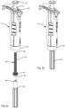
Figs. 2a and 2b illustrate the use of an installation tool to install a plunger spring assembly constructed in accordance with the invention into an upper handle portion of the pipette shown inFig. 1 . -
Fig. 3 is a longitudinal sectional view of the pipette illustrated inFig. 1 . -
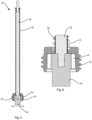
Fig. 4 is a detailed view of a plunger spring assembly constructed in accordance with a exemplary embodiment of the invention. -
Fig. 5 is a detailed view of a plunger spring assembly constructed in accordance with another exemplary embodiment of the invention. -
Fig. 6 is an enlarged view of the region identified by arrow 6-6 inFig. 5 . -
Fig. 7 a detailed view showing the plunger spring assembly inFigs. 5 and 6 fit into theplunger shaft 22 of the pipette. -
Fig. 8 is an enlarged view of the region identified by arrow 8-8 inFig. 7 .. -
Fig. 9 is a view illustrating various components of a manual pipette kit provided with multiple plunger spring assemblies each providing a different spring return force. -
Fig. 10 illustrates an alternative tool for removing the plunger spring assembly, and also for accomplishing other tasks as well. -
Figures 1 through 5 illustrate amanual pipette 10 that is constructed in accordance with an exemplary embodiment of the invention. Referring in particular toFig. 1 , themanual pipette 10 includes anupper handle portion 12 and alower portion 14 that is detachable from theupper handle portion 12. Thelower portion 14 includes a tip fitting 16 at its distal end. A disposable pipette tip, not shown, is mounted to the tip fitting 16 in order to aspirate liquid into the pipette tip for liquid transfer. As noted previously, aspects of the invention can be implemented in manual pipettes that do not enable the use of disposable tips, such as syringe-based manual pipettes. Thelower portion 14 includes a threadedcollar 18 at its top end which is fastened to a threadedsleeve 60,Fig. 3 , located at thelower end 30 of theupper handle portion 12 in order to attach thelower portion 14 to theupper handle portion 12. In use, theupper handle portion 12 is grasped by the hand of a user. The user depressesplunger button 20 with their thumb to move theplunger shaft 22 downward against spring force, and releases theplunger button 20 to retract theplunger shaft 22 and aspirate liquid into a pipette tip mounted onto the fitting 16. Liquid is dispensed from the pipette tip by depressing theplunger button 20. Atip ejector button 28 is also located on the handle, as well as avolume adjustment mechanism 34. -
Fig. 2a shows aplunger spring assembly 36 removed from theupper handle portion 12 of thepipette 10. Theplunger spring assembly 36 includes anupper piston shaft 38, apiston return spring 40, aspring retaining base 42, anupper spring retainer 50,Fig. 4 , and amagnet 44. Themagnet 44 is secured to the lower end of theupper piston shaft 38, for example with adhesive. Theupper piston shaft 38 is able to slide through thespring retaining base 42, but the diameter of themagnet 44 is sufficient to hold thespring retaining base 42 on theplunger spring assembly 36.Fig. 2a also shows aninstallation tool 46 having a pair ofupstanding protrusions 48. Theprotrusions 48 fit into an installation interface 54 (such as teeth),Fig. 4 , on thespring retaining base 42, and provide means for attaching and/or detaching theplunger spring assembly 36 to the threadedsleeve 60,Fig. 3 , located at thelower end 30 of theupper handle portion 12.Fig. 2b shows theinstallation tool 46 in use. Note that thelower portion 14,Fig. 1 , must be removed in order for theinstallation tool 46 to access the threadedbase 42 on theplunger spring assembly 36. While the embodiment illustrated in the drawings shows theplunger spring assembly 36 removeably mounted to theupper handle portion 12 of thepipette 10, it is contemplated that theplunger spring assembly 36 could be removeably mounted to thelower portion 14 of thepipette 10. -
Fig. 4 illustrates the components of the exemplaryplunger spring assembly 36. Theupper piston shaft 38 preferably passes through the center of thepiston return spring 40. Theupper piston shaft 38 can be made of any suitable material including for example stainless steel or aluminum. Thepiston return spring 40 likewise can be made of any suitable material including for example stainless steel. The top end of theupper piston shaft 38 includes acircumferential recess 52 in which aspring retainer 50 is fixed. Thespring retainer 50 desirably comprises dual half shells that are connected together around thepiston shaft 38 within therecess 52. As mentioned, the lower end of theupper piston shaft 38 passes through acentral bore 43 in thespring retaining base 42. Themagnet 44 is secured to lower end of theupper piston shaft 38 via adhesive, and holds thespring retaining base 42 on theplunger spring assembly 36. Thespring 40 is loaded in compression between thespring retainer 50 and thespring retaining base 42. -
Figs. 5 and 6 illustrate a modified embodiment of theplunger spring assembly 36. Theupper piston shaft 38 inFigs. 5 and 6 includes asurface 39 made of lubricious material, such as a layer of heat shrink polytetrafluoroethylene. Thelubricious surface 39 helps to smooth the interaction between theshaft 38 and thespring 40 when the pipette is in operation. Alternatively, lubrication can be used, but a dry lubricious surface avoids the need to handle a component with messy lubrication. Referring toFigs. 6 and7 , theplunger spring assembly 36 inFigs. 5 and 6 is also modified to incorporate a cone-shapedcrown 41, which facilitates alignment with theplunger shaft 22, especially when reassembling the pipette. -
Fig. 3 illustrates a longitudinal cross-section view of themanual pipette 10 fully assembled. Pipette tip fitting 16 at the distal end of thelower portion 14 is in fluid communication withpiston 56. Thetop portion 58 of thepiston 56 is magnetically attached to themagnet 44 on theplunger spring assembly 36 that is mounted within theupper handle portion 12. An O-ring 70 and PTFE (polytetrafluoroethylene)seal 71 are secured around thepiston 56. The O-ring 70 provides a static seal with the cylinder body. ThePTFE seal 71 provides a dynamic seal against thepiston 56. The O-ring 70 andPTFE seal 71 are held in place byspring 72 and sleeve 73 as thepiston 56 extends and retracts. Retraction causes suction in a disposable pipette tip mounted on the tip fitting 16. - The
plunger shaft 22 extending downward from theplunger button 20 interfaces with the top of theupper piston shaft 38. Theplunger shaft 22 includes astop 62 that physically interacts with avolume adjustment mechanism 34, which together cooperate to set the overall aspiration range of motion of theplunger 22,upper piston shaft 38 andpiston 56. Stop 62 on theplunger shaft 22 resides in an area within theupper handle portion 12 that provides clearance for volume adjustment. As the user depresses theplunger button 20 downward, theplunger shaft 22 pushes downward on theupper piston shaft 38 which in turn pushes downward on thepiston 56. As theplunger button 20 is pushed downward, thespring 40 compresses between thespring retainer 50 on the top of theupper piston shaft 38 and the top of thespring retaining base 42.Fig. 3 shows theupper piston shaft 38 moved partially downward through thespring retaining base 42, and consequently thespring 40 is in partial compression. Once theplunger button 20 is fully depressed, and theupper piston shaft 38 andpiston 56 are pushed down to a full aspiration position, the user places the distal end of the disposable pipette tip (not shown) in the liquid and releases theplunger button 20. As the user releases theplunger button 20, thepiston return spring 40 pushes theupper piston shaft 38 upward and pulls thepiston 56 upward via themagnet 44. The upward motion of thepiston 56 causes suction within the disposable pipette tip mounted on the tip fitting 16 to aspirate liquid into the tip. - The spring force is normally selected by the manufacturer as mentioned to overcome the friction force associated with the O-
ring 70/PTFE seal 71 against thepiston 56 as well as any other frictional forces along the piston,upper piston shaft 38, andplunger shaft 22. In accordance with the invention, however, theplunger spring assembly 36 is conveniently removable to facilitate replacement of thespring 40 or, alternatively, the entireplunger spring assembly 36. Replacement can be made to repair the pipette or to change the strength of thespring 40. Theupper handle portion 12 includes as mentioned a threadedsleeve 60 secured to thelower end 30 of theupper handle portion 12. Thespring retaining base 42 has mating threads that fasten to the threadedsleeve 60, e.g., using theinstallation tool 46 shown inFigs. 2a and 2b . The threadedcollar 18 on thelower portion 14 is attached to theupper handle portion 12 by fastening the threadedcollar 18 to the threadedsleeve 60 as well. Thespring retaining base 42 can be accessed for removal once thelower portion 14 is removed. - In order to dispense liquid from a disposable pipette tip mounted on the tip fitting 16, the user presses the
plunger 20 downward to release the suction caused by the retractedpiston 56. To fully complete dispensing, the user pushes downward on theplunger 20 beyond its normal full aspiration position, as is known in the art, to blow out residual liquid in the pipette tip. As theplunger button 20 is pushed downward into thedepression 26 in the top of theupper handle portion 12, theplunger button 20 engagesblowout sleeve 24. Theblowout sleeve 24 includes astop 68 that is normally biased upwards byspring 66. However, when the user continues to push theplunger button 20 downward against theblowout sleeve 24 and the resistance of the blow outspring 66, theupper piston shaft 38 andpiston 56 are pushed further downward to facilitate blowout. - Referring to now
Fig. 9 , it is contemplated that themanual pipette 10 may be provided to the end user as a kit with two or three (or more)plunger spring assemblies plunger spring assembly Fig. 5 preferably has aspring spring 40C may provide a heavy return force andspring 40B may provide an intermediate return force. The spring force level forsprings spring retaining bases plunger spring assembly 36 but with multiple springs. -
Fig. 10 illustrates analternative tool 90 for removing theplunger spring assemblies Fig, 5 . Like thetool 46 shown inFigs. 2 and5 , thetool 90 includesprotrusion 92 to engage theinstallation surface 54 on thespring retaining base 42; however, thetool 90 is a three-in-one tool. It also provides acalibration fitting 94, and a fitting 96 to install and remove o-ring seals. - While the embodiments of the invention shown in the drawings is a single-channel, manual pipette, those skilled in the art will appreciate that the invention can be applied to multi-channel, manual pipettes as well.
- In the foregoing description, certain terms have been used for brevity, clarity, and understanding. No unnecessary limitations are to be inferred therefrom beyond the requirement of the prior art because such terms are used for descriptive purposes and are intended to be broadly construed. The different configurations, systems, and method steps described herein may be used alone or in combination with other configurations, systems and method steps. It is to be expected that various equivalents, alternatives and modifications are possible within the scope of the appended claims.
Claims (15)
- A manual pipette (10) comprising:an upper handle portion (12) and a lower portion (14), said lower portion (14) being detachable from the upper handle portion (12);a plunger (20, 22) on the upper handle portion (12), the plunger having a plunger shaft (22) that interfaces with a top end of the upper piston shaft (38);a plunger spring assembly (36) including at least an upper piston shaft (38), a piston return spring (40), a spring retaining base (42) through which the lower end of the upper piston shaft (38) is able to slide, and a coupling (44) fixed to a lower end of the upper piston shaft (38), characterized in thatsaid plunger spring assembly (36) forms a removable unit where the return spring (40) is compressed between an upper spring retainer (50) secured to the upper piston shaft (38) near its upper end and the spring retaining base (42), andsaid plunger spring assembly (36) being adapted to be mounted within the manual pipette (10) as a unit and removed from the manual pipette (10) as a unit from below by removeably fastening the spring retaining base (42) to the manual pipette (10) when the lower portion (14) is detached from the upper hand portion (12); anda pipetting piston (56) located in the lower portion (14), said pipetting piston (56) operatively coupled to the coupling (44) fixed to the lower end of the upper piston shaft (38) when the plunger spring assembly (36) is installed, the lower portion (14) is attached to the upper handle portion (12) and the manual pipette (10) is assembled for operation.
- A manual pipette as recited in claim 1 wherein the manual pipette is a multi-channel pipette comprising in the lower portion a main piston drive shaft that attaches to and detaches from the coupling fixed to a lower end of the upper piston shaft, a piston drive bar and multiple pipetting pistons.
- A manual pipette as recited in claim 1 wherein the coupling fixed to a lower end of the upper piston shaft is a magnet (44); and
the manual pipette (10) is a single channel pipette and the pipetting piston (56) is magnetically coupled to the magnet fixed to the lower end of the upper piston shaft (38) when the lower portion (14) is attached to the upper handle portion (12) and the manual pipette is assembled for operation. - A manual pipette as recited in claim 1 wherein the upper piston shaft comprises a dry lubricious surface layer (39), preferably comprising a layer of heat shrink polytetrafluoroethylene.
- A manual pipette as recited in claim 1 wherein the plunger spring assembly (36) is mounted into the upper handle portion (12) by fastening the spring retaining base (42) to a lower end of the upper handle portion (12).
- A manual pipette as recited in claim 1 wherein:the upper handle portion (12) includes a threaded sleeve (60) secured at its lower end; andthe spring retaining base (42) includes mating threads, wherein said plunger spring assembly (36) is capable of being mounted to the upper handle portion (12) by fastening the mating threads of the spring retaining base (36) to the threaded sleeve (60) secured to the lower end of the upper handle portion (12).
- A manual pipette as recited in claim 6 wherein the lower portion (14) of the manual pipette has a threaded collar (18) at its upper end and the lower portion (14) is attached to the upper handle portion (12) to assemble the manual pipette (10) for operation by fastening the threaded collar (18) on the lower portion (14) to the threaded sleeve (60) on the upper handle portion (12).
- A manual pipette as recited in claim 1 wherein the spring retaining base (42) on the plunger spring assembly (36) includes an installation interface (54) for engaging an installation tool to attach or detach the spring retaining base from the manual pipette when the lower portion is detached from the upper handle portion.
- The manual pipette as recited in claim 1 further comprising a fitting (16) on the lower portion for a disposable pipette tip.
- The manual pipette recited in claim 1 wherein the recited piston return spring (40, 40A) is a first piston return spring, and the manual pipette is part of a kit further comprising a second piston return spring (40B or 40C), the second piston return spring (40B or 40C) having a spring force that is heavier than the spring force of the first piston return spring (40, 40A),
the manual pipette further comprising a second plunger spring assembly (36B) removeably mounted within the manual pipette and removable when the lower portion is detached from the upper handle portion, the second plunger spring assembly including at least a second upper piston shaft, the second piston return spring (40B), a second spring retaining base (42B) through which the lower end of the second upper piston shaft is able to slide, a second upper spring retainer secured to the second upper piston shaft near its upper end such that the second piston return spring is compressed between the second upper spring retainer and the second spring retaining base, and a second coupling fixed to a lower end of the second upper piston shaft, wherein said second plunger spring assembly is removeably mounted within the manual pipette by removeably fastening the second spring retaining base to the manual pipettor.. - The manual pipette as recited in claim 10 wherein the upper handle portion (12) comprises a threaded sleeve (60) secured its lower end, and the first (42A) and second retaining bases (42B) including mating threads, wherein each of the first (36A) and second plunger spring assemblies (36B) are capable of being mounted to the upper handle portion (12) by fastening the mating threads of the respective spring retaining base (36A, 36B) to the threaded sleeve (60) secured to the lower end of the upper handle portion (12); and the lower portion (14) of the manual pipette has a threaded collar at its upper end and the lower portion is attached to the upper handle portion to assemble the manual pipette for operation by fastening the threaded collar on the lower portion to the threaded sleeve on the upper handle portion.
- The manual pipette as recited in claim 1 wherein the spring retaining base has a central bore through which the lower end of the upper piston shaft is able to slide and the spring retaining base is held on the plunger spring assembly when it is removed from the manual pipette, and
further wherein the coupling(44) fixed to the lower end of the upper piston shaft (38) moves in unison with the lower end of the upper piston shaft (38), is located below the spring retaining base (42) and holds the spring retaining base (42) to the plunger spring assembly (36) when the plunger spring assembly (36) is removed from the manual pipette. - The manual pipette as recited in any of claims 1 to 12 wherein a top of the upper piston shaft includes a cone-shaped crown (41).
- The manual pipette as recited in any of claims 1 to 13 wherein the coupling (44) at the lower end of the upper piston shaft (38) is fixed by adhesive.
- A kit comprising a manual pipette as recited in any of claims 1 to 14 characterized by a tool (90) for removing the plunger spring assemblies (36A, 36B, 36C) and comprising a protrusion (92) to engage the installation surface (54) on the spring retaining base (42).
Applications Claiming Priority (2)
| Application Number | Priority Date | Filing Date | Title |
|---|---|---|---|
| US201562101038P | 2015-01-08 | 2015-01-08 | |
| PCT/IB2016/000108 WO2016110784A1 (en) | 2015-01-08 | 2016-01-06 | Manual pipette with selectable plunger force |
Publications (3)
| Publication Number | Publication Date |
|---|---|
| EP3242750A1 EP3242750A1 (en) | 2017-11-15 |
| EP3242750B1 true EP3242750B1 (en) | 2023-08-30 |
| EP3242750C0 EP3242750C0 (en) | 2023-08-30 |
Family
ID=55629059
Family Applications (1)
| Application Number | Title | Priority Date | Filing Date |
|---|---|---|---|
| EP16711887.6A Active EP3242750B1 (en) | 2015-01-08 | 2016-01-06 | Manual pipette with selectable plunger force |
Country Status (4)
| Country | Link |
|---|---|
| US (1) | US10016755B2 (en) |
| EP (1) | EP3242750B1 (en) |
| JP (1) | JP2018502706A (en) |
| WO (1) | WO2016110784A1 (en) |
Families Citing this family (9)
| Publication number | Priority date | Publication date | Assignee | Title |
|---|---|---|---|---|
| FR3040896B1 (en) * | 2015-09-15 | 2017-10-13 | Gilson Sas | PRESSURE PIPETTE COMPRISING A DOUBLE-FUNCTION CONTROL MEMBER FOR CONE EJECTION AND UNLOCKING OF THE VOLUME ADJUSTMENT SYSTEM |
| PL3260822T3 (en) * | 2016-06-21 | 2021-02-08 | Eppendorf Ag | Multi-channel spray for use with a metering device |
| JP6842722B2 (en) * | 2016-09-20 | 2021-03-17 | ムロオカ産業株式会社 | Pipette device |
| DE102016121815A1 (en) * | 2016-11-14 | 2018-05-17 | Ika-Werke Gmbh & Co. Kg | manual proportioning device |
| DE102016121817A1 (en) * | 2016-11-14 | 2018-05-17 | Ika-Werke Gmbh & Co. Kg | Hand-metering device and hand-doser arrangement |
| CN114838782B (en) * | 2022-05-11 | 2023-05-09 | 嘉兴智正医药科技有限公司 | Multifunctional keratin extractor for eye mask production |
| CN115283035B (en) * | 2022-08-29 | 2024-04-30 | 香港中文大学深港创新研究院(福田) | A method for sampling and dripping liquid using a handheld automatic liquid preparation gun |
| US12544750B2 (en) * | 2022-08-31 | 2026-02-10 | DeNovix Inc. | Multi-tiered pipette tip holder and ejection mechanism for a dynamic broad volumetric range pipette |
| USD1054054S1 (en) * | 2023-04-13 | 2024-12-10 | Eppendorf Se | Pipette |
Family Cites Families (25)
| Publication number | Priority date | Publication date | Assignee | Title |
|---|---|---|---|---|
| US3933048A (en) * | 1974-02-12 | 1976-01-20 | Medical Laboratory Automation, Inc. | Pipettes |
| US5187990A (en) | 1984-02-16 | 1993-02-23 | Rainin Instrument Co., Inc. | Method for dispensing liquids with a pipette with compensation for air pressure and surface tension |
| GB2161398A (en) | 1984-07-11 | 1986-01-15 | Scient Supplies M B | Pipette |
| US4744955A (en) | 1986-08-08 | 1988-05-17 | Shapiro Justin J | Adjustable volume pipette sampler |
| JP2554666B2 (en) | 1987-09-18 | 1996-11-13 | 株式会社ニチリョー | Variable pipette |
| US5104624A (en) | 1989-10-20 | 1992-04-14 | Costar Corporation | Pipetter |
| US5320810A (en) | 1992-05-13 | 1994-06-14 | Integrated Instrument Services, Inc. | Pipette with an axially stationary volume adjusting wheel |
| DE4335863C1 (en) | 1993-10-21 | 1995-02-02 | Eppendorf Geraetebau Netheler | Piston-operated pipette |
| US5650124A (en) | 1995-07-24 | 1997-07-22 | Gilson; Warren E. | Adjustable pipette |
| US5849248A (en) | 1996-03-05 | 1998-12-15 | Rainin Instrument Co., Inc. | Adjustable volume pipette with improved volume adjustment lock mechanism |
| US5792424A (en) | 1996-03-05 | 1998-08-11 | Rainin Instrument Co., Inc. | Manual pipette with delayed-action home position latch |
| US5983733A (en) | 1996-11-15 | 1999-11-16 | Hamilton Company | Manual pipette |
| US6352673B1 (en) | 2000-03-09 | 2002-03-05 | Rainin Instrument | Ergonomic return springless manual air displacement pipette |
| JP4148894B2 (en) | 2001-10-16 | 2008-09-10 | マトリックス・テクノロジイズ・コーポレーション | Hand-held pipette |
| ES2289252T5 (en) | 2003-08-19 | 2012-06-12 | Socorex Isba S.A. | Mechanical piston pipette |
| US7175813B2 (en) | 2003-12-31 | 2007-02-13 | Rainin Instrument, Llc | Volume adjustable manual pipette with quick set volume adjustment |
| DE102004003434B4 (en) | 2004-01-21 | 2006-06-08 | Eppendorf Ag | Pipetting device with a displacement device and a drive device detachably connected thereto |
| DE102005033378B4 (en) * | 2005-07-16 | 2012-05-31 | Eppendorf Ag | pipette |
| US7726212B2 (en) | 2007-06-29 | 2010-06-01 | Rainin Instrument, Llc | Hybrid manual-electronic pipette |
| WO2009125337A1 (en) | 2008-04-08 | 2009-10-15 | Socorex Isba S.A. | Joint for device for metering liquids |
| DE102008048252A1 (en) | 2008-09-12 | 2010-04-15 | Eppendorf Ag | pipetting |
| PL214640B1 (en) | 2009-04-30 | 2013-08-30 | Pz Htl Spolka Akcyjna | Stem assembly to be installed in the mechanical or electronic pipette |
| US8397593B2 (en) | 2009-08-13 | 2013-03-19 | Rainin Instrument, Llc | Quick-set pipette with damped plunger |
| JP2011115759A (en) | 2009-12-07 | 2011-06-16 | Fukae Kasei Kk | Pipette device |
| FI123652B (en) | 2011-10-20 | 2013-08-30 | Thermo Fisher Scientific Oy | Lockable pipette |
-
2016
- 2016-01-05 US US14/988,150 patent/US10016755B2/en not_active Expired - Fee Related
- 2016-01-06 WO PCT/IB2016/000108 patent/WO2016110784A1/en not_active Ceased
- 2016-01-06 JP JP2017532647A patent/JP2018502706A/en active Pending
- 2016-01-06 EP EP16711887.6A patent/EP3242750B1/en active Active
Also Published As
| Publication number | Publication date |
|---|---|
| US10016755B2 (en) | 2018-07-10 |
| EP3242750A1 (en) | 2017-11-15 |
| JP2018502706A (en) | 2018-02-01 |
| WO2016110784A1 (en) | 2016-07-14 |
| US20160199830A1 (en) | 2016-07-14 |
| EP3242750C0 (en) | 2023-08-30 |
Similar Documents
| Publication | Publication Date | Title |
|---|---|---|
| US10016755B2 (en) | Manual pipette with selectable plunger force | |
| CN105188936B (en) | The liquid end assembly of pipette is vented for multichannel | |
| EP2424670B1 (en) | Nozzle assembly for mounting in mechanical or electronic pipette | |
| US9931628B2 (en) | Volume adjustment for manual pipettor | |
| JP4148894B2 (en) | Hand-held pipette | |
| US5983733A (en) | Manual pipette | |
| EP2700450B1 (en) | Sealed pipette | |
| EP0077180A2 (en) | Pipettor mechanism and disposable tip and piston assembly | |
| RU2252408C2 (en) | Adjustable hypodermic | |
| EP0265028A2 (en) | Multi-channel pipetter | |
| EP2678108A1 (en) | Pipette and sealing tip | |
| FI86812C (en) | Förträngningspipett | |
| JP2014530090A (en) | Volumetric transfer pipette with improved eject function | |
| CN115135417B (en) | Injector for electric external piston type pipettor | |
| JP4509073B2 (en) | Pipette device | |
| FI117669B (en) | pipetting device | |
| EP3081312A1 (en) | Fluid dispenser with one use pump | |
| IE42303L (en) | Pipette. | |
| US6149037A (en) | Adapter for replaceable lubricant storage cartridge | |
| WO2010082080A1 (en) | Multi-channel pipette guidance system | |
| JP2022554193A (en) | Syringe Piston Gripping Mechanism of Powered Positive Displacement Pipette | |
| USRE30453E (en) | Pipettes | |
| JP2022553735A (en) | Powered Positive Displacement Dispensing Method |
Legal Events
| Date | Code | Title | Description |
|---|---|---|---|
| STAA | Information on the status of an ep patent application or granted ep patent |
Free format text: STATUS: THE INTERNATIONAL PUBLICATION HAS BEEN MADE |
|
| PUAI | Public reference made under article 153(3) epc to a published international application that has entered the european phase |
Free format text: ORIGINAL CODE: 0009012 |
|
| STAA | Information on the status of an ep patent application or granted ep patent |
Free format text: STATUS: REQUEST FOR EXAMINATION WAS MADE |
|
| 17P | Request for examination filed |
Effective date: 20170616 |
|
| AK | Designated contracting states |
Kind code of ref document: A1 Designated state(s): AL AT BE BG CH CY CZ DE DK EE ES FI FR GB GR HR HU IE IS IT LI LT LU LV MC MK MT NL NO PL PT RO RS SE SI SK SM TR |
|
| AX | Request for extension of the european patent |
Extension state: BA ME |
|
| DAV | Request for validation of the european patent (deleted) | ||
| DAX | Request for extension of the european patent (deleted) | ||
| STAA | Information on the status of an ep patent application or granted ep patent |
Free format text: STATUS: EXAMINATION IS IN PROGRESS |
|
| 17Q | First examination report despatched |
Effective date: 20180426 |
|
| GRAP | Despatch of communication of intention to grant a patent |
Free format text: ORIGINAL CODE: EPIDOSNIGR1 |
|
| STAA | Information on the status of an ep patent application or granted ep patent |
Free format text: STATUS: GRANT OF PATENT IS INTENDED |
|
| INTG | Intention to grant announced |
Effective date: 20230321 |
|
| GRAS | Grant fee paid |
Free format text: ORIGINAL CODE: EPIDOSNIGR3 |
|
| GRAA | (expected) grant |
Free format text: ORIGINAL CODE: 0009210 |
|
| STAA | Information on the status of an ep patent application or granted ep patent |
Free format text: STATUS: THE PATENT HAS BEEN GRANTED |
|
| AK | Designated contracting states |
Kind code of ref document: B1 Designated state(s): AL AT BE BG CH CY CZ DE DK EE ES FI FR GB GR HR HU IE IS IT LI LT LU LV MC MK MT NL NO PL PT RO RS SE SI SK SM TR |
|
| REG | Reference to a national code |
Ref country code: GB Ref legal event code: FG4D |
|
| REG | Reference to a national code |
Ref country code: CH Ref legal event code: EP |
|
| REG | Reference to a national code |
Ref country code: DE Ref legal event code: R096 Ref document number: 602016082284 Country of ref document: DE |
|
| REG | Reference to a national code |
Ref country code: IE Ref legal event code: FG4D |
|
| U01 | Request for unitary effect filed |
Effective date: 20230926 |
|
| U07 | Unitary effect registered |
Designated state(s): AT BE BG DE DK EE FI FR IT LT LU LV MT NL PT SE SI Effective date: 20231004 |
|
| PG25 | Lapsed in a contracting state [announced via postgrant information from national office to epo] |
Ref country code: GR Free format text: LAPSE BECAUSE OF FAILURE TO SUBMIT A TRANSLATION OF THE DESCRIPTION OR TO PAY THE FEE WITHIN THE PRESCRIBED TIME-LIMIT Effective date: 20231201 |
|
| PG25 | Lapsed in a contracting state [announced via postgrant information from national office to epo] |
Ref country code: IS Free format text: LAPSE BECAUSE OF FAILURE TO SUBMIT A TRANSLATION OF THE DESCRIPTION OR TO PAY THE FEE WITHIN THE PRESCRIBED TIME-LIMIT Effective date: 20231230 |
|
| PG25 | Lapsed in a contracting state [announced via postgrant information from national office to epo] |
Ref country code: RS Free format text: LAPSE BECAUSE OF FAILURE TO SUBMIT A TRANSLATION OF THE DESCRIPTION OR TO PAY THE FEE WITHIN THE PRESCRIBED TIME-LIMIT Effective date: 20230830 Ref country code: NO Free format text: LAPSE BECAUSE OF FAILURE TO SUBMIT A TRANSLATION OF THE DESCRIPTION OR TO PAY THE FEE WITHIN THE PRESCRIBED TIME-LIMIT Effective date: 20231130 Ref country code: IS Free format text: LAPSE BECAUSE OF FAILURE TO SUBMIT A TRANSLATION OF THE DESCRIPTION OR TO PAY THE FEE WITHIN THE PRESCRIBED TIME-LIMIT Effective date: 20231230 Ref country code: HR Free format text: LAPSE BECAUSE OF FAILURE TO SUBMIT A TRANSLATION OF THE DESCRIPTION OR TO PAY THE FEE WITHIN THE PRESCRIBED TIME-LIMIT Effective date: 20230830 Ref country code: GR Free format text: LAPSE BECAUSE OF FAILURE TO SUBMIT A TRANSLATION OF THE DESCRIPTION OR TO PAY THE FEE WITHIN THE PRESCRIBED TIME-LIMIT Effective date: 20231201 |
|
| U20 | Renewal fee for the european patent with unitary effect paid |
Year of fee payment: 9 Effective date: 20240124 |
|
| PG25 | Lapsed in a contracting state [announced via postgrant information from national office to epo] |
Ref country code: PL Free format text: LAPSE BECAUSE OF FAILURE TO SUBMIT A TRANSLATION OF THE DESCRIPTION OR TO PAY THE FEE WITHIN THE PRESCRIBED TIME-LIMIT Effective date: 20230830 |
|
| PG25 | Lapsed in a contracting state [announced via postgrant information from national office to epo] |
Ref country code: ES Free format text: LAPSE BECAUSE OF FAILURE TO SUBMIT A TRANSLATION OF THE DESCRIPTION OR TO PAY THE FEE WITHIN THE PRESCRIBED TIME-LIMIT Effective date: 20230830 |
|
| PG25 | Lapsed in a contracting state [announced via postgrant information from national office to epo] |
Ref country code: SM Free format text: LAPSE BECAUSE OF FAILURE TO SUBMIT A TRANSLATION OF THE DESCRIPTION OR TO PAY THE FEE WITHIN THE PRESCRIBED TIME-LIMIT Effective date: 20230830 Ref country code: RO Free format text: LAPSE BECAUSE OF FAILURE TO SUBMIT A TRANSLATION OF THE DESCRIPTION OR TO PAY THE FEE WITHIN THE PRESCRIBED TIME-LIMIT Effective date: 20230830 Ref country code: ES Free format text: LAPSE BECAUSE OF FAILURE TO SUBMIT A TRANSLATION OF THE DESCRIPTION OR TO PAY THE FEE WITHIN THE PRESCRIBED TIME-LIMIT Effective date: 20230830 Ref country code: CZ Free format text: LAPSE BECAUSE OF FAILURE TO SUBMIT A TRANSLATION OF THE DESCRIPTION OR TO PAY THE FEE WITHIN THE PRESCRIBED TIME-LIMIT Effective date: 20230830 Ref country code: SK Free format text: LAPSE BECAUSE OF FAILURE TO SUBMIT A TRANSLATION OF THE DESCRIPTION OR TO PAY THE FEE WITHIN THE PRESCRIBED TIME-LIMIT Effective date: 20230830 |
|
| REG | Reference to a national code |
Ref country code: DE Ref legal event code: R097 Ref document number: 602016082284 Country of ref document: DE |
|
| PLBE | No opposition filed within time limit |
Free format text: ORIGINAL CODE: 0009261 |
|
| STAA | Information on the status of an ep patent application or granted ep patent |
Free format text: STATUS: NO OPPOSITION FILED WITHIN TIME LIMIT |
|
| 26N | No opposition filed |
Effective date: 20240603 |
|
| PG25 | Lapsed in a contracting state [announced via postgrant information from national office to epo] |
Ref country code: MC Free format text: LAPSE BECAUSE OF FAILURE TO SUBMIT A TRANSLATION OF THE DESCRIPTION OR TO PAY THE FEE WITHIN THE PRESCRIBED TIME-LIMIT Effective date: 20230830 |
|
| PG25 | Lapsed in a contracting state [announced via postgrant information from national office to epo] |
Ref country code: MC Free format text: LAPSE BECAUSE OF FAILURE TO SUBMIT A TRANSLATION OF THE DESCRIPTION OR TO PAY THE FEE WITHIN THE PRESCRIBED TIME-LIMIT Effective date: 20230830 |
|
| PG25 | Lapsed in a contracting state [announced via postgrant information from national office to epo] |
Ref country code: IE Free format text: LAPSE BECAUSE OF NON-PAYMENT OF DUE FEES Effective date: 20240106 |
|
| PG25 | Lapsed in a contracting state [announced via postgrant information from national office to epo] |
Ref country code: IE Free format text: LAPSE BECAUSE OF NON-PAYMENT OF DUE FEES Effective date: 20240106 |
|
| U20 | Renewal fee for the european patent with unitary effect paid |
Year of fee payment: 10 Effective date: 20250130 |
|
| PG25 | Lapsed in a contracting state [announced via postgrant information from national office to epo] |
Ref country code: CY Free format text: LAPSE BECAUSE OF FAILURE TO SUBMIT A TRANSLATION OF THE DESCRIPTION OR TO PAY THE FEE WITHIN THE PRESCRIBED TIME-LIMIT; INVALID AB INITIO Effective date: 20160106 |
|
| PG25 | Lapsed in a contracting state [announced via postgrant information from national office to epo] |
Ref country code: HU Free format text: LAPSE BECAUSE OF FAILURE TO SUBMIT A TRANSLATION OF THE DESCRIPTION OR TO PAY THE FEE WITHIN THE PRESCRIBED TIME-LIMIT; INVALID AB INITIO Effective date: 20160106 |
|
| PG25 | Lapsed in a contracting state [announced via postgrant information from national office to epo] |
Ref country code: TR Free format text: LAPSE BECAUSE OF FAILURE TO SUBMIT A TRANSLATION OF THE DESCRIPTION OR TO PAY THE FEE WITHIN THE PRESCRIBED TIME-LIMIT Effective date: 20230830 |
|
| REG | Reference to a national code |
Ref country code: CH Ref legal event code: U11 Free format text: ST27 STATUS EVENT CODE: U-0-0-U10-U11 (AS PROVIDED BY THE NATIONAL OFFICE) Effective date: 20260202 |
|
| U20 | Renewal fee for the european patent with unitary effect paid |
Year of fee payment: 11 Effective date: 20260129 |
|
| PGFP | Annual fee paid to national office [announced via postgrant information from national office to epo] |
Ref country code: GB Payment date: 20260123 Year of fee payment: 11 |
|
| PGFP | Annual fee paid to national office [announced via postgrant information from national office to epo] |
Ref country code: CH Payment date: 20260202 Year of fee payment: 11 |