EP3242716B1 - Cochlear implant fitting via efferent nerve fibers - Google Patents
Cochlear implant fitting via efferent nerve fibers Download PDFInfo
- Publication number
- EP3242716B1 EP3242716B1 EP16702235.9A EP16702235A EP3242716B1 EP 3242716 B1 EP3242716 B1 EP 3242716B1 EP 16702235 A EP16702235 A EP 16702235A EP 3242716 B1 EP3242716 B1 EP 3242716B1
- Authority
- EP
- European Patent Office
- Prior art keywords
- stimulation
- cochlear implant
- ear
- refractory period
- contralateral
- Prior art date
- Legal status (The legal status is an assumption and is not a legal conclusion. Google has not performed a legal analysis and makes no representation as to the accuracy of the status listed.)
- Active
Links
- 239000007943 implant Substances 0.000 title claims description 96
- 210000004126 nerve fiber Anatomy 0.000 title claims description 26
- 230000000638 stimulation Effects 0.000 claims description 121
- 230000003447 ipsilateral effect Effects 0.000 claims description 51
- 238000000034 method Methods 0.000 claims description 43
- 230000036279 refractory period Effects 0.000 claims description 42
- 230000004044 response Effects 0.000 claims description 30
- 238000005259 measurement Methods 0.000 claims description 26
- 210000001519 tissue Anatomy 0.000 claims description 26
- 230000001537 neural effect Effects 0.000 claims description 22
- 238000012545 processing Methods 0.000 claims description 12
- 238000004891 communication Methods 0.000 claims description 11
- 230000000763 evoking effect Effects 0.000 claims description 11
- 230000036982 action potential Effects 0.000 claims description 8
- 150000001875 compounds Chemical class 0.000 claims description 7
- 210000000959 ear middle Anatomy 0.000 claims description 7
- 210000003027 ear inner Anatomy 0.000 claims description 6
- 210000000883 ear external Anatomy 0.000 claims description 5
- 210000000988 bone and bone Anatomy 0.000 claims description 3
- 210000003625 skull Anatomy 0.000 claims description 2
- 238000012360 testing method Methods 0.000 description 40
- 210000003477 cochlea Anatomy 0.000 description 31
- 230000000873 masking effect Effects 0.000 description 26
- 230000002238 attenuated effect Effects 0.000 description 24
- 230000006870 function Effects 0.000 description 20
- 230000008569 process Effects 0.000 description 14
- 239000000835 fiber Substances 0.000 description 12
- 210000002768 hair cell Anatomy 0.000 description 12
- 210000000860 cochlear nerve Anatomy 0.000 description 10
- 230000001965 increasing effect Effects 0.000 description 6
- 238000011084 recovery Methods 0.000 description 6
- 230000000694 effects Effects 0.000 description 5
- 230000004913 activation Effects 0.000 description 4
- 210000003484 anatomy Anatomy 0.000 description 4
- 239000011159 matrix material Substances 0.000 description 4
- 210000005036 nerve Anatomy 0.000 description 4
- 210000002569 neuron Anatomy 0.000 description 4
- 230000005236 sound signal Effects 0.000 description 4
- 230000006399 behavior Effects 0.000 description 3
- 230000003542 behavioural effect Effects 0.000 description 3
- 230000005540 biological transmission Effects 0.000 description 3
- 210000000133 brain stem Anatomy 0.000 description 3
- 230000008859 change Effects 0.000 description 3
- 238000004590 computer program Methods 0.000 description 3
- 230000001419 dependent effect Effects 0.000 description 3
- 230000008904 neural response Effects 0.000 description 3
- 230000003287 optical effect Effects 0.000 description 3
- 239000011295 pitch Substances 0.000 description 3
- 239000000523 sample Substances 0.000 description 3
- 230000004936 stimulating effect Effects 0.000 description 3
- 230000001629 suppression Effects 0.000 description 3
- 230000001360 synchronised effect Effects 0.000 description 3
- 206010011891 Deafness neurosensory Diseases 0.000 description 2
- 241000581017 Oliva Species 0.000 description 2
- 230000001054 cortical effect Effects 0.000 description 2
- 210000000268 efferent neuron Anatomy 0.000 description 2
- 230000005684 electric field Effects 0.000 description 2
- 238000005516 engineering process Methods 0.000 description 2
- 230000005284 excitation Effects 0.000 description 2
- 230000001771 impaired effect Effects 0.000 description 2
- 210000000067 inner hair cell Anatomy 0.000 description 2
- 230000033001 locomotion Effects 0.000 description 2
- 210000001259 mesencephalon Anatomy 0.000 description 2
- 210000003205 muscle Anatomy 0.000 description 2
- 230000037361 pathway Effects 0.000 description 2
- 230000008447 perception Effects 0.000 description 2
- 230000002093 peripheral effect Effects 0.000 description 2
- 230000011514 reflex Effects 0.000 description 2
- 210000001079 scala tympani Anatomy 0.000 description 2
- 238000012956 testing procedure Methods 0.000 description 2
- 210000003454 tympanic membrane Anatomy 0.000 description 2
- 239000013598 vector Substances 0.000 description 2
- 229920008347 Cellulose acetate propionate Polymers 0.000 description 1
- 206010011878 Deafness Diseases 0.000 description 1
- 241000282412 Homo Species 0.000 description 1
- 241000878128 Malleus Species 0.000 description 1
- 241001465754 Metazoa Species 0.000 description 1
- 241000122159 Modiolus Species 0.000 description 1
- 208000037169 Retrograde Degeneration Diseases 0.000 description 1
- 208000009966 Sensorineural Hearing Loss Diseases 0.000 description 1
- 210000003766 afferent neuron Anatomy 0.000 description 1
- 238000013459 approach Methods 0.000 description 1
- 210000003050 axon Anatomy 0.000 description 1
- 230000002146 bilateral effect Effects 0.000 description 1
- 230000015572 biosynthetic process Effects 0.000 description 1
- 210000004556 brain Anatomy 0.000 description 1
- 210000000262 cochlear duct Anatomy 0.000 description 1
- 230000006835 compression Effects 0.000 description 1
- 238000007906 compression Methods 0.000 description 1
- 238000009470 controlled atmosphere packaging Methods 0.000 description 1
- 238000012937 correction Methods 0.000 description 1
- 238000001514 detection method Methods 0.000 description 1
- 210000000613 ear canal Anatomy 0.000 description 1
- 210000005069 ears Anatomy 0.000 description 1
- 210000002049 efferent pathway Anatomy 0.000 description 1
- 239000012530 fluid Substances 0.000 description 1
- 231100000888 hearing loss Toxicity 0.000 description 1
- 230000010370 hearing loss Effects 0.000 description 1
- 208000016354 hearing loss disease Diseases 0.000 description 1
- 210000001785 incus Anatomy 0.000 description 1
- 238000012886 linear function Methods 0.000 description 1
- 230000004807 localization Effects 0.000 description 1
- 210000002331 malleus Anatomy 0.000 description 1
- 238000013507 mapping Methods 0.000 description 1
- 239000012528 membrane Substances 0.000 description 1
- 230000008035 nerve activity Effects 0.000 description 1
- 238000001208 nuclear magnetic resonance pulse sequence Methods 0.000 description 1
- 230000002980 postoperative effect Effects 0.000 description 1
- 238000011160 research Methods 0.000 description 1
- 210000001605 scala vestibuli Anatomy 0.000 description 1
- 239000004065 semiconductor Substances 0.000 description 1
- 208000023573 sensorineural hearing loss disease Diseases 0.000 description 1
- 210000001050 stape Anatomy 0.000 description 1
- 239000000758 substrate Substances 0.000 description 1
- 238000012795 verification Methods 0.000 description 1
Images


Classifications
-
- A—HUMAN NECESSITIES
- A61—MEDICAL OR VETERINARY SCIENCE; HYGIENE
- A61N—ELECTROTHERAPY; MAGNETOTHERAPY; RADIATION THERAPY; ULTRASOUND THERAPY
- A61N1/00—Electrotherapy; Circuits therefor
- A61N1/18—Applying electric currents by contact electrodes
- A61N1/32—Applying electric currents by contact electrodes alternating or intermittent currents
- A61N1/36—Applying electric currents by contact electrodes alternating or intermittent currents for stimulation
- A61N1/36036—Applying electric currents by contact electrodes alternating or intermittent currents for stimulation of the outer, middle or inner ear
- A61N1/36038—Cochlear stimulation
- A61N1/36039—Cochlear stimulation fitting procedures
-
- A—HUMAN NECESSITIES
- A61—MEDICAL OR VETERINARY SCIENCE; HYGIENE
- A61B—DIAGNOSIS; SURGERY; IDENTIFICATION
- A61B5/00—Measuring for diagnostic purposes; Identification of persons
- A61B5/40—Detecting, measuring or recording for evaluating the nervous system
- A61B5/4029—Detecting, measuring or recording for evaluating the nervous system for evaluating the peripheral nervous systems
- A61B5/4041—Evaluating nerves condition
- A61B5/4052—Evaluating nerves condition efferent nerves, i.e. nerves that relay impulses from the central nervous system
Definitions
- the present invention relates to implant fitting by sensing neural tissue responding to electrical stimulation signals, especially for hearing implant systems such as cochlear implant systems.
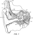
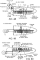
- FIG. 1 schematically shows the anatomy of a normal human ear.
- the ear typically transmits sounds, such as speech sounds, through the outer ear 101 to the tympanic membrane (eardrum) 102, which moves the bones of the middle ear 103 (malleus, incus, and stapes) that vibrate the oval window and round window openings of the cochlea 104.
- the cochlea 104 is a long narrow duct wound spirally about its axis for approximately two and a half turns.
- the cochlea 104 includes three chambers along its length, an upper chamber known as the scala vestibuli, a middle chamber known as the scala media, and a lower chamber known as the scala tympani.
- the cochlea 104 forms an upright spiraling cone with a center called the modiolus where the axons of the auditory nerve 113 reside.
- the fluid-filled cochlea 104 functions as a transducer to convert mechanical motion and energy and, in response, to generate electric pulses which are transmitted to the auditory nerve 113, and ultimately to the brain.
- the cochlear implant typically includes an electrode carrier having an electrode lead 109 and an electrode array 110, which is threaded into the cochlea 104.
- the electrode array is located in the auditory brainstem, midbrain or cortex, respectively. These electrodes may also be used for sensing neural tissue response signals, i.e., function as measurement electrodes.
- FIG. 1 shows some components of a typical cochlear implant system
- an external microphone provides an audio signal input to an external signal processor 111 which implements one of various known signal processing schemes.
- the processed signal is converted by the external signal processor 111 into a digital data format, such as a sequence of data frames, for transmission by an external coil 107 into a receiving stimulator processor 108.
- the receiving stimulator processor 108 may perform additional signal processing, such as error correction, pulse formation, etc., and produces a stimulation pattern (based on the extracted audio information) that is sent through the electrode lead 109 to the implanted electrode array 110.
- the electrode array 110 includes multiple stimulation contacts 112 on its surface that provide selective electrical stimulation of the cochlea 104.
- an audio prosthesis such as a cochlear implant
- some patient-specific operating parameters need to be determined in a fit adjustment procedure where the type and number of operating parameters are device dependent and stimulation strategy dependent.
- the fitting is based on subjective responses from the patient, where the behavioural thresholds (T-level) and maximum comfort levels (C-levels) are determined. If the user is uncooperative or has extremely limited expressive language skills (e.g., very young children), the subjective responses are not sufficient for fitting. Objective physiological measures can assist in such cases.
- the electrically evoked stapedial reflex (ESR), the electrically evoked auditory brainstem response (EABR), and the electrically evoked compound action potential (eCAP) are objective measures that may be used to assess the auditory nerve response to electrical stimulation.
- NAPs Neural Action Potentials
- eCAP electrically-evoked Compound Action Potential
- Gantz et al. Intraoperative Measures of Electrically Evoked Auditory Nerve Compound Action Potentials, American Journal of Otology 15 (2): 137-144 (1994 ).
- the eCAP is a measure of electrically elicited synchronous VIII nerve (auditory nerve) activity, and eCAP measures are performed by stimulation with a single pulse, where the signal is recorded over time after stimulus.
- the recording electrode is usually placed at the scala tympani of the inner ear.
- the overall response of the auditory nerve to an electrical stimulus is measured typically very close to the position of the nerve excitation. This neural response is caused by the super-position of single neural responses at the outside of the auditory nerve membranes.
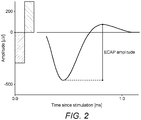
- FIG. 2 shows an example of measuring eCAP amplitude based solely on time since stimulation for a single response signal recording.
- the response signal is characterized by the amplitude between the minimum voltage (this peak is called typically N1) and the maximum voltage (peak is called typically P2), the so-called local extrema. These extrema among others represent the most prominent physiological landmarks of the ECAP signal.
- the amplitude of the eCAP at the measurement position is in most cases between approximately 10 ⁇ V and 1800 ⁇ V.
- eCAP recording paradigm is the "amplitude growth function," as described by Brown et al., Electrically Evoked Whole Nerve Action Potentials In Ineraid Cochlear Implant Users: Responses To Different Stimulating Electrode Configurations And Comparison To Psychophysical Responses, Journal of Speech and Hearing Research, vol. 39:453-467 (June 1996 ).
- This function is the relation between the amplitude of the stimulation pulse and the peak-to-peak voltage of the eCAP.
- the eCAP threshold is determined based on amplitude-growth functions or via expert systems using the correlation of the measured eCAP signal towards templates of typical noise and clear responses (see, e.g., U.S. Patent No. 7,818,052 and U.S. Patent Appl. No. 2005/021207 ).
- eCAP based measures are affected by efferent and afferent nerve fibers, where only afferent fibers contribute to the auditory percept.
- the necessary minimal strength of the corresponding stimulus might be up to about 11 charge units ( ⁇ nano coulomb) at a rate -40 Hz (see, e.g., MAESTRO Software 4.1, ART-task, at 10ms Measurement Gap). In a post-operative scenario, this might result for some individuals in a too loud perception.
- One common method for fit adjustment in a cochlear implant is to behaviorally find the auditory threshold (THR) and maximum comfortable loudness (MCL) value for each separate electrode contact.
- THR auditory threshold
- MCL maximum comfortable loudness
- the stimulation charge on a selected electrode channel is usually increased in steps from zero until the THR or MCL level is reached in a subjective procedure (e.g., method of adjustments) or an objective procedure (e.g., eCAP or ESR).
- This increase can be either stimulation burst duration or stimulation burst amplitude or a combination thereof.
- constant amplitude stimulation bursts with about 10-1000 msec duration are usually utilized.
- each electrode channel is fitted separately without using the information from already fitted electrode channels.
- Behavioural thresholds and maximum comfort levels are determined using pulse trains. If the frequency or the current (for single pulses within the pulse train) is increased, the stimulation of the auditory nerve by the pulse train is louder for the cochlear implant user.
- the individual loudness (reported by the cochlear implant user) plotted against increasing frequency or current is called the behavioural loudness growth function (LGF).
- LGF behavioural loudness growth function
- Some patient-specific operating parameters for a cochlear implant include:
- Another common method for fit adjustment in a cochlear implant is to "frequency match" the implant in one ear with the other, contralateral ear in order to enable the auditory system to detect correctly Interaural Level Differences (ILD) and Interaural Time Differences (ITD) since the signal process of both ears is connected.
- ILD Interaural Level Differences
- ITD Interaural Time Differences
- Localization of sound is influenced by ILD and ITD cues, but in general pitch cues are regarded as the most important factors affecting the performance of cochlear implant users.
- the bilateral matching of pitch is done by matching pitch to electrodes solely based on subjective measures.
- WO 2015/000528 A1 comprises a system comprising a device for neural stimulation of a cochlea of a patient's ipsilateral ear, a device for acoustic stimulation of the contralateral ear, and a fitting device for adjusting at least the neural stimulation device according to a perceptual behavioral response of the patient to combined neural stimulation of the cochlea at the ipsilateral ear and acoustic stimulation of the contralateral ear.
- the neural stimulation device comprises means for providing an input audio signal; a sound processor for generating a neural stimulation signal from the input audio signal; and a cochlear implant stimulation arrangement comprising a plurality of stimulation channels for stimulating the cochlea at various stimulation sites according to a neural stimulation signal, with each stimulation channel being attributed to a certain one of the stimulation sites.
- the acoustic stimulation device comprises a loudspeaker to be worn at the contralateral ear or in at least in part the ear canal of the contralateral ear for acoustically stimulating the contralateral ear according to an input audio signal.
- the fitting device comprises a signal generator cooperating with the neural stimulation device and with the acoustic stimulation device in order to generate, in a synchronized manner, a probe neural stimulation signal to be supplied to the cochlear implant stimulation arrangement for causing stimulation of the cochlea within a region around a selected one of the stimulation sites and a notch acoustic broadband masking signal to be supplied to the loudspeaker, with the notch acoustic broadband masking signal including a notch frequency region having a noise level below a masking level at which masking of the probe neural stimulation signal begins and with the noise level outside the notch frequency region being above the masking level.
- the system further comprises a unit for recording the perceptual behavioral response of the patient to the synchronized neural stimulation of the cochlea with the probe neural stimulation signal and the notch acoustic broadband masking signal, and a unit for programming the neural stimulation device according to the recorded perceptual response.
- a method of fitting a cochlear implant in a subject in order to frequency match the cochlear implant includes applying a tonal stimulus to a contralateral ear in order to mask efferent nerve fibers, measuring evoked compound action potential (CAP) signals in an ipsilateral ear during a refractory period, and measuring CAP signals in the ipsilateral ear outside of the refractory period.
- CAP evoked compound action potential
- the method further includes comparing the measured CAP signals during the refractory period to the measured CAP signals outside of the refractory period in order to determine a stimulation location on the cochlear implant that corresponds to a location in the ipsilateral ear that responds to a frequency of the tonal stimulus applied to the contralateral ear, and adjusting processing parameters of the cochlear implant based on the stimulation location.
- a system for fitting a cochlear implant in a subject in order to frequency match the cochlear implant includes a tissue stimulation device configured to generate a tonal stimulus to mask efferent nerve fibers in the subject and one or more response measurement contacts configured to measure evoked compound action potential (CAP) signals during a refractory period and outside of the refractory period.
- CAP evoked compound action potential
- the system further includes a frequency matching module in communication with the one or more response measurement contacts and configured to receive the CAP signals during the refractory period and outside of the refractory period and to determine a stimulation location on the cochlear implant based on a comparison of the received CAP signals during the refractory period and the received CAP signals outside of the refractory period and a parameter adjusting module in communication with the frequency matching module and configured to interface with the cochlear implant and to adjust processing parameters of the cochlear implant based on the stimulation location.
- a frequency matching module in communication with the one or more response measurement contacts and configured to receive the CAP signals during the refractory period and outside of the refractory period and to determine a stimulation location on the cochlear implant based on a comparison of the received CAP signals during the refractory period and the received CAP signals outside of the refractory period
- a parameter adjusting module in communication with the frequency matching module and configured to interface with the cochlear implant and to adjust processing parameters of
- the tonal stimulus may be applied by an acoustical, mechanical or electrical stimulation.
- the electrical stimulation may be applied with a second cochlear implant in the contralateral ear.
- the method may further include applying stimulation to the ipsilateral ear before measuring the CAP signals during the refractory period or outside of the refractory period.
- the method may further include applying a second tonal stimulus to the contralateral ear before measuring the CAP signals during the refractory period.
- the stimulation location on the cochlear implant may be between two stimulation contacts.
- the method may further include applying the tonal stimulus to the ipsilateral ear in order to mask efferent nerve fibers, measuring the CAP signals in the contralateral ear during a refractory period and outside of a refractory period, and comparing the measured CAP signals in the contralateral ear during the refractory period to the measured CAP signals in the contralateral ear outside of the refractory period in order to verify the processing parameters are correctly adjusted.
- the tissue stimulation device may be an acoustical device configured to deliver an acoustical stimulus to an outer or middle ear.
- the tissue stimulation device may be a mechanical device configured to deliver a mechanical stimulus to an outer ear or skull.
- the mechanical device may include a bone conduction transducer.
- the tissue stimulation device may be a stimulation electrode configured to deliver an electrical stimulus to neural tissue of an inner ear.
- the system may further include a second cochlear implant that includes the stimulation electrode configured to deliver the electrical stimulus to the neural tissue of the inner ear.
- the tissue stimulation device may be configured to generate two or more tonal stimuli to mask the efferent nerve fibers in the subject.
- the cochlear implant may include the one or more response measurement contacts configured to measure the CAP signals.
- the system may further include a tissue stimulation module in communication with the tissue stimulation device and configured to generate one or more tonal stimulation signals that are sent to the tissue stimulation device.
- the second cochlear implant may include one or more response measurement contacts in communication with the frequency matching module and configured to measure CAP signals, the cochlear implant may be configured to generate a tonal stimulus to mask efferent nerve fibers in the subject, and the frequency matching module may be configured to receive the CAP signals from the cochlear implant and the second cochlear implant in order to verify that the processing parameters are appropriately adjusted in the cochlear implant.
- Embodiments of the present invention are directed to systems and methods of fitting a cochlear implant in a subject in order to frequency-match the cochlear implant with the other ear.
- Embodiments make use of the intra-aural pathways of the auditory system (such as shown in FIG. 3 ) in order to measure patient-specific operating parameters objectively, such as frequency matching, in a cochlear implant.
- a considerable part of efferent fibers within the auditory nerve can be masked by contralateral stimulation (acoustical or electrical) due to the connection of both cochleae via afferent and efferent neurons to the olivocochlear bundle.
- Embodiments of the present invention compare neural answers to ipsilateral cochlear responses with contralateral stimuli to neural answers to ipsilateral responses without contralateral stimuli.
- a stimulus at a certain frequency, e.g., Fl at a contralateral site masks efferent fibers of that frequency at the ipsilateral, tested site and thus reduces the eCAP signal and changes the measured voltage at the corresponding frequency, e.g., Fl, at the tested site that includes the cochlear implant.
- Embodiments determine the location on the cochlear implant that corresponds to the location of maximum reduced response in the ipsilateral ear and correlates that implant location to the ear location in order to frequency-match the ipsilateral, tested ear with the cochlear implant to the other, contralateral ear.
- the frequency matching may then be verified by switching the tested site and the contralateral site and repeating the stimulation and measuring process. Details of illustrative embodiments are discussed below.
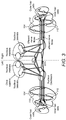
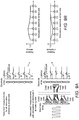
- FIG. 3 shows the auditory anatomy with the afferent and efferent nerve fibers (shown with hashed lines slanted in two different directions) along with the Nucleus Cochlearis, the Oliva Superior (including Nucleus medialis and Nucleus lateralis) and the cochlea 104.
- the efferent nerve fibers are depicted with the signal from the Oliva superior to the hair cells.
- the strength of signals sent from the oliva superior to the contralateral ear is quantified to be roughly about 2/3 of all efferent fibers associated with outer hair cells originating in the medial olivocochlear (MOC) and 20% of those originating in the lateral olivocochlear (LOC) neurons.
- MOC medial olivocochlear
- LOC lateral olivocochlear
- the number of neurons associated with the outer hair cells is believed to be about 10% of the total number of neurons for healthy cochleae.
- the relative number of the nerve fibers associated with outer hair cells increases since mainly the neurons associated with inner hair cells degenerate. In the case of severe sensorineural deafness, it is believed that the fibers associated with outer hair cells persist in greater numbers than the ones associated with inner hair cells, since these nerve fibers seem to be more resistant to retrograde degeneration.
- the attenuation of the CAP amplitude is expected to be in the range 3-20% (about 30% for severe neural deafness) for humans affected by hearing loss.
- the strength of attenuation varies for each individual, and subjects with low CAP suppression show a lower discharge rate (depending on refractory times) of efferent nerve fibers.
- CAP suppression varies with frequency. The most effective frequency is dependent on the frequency of ipsilateral stimuli. In general, the higher the frequency of ipsilateral stimuli, the less effective the contralateral masking with frequency matched tones is expected.
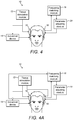
- FIG. 4 shows a frequency matching system 10 for fitting a cochlear implant and FIG. 5 shows a method of frequency matching 100 a cochlear implant according to embodiments of the present invention.
- FIG. 4A shows a frequency matching system 10 configuration that includes a verification process.
- embodiments of the system and method are used with a contralateral ear or "masker side” that is sensitive to acoustical stimuli or supported with a cochlear implant and with an ipsilateral ear or "test side” that is supported with a cochlear implant to be fitted.
- the system applies a tonal stimulus, which is a frequency specific pure tone or single frequency, or a set of pure tones or frequencies.
- the frequency matching system 10 includes a tissue stimulation module 12 that generates one or more tonal stimulation signals that are sent to a tissue stimulation device, such as an acoustical device 14 or a cochlear implant 16.
- the tissue stimulation device 14, 16 then generates an acoustical stimulus or an electrical stimulus of one or more tones or frequencies and applies the tonal stimulus to a contralateral ear or masker side (step 120) in order to mask efferent nerve fibers.
- masked nerve fibers are those fibers that have been stimulated, in this case at a certain frequency, and are unable to provide an additional evoked response until a refractory period has ended.
- masked nerve fibers provide no additional neural response during their refractory period. Consequently, any CAP measure during this refractory period for the ear to be frequency matched will not measure the signal contribution from the masked efferent nerve fibers, and the CAP measured is therefore reduced by this amount.
- the CAP signals are measured in an ipsilateral ear during a refractory period (step 130) and the CAP signals are measured in the ipsilateral ear outside of the refractory period (step 140).
- One or more response measurement contacts such as stimulation contacts 112 on a stimulation electrode array 110 in the cochlear implant 16 to be fitted, are configured to measure the CAP signals during and outside of the refractory period.
- various testing configurations may be used to measure the CAP signals. For example, two main types of test scenarios may be used: passive testing, where only CAPs are recorded without ipsilateral stimulation, such as shown in FIG.
- Test stimuli may include stimulation with a single pulse or a sequence of pulses at a single electrode and recording at a second, or stimulation with multiple electrodes or stimuli and recording on multiple electrodes.
- the CAP signal recorded at the test side due to an ipsilateral stimulus only (without contralateral stimulation) is referred to as a "base-line” signal and an CAP recording where a contralateral stimulation takes place is referred to as an "attenuated" signal.
- tones at certain frequencies are used.
- the stimuli may be applied acoustically, mechanically or electrically on multiple electrodes, as shown in FIGS. 6 and 7 .
- tone bursts at one or more selected frequencies may be applied using a standard loudspeaker with headphones or a microphone.
- Distortion Product Otoacoustic Emissions can be used to measure ipsilateral efferent signals and to verify ipsilateral activation of outer hair cells due to intact processing of the acoustical stimulus via the middle ear and the cochlea.
- efferent processes affect the ipsilateral side as well, the magnitude of efferent processes can be measured for ipsilateral processes and can be estimated using DP-OAE for contralateral processes. If the cochlea where the masker stimuli are applied is supplied with a cochlear implant, tone bursts at one or more selected frequencies may be applied using that cochlear implant, and ipsilateral efferent signals may be estimated on behalf of CAP recordings following sequences of pulses, e.g., with rates >100 pulses/second.
- contralateral maskers may be used, as known by those skilled in the art, such as maskers of short duration (e.g., about 400ms) and long durations (e.g., about 2-10s). If short duration maskers are used (e.g., ⁇ 1s), the masker-signal on the contralateral ear is stopped before each test stimulus and CAP recording on the ipsilateral ear. After a period of time, the masker signal on the contralateral ear is restarted once the peripheral influence disappears (estimated to be about ⁇ 0.5s), and is stopped again for the next test stimuli on the ipsilateral ear.
- short duration maskers e.g., ⁇ 1s
- the masker-signal on the contralateral ear is stopped before each test stimulus and CAP recording on the ipsilateral ear. After a period of time, the masker signal on the contralateral ear is restarted once the peripheral influence disappears (estimated to be about ⁇ 0.5s), and is stopped again for the next test stimul
- the test stimuli and recordings can be performed during the 2-13 seconds and after the masker onset on the contralateral side.
- sequences of pulses exceeding a certain duration e.g., few milliseconds
- a rate e.g., >15 pulses/s
- the strength of masker stimuli can be varied for both setups.
- a strong masker e.g., high amplitude, such as at MCL level
- the ipsilateral applied test-stimuli may be preferably at moderate strength (e.g., about 50% of MCL) to show highest impact of attenuation.
- FIGS. 8A-8C show schematic views of a portion of a cochlea during a frequency matching process for different testing scenarios.
- FIG. 8A shows a test setup for an acoustical stimulation device 14, and the activation of outer hair cells with two different frequencies (frequencies f1 and f2, cubic distortion product 2*f1-f2).
- FIG. 8A shows a simplified view of the DP-OAE measurement of applying an acoustical masker. Besides the hair cells of the corresponding frequency regions for the applied stimuli (f1 and f2, f2>f1), outer hair cells corresponding to frequencies 2*f1-f2 (and f2-f1) are also elicited.
- FIG. 8B shows a simplified view of an electrical masker.
- Electrodes For both masking conditions, nerve fibers (connected to inner and outer hair cells) are elicited.
- FIG. 8C the test conditions are sketched. For passive testing, no stimulation is applied on this ear. The eCAP corresponding to the elicited efferent nerve fibers is measured (for one, more or each electrode contact).
- a stimulus is applied (shown here for a single electrode contact, but applied sequentially on all electrode contacts) and the eCAP is measured on a second electrode contact.
- a "base-line” measurement without contralateral masking is compared to the "attenuated” measurement with contralateral stimulation. The largest effect on the eCAP signal is expected at the electrode contact which is closest to the masked fibers.
- a frequency matching module 18 compares the measured eCAP signals during the refractory period to the measured eCAP signals outside of the refractory period in order to determine a stimulation location on the cochlear implant (step 150) that corresponds to a location in the ipsilateral ear that responds to a frequency of the tonal stimulus applied to the contralateral ear. Since contralateral efferent pathways are tonotopically organized, the masking effect of the contralateral stimulus at a certain frequency (for comparison with DP-OAE: f2) is maximal at the frequency-matched region of the ipsilateral cochlea.
- the magnitude of the masking effect can be determined by the difference in eCAP amplitude/latency of the "base-line” and “attenuated” eCAP, or the difference of the "base-line” and “attenuated” eCAP threshold with slope or the difference of the "base-line” and “attenuated” eCAP recovery. Therefore, the stimulation location on the cochlear implant that measures the biggest change or impact due to the contralateral masker is defined as "frequency-matched" to the applied masking signal.
- a parameter adjusting module 20 adjusts processing parameters of the cochlear implant 16 to be fitted on the test side based on the stimulation location (step 160).
- the roles of masker and test side may be interchanged, and the frequency matching may be verified, such a configuration of the system 10 is shown in FIG. 4A .
- no difference in setup is needed except the roles of the two cochlear implants are interchanged.
- DP-OAE may be used.
- the process in steps 120 through 160 may be repeated for any number of frequencies until the cochlear implant 16 to be fitted is frequency mapped to the desired frequencies in the ipsilateral ear.
- Cochlea "A” is supplied with a cochlear implant to be fitted.
- the process may follow the steps below:
- a predefined measurement setup is performed on all electrode contacts of cochlear implant in cochlea "A" in step 1, e.g., Amplitude Growth Functions and Recovery Functions using for example and without limitation:
- a noise restricted to the chosen frequency or frequencies is applied on cochlea "B” with acoustical stimuli or electrical stimuli on the selected electrode contact(s) in step 2.
- the measurement setup, as in step 1, is applied on all electrode contacts of the cochlear implant in cochlea "A".
- the "base-line” signal is compared with the "attenuated” signal.
- the one or more electrode contacts of the cochlear implant in cochlea "A” showing the biggest impact (e.g., as shown and described in more detail below in FIGS. 9A-10B ) due to the contralateral masker is defined as "frequency-matched" to the applied masking signal (noise restricted to a particular frequency or a particular stimulation electrode contact) in cochlea "B".
- the predefined measurement setup includes a single stimulation pulse (applied at a single electrode contact and recorded at another electrode contact at the test side) for each electrode contact on the array. Therefore, the "base-line” signals at the test side ("A") are single eCAP recordings.
- the "attenuated” signals are derived using a pulse train at a certain electrode contact of the masking side ("B") as masker noise and a simultaneous, single stimulation pulse at the test side (as used for the "base-line” signals) are applied. Again, as for “base-line” signals, “attenuated” signals are represented by single eCAP recordings.
- the latency of the minimum and the amplitude between the minimum and the maximum are regarded as characteristic parameters.
- the relative magnitude of the "attenuated" signal compared to the "base-line” signal is shown in FIG. 9B , where the change in latency as well as in amplitude (determined based on the minima and maxima of the eCAP) of the recorded ECAP is shown.
- all parameters concerning the morphology and intensity are suitable.
- sequences of recordings e.g., Amplitude Growth Functions (AGF), Recovery Functions (RF), or Spread of Excitation Functions (SoE)
- AGF Amplitude Growth Functions
- RF Recovery Functions
- SoE Spread of Excitation Functions
- the derived relative parameters may be plotted for each masking channel separately against the stimulation channel at the test side.
- the derived functions may be interpolated using exponential functions in order to determine a continuous pattern of attenuated, relative parameters.
- the frequency matched stimulation side of a channel at the masking side might be between two electrode contacts at the test-side.
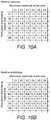
- the position with the most impact may be interpolated by any known interpolation method, and the model may be, for example, one of electrical field distribution within the cochlear. This case is not shown and only the magnitude of attenuation at particular stimulation electrode contacts of the test side are regarded for the parameter matrices shown in FIGS. 10A and 10B .
- FIG. 10A shows a matrix for relative latencies
- FIG. 10B shows a matrix for relative amplitudes that may be derived.
- the single lines are summarizing the effects of a masking signal of single electrode contacts at the masking side
- the columns are the relative magnitudes of parameters of single electrode contacts at the test side.
- the lines and columns of the derived matrices might reflect certain frequencies, e.g., if the stimuli used at the masker and test side are eliciting certain frequencies only.
- single electrode contacts represent single frequencies.
- the frequency-matched channel i.e., the channel showing the biggest impact of the masker
- the frequency-matched channel is identified by selecting the corresponding line (reflecting channel at masker side) of the amplitude and latency matrices and determining the column with the smallest to largest entry (reflecting the channel at test side).
- the selection of the corresponding line for masking channel 3 and the determined frequency matched channel 3 at the test side is highlighted with bold numbers in FIGS. 10A and 10B and shown graphically in FIG. 9B .
- the frequency matched channel at the masking side can be selected.
- the line with the smallest to largest entry is selected (channel at masking side).
- the selection of the corresponding column for test channel 3 and the determined frequency matched channel 3 at the masker side is highlighted with italic numbers in FIGS. 10A and 10B and shown graphically in FIG. 9B .
- the metric used for selecting the smallest to largest entry of each matrix can be extended to two dimensions in order to take both alternatives (selection via lines and columns) simultaneously into account.
- multidimensional matrices e.g., including amplitudes and latencies, deduced parameters from AGFs, RFs, or SoEs, etc.
- suitable multidimensional metrics e.g., different weights for amplitudes and latencies
- white noise or pulse bursts may be applied on the contralateral side.
- the efferent fibers are masked with the contralateral stimulus within the whole VIII nerve, which reduces the proportion of efferent fibers within the measured eCAP signal on the ipsilateral, test side. Therefore, the measured response is representing the auditory percept at a higher order. According to the representation of the auditory percept via eCAP signal considering both afferent and efferent nerve fibers and. the strength of the afferent and efferent contribution, estimations based on eCAP recordings of THR and MCL may be strengthened.
- a broad-band white noise may be used in order to mask a maximum number of efferent fibers responding to contralateral stimuli.
- a “base-line” signal as well as an “attenuated” signal is measured. If a single pulse (or short pulse sequence at a low rate without any activation of ipsilateral efferent processes) is used as test stimulus, the difference in eCAP amplitude of "base-line” and "attenuated” signal is expected to be at -30%.
- AGF Amplitude Growth Functions
- RF Recovery Functions
- the correlation of the determined eCAP threshold of the "base-line” AGFs with the psychophysical measures (MCL, THR) is limited in clinical practice. Since for “attenuated” AGFs, the relative number of afferent fibers contributing to the eCAP signal is higher, the correlation of "attenuated” eCAP threshold (the ratio of "base-line” and “attenuated” eCAP threshold) and MCL is increased. If a selected electrode is already frequency matched to contralateral stimuli, such as described above, the broad-band noise at the masker side can be separated for the particular matched frequency. The resulting "base-line” and “attenuated” eCAPs for stimuli at the selected electrode contact should show only minor differences. Since the loudness percept is different, the range of stimulation intensities for the test stimuli is increased. Thus, if an eCAP signal is weak, this procedure may help to get a more clear recording.
- the effect of masked efferent nerve fibers is usually measured indirectly by regarding the attenuation of DP-OAE amplitude (with CAP recordings) due to the presence of contralateral stimulation.
- MOC medial olivocochlear
- the noise should be applied at the maximal level where still no middle ear muscle reflex is visible. If the subject is sedated, the stimuli can be louder since middle ear muscle movements are suppressed. If the contralateral noise is applied only for a short period ( ⁇ 400ms before ipsilateral stimulus), the sound pressure of the noise affects the attenuation at a higher magnitude than for a longer duration of the applied noise and might be chosen at a lower level. During the 2-10ms period after onset of contralateral noise, tone pulses on the ipsilateral side are applied. Attenuation effects are expected to be largest for moderate loud ipsilateral stimuli and present for all frequencies, but largest for the characteristic frequency.
- the attenuation is usually quantified as the necessary increase of sound pressure of the ipsilateral stimuls in order to elicit the same CAP with contralateral masking stimuli as was measured without contralateral stimuli.
- An alternative measure is the attenuation for absolute CAP amplitudes, which shows a decrease of typically about 20-25% for short term contralateral noise (duration ⁇ 400ms) and even higher using longer durations of contralateral noise (>2s) depending on the sound pressure level of the ipsilateral stimuli (higher attenuation for low sound pressure).
- embodiments of the system may be implemented as hardware, software (e.g., a computer program product), or a combination of both software and hardware.
- embodiments may be implemented as a computer program product for use with a computer system.
- Such implementation may include a series of computer instructions fixed either on a tangible medium, such as a computer readable medium (e.g., a diskette, CD-ROM, ROM, or fixed disk) or transmittable to a computer system, via a modem or other interface device, such as a communications adapter connected to a network over a medium.
- the medium may be either a tangible medium (e.g., optical or analog communications lines) or a medium implemented with wireless techniques (e.g., microwave, infrared or other transmission techniques).
- the series of computer instructions may embody all or part of the functionality previously described herein with respect to the system.
- Those skilled in the art should appreciate that such computer instructions may be written in a number of programming languages for use with many computer architectures or operating systems.
- such instructions may be stored in any memory device, such as semiconductor, magnetic, optical or other memory devices, and may be transmitted using any communications technology, such as optical, infrared, microwave, or other transmission technologies.
- It is expected that such a computer program product may be distributed as a removable medium with accompanying printed or electronic documentation (e.g., shrink wrapped software), preloaded with a computer system (e.g., on system ROM or fixed disk), or distributed from a server or electronic bulletin board over the network (e.g., the Internet or World Wide Web).
Description
- The present invention relates to implant fitting by sensing neural tissue responding to electrical stimulation signals, especially for hearing implant systems such as cochlear implant systems.
-
FIG. 1 schematically shows the anatomy of a normal human ear. The ear typically transmits sounds, such as speech sounds, through theouter ear 101 to the tympanic membrane (eardrum) 102, which moves the bones of the middle ear 103 (malleus, incus, and stapes) that vibrate the oval window and round window openings of thecochlea 104. Thecochlea 104 is a long narrow duct wound spirally about its axis for approximately two and a half turns. Thecochlea 104 includes three chambers along its length, an upper chamber known as the scala vestibuli, a middle chamber known as the scala media, and a lower chamber known as the scala tympani. Thecochlea 104 forms an upright spiraling cone with a center called the modiolus where the axons of theauditory nerve 113 reside. In response to received sounds transmitted by themiddle ear 103, the fluid-filledcochlea 104 functions as a transducer to convert mechanical motion and energy and, in response, to generate electric pulses which are transmitted to theauditory nerve 113, and ultimately to the brain. - Hearing is impaired when there are problems in the transducer function within the inner ear to transduce external sounds into meaningful action potentials along the neural substrate of the
cochlea 104. To improve impaired hearing, there are several types of auditory prostheses that have been developed, such as cochlear implants, brainstem-implants, midbrain-implants or cortical implants, that electrically stimulate auditory nerve tissue with small currents delivered by multiple electrode contacts distributed along an implant electrode. The cochlear implant typically includes an electrode carrier having anelectrode lead 109 and anelectrode array 110, which is threaded into thecochlea 104. For brain-stem, midbrain and cortical implants, the electrode array is located in the auditory brainstem, midbrain or cortex, respectively. These electrodes may also be used for sensing neural tissue response signals, i.e., function as measurement electrodes. -
FIG. 1 shows some components of a typical cochlear implant system where an external microphone provides an audio signal input to anexternal signal processor 111 which implements one of various known signal processing schemes. The processed signal is converted by theexternal signal processor 111 into a digital data format, such as a sequence of data frames, for transmission by anexternal coil 107 into areceiving stimulator processor 108. Besides extracting the audio information, the receivingstimulator processor 108 may perform additional signal processing, such as error correction, pulse formation, etc., and produces a stimulation pattern (based on the extracted audio information) that is sent through theelectrode lead 109 to the implantedelectrode array 110. Typically, theelectrode array 110 includesmultiple stimulation contacts 112 on its surface that provide selective electrical stimulation of thecochlea 104. - For an audio prosthesis, such as a cochlear implant, to work correctly, some patient-specific operating parameters need to be determined in a fit adjustment procedure where the type and number of operating parameters are device dependent and stimulation strategy dependent. In some cases, the fitting is based on subjective responses from the patient, where the behavioural thresholds (T-level) and maximum comfort levels (C-levels) are determined. If the user is uncooperative or has extremely limited expressive language skills (e.g., very young children), the subjective responses are not sufficient for fitting. Objective physiological measures can assist in such cases. For example, the electrically evoked stapedial reflex (ESR), the electrically evoked auditory brainstem response (EABR), and the electrically evoked compound action potential (eCAP) are objective measures that may be used to assess the auditory nerve response to electrical stimulation.
- To collect information about the electrode - nerve interface, a commonly used objective measurement is based on the measurement of Neural Action Potentials (NAPs) such as the electrically-evoked Compound Action Potential (eCAP), as described by Gantz et al., Intraoperative Measures of Electrically Evoked Auditory Nerve Compound Action Potentials, American Journal of Otology 15 (2): 137-144 (1994). The eCAP is a measure of electrically elicited synchronous VIII nerve (auditory nerve) activity, and eCAP measures are performed by stimulation with a single pulse, where the signal is recorded over time after stimulus. In this approach, the recording electrode is usually placed at the scala tympani of the inner ear. The overall response of the auditory nerve to an electrical stimulus is measured typically very close to the position of the nerve excitation. This neural response is caused by the super-position of single neural responses at the outside of the auditory nerve membranes.
- These recordings show characteristic minima (N1, N2) and maxima (PI, P2, P3), where the difference in amplitude between P2-N1 (eCAP-amplitude) of the recorded signal is of special interest.
FIG. 2 shows an example of measuring eCAP amplitude based solely on time since stimulation for a single response signal recording. The response signal is characterized by the amplitude between the minimum voltage (this peak is called typically N1) and the maximum voltage (peak is called typically P2), the so-called local extrema. These extrema among others represent the most prominent physiological landmarks of the ECAP signal. The amplitude of the eCAP at the measurement position is in most cases between approximately 10 µV and 1800 µV. One eCAP recording paradigm is the "amplitude growth function," as described by Brown et al., Electrically Evoked Whole Nerve Action Potentials In Ineraid Cochlear Implant Users: Responses To Different Stimulating Electrode Configurations And Comparison To Psychophysical Responses, Journal of Speech and Hearing Research, vol. 39:453-467 (June 1996). This function is the relation between the amplitude of the stimulation pulse and the peak-to-peak voltage of the eCAP. - The eCAP threshold is determined based on amplitude-growth functions or via expert systems using the correlation of the measured eCAP signal towards templates of typical noise and clear responses (see, e.g.,
U.S. Patent No. 7,818,052 andU.S. Patent Appl. No. 2005/021207 ). Amplitude growth functions (AGF) are a sequence of measurements with increasing stimulation intensity, and since the eCAP-amplitude increases, the input (stimulation intensity) / output (eCAP amplitude) function (usually estimated by a linear function: out= in * eCAP slope + eCAP offset) can be used to extrapolate the maximal stimulation intensity where no eCAP signal is present, the eCAP threshold. Expert systems increase the stimulation intensity successively until a signal is present, and the minimal stimulation intensity necessary yields the eCAP threshold. eCAP based measures are affected by efferent and afferent nerve fibers, where only afferent fibers contribute to the auditory percept. To elicit an eCAP which can be recorded, the necessary minimal strength of the corresponding stimulus might be up to about 11 charge units (∼nano coulomb) at a rate -40 Hz (see, e.g., MAESTRO Software 4.1, ART-task, at 10ms Measurement Gap). In a post-operative scenario, this might result for some individuals in a too loud perception. - One common method for fit adjustment in a cochlear implant is to behaviorally find the auditory threshold (THR) and maximum comfortable loudness (MCL) value for each separate electrode contact. For this, the stimulation charge on a selected electrode channel is usually increased in steps from zero until the THR or MCL level is reached in a subjective procedure (e.g., method of adjustments) or an objective procedure (e.g., eCAP or ESR). This increase can be either stimulation burst duration or stimulation burst amplitude or a combination thereof. For this procedure, constant amplitude stimulation bursts with about 10-1000 msec duration are usually utilized. See, e.g., Rätz, Fitting Guide for First Fitting with MAESTRO 2.0, MED-EL, Fürstenweg 77a, 6020 Innsbruck, 1.0 Edition, 2007. AW 5420 Rev. 1.0 (English_EU). Typically, each electrode channel is fitted separately without using the information from already fitted electrode channels.
- Behavioural thresholds and maximum comfort levels are determined using pulse trains. If the frequency or the current (for single pulses within the pulse train) is increased, the stimulation of the auditory nerve by the pulse train is louder for the cochlear implant user. The individual loudness (reported by the cochlear implant user) plotted against increasing frequency or current is called the behavioural loudness growth function (LGF). The linkage between subjective loudness perception and eCAP threshold is done using adjustment factors: linear dependency of THR with MCL using fixed values, eCAP threshold and eCAP slope.
- Some patient-specific operating parameters for a cochlear implant include:
- THR1 (lower detection threshold of stimulation amplitude) for Electrode Contact 1
- MCL1 (most comfortable loudness) for Electrode Contact 1
- Phase Duration for Electrode Contact 1
- Amplitude for Electrode Contact 1
- Pulse Rate for Electrode Contact 1
- THR2 for Electrode
Contact 2 - MCL2 for Electrode
Contact 2 - Phase Duration for
Electrode Contact 2 - Amplitude for
Electrode Contact 2 - -Pulse Rate for
Electrode Contact 2
... - Compression
- Parameters of frequency, e.g., electrode contact mapping
- Parameters describing the electrical field distribution, e.g., spatial spread
- Another common method for fit adjustment in a cochlear implant is to "frequency match" the implant in one ear with the other, contralateral ear in order to enable the auditory system to detect correctly Interaural Level Differences (ILD) and Interaural Time Differences (ITD) since the signal process of both ears is connected. Localization of sound is influenced by ILD and ITD cues, but in general pitch cues are regarded as the most important factors affecting the performance of cochlear implant users. Currently, the bilateral matching of pitch is done by matching pitch to electrodes solely based on subjective measures.
-
WO 2015/000528 A1 comprises a system comprising a device for neural stimulation of a cochlea of a patient's ipsilateral ear, a device for acoustic stimulation of the contralateral ear, and a fitting device for adjusting at least the neural stimulation device according to a perceptual behavioral response of the patient to combined neural stimulation of the cochlea at the ipsilateral ear and acoustic stimulation of the contralateral ear. The neural stimulation device comprises means for providing an input audio signal; a sound processor for generating a neural stimulation signal from the input audio signal; and a cochlear implant stimulation arrangement comprising a plurality of stimulation channels for stimulating the cochlea at various stimulation sites according to a neural stimulation signal, with each stimulation channel being attributed to a certain one of the stimulation sites. The acoustic stimulation device comprises a loudspeaker to be worn at the contralateral ear or in at least in part the ear canal of the contralateral ear for acoustically stimulating the contralateral ear according to an input audio signal. The fitting device comprises a signal generator cooperating with the neural stimulation device and with the acoustic stimulation device in order to generate, in a synchronized manner, a probe neural stimulation signal to be supplied to the cochlear implant stimulation arrangement for causing stimulation of the cochlea within a region around a selected one of the stimulation sites and a notch acoustic broadband masking signal to be supplied to the loudspeaker, with the notch acoustic broadband masking signal including a notch frequency region having a noise level below a masking level at which masking of the probe neural stimulation signal begins and with the noise level outside the notch frequency region being above the masking level. The system further comprises a unit for recording the perceptual behavioral response of the patient to the synchronized neural stimulation of the cochlea with the probe neural stimulation signal and the notch acoustic broadband masking signal, and a unit for programming the neural stimulation device according to the recorded perceptual response. - In accordance with one embodiment of the invention, a method of fitting a cochlear implant in a subject in order to frequency match the cochlear implant includes applying a tonal stimulus to a contralateral ear in order to mask efferent nerve fibers, measuring evoked compound action potential (CAP) signals in an ipsilateral ear during a refractory period, and measuring CAP signals in the ipsilateral ear outside of the refractory period. The method further includes comparing the measured CAP signals during the refractory period to the measured CAP signals outside of the refractory period in order to determine a stimulation location on the cochlear implant that corresponds to a location in the ipsilateral ear that responds to a frequency of the tonal stimulus applied to the contralateral ear, and adjusting processing parameters of the cochlear implant based on the stimulation location.
- In accordance with another embodiment of the invention, a system for fitting a cochlear implant in a subject in order to frequency match the cochlear implant includes a tissue stimulation device configured to generate a tonal stimulus to mask efferent nerve fibers in the subject and one or more response measurement contacts configured to measure evoked compound action potential (CAP) signals during a refractory period and outside of the refractory period. The system further includes a frequency matching module in communication with the one or more response measurement contacts and configured to receive the CAP signals during the refractory period and outside of the refractory period and to determine a stimulation location on the cochlear implant based on a comparison of the received CAP signals during the refractory period and the received CAP signals outside of the refractory period and a parameter adjusting module in communication with the frequency matching module and configured to interface with the cochlear implant and to adjust processing parameters of the cochlear implant based on the stimulation location.
- In some embodiments, the tonal stimulus may be applied by an acoustical, mechanical or electrical stimulation. The electrical stimulation may be applied with a second cochlear implant in the contralateral ear. The method may further include applying stimulation to the ipsilateral ear before measuring the CAP signals during the refractory period or outside of the refractory period. The method may further include applying a second tonal stimulus to the contralateral ear before measuring the CAP signals during the refractory period. The stimulation location on the cochlear implant may be between two stimulation contacts. The method may further include applying the tonal stimulus to the ipsilateral ear in order to mask efferent nerve fibers, measuring the CAP signals in the contralateral ear during a refractory period and outside of a refractory period, and comparing the measured CAP signals in the contralateral ear during the refractory period to the measured CAP signals in the contralateral ear outside of the refractory period in order to verify the processing parameters are correctly adjusted. The tissue stimulation device may be an acoustical device configured to deliver an acoustical stimulus to an outer or middle ear. The tissue stimulation device may be a mechanical device configured to deliver a mechanical stimulus to an outer ear or skull. The mechanical device may include a bone conduction transducer. The tissue stimulation device may be a stimulation electrode configured to deliver an electrical stimulus to neural tissue of an inner ear. The system may further include a second cochlear implant that includes the stimulation electrode configured to deliver the electrical stimulus to the neural tissue of the inner ear. The tissue stimulation device may be configured to generate two or more tonal stimuli to mask the efferent nerve fibers in the subject. The cochlear implant may include the one or more response measurement contacts configured to measure the CAP signals. The system may further include a tissue stimulation module in communication with the tissue stimulation device and configured to generate one or more tonal stimulation signals that are sent to the tissue stimulation device. When the tissue stimulation device is a second cochlear implant, the second cochlear implant may include one or more response measurement contacts in communication with the frequency matching module and configured to measure CAP signals, the cochlear implant may be configured to generate a tonal stimulus to mask efferent nerve fibers in the subject, and the frequency matching module may be configured to receive the CAP signals from the cochlear implant and the second cochlear implant in order to verify that the processing parameters are appropriately adjusted in the cochlear implant.
-
-
FIG. 1 shows anatomical structures of a human ear having a cochlear implant system; -
FIG. 2 shows an example of measuring eCAP amplitude based solely on time since stimulation for a single response signal recording; -
FIG. 3 shows a schematic view of the auditory anatomy showing the afferent and efferent nerve fibers along with the Nucleus Cochlearis, the Oliva Superior (especially Nucleus medialis and Nucleus lateralis) and the cochlear; -
FIG. 4 shows a frequency matching system for fitting a cochlear implant in a subject according to embodiments of the present invention; -
FIG. 4A shows another configuration for a frequency matching system for fitting a cochlear implant according to embodiments of the present invention; -
FIG. 5 shows a method of frequency matching a cochlear implant according to embodiments of the present invention; -
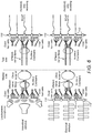
FIG. 6 shows a schematic view of a portion of a frequency matching system with an acoustical or electrical stimulus on a masker side and using a passive CAP testing procedure on a test side according to embodiments of the present invention; -
FIG. 7 shows a schematic view of a portion of a frequency matching system with an acoustical or electrical stimulus on a masker side and using an active CAP testing procedure on a test side according to embodiments of the present invention; -
FIGS. 8A-8C show schematic views of a portion of a cochlea during a frequency matching process according to embodiments of the present invention; -
FIG. 9A shows a schematic view of exemplary baseline and attenuated measurements, andFIG. 9B shows the change in amplitudes and latencies of CAP recordings for the attenuated measurement compared to the baseline measurement ofFIG. 9A according to embodiments of the present invention; and -
FIGS. 10A and 10B show exemplary relative values for amplitudes and latencies for measurements with masking stimuli on different electrodes at the masking side according to embodiments of the present invention. - Embodiments of the present invention are directed to systems and methods of fitting a cochlear implant in a subject in order to frequency-match the cochlear implant with the other ear. Embodiments make use of the intra-aural pathways of the auditory system (such as shown in
FIG. 3 ) in order to measure patient-specific operating parameters objectively, such as frequency matching, in a cochlear implant. A considerable part of efferent fibers within the auditory nerve can be masked by contralateral stimulation (acoustical or electrical) due to the connection of both cochleae via afferent and efferent neurons to the olivocochlear bundle. Embodiments of the present invention compare neural answers to ipsilateral cochlear responses with contralateral stimuli to neural answers to ipsilateral responses without contralateral stimuli. - The difference between both responses is considered to be due to the connection of the intra-aural pathways. Therefore, applying a stimulus at a certain frequency, e.g., Fl, at a contralateral site masks efferent fibers of that frequency at the ipsilateral, tested site and thus reduces the eCAP signal and changes the measured voltage at the corresponding frequency, e.g., Fl, at the tested site that includes the cochlear implant. Embodiments then determine the location on the cochlear implant that corresponds to the location of maximum reduced response in the ipsilateral ear and correlates that implant location to the ear location in order to frequency-match the ipsilateral, tested ear with the cochlear implant to the other, contralateral ear. The frequency matching may then be verified by switching the tested site and the contralateral site and repeating the stimulation and measuring process. Details of illustrative embodiments are discussed below.
-
FIG. 3 shows the auditory anatomy with the afferent and efferent nerve fibers (shown with hashed lines slanted in two different directions) along with the Nucleus Cochlearis, the Oliva Superior (including Nucleus medialis and Nucleus lateralis) and thecochlea 104. The efferent nerve fibers are depicted with the signal from the Oliva superior to the hair cells. The strength of signals sent from the oliva superior to the contralateral ear is quantified to be roughly about 2/3 of all efferent fibers associated with outer hair cells originating in the medial olivocochlear (MOC) and 20% of those originating in the lateral olivocochlear (LOC) neurons. It is believed that roughly 1/3 of all efferent fibers associated with outer hair cells are elicited most effectively by contralateral stimuli, and 2/3 by ipsilateral stimuli. The number of neurons associated with the outer hair cells is believed to be about 10% of the total number of neurons for healthy cochleae. For degenerated cochleae, the relative number of the nerve fibers associated with outer hair cells increases since mainly the neurons associated with inner hair cells degenerate. In the case of severe sensorineural deafness, it is believed that the fibers associated with outer hair cells persist in greater numbers than the ones associated with inner hair cells, since these nerve fibers seem to be more resistant to retrograde degeneration. Based on these studies, the attenuation of the CAP amplitude is expected to be in the range 3-20% (about 30% for severe neural deafness) for humans affected by hearing loss. The strength of attenuation varies for each individual, and subjects with low CAP suppression show a lower discharge rate (depending on refractory times) of efferent nerve fibers. If tones are used for the stimulus on the contralateral side, rather than noise, CAP suppression varies with frequency. The most effective frequency is dependent on the frequency of ipsilateral stimuli. In general, the higher the frequency of ipsilateral stimuli, the less effective the contralateral masking with frequency matched tones is expected. -
FIG. 4 shows afrequency matching system 10 for fitting a cochlear implant andFIG. 5 shows a method of frequency matching 100 a cochlear implant according to embodiments of the present invention.FIG. 4A shows afrequency matching system 10 configuration that includes a verification process. As described below, embodiments of the system and method are used with a contralateral ear or "masker side" that is sensitive to acoustical stimuli or supported with a cochlear implant and with an ipsilateral ear or "test side" that is supported with a cochlear implant to be fitted. In addition, the system applies a tonal stimulus, which is a frequency specific pure tone or single frequency, or a set of pure tones or frequencies. - The
frequency matching system 10 includes atissue stimulation module 12 that generates one or more tonal stimulation signals that are sent to a tissue stimulation device, such as anacoustical device 14 or acochlear implant 16. Thetissue stimulation device - After the tonal stimulus is applied to the contralateral ear, the CAP signals are measured in an ipsilateral ear during a refractory period (step 130) and the CAP signals are measured in the ipsilateral ear outside of the refractory period (step 140). One or more response measurement contacts, such as
stimulation contacts 112 on astimulation electrode array 110 in thecochlear implant 16 to be fitted, are configured to measure the CAP signals during and outside of the refractory period. As shown inFIGS. 6 and7 , various testing configurations may be used to measure the CAP signals. For example, two main types of test scenarios may be used: passive testing, where only CAPs are recorded without ipsilateral stimulation, such as shown inFIG. 6 , and active testing, where an ipsilateral stimulus is applied and a CAP is recorded, as shown inFIG. 7 . Test stimuli may include stimulation with a single pulse or a sequence of pulses at a single electrode and recording at a second, or stimulation with multiple electrodes or stimuli and recording on multiple electrodes. The CAP signal recorded at the test side due to an ipsilateral stimulus only (without contralateral stimulation) is referred to as a "base-line" signal and an CAP recording where a contralateral stimulation takes place is referred to as an "attenuated" signal. - For masker stimuli, tones at certain frequencies are used. The stimuli may be applied acoustically, mechanically or electrically on multiple electrodes, as shown in
FIGS. 6 and7 . If the cochlea where the masker stimuli are applied is hearing, i.e., sensitive to acoustical or mechanical stimuli, tone bursts at one or more selected frequencies may be applied using a standard loudspeaker with headphones or a microphone. Distortion Product Otoacoustic Emissions (DP-OAE) can be used to measure ipsilateral efferent signals and to verify ipsilateral activation of outer hair cells due to intact processing of the acoustical stimulus via the middle ear and the cochlea. The results help to quantify contralateral activation of outer hair cells. Since efferent processes affect the ipsilateral side as well, the magnitude of efferent processes can be measured for ipsilateral processes and can be estimated using DP-OAE for contralateral processes. If the cochlea where the masker stimuli are applied is supplied with a cochlear implant, tone bursts at one or more selected frequencies may be applied using that cochlear implant, and ipsilateral efferent signals may be estimated on behalf of CAP recordings following sequences of pulses, e.g., with rates >100 pulses/second. - In addition, various kinds of contralateral maskers may be used, as known by those skilled in the art, such as maskers of short duration (e.g., about 400ms) and long durations (e.g., about 2-10s). If short duration maskers are used (e.g., <1s), the masker-signal on the contralateral ear is stopped before each test stimulus and CAP recording on the ipsilateral ear. After a period of time, the masker signal on the contralateral ear is restarted once the peripheral influence disappears (estimated to be about <0.5s), and is stopped again for the next test stimuli on the ipsilateral ear. If long duration maskers are used (e.g., 2-13s), the test stimuli and recordings can be performed during the 2-13 seconds and after the masker onset on the contralateral side. However, sequences of pulses exceeding a certain duration (e.g., few milliseconds) and/or a rate (e.g., >15 pulses/s) may possibly activate ipsilateral induced efferent processes. The strength of masker stimuli can be varied for both setups. For the long duration maskers, a strong masker (e.g., high amplitude, such as at MCL level) may be preferred. The ipsilateral applied test-stimuli may be preferably at moderate strength (e.g., about 50% of MCL) to show highest impact of attenuation.
-
FIGS. 8A-8C show schematic views of a portion of a cochlea during a frequency matching process for different testing scenarios.FIG. 8A shows a test setup for anacoustical stimulation device 14, and the activation of outer hair cells with two different frequencies (frequencies f1 and f2,cubic distortion product 2*f1-f2).FIG. 8A shows a simplified view of the DP-OAE measurement of applying an acoustical masker. Besides the hair cells of the corresponding frequency regions for the applied stimuli (f1 and f2, f2>f1), outer hair cells corresponding tofrequencies 2*f1-f2 (and f2-f1) are also elicited.FIG. 8B shows a simplified view of an electrical masker. Electrical stimulation takes place at two electrodes (referring to f1 and f2 of the example inFIG. 8A ). For both masking conditions, nerve fibers (connected to inner and outer hair cells) are elicited. InFIG. 8C , the test conditions are sketched. For passive testing, no stimulation is applied on this ear. The eCAP corresponding to the elicited efferent nerve fibers is measured (for one, more or each electrode contact). For active testing, a stimulus is applied (shown here for a single electrode contact, but applied sequentially on all electrode contacts) and the eCAP is measured on a second electrode contact. For this setup, a "base-line" measurement without contralateral masking is compared to the "attenuated" measurement with contralateral stimulation. The largest effect on the eCAP signal is expected at the electrode contact which is closest to the masked fibers. - Referring again to
FIGS. 4 and5 , afrequency matching module 18 compares the measured eCAP signals during the refractory period to the measured eCAP signals outside of the refractory period in order to determine a stimulation location on the cochlear implant (step 150) that corresponds to a location in the ipsilateral ear that responds to a frequency of the tonal stimulus applied to the contralateral ear. Since contralateral efferent pathways are tonotopically organized, the masking effect of the contralateral stimulus at a certain frequency (for comparison with DP-OAE: f2) is maximal at the frequency-matched region of the ipsilateral cochlea. Therefore, if single pulses at a single electrode are used to determine "base-line" and "attenuated" eCAPs (with sequences of single pulses) and to determine "base-line" and "attenuated" Amplitude Growth Functions (AGFs) and Recovery Functions (RFs), the magnitude of the masking effect can be determined by the difference in eCAP amplitude/latency of the "base-line" and "attenuated" eCAP, or the difference of the "base-line" and "attenuated" eCAP threshold with slope or the difference of the "base-line" and "attenuated" eCAP recovery. Therefore, the stimulation location on the cochlear implant that measures the biggest change or impact due to the contralateral masker is defined as "frequency-matched" to the applied masking signal. - A
parameter adjusting module 20 adjusts processing parameters of thecochlear implant 16 to be fitted on the test side based on the stimulation location (step 160). After matching a stimulation electrode contact at the test side to a certain frequency or frequencies, the roles of masker and test side may be interchanged, and the frequency matching may be verified, such a configuration of thesystem 10 is shown inFIG. 4A . For example, in the case of a cochlear implant supported masker side, no difference in setup is needed except the roles of the two cochlear implants are interchanged. In the case of a hearing, i.e., sensitive to acoustical or mechanical stimuli, masker side, DP-OAE may be used. The process insteps 120 through 160 may be repeated for any number of frequencies until thecochlear implant 16 to be fitted is frequency mapped to the desired frequencies in the ipsilateral ear. - An illustrative example of one specific embodiment of a frequency matching process is described below. Cochlea "A" is supplied with a cochlear implant to be fitted. For each frequency of interest (if other cochlea "B" is stimulated with acoustical stimuli) or each electrode contact (if the other cochlea "B" is supported with a cochlear implant), the process may follow the steps below:
- In order to determine the "base-line" signal, a predefined measurement setup is performed on all electrode contacts of cochlear implant in cochlea "A" in step 1, e.g., Amplitude Growth Functions and Recovery Functions using for example and without limitation:
- a. Stimulation charge at ∼20-25qu may be varied over electrode contacts;
- b. 25 - 40 iterations; and
- c. Recording Electrode adjacent to Stimulation Electrode may be varied.
- In order to determine the "attenuated" signals, a noise restricted to the chosen frequency or frequencies is applied on cochlea "B" with acoustical stimuli or electrical stimuli on the selected electrode contact(s) in
step 2. The measurement setup, as in step 1, is applied on all electrode contacts of the cochlear implant in cochlea "A". - For all electrodes of the cochlear implant implanted in cochlea "A", the "base-line" signal is compared with the "attenuated" signal. The one or more electrode contacts of the cochlear implant in cochlea "A" showing the biggest impact (e.g., as shown and described in more detail below in
FIGS. 9A-10B ) due to the contralateral masker is defined as "frequency-matched" to the applied masking signal (noise restricted to a particular frequency or a particular stimulation electrode contact) in cochlea "B". - As shown in
FIG. 9A , for a cochlea "B" with a cochlea implant, the predefined measurement setup includes a single stimulation pulse (applied at a single electrode contact and recorded at another electrode contact at the test side) for each electrode contact on the array. Therefore, the "base-line" signals at the test side ("A") are single eCAP recordings. The "attenuated" signals are derived using a pulse train at a certain electrode contact of the masking side ("B") as masker noise and a simultaneous, single stimulation pulse at the test side (as used for the "base-line" signals) are applied. Again, as for "base-line" signals, "attenuated" signals are represented by single eCAP recordings. For the derived single eCAP recordings, the latency of the minimum and the amplitude between the minimum and the maximum are regarded as characteristic parameters. For both parameters (latency and amplitude), the relative magnitude of the "attenuated" signal compared to the "base-line" signal is shown inFIG. 9B , where the change in latency as well as in amplitude (determined based on the minima and maxima of the eCAP) of the recorded ECAP is shown. For single eCAP recordings, all parameters concerning the morphology and intensity are suitable. Instead of single eCAP recordings, sequences of recordings (e.g., Amplitude Growth Functions (AGF), Recovery Functions (RF), or Spread of Excitation Functions (SoE)) may be used, e.g., parameters where the amplitudes and latencies might be deduced (e.g., slope with threshold of an AGF, time of 50% recovery within an RF, range of spread within an SoE, etc.). The derived relative parameters may be plotted for each masking channel separately against the stimulation channel at the test side. The derived functions may be interpolated using exponential functions in order to determine a continuous pattern of attenuated, relative parameters. - The frequency matched stimulation side of a channel at the masking side might be between two electrode contacts at the test-side. In this case, the position with the most impact may be interpolated by any known interpolation method, and the model may be, for example, one of electrical field distribution within the cochlear. This case is not shown and only the magnitude of attenuation at particular stimulation electrode contacts of the test side are regarded for the parameter matrices shown in
FIGS. 10A and 10B . - For the single sites of stimulation of interest at the test side, the relative magnitudes concerning a single masker channel are summarized in a vector. Additionally, all vectors derived for the different channels at the masking side may be condensed to a matrix.
FIG. 10A shows a matrix for relative latencies, andFIG. 10B shows a matrix for relative amplitudes that may be derived. InFIGS. 10A and 10B , the single lines are summarizing the effects of a masking signal of single electrode contacts at the masking side, and the columns are the relative magnitudes of parameters of single electrode contacts at the test side. If more complex masker stimuli and test stimuli are used, the lines and columns of the derived matrices might reflect certain frequencies, e.g., if the stimuli used at the masker and test side are eliciting certain frequencies only. For simplicity, in the present example, single electrode contacts represent single frequencies. - For a selected channel at the masking side, the frequency-matched channel (i.e., the channel showing the biggest impact of the masker) at the test side is identified by selecting the corresponding line (reflecting channel at masker side) of the amplitude and latency matrices and determining the column with the smallest to largest entry (reflecting the channel at test side). The selection of the corresponding line for masking
channel 3 and the determined frequency matchedchannel 3 at the test side is highlighted with bold numbers inFIGS. 10A and 10B and shown graphically inFIG. 9B . - Alternatively, for a selected channel at the test side, the frequency matched channel at the masking side can be selected. For a single column (channel at test side) of the amplitude and latency matrices, the line with the smallest to largest entry is selected (channel at masking side). The selection of the corresponding column for
test channel 3 and the determined frequency matchedchannel 3 at the masker side is highlighted with italic numbers inFIGS. 10A and 10B and shown graphically inFIG. 9B . The metric used for selecting the smallest to largest entry of each matrix can be extended to two dimensions in order to take both alternatives (selection via lines and columns) simultaneously into account. In practice, multidimensional matrices (e.g., including amplitudes and latencies, deduced parameters from AGFs, RFs, or SoEs, etc.) with suitable multidimensional metrics (e.g., different weights for amplitudes and latencies) may be used. - Rather than applying tones at certain frequencies on the contralateral side, as described above for frequency matching the cochlear implant in the ipsilateral ear with the contralateral ear, white noise or pulse bursts, may be applied on the contralateral side. In this case, the efferent fibers are masked with the contralateral stimulus within the whole VIII nerve, which reduces the proportion of efferent fibers within the measured eCAP signal on the ipsilateral, test side. Therefore, the measured response is representing the auditory percept at a higher order. According to the representation of the auditory percept via eCAP signal considering both afferent and efferent nerve fibers and. the strength of the afferent and efferent contribution, estimations based on eCAP recordings of THR and MCL may be strengthened.
- For masker stimuli, a broad-band white noise may be used in order to mask a maximum number of efferent fibers responding to contralateral stimuli. On the test side (supplied with a cochlear implant), for a certain stimulation electrode contact, a "base-line" signal as well as an "attenuated" signal is measured. If a single pulse (or short pulse sequence at a low rate without any activation of ipsilateral efferent processes) is used as test stimulus, the difference in eCAP amplitude of "base-line" and "attenuated" signal is expected to be at -30%. Using sequences of separated single-pulse test stimuli, "base-line" with "attenuated" Amplitude Growth Functions (AGF) and Recovery Functions (RF) can be measured. "Attenuated" AGFs are expected to have a steeper slope with a non-linear behaviour in contrast to "base-line" AGFs. "Attenuated" RFs are expected to show different refractory times than "base-line" RFs. Differences in eCAP morphology (e.g., latency of signal) are expected to be more pronounced for RFs than for AGFs.
- The correlation of the determined eCAP threshold of the "base-line" AGFs with the psychophysical measures (MCL, THR) is limited in clinical practice. Since for "attenuated" AGFs, the relative number of afferent fibers contributing to the eCAP signal is higher, the correlation of "attenuated" eCAP threshold (the ratio of "base-line" and "attenuated" eCAP threshold) and MCL is increased. If a selected electrode is already frequency matched to contralateral stimuli, such as described above, the broad-band noise at the masker side can be separated for the particular matched frequency. The resulting "base-line" and "attenuated" eCAPs for stimuli at the selected electrode contact should show only minor differences. Since the loudness percept is different, the range of stimulation intensities for the test stimuli is increased. Thus, if an eCAP signal is weak, this procedure may help to get a more clear recording.
- The effect of masked efferent nerve fibers is usually measured indirectly by regarding the attenuation of DP-OAE amplitude (with CAP recordings) due to the presence of contralateral stimulation. In animal studies, it was outlined that the attenuation due to medial olivocochlear (MOC) efferent neurons was largest within 2-13 seconds after onset of contralateral broadband noise. In this time frame, the steady-state suppression is considered to be stable. It is expected that up to 100ms after the stop of the contralateral noise the peripheral status is unchanged.
- For DP-OAE measurements, the noise should be applied at the maximal level where still no middle ear muscle reflex is visible. If the subject is sedated, the stimuli can be louder since middle ear muscle movements are suppressed. If the contralateral noise is applied only for a short period (∼400ms before ipsilateral stimulus), the sound pressure of the noise affects the attenuation at a higher magnitude than for a longer duration of the applied noise and might be chosen at a lower level. During the 2-10ms period after onset of contralateral noise, tone pulses on the ipsilateral side are applied. Attenuation effects are expected to be largest for moderate loud ipsilateral stimuli and present for all frequencies, but largest for the characteristic frequency.
- The attenuation is usually quantified as the necessary increase of sound pressure of the ipsilateral stimuls in order to elicit the same CAP with contralateral masking stimuli as was measured without contralateral stimuli. An alternative measure is the attenuation for absolute CAP amplitudes, which shows a decrease of typically about 20-25% for short term contralateral noise (duration ∼400ms) and even higher using longer durations of contralateral noise (>2s) depending on the sound pressure level of the ipsilateral stimuli (higher attenuation for low sound pressure).
- Some embodiments of the system may be implemented as hardware, software (e.g., a computer program product), or a combination of both software and hardware. For example, embodiments may be implemented as a computer program product for use with a computer system. Such implementation may include a series of computer instructions fixed either on a tangible medium, such as a computer readable medium (e.g., a diskette, CD-ROM, ROM, or fixed disk) or transmittable to a computer system, via a modem or other interface device, such as a communications adapter connected to a network over a medium. The medium may be either a tangible medium (e.g., optical or analog communications lines) or a medium implemented with wireless techniques (e.g., microwave, infrared or other transmission techniques). The series of computer instructions may embody all or part of the functionality previously described herein with respect to the system. Those skilled in the art should appreciate that such computer instructions may be written in a number of programming languages for use with many computer architectures or operating systems. Furthermore, such instructions may be stored in any memory device, such as semiconductor, magnetic, optical or other memory devices, and may be transmitted using any communications technology, such as optical, infrared, microwave, or other transmission technologies. It is expected that such a computer program product may be distributed as a removable medium with accompanying printed or electronic documentation (e.g., shrink wrapped software), preloaded with a computer system (e.g., on system ROM or fixed disk), or distributed from a server or electronic bulletin board over the network (e.g., the Internet or World Wide Web).
Claims (15)
- A method (100) of fitting a cochlear implant (16) in an ipsilateral ear of a subject in order to frequency-match the cochlear implant, the method comprising:applying (120) a tonal stimulus to a contralateral ear in order to mask efferent nerve fibers;measuring (130) evoked compound action potential (CAP) signals in the ipsilateral ear during a refractory period;measuring (140) CAP signals in the ipsilateral ear outside of the refractory period;comparing (150) the measured CAP signals during the refractory period to the measured CAP signals outside of the refractory period in order to determine a stimulation location on the cochlear implant that corresponds to a location in the ipsilateral ear that responds to a frequency of the tonal stimulus applied to the contralateral ear; andadjusting (160) processing parameters of the cochlear implant based on the stimulation location.
- The method (100) of claim 1, wherein the tonal stimulus is applied by an acoustical stimulation, by an electrical stimulation, or by mechanical stimulation.
- The method (100) of claim 2, wherein the electrical stimulation is applied with a second cochlear implant (16) in the contralateral ear.
- The method (100) of any one of claims 1 to 3, further comprising applying stimulation to the ipsilateral ear before measuring the CAP signals during the refractory period.
- The method (100) of any one of claims 1 to 4, further comprising applying stimulation to the ipsilateral ear before measuring the CAP signals outside of the refractory period.
- The method (100) of any one of claims 1 to 5, further comprising applying a second tonal stimulus to the contralateral ear before measuring the CAP signals during the refractory period.
- The method (100) of any one of claims 1 to 6, wherein the stimulation location is between two stimulation contacts on the cochlear implant.
- The method (100) of any one of claims 1 to 7, further comprising:applying the tonal stimulus to the ipsilateral ear in order to mask efferent nerve fibers;measuring the CAP signals in the contralateral ear during a refractory period;measuring CAP signals in the contralateral ear outside of the refractory period; andcomparing the measured CAP signals in the contralateral ear during the refractory period to the measured CAP signals in the contralateral ear outside of the refractory period in order to verify that the processing parameters are correctly adjusted.
- A system (10) for fitting a cochlear implant (16) in an ipsilateral ear of a subject in order to frequency-match the cochlear implant, the system comprising:a tissue stimulation device (14, 16) configured to generate a tonal stimulus to a contralateral ear in order to mask efferent nerve fibers in the subject;one or more response measurement contacts (112) configured to be located in the ipsilateral ear and configured to measure evoked compound action potential (CAP) signals during a refractory period and outside of the refractory period;a frequency matching module (18) in communication with the one or more response measurement contacts (112) and configured to receive the CAP signals during the refractory period and outside of the refractory period and to determine a stimulation location on the cochlear implant based on a comparison of the received CAP signals during the refractory period and the received CAP signals outside of the refractory period; anda parameter adjusting module (20) in communication with the frequency matching module (18) and configured to interface with the cochlear implant (16) and to adjust processing parameters of the cochlear implant (16) based on the stimulation location.
- The system (10) of claim 9, wherein the tissue stimulation device (14, 16) is an acoustical device (14) configured to deliver an acoustical stimulus to an outer or middle ear, is a stimulation electrode configured to deliver an electrical stimulus to neural tissue of an inner ear, or is a mechanical device configured to deliver a mechanical stimulus to an outer ear or skull.
- The system (10) of claim 10, further comprising a second cochlear implant (16) that includes the stimulation electrode configured to deliver the electrical stimulus to the neural tissue of the inner ear, and/or
wherein the mechanical device is a bone conduction transducer. - The system (10) of any one of claims 9 to 11, wherein the tissue stimulation device (14, 16) is configured to generate two or more tonal stimuli to mask the efferent nerve fibers in the subject.
- The system (10) of any one of claims 9 to 12, wherein the cochlear implant (16) includes the one or more response measurement contacts configured to measure the CAP signals.
- The system (10) of any one of claims 9 to 13, further comprising a tissue stimulation module (12) in communication with the tissue stimulation device (14, 16) and configured to generate one or more tonal stimulation signals that are sent to the tissue stimulation device (14, 16).
- The system of any one of claims 9 and 12 to 14, wherein the cochlear implant (16) in the ipsilateral ear is a first cochlear implant (16) and the tissue stimulation device is a second cochlear implant (16) that includes one or more response measurement contacts in communication with the frequency matching module (18) and configured to measure CAP signals, the first cochlear implant configured to generate a tonal stimulus to mask efferent nerve fibers in the subject, and the frequency matching module (18) configured to receive the CAP signals from the first cochlear implant (16) and the second cochlear implant (16) in order to verify that the processing parameters are appropriately adjusted in the first cochlear implant (16).
Priority Applications (1)
| Application Number | Priority Date | Filing Date | Title |
|---|---|---|---|
| EP19169821.6A EP3539610B1 (en) | 2015-01-09 | 2016-01-07 | Cochlear implant fitting via efferent nerve fibers |
Applications Claiming Priority (2)
| Application Number | Priority Date | Filing Date | Title |
|---|---|---|---|
| US201562101429P | 2015-01-09 | 2015-01-09 | |
| PCT/US2016/012413 WO2016112150A1 (en) | 2015-01-09 | 2016-01-07 | Cochlear implant fitting via efferent nerve fibers |
Related Child Applications (2)
| Application Number | Title | Priority Date | Filing Date |
|---|---|---|---|
| EP19169821.6A Division EP3539610B1 (en) | 2015-01-09 | 2016-01-07 | Cochlear implant fitting via efferent nerve fibers |
| EP19169821.6A Division-Into EP3539610B1 (en) | 2015-01-09 | 2016-01-07 | Cochlear implant fitting via efferent nerve fibers |
Publications (2)
| Publication Number | Publication Date |
|---|---|
| EP3242716A1 EP3242716A1 (en) | 2017-11-15 |
| EP3242716B1 true EP3242716B1 (en) | 2019-05-29 |
Family
ID=55272642
Family Applications (2)
| Application Number | Title | Priority Date | Filing Date |
|---|---|---|---|
| EP19169821.6A Active EP3539610B1 (en) | 2015-01-09 | 2016-01-07 | Cochlear implant fitting via efferent nerve fibers |
| EP16702235.9A Active EP3242716B1 (en) | 2015-01-09 | 2016-01-07 | Cochlear implant fitting via efferent nerve fibers |
Family Applications Before (1)
| Application Number | Title | Priority Date | Filing Date |
|---|---|---|---|
| EP19169821.6A Active EP3539610B1 (en) | 2015-01-09 | 2016-01-07 | Cochlear implant fitting via efferent nerve fibers |
Country Status (6)
| Country | Link |
|---|---|
| US (2) | US9795785B2 (en) |
| EP (2) | EP3539610B1 (en) |
| CN (2) | CN107206238B (en) |
| AU (2) | AU2016205262B2 (en) |
| ES (1) | ES2733842T3 (en) |
| WO (1) | WO2016112150A1 (en) |
Families Citing this family (8)
| Publication number | Priority date | Publication date | Assignee | Title |
|---|---|---|---|---|
| CN107206238B (en) | 2015-01-09 | 2021-02-02 | Med-El电气医疗器械有限公司 | Cochlear implant fitting via efferent nerve fibers |
| AU2017213853B2 (en) * | 2016-02-05 | 2019-02-14 | Med-El Elektromedizinische Geraete Gmbh | Reproducible placement of ABI electrodes |
| CN110430919B (en) * | 2017-02-28 | 2023-07-18 | Med-El 电气医疗器械有限公司 | Fast objective matching measurement for cochlear implants |
| JP2022540861A (en) * | 2019-07-12 | 2022-09-20 | サルーダ・メディカル・ピーティーワイ・リミテッド | monitoring the quality of neural recordings |
| US11944819B2 (en) | 2020-07-09 | 2024-04-02 | Medtronic, Inc. | Analyzing ECAP signals |
| CN111905257B (en) * | 2020-08-03 | 2022-03-04 | 广州优听电子科技有限公司 | EABR detection equipment and detection method |
| CN112604161A (en) * | 2020-12-24 | 2021-04-06 | 上海交通大学医学院附属第九人民医院 | Artificial auditory midbrain stimulator |
| US20240066303A1 (en) * | 2022-08-30 | 2024-02-29 | Boston Scientific Neuromodulation Corporation | Methods and Systems for Determining Baseline Voltages for Sensed Neural Response in an Implantable Stimulator Device System |
Family Cites Families (23)
| Publication number | Priority date | Publication date | Assignee | Title |
|---|---|---|---|---|
| CA2258008A1 (en) * | 1996-06-20 | 1997-12-24 | Advanced Bionics Corporation | Self-adjusting cochlear implant system and method for fitting same |
| JP4167139B2 (en) | 2003-07-22 | 2008-10-15 | アイシン精機株式会社 | Sheet state detection device and protective cover |
| US8086319B2 (en) * | 2004-05-10 | 2011-12-27 | Cochlear Limited | Cochlear implant fitting |
| US8190268B2 (en) * | 2004-06-15 | 2012-05-29 | Cochlear Limited | Automatic measurement of an evoked neural response concurrent with an indication of a psychophysics reaction |
| US8965520B2 (en) | 2004-06-15 | 2015-02-24 | Cochlear Limited | Automatic determination of the threshold of an evoked neural response |
| US7818052B2 (en) | 2005-06-01 | 2010-10-19 | Advanced Bionics, Llc | Methods and systems for automatically identifying whether a neural recording signal includes a neural response signal |
| US7835804B2 (en) * | 2006-04-18 | 2010-11-16 | Advanced Bionics, Llc | Removing artifact in evoked compound action potential recordings in neural stimulators |
| AU2007313412A1 (en) * | 2006-10-13 | 2008-04-24 | The University Of North Carolina At Chapel Hill | Apparatus and methods for acoustically or mechanically stimulating a cochlea and intracochlear recording of mechanically or acoustically evoked auditory potentials in the cochlea |
| CN103096850B (en) * | 2010-07-29 | 2016-08-03 | Med-El电气医疗器械有限公司 | Measure by implanting the electricity induction brain stem response of prosthese |
| AU2011302109B2 (en) * | 2010-09-15 | 2014-08-07 | Med-El Elektromedizinische Geraete Gmbh | Method and system for accelerated fitting of cochlear implants based on current spread |
| US9155886B2 (en) * | 2010-10-28 | 2015-10-13 | Cochlear Limited | Fitting an auditory prosthesis |
| EP2688640B1 (en) | 2011-03-23 | 2019-11-20 | MED-EL Elektromedizinische Geraete GmbH | Post-auricular muscle response based hearing prosthesis fitting |
| AU2012256122B2 (en) * | 2011-05-13 | 2015-01-22 | Med-El Elektromedizinische Geraete Gmbh | Optimal model constants for simultaneous stimulation with channel interaction compensation |
| US9283376B2 (en) * | 2011-05-27 | 2016-03-15 | Cochlear Limited | Interaural time difference enhancement strategy |
| US10721574B2 (en) * | 2011-11-04 | 2020-07-21 | Med-El Elektromedizinische Geraete Gmbh | Fitting unilateral electric acoustic stimulation for binaural hearing |
| WO2014123890A1 (en) * | 2013-02-05 | 2014-08-14 | Med-El Elektromedizinische Geraete Gmbh | Fitting unilateral electric acoustic stimulation for binaural hearing |
| WO2013142846A1 (en) | 2012-03-22 | 2013-09-26 | Advanced Bionics Ag | Programming systems for eliciting evoked responses in a cochlear implant patient and performing predetermined actions in accordance with the evoked responses |
| US20140052217A1 (en) * | 2012-08-14 | 2014-02-20 | Cochlear Limited | Fitting Bilateral Hearing Prostheses |
| TWI498101B (en) * | 2012-08-30 | 2015-09-01 | Univ Nat Chiao Tung | Method of analyzing nerve fiber distribution and measuring standardized induced compound motion electric potential |
| CN103705229A (en) * | 2012-09-29 | 2014-04-09 | 中国科学院声学研究所 | Method and system for testing ECAP (equal-channel angular pressing) signals in cochlea |
| EP3016712A1 (en) * | 2013-07-05 | 2016-05-11 | Advanced Bionics AG | Cochlear implant system |
| US20150342505A1 (en) * | 2014-06-03 | 2015-12-03 | Andre Lodwig | Method and Apparatus for Automated Detection of Suppression of TEOAE by Contralateral Acoustic Stimulation |
| CN107206238B (en) | 2015-01-09 | 2021-02-02 | Med-El电气医疗器械有限公司 | Cochlear implant fitting via efferent nerve fibers |
-
2016
- 2016-01-07 CN CN201680005136.9A patent/CN107206238B/en active Active
- 2016-01-07 CN CN202110063995.6A patent/CN112891742A/en active Pending
- 2016-01-07 US US14/989,964 patent/US9795785B2/en active Active
- 2016-01-07 EP EP19169821.6A patent/EP3539610B1/en active Active
- 2016-01-07 AU AU2016205262A patent/AU2016205262B2/en active Active
- 2016-01-07 ES ES16702235T patent/ES2733842T3/en active Active
- 2016-01-07 WO PCT/US2016/012413 patent/WO2016112150A1/en active Application Filing
- 2016-01-07 EP EP16702235.9A patent/EP3242716B1/en active Active
-
2017
- 2017-10-24 US US15/791,728 patent/US10576281B2/en active Active
-
2018
- 2018-08-07 AU AU2018214013A patent/AU2018214013B2/en active Active
Non-Patent Citations (1)
| Title |
|---|
| None * |
Also Published As
| Publication number | Publication date |
|---|---|
| WO2016112150A1 (en) | 2016-07-14 |
| CN107206238B (en) | 2021-02-02 |
| AU2016205262A1 (en) | 2017-06-29 |
| EP3539610A1 (en) | 2019-09-18 |
| EP3242716A1 (en) | 2017-11-15 |
| US20180043160A1 (en) | 2018-02-15 |
| AU2018214013A1 (en) | 2018-08-23 |
| AU2016205262B2 (en) | 2018-05-31 |
| ES2733842T3 (en) | 2019-12-03 |
| US9795785B2 (en) | 2017-10-24 |
| CN107206238A (en) | 2017-09-26 |
| CN112891742A (en) | 2021-06-04 |
| US10576281B2 (en) | 2020-03-03 |
| EP3539610B1 (en) | 2023-03-08 |
| AU2018214013B2 (en) | 2020-04-09 |
| US20160199642A1 (en) | 2016-07-14 |
Similar Documents
| Publication | Publication Date | Title |
|---|---|---|
| US10576281B2 (en) | Cochlear implant fitting via efferent nerve fibers | |
| US8768477B2 (en) | Post-auricular muscle response based hearing prosthesis fitting | |
| US8103354B2 (en) | Systems and methods for determining a threshold current level required to evoke a stapedial muscle reflex | |
| US7925355B2 (en) | Systems and methods for determining a threshold current level required to evoke a stapedial muscle reflex | |
| EP2707092B1 (en) | Optimal model constants for simultaneous stimulation with channel interaction compensation | |
| EP3212280A1 (en) | Tinnitus fitting method in ci and abi patients | |
| US20240081691A1 (en) | Estimation of audiogram based on in-vivo acoustic chirp | |
| AU2016213770B2 (en) | Optimal model constants for simultaneous stimulation with channel interaction compensation | |
| EP4280958A1 (en) | Optimized acoustic chirp based on in-vivo bm-delays in human | |
| AU2014280878B2 (en) | Post-auricular muscle response based hearing prosthesis fitting | |
| AU2022265692A1 (en) | Objective measurements for determining channel interaction of a cochlear implant | |
| AU2015201407B2 (en) | Optimal model constants for simultaneous stimulation with channel interaction compensation |
Legal Events
| Date | Code | Title | Description |
|---|---|---|---|
| STAA | Information on the status of an ep patent application or granted ep patent |
Free format text: STATUS: THE INTERNATIONAL PUBLICATION HAS BEEN MADE |
|
| PUAI | Public reference made under article 153(3) epc to a published international application that has entered the european phase |
Free format text: ORIGINAL CODE: 0009012 |
|
| STAA | Information on the status of an ep patent application or granted ep patent |
Free format text: STATUS: REQUEST FOR EXAMINATION WAS MADE |
|
| 17P | Request for examination filed |
Effective date: 20170704 |
|
| AK | Designated contracting states |
Kind code of ref document: A1 Designated state(s): AL AT BE BG CH CY CZ DE DK EE ES FI FR GB GR HR HU IE IS IT LI LT LU LV MC MK MT NL NO PL PT RO RS SE SI SK SM TR |
|
| AX | Request for extension of the european patent |
Extension state: BA ME |
|
| DAV | Request for validation of the european patent (deleted) | ||
| DAX | Request for extension of the european patent (deleted) | ||
| STAA | Information on the status of an ep patent application or granted ep patent |
Free format text: STATUS: EXAMINATION IS IN PROGRESS |
|
| 17Q | First examination report despatched |
Effective date: 20180420 |
|
| GRAP | Despatch of communication of intention to grant a patent |
Free format text: ORIGINAL CODE: EPIDOSNIGR1 |
|
| STAA | Information on the status of an ep patent application or granted ep patent |
Free format text: STATUS: GRANT OF PATENT IS INTENDED |
|
| INTG | Intention to grant announced |
Effective date: 20181106 |
|
| GRAJ | Information related to disapproval of communication of intention to grant by the applicant or resumption of examination proceedings by the epo deleted |
Free format text: ORIGINAL CODE: EPIDOSDIGR1 |
|
| STAA | Information on the status of an ep patent application or granted ep patent |
Free format text: STATUS: EXAMINATION IS IN PROGRESS |
|
| INTC | Intention to grant announced (deleted) | ||
| GRAR | Information related to intention to grant a patent recorded |
Free format text: ORIGINAL CODE: EPIDOSNIGR71 |
|
| GRAS | Grant fee paid |
Free format text: ORIGINAL CODE: EPIDOSNIGR3 |
|
| STAA | Information on the status of an ep patent application or granted ep patent |
Free format text: STATUS: GRANT OF PATENT IS INTENDED |
|
| GRAA | (expected) grant |
Free format text: ORIGINAL CODE: 0009210 |
|
| STAA | Information on the status of an ep patent application or granted ep patent |
Free format text: STATUS: THE PATENT HAS BEEN GRANTED |
|
| AK | Designated contracting states |
Kind code of ref document: B1 Designated state(s): AL AT BE BG CH CY CZ DE DK EE ES FI FR GB GR HR HU IE IS IT LI LT LU LV MC MK MT NL NO PL PT RO RS SE SI SK SM TR |
|
| INTG | Intention to grant announced |
Effective date: 20190423 |
|
| REG | Reference to a national code |
Ref country code: GB Ref legal event code: FG4D |
|
| REG | Reference to a national code |
Ref country code: CH Ref legal event code: EP |
|
| REG | Reference to a national code |
Ref country code: DE Ref legal event code: R096 Ref document number: 602016014558 Country of ref document: DE |
|
| REG | Reference to a national code |
Ref country code: AT Ref legal event code: REF Ref document number: 1137925 Country of ref document: AT Kind code of ref document: T Effective date: 20190615 |
|
| REG | Reference to a national code |
Ref country code: IE Ref legal event code: FG4D |
|
| REG | Reference to a national code |
Ref country code: NL Ref legal event code: FP |
|
| REG | Reference to a national code |
Ref country code: LT Ref legal event code: MG4D |
|
| PG25 | Lapsed in a contracting state [announced via postgrant information from national office to epo] |
Ref country code: LT Free format text: LAPSE BECAUSE OF FAILURE TO SUBMIT A TRANSLATION OF THE DESCRIPTION OR TO PAY THE FEE WITHIN THE PRESCRIBED TIME-LIMIT Effective date: 20190529 Ref country code: HR Free format text: LAPSE BECAUSE OF FAILURE TO SUBMIT A TRANSLATION OF THE DESCRIPTION OR TO PAY THE FEE WITHIN THE PRESCRIBED TIME-LIMIT Effective date: 20190529 Ref country code: FI Free format text: LAPSE BECAUSE OF FAILURE TO SUBMIT A TRANSLATION OF THE DESCRIPTION OR TO PAY THE FEE WITHIN THE PRESCRIBED TIME-LIMIT Effective date: 20190529 Ref country code: NO Free format text: LAPSE BECAUSE OF FAILURE TO SUBMIT A TRANSLATION OF THE DESCRIPTION OR TO PAY THE FEE WITHIN THE PRESCRIBED TIME-LIMIT Effective date: 20190829 Ref country code: AL Free format text: LAPSE BECAUSE OF FAILURE TO SUBMIT A TRANSLATION OF THE DESCRIPTION OR TO PAY THE FEE WITHIN THE PRESCRIBED TIME-LIMIT Effective date: 20190529 Ref country code: SE Free format text: LAPSE BECAUSE OF FAILURE TO SUBMIT A TRANSLATION OF THE DESCRIPTION OR TO PAY THE FEE WITHIN THE PRESCRIBED TIME-LIMIT Effective date: 20190529 Ref country code: PT Free format text: LAPSE BECAUSE OF FAILURE TO SUBMIT A TRANSLATION OF THE DESCRIPTION OR TO PAY THE FEE WITHIN THE PRESCRIBED TIME-LIMIT Effective date: 20190930 |
|
| PG25 | Lapsed in a contracting state [announced via postgrant information from national office to epo] |
Ref country code: GR Free format text: LAPSE BECAUSE OF FAILURE TO SUBMIT A TRANSLATION OF THE DESCRIPTION OR TO PAY THE FEE WITHIN THE PRESCRIBED TIME-LIMIT Effective date: 20190830 Ref country code: BG Free format text: LAPSE BECAUSE OF FAILURE TO SUBMIT A TRANSLATION OF THE DESCRIPTION OR TO PAY THE FEE WITHIN THE PRESCRIBED TIME-LIMIT Effective date: 20190829 Ref country code: LV Free format text: LAPSE BECAUSE OF FAILURE TO SUBMIT A TRANSLATION OF THE DESCRIPTION OR TO PAY THE FEE WITHIN THE PRESCRIBED TIME-LIMIT Effective date: 20190529 Ref country code: RS Free format text: LAPSE BECAUSE OF FAILURE TO SUBMIT A TRANSLATION OF THE DESCRIPTION OR TO PAY THE FEE WITHIN THE PRESCRIBED TIME-LIMIT Effective date: 20190529 |
|
| REG | Reference to a national code |
Ref country code: ES Ref legal event code: FG2A Ref document number: 2733842 Country of ref document: ES Kind code of ref document: T3 Effective date: 20191203 |
|
| REG | Reference to a national code |
Ref country code: AT Ref legal event code: MK05 Ref document number: 1137925 Country of ref document: AT Kind code of ref document: T Effective date: 20190529 |
|
| PG25 | Lapsed in a contracting state [announced via postgrant information from national office to epo] |
Ref country code: SK Free format text: LAPSE BECAUSE OF FAILURE TO SUBMIT A TRANSLATION OF THE DESCRIPTION OR TO PAY THE FEE WITHIN THE PRESCRIBED TIME-LIMIT Effective date: 20190529 Ref country code: EE Free format text: LAPSE BECAUSE OF FAILURE TO SUBMIT A TRANSLATION OF THE DESCRIPTION OR TO PAY THE FEE WITHIN THE PRESCRIBED TIME-LIMIT Effective date: 20190529 Ref country code: AT Free format text: LAPSE BECAUSE OF FAILURE TO SUBMIT A TRANSLATION OF THE DESCRIPTION OR TO PAY THE FEE WITHIN THE PRESCRIBED TIME-LIMIT Effective date: 20190529 Ref country code: DK Free format text: LAPSE BECAUSE OF FAILURE TO SUBMIT A TRANSLATION OF THE DESCRIPTION OR TO PAY THE FEE WITHIN THE PRESCRIBED TIME-LIMIT Effective date: 20190529 Ref country code: RO Free format text: LAPSE BECAUSE OF FAILURE TO SUBMIT A TRANSLATION OF THE DESCRIPTION OR TO PAY THE FEE WITHIN THE PRESCRIBED TIME-LIMIT Effective date: 20190529 Ref country code: CZ Free format text: LAPSE BECAUSE OF FAILURE TO SUBMIT A TRANSLATION OF THE DESCRIPTION OR TO PAY THE FEE WITHIN THE PRESCRIBED TIME-LIMIT Effective date: 20190529 |
|
| PG25 | Lapsed in a contracting state [announced via postgrant information from national office to epo] |
Ref country code: SM Free format text: LAPSE BECAUSE OF FAILURE TO SUBMIT A TRANSLATION OF THE DESCRIPTION OR TO PAY THE FEE WITHIN THE PRESCRIBED TIME-LIMIT Effective date: 20190529 Ref country code: IT Free format text: LAPSE BECAUSE OF FAILURE TO SUBMIT A TRANSLATION OF THE DESCRIPTION OR TO PAY THE FEE WITHIN THE PRESCRIBED TIME-LIMIT Effective date: 20190529 |
|
| REG | Reference to a national code |
Ref country code: DE Ref legal event code: R097 Ref document number: 602016014558 Country of ref document: DE |
|
| PG25 | Lapsed in a contracting state [announced via postgrant information from national office to epo] |
Ref country code: TR Free format text: LAPSE BECAUSE OF FAILURE TO SUBMIT A TRANSLATION OF THE DESCRIPTION OR TO PAY THE FEE WITHIN THE PRESCRIBED TIME-LIMIT Effective date: 20190529 |
|
| PLBE | No opposition filed within time limit |
Free format text: ORIGINAL CODE: 0009261 |
|
| STAA | Information on the status of an ep patent application or granted ep patent |
Free format text: STATUS: NO OPPOSITION FILED WITHIN TIME LIMIT |
|
| PG25 | Lapsed in a contracting state [announced via postgrant information from national office to epo] |
Ref country code: PL Free format text: LAPSE BECAUSE OF FAILURE TO SUBMIT A TRANSLATION OF THE DESCRIPTION OR TO PAY THE FEE WITHIN THE PRESCRIBED TIME-LIMIT Effective date: 20190529 |
|
| 26N | No opposition filed |
Effective date: 20200303 |
|
| PG25 | Lapsed in a contracting state [announced via postgrant information from national office to epo] |
Ref country code: SI Free format text: LAPSE BECAUSE OF FAILURE TO SUBMIT A TRANSLATION OF THE DESCRIPTION OR TO PAY THE FEE WITHIN THE PRESCRIBED TIME-LIMIT Effective date: 20190529 |
|
| PG25 | Lapsed in a contracting state [announced via postgrant information from national office to epo] |
Ref country code: MC Free format text: LAPSE BECAUSE OF FAILURE TO SUBMIT A TRANSLATION OF THE DESCRIPTION OR TO PAY THE FEE WITHIN THE PRESCRIBED TIME-LIMIT Effective date: 20190529 |
|
| REG | Reference to a national code |
Ref country code: CH Ref legal event code: PL |
|
| REG | Reference to a national code |
Ref country code: BE Ref legal event code: MM Effective date: 20200131 |
|
| PG25 | Lapsed in a contracting state [announced via postgrant information from national office to epo] |
Ref country code: LU Free format text: LAPSE BECAUSE OF NON-PAYMENT OF DUE FEES Effective date: 20200107 |
|
| PG25 | Lapsed in a contracting state [announced via postgrant information from national office to epo] |
Ref country code: BE Free format text: LAPSE BECAUSE OF NON-PAYMENT OF DUE FEES Effective date: 20200131 Ref country code: LI Free format text: LAPSE BECAUSE OF NON-PAYMENT OF DUE FEES Effective date: 20200131 Ref country code: CH Free format text: LAPSE BECAUSE OF NON-PAYMENT OF DUE FEES Effective date: 20200131 |
|
| PG25 | Lapsed in a contracting state [announced via postgrant information from national office to epo] |
Ref country code: IE Free format text: LAPSE BECAUSE OF NON-PAYMENT OF DUE FEES Effective date: 20200107 |
|
| PG25 | Lapsed in a contracting state [announced via postgrant information from national office to epo] |
Ref country code: MT Free format text: LAPSE BECAUSE OF FAILURE TO SUBMIT A TRANSLATION OF THE DESCRIPTION OR TO PAY THE FEE WITHIN THE PRESCRIBED TIME-LIMIT Effective date: 20190529 Ref country code: CY Free format text: LAPSE BECAUSE OF FAILURE TO SUBMIT A TRANSLATION OF THE DESCRIPTION OR TO PAY THE FEE WITHIN THE PRESCRIBED TIME-LIMIT Effective date: 20190529 |
|
| PG25 | Lapsed in a contracting state [announced via postgrant information from national office to epo] |
Ref country code: MK Free format text: LAPSE BECAUSE OF FAILURE TO SUBMIT A TRANSLATION OF THE DESCRIPTION OR TO PAY THE FEE WITHIN THE PRESCRIBED TIME-LIMIT Effective date: 20190529 Ref country code: IS Free format text: LAPSE BECAUSE OF FAILURE TO SUBMIT A TRANSLATION OF THE DESCRIPTION OR TO PAY THE FEE WITHIN THE PRESCRIBED TIME-LIMIT Effective date: 20190929 |
|
| PGFP | Annual fee paid to national office [announced via postgrant information from national office to epo] |
Ref country code: FR Payment date: 20230124 Year of fee payment: 8 Ref country code: ES Payment date: 20230224 Year of fee payment: 8 |
|
| PGFP | Annual fee paid to national office [announced via postgrant information from national office to epo] |
Ref country code: GB Payment date: 20230124 Year of fee payment: 8 Ref country code: DE Payment date: 20230127 Year of fee payment: 8 |
|
| PGFP | Annual fee paid to national office [announced via postgrant information from national office to epo] |
Ref country code: NL Payment date: 20230124 Year of fee payment: 8 |
|
| PGFP | Annual fee paid to national office [announced via postgrant information from national office to epo] |
Ref country code: NL Payment date: 20240125 Year of fee payment: 9 |