EP3242694B1 - Covers for drug container piston arrays or piston nests and packages for cover and piston nest assemblies - Google Patents
Covers for drug container piston arrays or piston nests and packages for cover and piston nest assemblies Download PDFInfo
- Publication number
- EP3242694B1 EP3242694B1 EP15701285.7A EP15701285A EP3242694B1 EP 3242694 B1 EP3242694 B1 EP 3242694B1 EP 15701285 A EP15701285 A EP 15701285A EP 3242694 B1 EP3242694 B1 EP 3242694B1
- Authority
- EP
- European Patent Office
- Prior art keywords
- cover
- piston
- drug container
- sections
- array
- Prior art date
- Legal status (The legal status is an assumption and is not a legal conclusion. Google has not performed a legal analysis and makes no representation as to the accuracy of the status listed.)
- Active
Links
Images



Classifications
-
- A—HUMAN NECESSITIES
- A61—MEDICAL OR VETERINARY SCIENCE; HYGIENE
- A61M—DEVICES FOR INTRODUCING MEDIA INTO, OR ONTO, THE BODY; DEVICES FOR TRANSDUCING BODY MEDIA OR FOR TAKING MEDIA FROM THE BODY; DEVICES FOR PRODUCING OR ENDING SLEEP OR STUPOR
- A61M5/00—Devices for bringing media into the body in a subcutaneous, intra-vascular or intramuscular way; Accessories therefor, e.g. filling or cleaning devices, arm rests
- A61M5/001—Apparatus specially adapted for cleaning or sterilising syringes or needles
-
- A—HUMAN NECESSITIES
- A61—MEDICAL OR VETERINARY SCIENCE; HYGIENE
- A61M—DEVICES FOR INTRODUCING MEDIA INTO, OR ONTO, THE BODY; DEVICES FOR TRANSDUCING BODY MEDIA OR FOR TAKING MEDIA FROM THE BODY; DEVICES FOR PRODUCING OR ENDING SLEEP OR STUPOR
- A61M5/00—Devices for bringing media into the body in a subcutaneous, intra-vascular or intramuscular way; Accessories therefor, e.g. filling or cleaning devices, arm rests
- A61M5/008—Racks for supporting syringes or needles
-
- B—PERFORMING OPERATIONS; TRANSPORTING
- B01—PHYSICAL OR CHEMICAL PROCESSES OR APPARATUS IN GENERAL
- B01L—CHEMICAL OR PHYSICAL LABORATORY APPARATUS FOR GENERAL USE
- B01L3/00—Containers or dishes for laboratory use, e.g. laboratory glassware; Droppers
- B01L3/50—Containers for the purpose of retaining a material to be analysed, e.g. test tubes
- B01L3/508—Rigid containers without fluid transport within
- B01L3/5085—Rigid containers without fluid transport within for multiple samples, e.g. microtitration plates
-
- B—PERFORMING OPERATIONS; TRANSPORTING
- B01—PHYSICAL OR CHEMICAL PROCESSES OR APPARATUS IN GENERAL
- B01L—CHEMICAL OR PHYSICAL LABORATORY APPARATUS FOR GENERAL USE
- B01L3/00—Containers or dishes for laboratory use, e.g. laboratory glassware; Droppers
- B01L3/50—Containers for the purpose of retaining a material to be analysed, e.g. test tubes
- B01L3/508—Rigid containers without fluid transport within
- B01L3/5085—Rigid containers without fluid transport within for multiple samples, e.g. microtitration plates
- B01L3/50853—Rigid containers without fluid transport within for multiple samples, e.g. microtitration plates with covers or lids
-
- B—PERFORMING OPERATIONS; TRANSPORTING
- B65—CONVEYING; PACKING; STORING; HANDLING THIN OR FILAMENTARY MATERIAL
- B65D—CONTAINERS FOR STORAGE OR TRANSPORT OF ARTICLES OR MATERIALS, e.g. BAGS, BARRELS, BOTTLES, BOXES, CANS, CARTONS, CRATES, DRUMS, JARS, TANKS, HOPPERS, FORWARDING CONTAINERS; ACCESSORIES, CLOSURES, OR FITTINGS THEREFOR; PACKAGING ELEMENTS; PACKAGES
- B65D25/00—Details of other kinds or types of rigid or semi-rigid containers
- B65D25/02—Internal fittings
- B65D25/10—Devices to locate articles in containers
- B65D25/108—Devices, e.g. plates, presenting apertures through which the articles project
-
- B—PERFORMING OPERATIONS; TRANSPORTING
- B65—CONVEYING; PACKING; STORING; HANDLING THIN OR FILAMENTARY MATERIAL
- B65D—CONTAINERS FOR STORAGE OR TRANSPORT OF ARTICLES OR MATERIALS, e.g. BAGS, BARRELS, BOTTLES, BOXES, CANS, CARTONS, CRATES, DRUMS, JARS, TANKS, HOPPERS, FORWARDING CONTAINERS; ACCESSORIES, CLOSURES, OR FITTINGS THEREFOR; PACKAGING ELEMENTS; PACKAGES
- B65D71/00—Bundles of articles held together by packaging elements for convenience of storage or transport, e.g. portable segregating carrier for plural receptacles such as beer cans or pop bottles; Bales of material
- B65D71/70—Trays provided with projections or recesses in order to assemble multiple articles, e.g. intermediate elements for stacking
-
- A—HUMAN NECESSITIES
- A61—MEDICAL OR VETERINARY SCIENCE; HYGIENE
- A61M—DEVICES FOR INTRODUCING MEDIA INTO, OR ONTO, THE BODY; DEVICES FOR TRANSDUCING BODY MEDIA OR FOR TAKING MEDIA FROM THE BODY; DEVICES FOR PRODUCING OR ENDING SLEEP OR STUPOR
- A61M2207/00—Methods of manufacture, assembly or production
-
- B—PERFORMING OPERATIONS; TRANSPORTING
- B01—PHYSICAL OR CHEMICAL PROCESSES OR APPARATUS IN GENERAL
- B01L—CHEMICAL OR PHYSICAL LABORATORY APPARATUS FOR GENERAL USE
- B01L2200/00—Solutions for specific problems relating to chemical or physical laboratory apparatus
- B01L2200/02—Adapting objects or devices to another
- B01L2200/025—Align devices or objects to ensure defined positions relative to each other
-
- B—PERFORMING OPERATIONS; TRANSPORTING
- B01—PHYSICAL OR CHEMICAL PROCESSES OR APPARATUS IN GENERAL
- B01L—CHEMICAL OR PHYSICAL LABORATORY APPARATUS FOR GENERAL USE
- B01L2200/00—Solutions for specific problems relating to chemical or physical laboratory apparatus
- B01L2200/14—Process control and prevention of errors
- B01L2200/141—Preventing contamination, tampering
-
- B—PERFORMING OPERATIONS; TRANSPORTING
- B01—PHYSICAL OR CHEMICAL PROCESSES OR APPARATUS IN GENERAL
- B01L—CHEMICAL OR PHYSICAL LABORATORY APPARATUS FOR GENERAL USE
- B01L2300/00—Additional constructional details
- B01L2300/04—Closures and closing means
- B01L2300/046—Function or devices integrated in the closure
- B01L2300/047—Additional chamber, reservoir
-
- B—PERFORMING OPERATIONS; TRANSPORTING
- B01—PHYSICAL OR CHEMICAL PROCESSES OR APPARATUS IN GENERAL
- B01L—CHEMICAL OR PHYSICAL LABORATORY APPARATUS FOR GENERAL USE
- B01L2300/00—Additional constructional details
- B01L2300/04—Closures and closing means
- B01L2300/046—Function or devices integrated in the closure
- B01L2300/048—Function or devices integrated in the closure enabling gas exchange, e.g. vents
-
- B—PERFORMING OPERATIONS; TRANSPORTING
- B01—PHYSICAL OR CHEMICAL PROCESSES OR APPARATUS IN GENERAL
- B01L—CHEMICAL OR PHYSICAL LABORATORY APPARATUS FOR GENERAL USE
- B01L2300/00—Additional constructional details
- B01L2300/06—Auxiliary integrated devices, integrated components
- B01L2300/069—Absorbents; Gels to retain a fluid
-
- B—PERFORMING OPERATIONS; TRANSPORTING
- B01—PHYSICAL OR CHEMICAL PROCESSES OR APPARATUS IN GENERAL
- B01L—CHEMICAL OR PHYSICAL LABORATORY APPARATUS FOR GENERAL USE
- B01L2300/00—Additional constructional details
- B01L2300/08—Geometry, shape and general structure
- B01L2300/0809—Geometry, shape and general structure rectangular shaped
-
- B—PERFORMING OPERATIONS; TRANSPORTING
- B01—PHYSICAL OR CHEMICAL PROCESSES OR APPARATUS IN GENERAL
- B01L—CHEMICAL OR PHYSICAL LABORATORY APPARATUS FOR GENERAL USE
- B01L2300/00—Additional constructional details
- B01L2300/08—Geometry, shape and general structure
- B01L2300/089—Virtual walls for guiding liquids
-
- B—PERFORMING OPERATIONS; TRANSPORTING
- B01—PHYSICAL OR CHEMICAL PROCESSES OR APPARATUS IN GENERAL
- B01L—CHEMICAL OR PHYSICAL LABORATORY APPARATUS FOR GENERAL USE
- B01L2300/00—Additional constructional details
- B01L2300/12—Specific details about materials
- B01L2300/123—Flexible; Elastomeric
-
- B—PERFORMING OPERATIONS; TRANSPORTING
- B01—PHYSICAL OR CHEMICAL PROCESSES OR APPARATUS IN GENERAL
- B01L—CHEMICAL OR PHYSICAL LABORATORY APPARATUS FOR GENERAL USE
- B01L2400/00—Moving or stopping fluids
- B01L2400/04—Moving fluids with specific forces or mechanical means
- B01L2400/0475—Moving fluids with specific forces or mechanical means specific mechanical means and fluid pressure
- B01L2400/0478—Moving fluids with specific forces or mechanical means specific mechanical means and fluid pressure pistons
Definitions
- the present invention relates to covers for drug container piston or plunger arrays or piston nests, and packages for cover and piston nest assemblies.
- a piston array may include any number of pistons and is not limited to a particular matrix configuration.
- the arrangement of a piston array is maintained during automated assembly by positioning individual drug container pistons in a piston nest.
- a piston nest is typically a substantially planar tray that includes a plurality of individual nesting units. Each nesting unit is configured to receive a drug container piston. Exemplary piston nests are described in US Patent No. 8,453,838 , WO 2010/062602 A1 , WO 2011/141549 A1 , WO 2012/042291 A1 and US 2004/009609 A1 .
- a piston nest assembly which includes the piston nest and a plurality pistons arranged in individual nesting units of the piston nest, is positioned above a similarly oriented tray with pre-filled drug container barrels.
- Automated means may include, but is not limited to, mechanical pins and/or cams used to push each drug container piston out of a piston nest and into the underlying drug container barrel.
- piston nest assembly To assure that all assembled parts of the drug container are suitable for use, it is important to properly package the piston nest assembly, and orient individual pistons within the nesting unit for sterilization, as well as various stoppering and filling methods. When piston nest assemblies are properly packaged, various contaminants are prevented from negatively impacting sterilization, integrity and/or usability as a part of a primary container.
- a cover for a drug container piston array includes a plurality of cover sections configured for positioning over the drug container piston array.
- Each cover section includes a cover section body, having an open base end and a closed capped end, and a plurality of base sections positioned between the plurality of cover sections and coupled to each base end. Disposed within the cover section body are radially positioned locators placed in substantially equidistant intervals on inner surfaces of the cover section body.
- Packages for a cover and piston nest assembly may include either embodiment of the cover and a piston nest disposed within a container.
- Figs. 1-13 show various configurations of covers and embodiments of piston nest assemblies and packages for covers and piston nest assemblies.
- Figs. 1-7 show a piston nest 10, a drug container piston array 12, and a cover 14, according to a first configuration, disposed within a container 16. Together these elements form a package 100 for a cover 14 and a piston nest assembly 20.
- the container 16 is preferably manufactured from one or more materials, which are suitable for sterilization and protection of a cover and a piston nest assembly 20 ( Figs. 2 and 9 ), particularly from contamination that could render a plurality of pistons 26 contained in the assembly unsuitable for subsequent use/assembly with a drug container.
- the container 16 may be any known container, which is suitable for housing sterilized pistons.
- Container types include STERIBAGS ® sterile containers and other pre-sterilized containers known to those skilled in the art.
- Figs. 2 and 3 show the cover 14 and the piston nest assembly 20 of Fig. 1
- Figs. 9 and 10 show the cover 214 and the piston nest assembly 220 of Fig. 8 .
- a piston nest 10 as shown particularly in Figs. 3 and 10 , includes a plurality of spaced apart single nesting units 22, interconnected by a nest web 24.
- the piston nest 10 can include one hundred spaced apart single nesting units 22.
- the piston nest 10, however, can be configured to include more or less than one hundred nesting units 22.
- the piston nest 10 can also include a piston 26 ( Fig. 5 ) configured within each of the plurality of spaced apart single nesting units 22.
- the piston nest 10 is generally configured as a planar tray with the single nesting units 22 connected in a planar fashion by the nest web 24. While the piston nest 10 is shown configured as a planar rectangular tray, the piston nest 10 can alternatively be configured into any planar fashion suitable for its intended use. For example, the outer perimeter 25 of the piston nest 10 may be configured as a square, a circle, an oval, an octagon, or various other shapes.
- the piston nest 10 is preferably formed from one or more rigid materials such as rigid or semi-rigid polymeric materials, including, but not limited to, polyethylene, polycarbonate, polypropylene and/or composite combinations of materials.
- the chosen materials of construction preferably maintain the integrity of the pistons as well as not deform to a point of affecting machinability.
- Polypropylene is preferred as the material for piston nests 10 because materials such as polypropylene are able to withstand autoclaving processes better than piston nests formed from other polymeric materials.
- a material which is stable following exposure to standard radiation sterilization processes e.g., gamma radiation
- gamma stable polypropylene is preferred.
- Other suitable materials will be apparent to those skilled in the art
- a single nesting unit 22 includes a generally hollow cylindrical body 28, also known as a chimney, which extends distally from (below) the web 24, to form an open lower end 29.
- the nesting unit 22 may also include one or more retention members 30, which are used to retain individual pistons 26 within cylindrical bodies 28 of the piston nest 10.
- the retention members 30 comprise diametrical protrusions that inwardly extend toward a central axis ⁇ of the cylindrical body 28 such that an individual piston 26 is retained within the cylindrical body 28 with a generally vertical orientation (parallel to the axis ⁇ ). Further details on exemplary piston nest configurations are shown and described in US Patent No. 8,453,838 . As such, the piston nest configuration shown and described herein should not be construed as limiting.
- the purpose of the cover configurations and assembly and package embodiments, shown and described herein, is to protect interior portions of the pistons 26 and/or the hollow cylindrical bodies 28 of the piston nest 10 from a variety of potential contaminants. Such contaminants are of the type that would otherwise infiltrate the interior portions of the pistons 26 and the hollow cylindrical body 28. Contaminants may come from a variety of sources, including, but not limited to packaging materials and air particles.
- each cover configuration provides at least some additional structural support that would assist in alleviating warping of piston nests 10 that is known to occur over time.
- Cover configurations may also be such that movement of the cylindrical bodies/chimneys 28 of the piston nest 10 is restricted. As such, the covers may have an interference fit with the piston nest 10 or pistons 26 included in a piston array.
- Fig. 3 is a partially exploded perspective view of the cover 14 and the piston nest assembly 20, shown in Fig. 2 . More particularly in Fig. 3 , a first configuration of a cover 14 for the piston nest 10 is shown. The cover 14 is particularly suited for positioning over (but on the bottom of) the open lower ends 29 of the piston nest 10, as particularly shown in Fig. 5 .
- each individual cover section 34 and coupled to each base end 38 is a plurality of base sections 46, as shown particularly in Figs. 3 and 4 .
- the base sections 46 are used to interconnect the cover sections 34.
- the cover sections 34 may be positioned to be laterally offset with respect to one another or configured in substantially aligned rows and columns, which are not offset with respect to one another. Cover section positioning, however, is preferably such that the cover 14 can be positioned over the open lower ends 29 of the cylindrical bodies 28 of various piston nest arrangements.
- Figs. 3 and 6 respectively show interior portions of the plurality of cover sections 34.
- each cover section 34 includes a plurality of locators 48, which are used to position and at least partially orient the cylindrical bodies 28 of the piston nest 10.
- the locators 48 are positioned within each cover section 34 such that the orientation of the cylindrical bodies 28 is centered with respect to a central axis B.
- the locators 48 are preferably integrally incorporated into each cover section 34 and manufactured from materials that are the same as the cover 14.
- the configuration of the locators 48 is such that each locator frictionally fits against and engages each cylindrical body 28 of each piston nest 10.
- each respective locator 48 is disposed on an inner edge 52 and positioned between the distal end of the wall 42 and the capped end 40 of the cylindrical body 28.
- the plurality of locators 48 are also radially positioned at substantially equidistant intervals around the inner diameter of the cover section body 44.
- Fig. 4 shows individual piston locators 48 positioned at an angle ⁇ , with respect to one another, which is approximately 120° (degrees). Fewer or more locators 48 may be positioned within the cover section body 44, depending upon various factors, including the piston diameters.
- the outer shape or perimeter of the cover 14, however, is complementary in shape and size to the outer shape or perimeter of a piston nest 10.
- Fig. 7 is a bottom perspective view of the cover 14, which includes a plurality of cover reinforcements 54 positioned between cover sections.
- Individual cover reinforcements 54 are preferably integral with individual cover sections 34 such that the cover 14 provides structural support of the piston nest 10 after insertion into the cover 14.
- outer surfaces of the inner cover section bodies 44a have at least five cover reinforcements 54 positioned radially in substantially equidistant intervals around the outer diameter of each inner cover section body 44a.
- Outer surfaces of outer cover section bodies 44b have cover sections that inwardly extend toward the center of the cover 14 and at least one cover reinforcement 54 positioned on a side of the cover section body 44.
- the overall configuration of the cover 14 from a bottom perspective due to the positioning of the cover section bodies 44 and the cover reinforcements 54 results in a honeycomb-like configuration, as shown particularly in Fig. 7 .
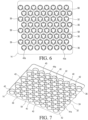
- base sections 46 may include apertures 58, as shown in Figs. 3 , 4 , and 6 .
- aperture shape should not be limiting.
- the term "aperture” should be broadly construed as any opening positioned in base sections 46, which is suitable for the passage of sterilizing agents and/or process agents.
- the aperture 58 may have a slot, square, oval, or other polygonal shape.
- the cover 14 may be attached to the piston nest assembly 20 with either an interference fit or a clearance fit, however a slight clearance fit is preferred.
- an interference fit the interior face 50 of the wall 42 of the cover 14 abuts against exterior surfaces of the cylindrical bodies 28 of the piston nest 10.
- the piston nest assembly 20 may alternatively be inserted into the cover 14 to have a clearance fit such that there is generally a small space between the interior face 50 of the wall 42 of the cover 14 and the exterior surfaces of the cylindrical bodies 28 of the piston nest 10.
- the open lower end 29 of the cylindrical body 28 preferably rests against the locators 48 and the interior face 49 of the cover 14.
- Figs. 8 to 13 show an exemplary embodiment of a cover 214 and a piston nest assembly 220, which does not belong to the invention.
- Fig. 8 shows a package 200 that includes the same piston nest 10, drug container piston array 12, and container 16, shown in Fig. 1 .
- the cover 214 has a different configuration such that rows or columns of a piston array or cylindrical bodies of a piston nest are positioned in a plurality of transversely elongated cover sections 234.
- Fig. 10 is a partially exploded view of the cover and piston nest assembly 220, shown in Fig. 9 .
- the cover 214 includes a plurality of transversely elongated cover sections 234 configured for positioning over rows or columns a drug container piston array 12, preferably with the piston array contained within a piston nest 10.
- Fig. 10 shows the cover 214 in alignment with the piston nest 10 and pistons 26 contained within respective nesting units 22 of the piston nest.
- Each respective cover section 234 includes an open base or upper end 238 and a closed capped or lower end 240.
- Chamfers 241, 243 may also be optionally included around the outer perimeter of the base end 238 and/or the inner edge 252 of the capped end 240. Chamfers located on the inner edge 252 may also serve to facilitate distribution of sterilizing and processing agents along the cover sections.
- a wall 242 extends between the base end 238 and the capped end 240 such that a cover section body 244 is formed, as shown particularly in Figs. 11 and 13 .
- cover sections 232 may be positioned to be laterally offset with respect to one another or in configured in rows, which are substantially aligned (i.e. not laterally offset).
- interconnecting cover web 246 Positioned between each cover section 234 and coupled to each base end 238 to extend around the cover is an interconnecting cover web 246.
- the interconnecting cover web 246 preferably has an outer perimeter 250 that is similar to that of the piston nest 10, as shown in Fig. 10 .
- Figs. 10 and 12 respectively show interior portions of the plurality of cover sections 234. Included within the interior of each cover section 234 is a plurality of locators 248, which are used to position and at least partially orient rows and/or columns of a piston array or a piston nest 10. In this configuration, the locators 248 are positioned at intervals along sidewalls 260, 262, 264, 266 and the bottom wall 268 of the cover section body 244.
- Fig. 10 shows a total of 18 locators 248 - one locator positioned on sidewalls 246, 266 and eight locators positioned on sidewalls 260, 262.
- Fig. 13 is a bottom perspective view of the cover 214, and particularly shows a plurality of cover reinforcements 254 positioned between cover sections 234.
- Individual cover reinforcements 254 are preferably integral with individual cover sections 234 such that the cover 214 provides structural support of rows and/or columns of the piston nest 10 after insertion into the cover 214.
- the cover reinforcements 254 are coupled to outer surfaces of the cover section bodies 244 and positioned at intervals transversely along the length of each cover section.
- the cover also include lateral cover reinforcements 255 coupled to end walls 235 and disposed between the outermost ends 270 of cover sections 234 (i.e. those closest to the outer perimeter 250).
- cover configurations 14, 214 described herein are not necessarily limited to materials used to manufacture piston nests (e.g. rigid or semi-rigid polymeric materials).
- Cover materials are, however, preferably polymeric such that they formed by molding and other similar manufacturing methods. Preferred materials are also suitable for use with processes used to sterilize piston nests.
Landscapes
- Health & Medical Sciences (AREA)
- Engineering & Computer Science (AREA)
- General Health & Medical Sciences (AREA)
- Hematology (AREA)
- Chemical & Material Sciences (AREA)
- Mechanical Engineering (AREA)
- Vascular Medicine (AREA)
- Anesthesiology (AREA)
- Biomedical Technology (AREA)
- Heart & Thoracic Surgery (AREA)
- Life Sciences & Earth Sciences (AREA)
- Animal Behavior & Ethology (AREA)
- Public Health (AREA)
- Veterinary Medicine (AREA)
- Chemical Kinetics & Catalysis (AREA)
- Clinical Laboratory Science (AREA)
- Analytical Chemistry (AREA)
- Infusion, Injection, And Reservoir Apparatuses (AREA)
Description
- The present invention relates to covers for drug container piston or plunger arrays or piston nests, and packages for cover and piston nest assemblies.
- For automated assembly purposes, individual drug container pistons are often positioned in array form, i.e. rows and columns. As discussed herein, a piston array may include any number of pistons and is not limited to a particular matrix configuration. Preferably, the arrangement of a piston array is maintained during automated assembly by positioning individual drug container pistons in a piston nest.
- A piston nest is typically a substantially planar tray that includes a plurality of individual nesting units. Each nesting unit is configured to receive a drug container piston. Exemplary piston nests are described in
US Patent No. 8,453,838 ,WO 2010/062602 A1 ,WO 2011/141549 A1 ,WO 2012/042291 A1 andUS 2004/009609 A1 . - During automated assembly of drug containers (e.g. syringes), a piston nest assembly, which includes the piston nest and a plurality pistons arranged in individual nesting units of the piston nest, is positioned above a similarly oriented tray with pre-filled drug container barrels. As assembly of the drug containers progresses, each piston from the piston nest is pressed into and aligned with an underlying drug container barrel, using automated means. Automated means may include, but is not limited to, mechanical pins and/or cams used to push each drug container piston out of a piston nest and into the underlying drug container barrel.
- To assure that all assembled parts of the drug container are suitable for use, it is important to properly package the piston nest assembly, and orient individual pistons within the nesting unit for sterilization, as well as various stoppering and filling methods. When piston nest assemblies are properly packaged, various contaminants are prevented from negatively impacting sterilization, integrity and/or usability as a part of a primary container.
- Current methods of packaging piston nest assemblies, however, do not include use of a cover or other structure that would protect and/or orient individual pistons for sterilization, stoppering, and filling of the drug container. Accordingly, there is a need for covers for drug container piston arrays and piston nests, as well as packages for cover and piston nest assemblies.
- The invention is defined in
claims 1 and 12. Advantageous embodiments are subject of the dependent claims. - In one preferred embodiment, a cover for a drug container piston array includes a plurality of cover sections configured for positioning over the drug container piston array. Each cover section includes a cover section body, having an open base end and a closed capped end, and a plurality of base sections positioned between the plurality of cover sections and coupled to each base end. Disposed within the cover section body are radially positioned locators placed in substantially equidistant intervals on inner surfaces of the cover section body.
- Packages for a cover and piston nest assembly may include either embodiment of the cover and a piston nest disposed within a container.
- The foregoing summary, as well as the following detailed description of preferred embodiments of the invention, will be better understood when read in conjunction with the appended drawings. For the purpose of illustrating the invention, there are shown in the drawings embodiments which are presently preferred. It should be understood, however, that the invention is not limited to the precise arrangements shown. In the drawings:
-
Fig. 1 is a perspective view of a package, including a first embodiment of a container and a cover and piston nest assembly in accordance with the present invention; -
Fig. 2 is a perspective view of the cover and piston nest assembly included in the package ofFig. 1 ; -
Fig. 3 is an enlarged exploded perspective view of the cover and piston nest assembly shown inFig. 2 ; -
Fig. 4 is a greatly enlarged top plan view of the cover ofFig. 3 , according to one preferred cover configuration; -
Fig. 5 is an enlarged cross-sectional elevational view of the cover and piston nest assembly shown inFig. 2 , taken along line 5-5; -
Fig. 6 is a top plan view of the cover for a drug container piston array shown inFig. 3 ; -
Fig. 7 is a bottom perspective view of the cover shown inFig. 6 ; -
Fig. 8 is a perspective view of a package, including an embodiment of a container and a cover and piston nest assembly, which does not belong to the invention; -
Fig. 9 is a perspective view of the cover and piston nest assembly included in the package ofFig. 8 ; -
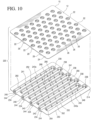
Fig. 10 is an enlarged exploded perspective view of the cover and piston nest assembly shown inFig. 9 ; -
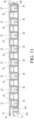
Fig. 11 is an enlarged cross-sectional elevational view of the cover and piston nest assembly shown inFig. 9 , taken along line 11-11; -
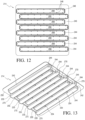
Fig. 12 is a top plan view of the cover for a drug container piston array shown inFig. 10 ; and -
Fig. 13 is a bottom perspective view of the cover shown inFig. 12 . - Reference will now be made in detail to the present embodiments of the invention illustrated in the accompanying drawings. Wherever possible, the same or like reference numbers will be used throughout the drawings to refer to the same or like features. It should be noted that the drawings are in simplified form and are not drawn to a precise scale. In reference to the disclosure herein, for purposes of convenience and clarity only, directional terms such as top, bottom, above, below, distal, and transverse, are used with respect to the accompanying drawings. Such directional terms used in conjunction with the following description of the drawings should not be construed to limit the scope of the invention in any manner not explicitly set forth herein. Unless specifically set forth herein, the terms "a", "an" and "the" are not limited to one element but instead should be read as meaning "at least one". The terminology includes the words noted above, derivatives thereof and words of similar import.
- Turning in detail to the drawings,
Figs. 1-13 show various configurations of covers and embodiments of piston nest assemblies and packages for covers and piston nest assemblies.Figs. 1-7 show apiston nest 10, a drugcontainer piston array 12, and acover 14, according to a first configuration, disposed within acontainer 16. Together these elements form apackage 100 for acover 14 and apiston nest assembly 20. - The
container 16 is preferably manufactured from one or more materials, which are suitable for sterilization and protection of a cover and a piston nest assembly 20 (Figs. 2 and9 ), particularly from contamination that could render a plurality ofpistons 26 contained in the assembly unsuitable for subsequent use/assembly with a drug container. Thecontainer 16 may be any known container, which is suitable for housing sterilized pistons. Container types include STERIBAGS® sterile containers and other pre-sterilized containers known to those skilled in the art.Figs. 2 and3 show thecover 14 and thepiston nest assembly 20 ofFig. 1 , whileFigs. 9 and10 show thecover 214 and thepiston nest assembly 220 ofFig. 8 . - Generally, a
piston nest 10, as shown particularly inFigs. 3 and10 , includes a plurality of spaced apartsingle nesting units 22, interconnected by anest web 24. In a preferred configuration, thepiston nest 10 can include one hundred spaced apartsingle nesting units 22. The piston nest 10, however, can be configured to include more or less than one hundrednesting units 22. Thepiston nest 10 can also include a piston 26 (Fig. 5 ) configured within each of the plurality of spaced apartsingle nesting units 22. - The
piston nest 10 is generally configured as a planar tray with thesingle nesting units 22 connected in a planar fashion by thenest web 24. While thepiston nest 10 is shown configured as a planar rectangular tray, thepiston nest 10 can alternatively be configured into any planar fashion suitable for its intended use. For example, the outer perimeter 25 of thepiston nest 10 may be configured as a square, a circle, an oval, an octagon, or various other shapes. - The
piston nest 10 is preferably formed from one or more rigid materials such as rigid or semi-rigid polymeric materials, including, but not limited to, polyethylene, polycarbonate, polypropylene and/or composite combinations of materials. The chosen materials of construction preferably maintain the integrity of the pistons as well as not deform to a point of affecting machinability. Polypropylene, however, is preferred as the material forpiston nests 10 because materials such as polypropylene are able to withstand autoclaving processes better than piston nests formed from other polymeric materials. Alternatively, as radiation is another preferred method of sterilization, a material which is stable following exposure to standard radiation sterilization processes (e.g., gamma radiation), such as gamma stable polypropylene, is preferred. Other suitable materials will be apparent to those skilled in the art - As shown particularly in
Fig. 5 , asingle nesting unit 22 includes a generally hollowcylindrical body 28, also known as a chimney, which extends distally from (below) theweb 24, to form an openlower end 29. Thenesting unit 22 may also include one ormore retention members 30, which are used to retainindividual pistons 26 withincylindrical bodies 28 of thepiston nest 10. In the current embodiment, theretention members 30 comprise diametrical protrusions that inwardly extend toward a central axis β of thecylindrical body 28 such that anindividual piston 26 is retained within thecylindrical body 28 with a generally vertical orientation (parallel to the axis β). Further details on exemplary piston nest configurations are shown and described inUS Patent No. 8,453,838 . As such, the piston nest configuration shown and described herein should not be construed as limiting. - The purpose of the cover configurations and assembly and package embodiments, shown and described herein, is to protect interior portions of the
pistons 26 and/or the hollowcylindrical bodies 28 of thepiston nest 10 from a variety of potential contaminants. Such contaminants are of the type that would otherwise infiltrate the interior portions of thepistons 26 and the hollowcylindrical body 28. Contaminants may come from a variety of sources, including, but not limited to packaging materials and air particles. - The cover configurations shown and described herein are also used to provide at least some additional structural support to the
piston nest 10. Preferably, each cover configuration provides at least some additional structural support that would assist in alleviating warping ofpiston nests 10 that is known to occur over time. Cover configurations may also be such that movement of the cylindrical bodies/chimneys 28 of thepiston nest 10 is restricted. As such, the covers may have an interference fit with thepiston nest 10 orpistons 26 included in a piston array. -
Fig. 3 is a partially exploded perspective view of thecover 14 and thepiston nest assembly 20, shown inFig. 2 . More particularly inFig. 3 , a first configuration of acover 14 for thepiston nest 10 is shown. Thecover 14 is particularly suited for positioning over (but on the bottom of) the open lower ends 29 of thepiston nest 10, as particularly shown inFig. 5 . - Referring to
Figs. 3 ,4 ,6, and 7 , thecover 14 includes a plurality ofcover sections 34 configured for positioning over a drugcontainer piston array 12, preferably with thepiston array 12 contained within apiston nest 10.Fig. 3 shows thecover 14 in alignment with thepiston nest 10 andpistons 26 contained withinrespective nesting units 22 of thepiston nest 10. Eachindividual cover section 34 includes anelongated cover body 36, having an open base orupper end 38, as particularly shown inFigs. 3 ,4 , and6 , and a closed capped end bottom 40, as particularly shown inFig. 7 . Chamfers 41 (Fig. 4 ), 43a (inner chamfer,Fig. 4 ), 43b (outer chamfer,Fig. 7 ), may optionally be included around thebase end 38 and/or the capped end 40 (interior portion 41, shown inFig. 4 ).Chamfers base end 38 and/or the cappedend 40 to facilitate insertion of thepiston nest 14 into thecover 14. A wall 42 (Fig. 4 ) extends between thebase end 38 and the cappedend 40 such that theelongated cover body 36 is formed, as shown particularly inFig. 7 . - Positioned between each
individual cover section 34 and coupled to eachbase end 38 is a plurality ofbase sections 46, as shown particularly inFigs. 3 and4 . Thebase sections 46 are used to interconnect thecover sections 34. Upon formation of thecover 14, thecover sections 34 may be positioned to be laterally offset with respect to one another or configured in substantially aligned rows and columns, which are not offset with respect to one another. Cover section positioning, however, is preferably such that thecover 14 can be positioned over the open lower ends 29 of thecylindrical bodies 28 of various piston nest arrangements. -
Figs. 3 and6 , respectively show interior portions of the plurality ofcover sections 34. Included within eachcover section 34 is a plurality oflocators 48, which are used to position and at least partially orient thecylindrical bodies 28 of thepiston nest 10. Preferably, thelocators 48 are positioned within eachcover section 34 such that the orientation of thecylindrical bodies 28 is centered with respect to a central axis B. Thelocators 48 are preferably integrally incorporated into eachcover section 34 and manufactured from materials that are the same as thecover 14. Preferably, the configuration of thelocators 48 is such that each locator frictionally fits against and engages eachcylindrical body 28 of eachpiston nest 10. - In the present cover configuration, three
locators 48 are radially positioned on interior faces 49, 50 of the cover section body 44, as shown inFig. 4 . Thelocators 48 function to orient and locate thecylindrical bodies 28 of thepiston nest 10. Preferably, eachrespective locator 48 is disposed on aninner edge 52 and positioned between the distal end of thewall 42 and the cappedend 40 of thecylindrical body 28. The plurality oflocators 48 are also radially positioned at substantially equidistant intervals around the inner diameter of the cover section body 44.Fig. 4 showsindividual piston locators 48 positioned at an angle α, with respect to one another, which is approximately 120° (degrees). Fewer ormore locators 48 may be positioned within the cover section body 44, depending upon various factors, including the piston diameters. Preferably, the outer shape or perimeter of thecover 14, however, is complementary in shape and size to the outer shape or perimeter of apiston nest 10. -
Fig. 7 is a bottom perspective view of thecover 14, which includes a plurality ofcover reinforcements 54 positioned between cover sections.Individual cover reinforcements 54 are preferably integral withindividual cover sections 34 such that thecover 14 provides structural support of thepiston nest 10 after insertion into thecover 14. Preferably, outer surfaces of the innercover section bodies 44a have at least fivecover reinforcements 54 positioned radially in substantially equidistant intervals around the outer diameter of each innercover section body 44a. Outer surfaces of outer cover section bodies 44b have cover sections that inwardly extend toward the center of thecover 14 and at least onecover reinforcement 54 positioned on a side of the cover section body 44. The overall configuration of thecover 14 from a bottom perspective due to the positioning of the cover section bodies 44 and thecover reinforcements 54 results in a honeycomb-like configuration, as shown particularly inFig. 7 . - To facilitate the passage of sterilizing agents and/or process agents (e.g. steam from an autoclave) through the
cover 14 and thepiston nest 10,base sections 46 may includeapertures 58, as shown inFigs. 3 ,4 , and6 . Although shown with a circular shape, the aperture shape should not be limiting. As used herein, the term "aperture" should be broadly construed as any opening positioned inbase sections 46, which is suitable for the passage of sterilizing agents and/or process agents. As such, theaperture 58 may have a slot, square, oval, or other polygonal shape. - The
cover 14 may be attached to thepiston nest assembly 20 with either an interference fit or a clearance fit, however a slight clearance fit is preferred. With an interference fit, theinterior face 50 of thewall 42 of thecover 14 abuts against exterior surfaces of thecylindrical bodies 28 of thepiston nest 10. Thepiston nest assembly 20 may alternatively be inserted into thecover 14 to have a clearance fit such that there is generally a small space between theinterior face 50 of thewall 42 of thecover 14 and the exterior surfaces of thecylindrical bodies 28 of thepiston nest 10. However, with either an interference fit or a clearance fit, the openlower end 29 of thecylindrical body 28 preferably rests against thelocators 48 and theinterior face 49 of thecover 14. -
Figs. 8 to 13 show an exemplary embodiment of acover 214 and apiston nest assembly 220, which does not belong to the invention.Fig. 8 shows apackage 200 that includes thesame piston nest 10, drugcontainer piston array 12, andcontainer 16, shown inFig. 1 . Thecover 214, however, has a different configuration such that rows or columns of a piston array or cylindrical bodies of a piston nest are positioned in a plurality of transversely elongatedcover sections 234.Fig. 10 is a partially exploded view of the cover andpiston nest assembly 220, shown inFig. 9 . - The
cover 214 includes a plurality of transversely elongatedcover sections 234 configured for positioning over rows or columns a drugcontainer piston array 12, preferably with the piston array contained within apiston nest 10.Fig. 10 shows thecover 214 in alignment with thepiston nest 10 andpistons 26 contained withinrespective nesting units 22 of the piston nest. Eachrespective cover section 234 includes an open base orupper end 238 and a closed capped orlower end 240.Chamfers 241, 243 may also be optionally included around the outer perimeter of thebase end 238 and/or theinner edge 252 of the cappedend 240. Chamfers located on theinner edge 252 may also serve to facilitate distribution of sterilizing and processing agents along the cover sections. - A
wall 242 extends between thebase end 238 and the cappedend 240 such that acover section body 244 is formed, as shown particularly inFigs. 11 and13 . Upon formation of thecover 214, cover sections 232 may be positioned to be laterally offset with respect to one another or in configured in rows, which are substantially aligned (i.e. not laterally offset). - Positioned between each
cover section 234 and coupled to eachbase end 238 to extend around the cover is an interconnectingcover web 246. The interconnectingcover web 246 preferably has anouter perimeter 250 that is similar to that of thepiston nest 10, as shown inFig. 10 . -
Figs. 10 and12 , respectively show interior portions of the plurality ofcover sections 234. Included within the interior of eachcover section 234 is a plurality oflocators 248, which are used to position and at least partially orient rows and/or columns of a piston array or apiston nest 10. In this configuration, thelocators 248 are positioned at intervals alongsidewalls bottom wall 268 of thecover section body 244. -
Fig. 10 shows a total of 18 locators 248 - one locator positioned onsidewalls sidewalls cover section body 244, however, should not be construed as limiting. Fewer ormore locators 248 may be positioned within the cover section body, depending, in part, on the total number ofpistons 26 and/orcylindrical bodies 28 of thepiston nest 10. -
Fig. 13 is a bottom perspective view of thecover 214, and particularly shows a plurality ofcover reinforcements 254 positioned betweencover sections 234.Individual cover reinforcements 254 are preferably integral withindividual cover sections 234 such that thecover 214 provides structural support of rows and/or columns of thepiston nest 10 after insertion into thecover 214. Here, thecover reinforcements 254 are coupled to outer surfaces of thecover section bodies 244 and positioned at intervals transversely along the length of each cover section. The cover also includelateral cover reinforcements 255 coupled to endwalls 235 and disposed between the outermost ends 270 of cover sections 234 (i.e. those closest to the outer perimeter 250). - Materials used in the manufacture of the
cover configurations
Claims (13)
- A cover (14) for a drug container piston array (12) or piston nest (10) including a plurality of spaced apart nesting units (22) interconnected by a nest web (24), and extending distally therefrom, each nesting unit (22) for retaining a piston (26) therein, the cover (14) comprising:a plurality of cover sections (34) configured for positioning over the drug container piston array (12), each cover section (34) comprising an elongated cover section body (44), having an open base end (38), a closed capped end (40), a wall (42) extending between the base end (38) and the capped end (40) and a plurality of piston locators (48); and a plurality of base sections (46) positioned between the plurality of cover sections (34) and coupled to each base end (38),characterized in thatthe plurality of piston locators (48) are positioned in radial intervals along an interior face (50) of the wall (42) of each elongated cover body (44), each piston locator (48) being configured and positioned to engage and orient the nesting units (22) of the piston nest (10) within corresponding elongated cover bodies (36).
- The cover (14) of claim 1, wherein at least two of the plurality of cover sections (34) are laterally offset with respect to one another.
- The cover (14) of claim 1, further comprising a plurality of cover reinforcements (54) positioned between at least two of the plurality of cover sections (34).
- The cover (14) of claim 3, wherein at least one of the plurality of cover reinforcements (54) is coupled to an outer wall surface of each of the plurality of cover sections (34).
- The cover (14) of claim 1, further comprising at least one cover reinforcement (54) positioned between at least two of the plurality of cover sections (34).
- The cover (14) of claim 5, wherein the at least one cover reinforcement (54) is coupled to an outer wall surface of at least one cover section (34).
- The cover (14) of claim 5, wherein the at least one cover reinforcement (54) is integral with at least one cover section (34).
- The cover (14) of claim 1, wherein the plurality of piston locators (48) are integrally incorporated into each cover section (34).
- The cover (14) of claim 1, wherein at least one of the open base end (38) and the closed capped end (40) of the elongated cover bodies (36) is chamfered.
- The cover (14) of claim 1, further comprising at least one aperture (58) disposed in at least one of the base sections (46) to facilitate passage of at least one of a sterilizing agent and a process agent through the cover.
- A packaging assembly for a drug container piston array (12), comprising:a package (100);a drug container piston array (12) disposed within the package (100); andthe cover (14) of claim 1 disposed within the package (100) and positioned over the drug container piston array (12) disposed within the package to protect the array of pistons.
- A method of covering a drug container piston array (12), comprising:
inserting a plurality of drug container pistons (26) within a plurality of spaced apart nesting units (22) of a drug container piston array (12);
positioning the cover (14) of claim 1 over the drug container piston array (12) toprevent infiltration of at least some contaminants into the interior of at least some of the drug container pistons (26). - The method of claim 12, further comprising the step of inserting the drug container piston array (12) and the cover (14) thereon into a package (100), forming a packaging assembly.
Applications Claiming Priority (1)
| Application Number | Priority Date | Filing Date | Title |
|---|---|---|---|
| PCT/US2015/010826 WO2016111698A1 (en) | 2015-01-09 | 2015-01-09 | Covers for drug container piston arrays or piston nests and packages for cover and piston nest assemblies |
Publications (2)
| Publication Number | Publication Date |
|---|---|
| EP3242694A1 EP3242694A1 (en) | 2017-11-15 |
| EP3242694B1 true EP3242694B1 (en) | 2025-03-05 |
Family
ID=52396846
Family Applications (1)
| Application Number | Title | Priority Date | Filing Date |
|---|---|---|---|
| EP15701285.7A Active EP3242694B1 (en) | 2015-01-09 | 2015-01-09 | Covers for drug container piston arrays or piston nests and packages for cover and piston nest assemblies |
Country Status (6)
| Country | Link |
|---|---|
| US (1) | US10434242B2 (en) |
| EP (1) | EP3242694B1 (en) |
| JP (1) | JP6524238B2 (en) |
| CN (1) | CN107427625B (en) |
| ES (1) | ES3023214T3 (en) |
| WO (1) | WO2016111698A1 (en) |
Families Citing this family (21)
| Publication number | Priority date | Publication date | Assignee | Title |
|---|---|---|---|---|
| US12515832B2 (en) * | 2013-08-16 | 2026-01-06 | Vanrx Pharmasystems Inc. | Method, device and system for filling pharmaceutical containers |
| CN107427625B (en) * | 2015-01-09 | 2020-06-19 | 维斯特医药服务有限公司 | Caps for drug container plunger arrays or plunger sleeves and packaging for cap and plunger sleeve assemblies |
| DE102016123147A1 (en) * | 2016-11-30 | 2018-05-30 | Schott Ag | Support structure for simultaneously holding a plurality of vials, use thereof, and methods of treating such vials |
| USD838004S1 (en) * | 2017-01-25 | 2019-01-08 | Arizona Board Of Regents On Behalf Of Arizona State University | Aliquot tray |
| IT201700046565A1 (en) * | 2017-04-28 | 2018-10-28 | Nuova Ompi Srl | Structure for packaging containers for pharmaceutical use |
| US11161633B2 (en) | 2017-12-22 | 2021-11-02 | West Pharmaceutical Services, Inc. | Packaging system for aseptic filling of small volume vials |
| JP6694900B2 (en) | 2018-02-08 | 2020-05-20 | 株式会社大協精工 | Holding member and syringe piston packaging structure |
| IT201800003376A1 (en) | 2018-03-08 | 2019-09-08 | Nuova Ompi Srl | STRUCTURE FOR THE PACKAGING OF CONTAINERS FOR PHARMACEUTICAL USE |
| EP3646950B1 (en) * | 2018-10-31 | 2023-08-23 | SCHOTT Pharma Schweiz AG | Transport unit and packaging structure for transporting and storing a plurality of containers for substances for pharmaceutical, medical or cosmetic uses |
| DE102018128817A1 (en) * | 2018-11-16 | 2020-05-20 | Schott Schweiz Ag | Holding structure for simultaneously holding a plurality of containers for substances for pharmaceutical, medical or cosmetic applications, transport structures and transport or packaging containers with the same |
| US11701232B2 (en) * | 2019-01-15 | 2023-07-18 | University Of Maryland, College Park | Acellular bioactive scaffold device and methods of fabrication and treatment relating thereto |
| US11161671B2 (en) * | 2019-07-18 | 2021-11-02 | Daikyo Seiko Ltd. | Medical device container |
| EP3791906B1 (en) * | 2019-09-11 | 2024-03-27 | SCHOTT Pharma Schweiz AG | Charge device having a positioning means and a process for closing receptacles with venting |
| US12098018B2 (en) * | 2021-01-15 | 2024-09-24 | Oyster Point Pharma, Inc. | Nesting structures for storage, transport, and assembly of drug dispensers and containers |
| CN116744988B (en) * | 2021-01-26 | 2026-07-10 | 贝克顿迪金森法国公司 | Inlay set |
| IT202200015591A1 (en) * | 2022-07-25 | 2024-01-25 | Nuova Ompi S R L Unipersonale | Device for supporting a plurality of containers for pharmaceutical use to be moved in a processing line |
| JPWO2024105915A1 (en) * | 2022-11-14 | 2024-05-23 | ||
| EP4516334A1 (en) * | 2023-09-04 | 2025-03-05 | Becton, Dickinson and Company | Medical container nest with reduced warpage and residual stress |
| IT202300021390A1 (en) * | 2023-10-13 | 2025-04-13 | Biopap S R L | METHOD AND ASSEMBLY GROUP FOR MAKING TRAYS |
| USD1119282S1 (en) * | 2024-04-15 | 2026-03-24 | Schott Pharma Schweiz Ag | Portion of a holding structure for pharmaceutical containers |
| FR3162427B1 (en) * | 2024-05-27 | 2026-04-24 | A Raymond Et Cie | Packaging tray for caps intended for sealing pharmaceutical bottles |
Citations (1)
| Publication number | Priority date | Publication date | Assignee | Title |
|---|---|---|---|---|
| US20040009609A1 (en) * | 1998-11-12 | 2004-01-15 | Atrix Laboratories, Inc. | Method for lyophilizing an active agent |
Family Cites Families (31)
| Publication number | Priority date | Publication date | Assignee | Title |
|---|---|---|---|---|
| US3195770A (en) * | 1963-02-18 | 1965-07-20 | Holley Plastics Company | Plastic capsule packaging |
| US3469686A (en) * | 1967-02-08 | 1969-09-30 | Monsanto Co | Retaining trays for semiconductor wafers and the like |
| US3589511A (en) * | 1969-08-13 | 1971-06-29 | Owens Illinois Inc | Package and tray for tubes or the like |
| US3982655A (en) * | 1972-08-04 | 1976-09-28 | Gunther Kaupert | Nestable compartmentalized trays |
| US3946864A (en) * | 1974-07-01 | 1976-03-30 | Hutson Jearld L | Semiconductor chip package |
| US4838417A (en) * | 1988-08-18 | 1989-06-13 | Chrysler Motors Corporation | Storage pack comprising at least two stacked and nested trays each loaded with a plurality of semi-circular split ring bearing halves |
| US5826712A (en) * | 1992-09-29 | 1998-10-27 | Oy Hartwall Ab | Base plate for a bottle package |
| US5590805A (en) * | 1994-02-08 | 1997-01-07 | Ultra Pac, Inc. | Fruit box |
| US6193088B1 (en) * | 1996-02-26 | 2001-02-27 | Monty E. Vincent | Flask vent and method of making same |
| US6021913A (en) * | 1996-12-17 | 2000-02-08 | Mcgrath; Patrick James | Tray system for beverage cans and a beverage can tray |
| CA2337730C (en) * | 2000-02-22 | 2005-05-17 | Tekni-Plex, Inc. | Packing tray |
| US20050011898A1 (en) * | 2002-06-18 | 2005-01-20 | Van Handel Gerald J. | Sealable portion cups and lids therefor |
| US7478946B2 (en) | 2003-01-06 | 2009-01-20 | Covidien Ag | Probe cover cassette with improved probe cover support |
| ES2290426T3 (en) * | 2003-01-06 | 2008-02-16 | Covidien Ag | PROBE COVER FOR A TIMPANIC THERMOMETER. |
| US8100263B2 (en) * | 2004-07-01 | 2012-01-24 | West Pharmaceutical Services, Inc. | Vacuum package system |
| MX2007000297A (en) * | 2004-07-01 | 2007-08-16 | West Pharm Serv Inc | Vacuum package system and method. |
| US7909164B2 (en) * | 2005-04-01 | 2011-03-22 | Pactiv Corporation | Nestable lid for packaging systems |
| WO2007099649A1 (en) * | 2006-02-28 | 2007-09-07 | Daikyo Seiko, Ltd. | Piston nest for injector |
| US8453838B2 (en) | 2008-10-28 | 2013-06-04 | West Pharmaceutical Services, Inc. | Syringe piston nest for the manufacture of pre filled syringe |
| IT1393082B1 (en) * | 2009-01-27 | 2012-04-11 | Semafra S A | PACKAGING STRUCTURE OF CONTAINERS FOR PHARMACEUTICAL USE |
| US8047373B2 (en) * | 2009-05-11 | 2011-11-01 | Murphy Michael P | Suspended utensil storage system and method |
| GB201004102D0 (en) * | 2010-03-12 | 2010-04-28 | Liversidge Barry P | Syringe barrels and handling systems |
| EP2636418B1 (en) | 2010-05-12 | 2019-07-31 | Sanofi-Aventis Deutschland GmbH | Workpiece carrier for transporting and/or storing components of drug delivery devices |
| EP2621552B1 (en) * | 2010-09-28 | 2016-06-29 | Becton Dickinson France | Packaging for cylindrical containers |
| DE102011104300A1 (en) * | 2011-03-18 | 2012-09-20 | Schott Schweiz Ag | Support plate and transport and / or storage device for pharmaceutical containers |
| EP2818190B1 (en) * | 2012-02-20 | 2016-11-02 | Terumo Kabushiki Kaisha | Medical device packaging body |
| US8545914B1 (en) * | 2012-05-31 | 2013-10-01 | Focus Products Group International, Llc | Food product carrier set |
| IN2015DN00104A (en) | 2012-06-26 | 2015-05-29 | Terumo Corp | |
| US8826712B1 (en) * | 2013-03-15 | 2014-09-09 | Ford Global Technologies, Llc | Pressure sequence process for hydro-forming an extruded structural tube |
| US9539757B2 (en) * | 2013-06-26 | 2017-01-10 | Tekni-Plex, Inc. | Packing tray having cell pockets with expandable sidewalls and floating base, and method of manufacture |
| CN107427625B (en) * | 2015-01-09 | 2020-06-19 | 维斯特医药服务有限公司 | Caps for drug container plunger arrays or plunger sleeves and packaging for cap and plunger sleeve assemblies |
-
2015
- 2015-01-09 CN CN201580072780.3A patent/CN107427625B/en active Active
- 2015-01-09 EP EP15701285.7A patent/EP3242694B1/en active Active
- 2015-01-09 JP JP2017535821A patent/JP6524238B2/en active Active
- 2015-01-09 ES ES15701285T patent/ES3023214T3/en active Active
- 2015-01-09 WO PCT/US2015/010826 patent/WO2016111698A1/en not_active Ceased
- 2015-01-09 US US15/541,182 patent/US10434242B2/en active Active
Patent Citations (1)
| Publication number | Priority date | Publication date | Assignee | Title |
|---|---|---|---|---|
| US20040009609A1 (en) * | 1998-11-12 | 2004-01-15 | Atrix Laboratories, Inc. | Method for lyophilizing an active agent |
Also Published As
| Publication number | Publication date |
|---|---|
| US20170348476A1 (en) | 2017-12-07 |
| US10434242B2 (en) | 2019-10-08 |
| WO2016111698A1 (en) | 2016-07-14 |
| CN107427625B (en) | 2020-06-19 |
| ES3023214T3 (en) | 2025-05-30 |
| JP2018501012A (en) | 2018-01-18 |
| CN107427625A (en) | 2017-12-01 |
| EP3242694A1 (en) | 2017-11-15 |
| JP6524238B2 (en) | 2019-06-05 |
Similar Documents
| Publication | Publication Date | Title |
|---|---|---|
| US10434242B2 (en) | Covers for drug container piston arrays or piston nests and packages for cover and piston nest assemblies | |
| KR102789439B1 (en) | Supporting structure for concurrently supporting a plurality of containers for substances for pharmaceutical, medical or cosmetic applications, and transport structure comprising the same | |
| EP2364171B1 (en) | Syringe piston nest for the manufacture of pre filled syringe | |
| US11286095B2 (en) | Supporting structure for concurrently supporting a plurality of containers for substances for pharmaceutical, medical or cosmetic applications, transport structure and transport or packaging container comprising the same | |
| KR102009119B1 (en) | Container Holding Member and Medical Container Set | |
| CN110127180B (en) | Holding member and packaging structure for component for medicine container | |
| EP3762303B1 (en) | Structure for packaging containers for pharmaceutical use | |
| DE102013112167A1 (en) | Support structure for simultaneously holding a plurality of containers for substances for medical, pharmaceutical or cosmetic applications as well as transport and packaging containers with self and method | |
| EP3381828A1 (en) | Supporting structure for supporting a plurality of containers for substances for medical, pharmaceutical or cosmetic applications, combined supporting structure and transport and packaging container comprising the same | |
| US10064786B2 (en) | Container-holding tray | |
| CN110099706A (en) | Holding structure for simultaneously holding multiple containers of substances for pharmaceutical, medical or cosmetic applications, transport structure and transport or packaging container comprising the same | |
| EP3999437B1 (en) | Structure for the packaging of primary containers for pharmaceutical use | |
| EP2659981B1 (en) | Transport or packaging container with a support structure for simultaneously holding a plurality of containers for medical, pharmaceutical or cosmetic applications and method for treating such containers | |
| EP4516334A1 (en) | Medical container nest with reduced warpage and residual stress | |
| KR20250152012A (en) | Cartridge nest, which features integrated centering of the cartridges |
Legal Events
| Date | Code | Title | Description |
|---|---|---|---|
| STAA | Information on the status of an ep patent application or granted ep patent |
Free format text: STATUS: THE INTERNATIONAL PUBLICATION HAS BEEN MADE |
|
| PUAI | Public reference made under article 153(3) epc to a published international application that has entered the european phase |
Free format text: ORIGINAL CODE: 0009012 |
|
| STAA | Information on the status of an ep patent application or granted ep patent |
Free format text: STATUS: REQUEST FOR EXAMINATION WAS MADE |
|
| 17P | Request for examination filed |
Effective date: 20170627 |
|
| AK | Designated contracting states |
Kind code of ref document: A1 Designated state(s): AL AT BE BG CH CY CZ DE DK EE ES FI FR GB GR HR HU IE IS IT LI LT LU LV MC MK MT NL NO PL PT RO RS SE SI SK SM TR |
|
| AX | Request for extension of the european patent |
Extension state: BA ME |
|
| DAX | Request for extension of the european patent (deleted) | ||
| STAA | Information on the status of an ep patent application or granted ep patent |
Free format text: STATUS: EXAMINATION IS IN PROGRESS |
|
| 17Q | First examination report despatched |
Effective date: 20210326 |
|
| REG | Reference to a national code |
Ref country code: DE Ref legal event code: R079 Free format text: PREVIOUS MAIN CLASS: A61M0005000000 Ipc: B01L0003000000 Ref document number: 602015091148 Country of ref document: DE |
|
| GRAP | Despatch of communication of intention to grant a patent |
Free format text: ORIGINAL CODE: EPIDOSNIGR1 |
|
| STAA | Information on the status of an ep patent application or granted ep patent |
Free format text: STATUS: GRANT OF PATENT IS INTENDED |
|
| RIC1 | Information provided on ipc code assigned before grant |
Ipc: B65D 71/70 20060101ALI20240730BHEP Ipc: A61M 5/00 20060101ALI20240730BHEP Ipc: B65D 25/10 20060101ALI20240730BHEP Ipc: B01L 3/00 20060101AFI20240730BHEP |
|
| INTG | Intention to grant announced |
Effective date: 20240816 |
|
| GRAS | Grant fee paid |
Free format text: ORIGINAL CODE: EPIDOSNIGR3 |
|
| GRAA | (expected) grant |
Free format text: ORIGINAL CODE: 0009210 |
|
| STAA | Information on the status of an ep patent application or granted ep patent |
Free format text: STATUS: THE PATENT HAS BEEN GRANTED |
|
| AK | Designated contracting states |
Kind code of ref document: B1 Designated state(s): AL AT BE BG CH CY CZ DE DK EE ES FI FR GB GR HR HU IE IS IT LI LT LU LV MC MK MT NL NO PL PT RO RS SE SI SK SM TR |
|
| REG | Reference to a national code |
Ref country code: GB Ref legal event code: FG4D |
|
| REG | Reference to a national code |
Ref country code: CH Ref legal event code: EP |
|
| REG | Reference to a national code |
Ref country code: IE Ref legal event code: FG4D |
|
| REG | Reference to a national code |
Ref country code: DE Ref legal event code: R096 Ref document number: 602015091148 Country of ref document: DE |
|
| REG | Reference to a national code |
Ref country code: ES Ref legal event code: FG2A Ref document number: 3023214 Country of ref document: ES Kind code of ref document: T3 Effective date: 20250530 |
|
| PG25 | Lapsed in a contracting state [announced via postgrant information from national office to epo] |
Ref country code: RS Free format text: LAPSE BECAUSE OF FAILURE TO SUBMIT A TRANSLATION OF THE DESCRIPTION OR TO PAY THE FEE WITHIN THE PRESCRIBED TIME-LIMIT Effective date: 20250605 |
|
| PG25 | Lapsed in a contracting state [announced via postgrant information from national office to epo] |
Ref country code: FI Free format text: LAPSE BECAUSE OF FAILURE TO SUBMIT A TRANSLATION OF THE DESCRIPTION OR TO PAY THE FEE WITHIN THE PRESCRIBED TIME-LIMIT Effective date: 20250305 |
|
| REG | Reference to a national code |
Ref country code: NL Ref legal event code: MP Effective date: 20250305 |
|
| REG | Reference to a national code |
Ref country code: LT Ref legal event code: MG9D |
|
| PG25 | Lapsed in a contracting state [announced via postgrant information from national office to epo] |
Ref country code: NO Free format text: LAPSE BECAUSE OF FAILURE TO SUBMIT A TRANSLATION OF THE DESCRIPTION OR TO PAY THE FEE WITHIN THE PRESCRIBED TIME-LIMIT Effective date: 20250605 |
|
| PG25 | Lapsed in a contracting state [announced via postgrant information from national office to epo] |
Ref country code: HR Free format text: LAPSE BECAUSE OF FAILURE TO SUBMIT A TRANSLATION OF THE DESCRIPTION OR TO PAY THE FEE WITHIN THE PRESCRIBED TIME-LIMIT Effective date: 20250305 |
|
| PG25 | Lapsed in a contracting state [announced via postgrant information from national office to epo] |
Ref country code: LV Free format text: LAPSE BECAUSE OF FAILURE TO SUBMIT A TRANSLATION OF THE DESCRIPTION OR TO PAY THE FEE WITHIN THE PRESCRIBED TIME-LIMIT Effective date: 20250305 |
|
| PG25 | Lapsed in a contracting state [announced via postgrant information from national office to epo] |
Ref country code: GR Free format text: LAPSE BECAUSE OF FAILURE TO SUBMIT A TRANSLATION OF THE DESCRIPTION OR TO PAY THE FEE WITHIN THE PRESCRIBED TIME-LIMIT Effective date: 20250606 Ref country code: BG Free format text: LAPSE BECAUSE OF FAILURE TO SUBMIT A TRANSLATION OF THE DESCRIPTION OR TO PAY THE FEE WITHIN THE PRESCRIBED TIME-LIMIT Effective date: 20250305 |
|
| REG | Reference to a national code |
Ref country code: AT Ref legal event code: MK05 Ref document number: 1772441 Country of ref document: AT Kind code of ref document: T Effective date: 20250305 |
|
| PG25 | Lapsed in a contracting state [announced via postgrant information from national office to epo] |
Ref country code: NL Free format text: LAPSE BECAUSE OF FAILURE TO SUBMIT A TRANSLATION OF THE DESCRIPTION OR TO PAY THE FEE WITHIN THE PRESCRIBED TIME-LIMIT Effective date: 20250305 |
|
| PG25 | Lapsed in a contracting state [announced via postgrant information from national office to epo] |
Ref country code: SE Free format text: LAPSE BECAUSE OF FAILURE TO SUBMIT A TRANSLATION OF THE DESCRIPTION OR TO PAY THE FEE WITHIN THE PRESCRIBED TIME-LIMIT Effective date: 20250305 |
|
| PG25 | Lapsed in a contracting state [announced via postgrant information from national office to epo] |
Ref country code: SM Free format text: LAPSE BECAUSE OF FAILURE TO SUBMIT A TRANSLATION OF THE DESCRIPTION OR TO PAY THE FEE WITHIN THE PRESCRIBED TIME-LIMIT Effective date: 20250305 |
|
| PG25 | Lapsed in a contracting state [announced via postgrant information from national office to epo] |
Ref country code: PT Free format text: LAPSE BECAUSE OF FAILURE TO SUBMIT A TRANSLATION OF THE DESCRIPTION OR TO PAY THE FEE WITHIN THE PRESCRIBED TIME-LIMIT Effective date: 20250707 |
|
| PG25 | Lapsed in a contracting state [announced via postgrant information from national office to epo] |
Ref country code: PL Free format text: LAPSE BECAUSE OF FAILURE TO SUBMIT A TRANSLATION OF THE DESCRIPTION OR TO PAY THE FEE WITHIN THE PRESCRIBED TIME-LIMIT Effective date: 20250305 |
|
| PG25 | Lapsed in a contracting state [announced via postgrant information from national office to epo] |
Ref country code: AT Free format text: LAPSE BECAUSE OF FAILURE TO SUBMIT A TRANSLATION OF THE DESCRIPTION OR TO PAY THE FEE WITHIN THE PRESCRIBED TIME-LIMIT Effective date: 20250305 |
|
| PG25 | Lapsed in a contracting state [announced via postgrant information from national office to epo] |
Ref country code: EE Free format text: LAPSE BECAUSE OF FAILURE TO SUBMIT A TRANSLATION OF THE DESCRIPTION OR TO PAY THE FEE WITHIN THE PRESCRIBED TIME-LIMIT Effective date: 20250305 Ref country code: CZ Free format text: LAPSE BECAUSE OF FAILURE TO SUBMIT A TRANSLATION OF THE DESCRIPTION OR TO PAY THE FEE WITHIN THE PRESCRIBED TIME-LIMIT Effective date: 20250305 |
|
| PG25 | Lapsed in a contracting state [announced via postgrant information from national office to epo] |
Ref country code: RO Free format text: LAPSE BECAUSE OF FAILURE TO SUBMIT A TRANSLATION OF THE DESCRIPTION OR TO PAY THE FEE WITHIN THE PRESCRIBED TIME-LIMIT Effective date: 20250305 |
|
| PG25 | Lapsed in a contracting state [announced via postgrant information from national office to epo] |
Ref country code: SK Free format text: LAPSE BECAUSE OF FAILURE TO SUBMIT A TRANSLATION OF THE DESCRIPTION OR TO PAY THE FEE WITHIN THE PRESCRIBED TIME-LIMIT Effective date: 20250305 |
|
| PG25 | Lapsed in a contracting state [announced via postgrant information from national office to epo] |
Ref country code: IS Free format text: LAPSE BECAUSE OF FAILURE TO SUBMIT A TRANSLATION OF THE DESCRIPTION OR TO PAY THE FEE WITHIN THE PRESCRIBED TIME-LIMIT Effective date: 20250705 |
|
| REG | Reference to a national code |
Ref country code: DE Ref legal event code: R097 Ref document number: 602015091148 Country of ref document: DE |
|
| PLBE | No opposition filed within time limit |
Free format text: ORIGINAL CODE: 0009261 |
|
| STAA | Information on the status of an ep patent application or granted ep patent |
Free format text: STATUS: NO OPPOSITION FILED WITHIN TIME LIMIT |
|
| PG25 | Lapsed in a contracting state [announced via postgrant information from national office to epo] |
Ref country code: DK Free format text: LAPSE BECAUSE OF FAILURE TO SUBMIT A TRANSLATION OF THE DESCRIPTION OR TO PAY THE FEE WITHIN THE PRESCRIBED TIME-LIMIT Effective date: 20250305 |
|
| REG | Reference to a national code |
Ref country code: CH Ref legal event code: L10 Free format text: ST27 STATUS EVENT CODE: U-0-0-L10-L00 (AS PROVIDED BY THE NATIONAL OFFICE) Effective date: 20260114 |
|
| 26N | No opposition filed |
Effective date: 20251208 |
|
| PGFP | Annual fee paid to national office [announced via postgrant information from national office to epo] |
Ref country code: ES Payment date: 20260202 Year of fee payment: 12 |
|
| PGFP | Annual fee paid to national office [announced via postgrant information from national office to epo] |
Ref country code: DE Payment date: 20260128 Year of fee payment: 12 |
|
| PGFP | Annual fee paid to national office [announced via postgrant information from national office to epo] |
Ref country code: BE Payment date: 20260127 Year of fee payment: 12 Ref country code: IT Payment date: 20260121 Year of fee payment: 12 |
|
| PGFP | Annual fee paid to national office [announced via postgrant information from national office to epo] |
Ref country code: FR Payment date: 20260126 Year of fee payment: 12 |
|
| PG25 | Lapsed in a contracting state [announced via postgrant information from national office to epo] |
Ref country code: LT Free format text: LAPSE BECAUSE OF FAILURE TO SUBMIT A TRANSLATION OF THE DESCRIPTION OR TO PAY THE FEE WITHIN THE PRESCRIBED TIME-LIMIT Effective date: 20250305 |