EP3242634B1 - Liner system - Google Patents
Liner system Download PDFInfo
- Publication number
- EP3242634B1 EP3242634B1 EP16700787.1A EP16700787A EP3242634B1 EP 3242634 B1 EP3242634 B1 EP 3242634B1 EP 16700787 A EP16700787 A EP 16700787A EP 3242634 B1 EP3242634 B1 EP 3242634B1
- Authority
- EP
- European Patent Office
- Prior art keywords
- liner
- shell
- prosthesis
- locking mechanism
- diameter
- Prior art date
- Legal status (The legal status is an assumption and is not a legal conclusion. Google has not performed a legal analysis and makes no representation as to the accuracy of the status listed.)
- Active
Links
Images




Classifications
-
- A—HUMAN NECESSITIES
- A61—MEDICAL OR VETERINARY SCIENCE; HYGIENE
- A61F—FILTERS IMPLANTABLE INTO BLOOD VESSELS; PROSTHESES; DEVICES PROVIDING PATENCY TO, OR PREVENTING COLLAPSING OF, TUBULAR STRUCTURES OF THE BODY, e.g. STENTS; ORTHOPAEDIC, NURSING OR CONTRACEPTIVE DEVICES; FOMENTATION; TREATMENT OR PROTECTION OF EYES OR EARS; BANDAGES, DRESSINGS OR ABSORBENT PADS; FIRST-AID KITS
- A61F2/00—Filters implantable into blood vessels; Prostheses, i.e. artificial substitutes or replacements for parts of the body; Appliances for connecting them with the body; Devices providing patency to, or preventing collapsing of, tubular structures of the body, e.g. stents
- A61F2/02—Prostheses implantable into the body
- A61F2/30—Joints
- A61F2/32—Joints for the hip
- A61F2/34—Acetabular cups
-
- A—HUMAN NECESSITIES
- A61—MEDICAL OR VETERINARY SCIENCE; HYGIENE
- A61F—FILTERS IMPLANTABLE INTO BLOOD VESSELS; PROSTHESES; DEVICES PROVIDING PATENCY TO, OR PREVENTING COLLAPSING OF, TUBULAR STRUCTURES OF THE BODY, e.g. STENTS; ORTHOPAEDIC, NURSING OR CONTRACEPTIVE DEVICES; FOMENTATION; TREATMENT OR PROTECTION OF EYES OR EARS; BANDAGES, DRESSINGS OR ABSORBENT PADS; FIRST-AID KITS
- A61F2/00—Filters implantable into blood vessels; Prostheses, i.e. artificial substitutes or replacements for parts of the body; Appliances for connecting them with the body; Devices providing patency to, or preventing collapsing of, tubular structures of the body, e.g. stents
- A61F2/02—Prostheses implantable into the body
- A61F2/30—Joints
- A61F2002/30001—Additional features of subject-matter classified in A61F2/28, A61F2/30 and subgroups thereof
- A61F2002/30316—The prosthesis having different structural features at different locations within the same prosthesis; Connections between prosthetic parts; Special structural features of bone or joint prostheses not otherwise provided for
- A61F2002/30329—Connections or couplings between prosthetic parts, e.g. between modular parts; Connecting elements
- A61F2002/30331—Connections or couplings between prosthetic parts, e.g. between modular parts; Connecting elements made by longitudinally pushing a protrusion into a complementarily-shaped recess, e.g. held by friction fit
- A61F2002/30332—Conically- or frustoconically-shaped protrusion and recess
-
- A—HUMAN NECESSITIES
- A61—MEDICAL OR VETERINARY SCIENCE; HYGIENE
- A61F—FILTERS IMPLANTABLE INTO BLOOD VESSELS; PROSTHESES; DEVICES PROVIDING PATENCY TO, OR PREVENTING COLLAPSING OF, TUBULAR STRUCTURES OF THE BODY, e.g. STENTS; ORTHOPAEDIC, NURSING OR CONTRACEPTIVE DEVICES; FOMENTATION; TREATMENT OR PROTECTION OF EYES OR EARS; BANDAGES, DRESSINGS OR ABSORBENT PADS; FIRST-AID KITS
- A61F2/00—Filters implantable into blood vessels; Prostheses, i.e. artificial substitutes or replacements for parts of the body; Appliances for connecting them with the body; Devices providing patency to, or preventing collapsing of, tubular structures of the body, e.g. stents
- A61F2/02—Prostheses implantable into the body
- A61F2/30—Joints
- A61F2002/30001—Additional features of subject-matter classified in A61F2/28, A61F2/30 and subgroups thereof
- A61F2002/30316—The prosthesis having different structural features at different locations within the same prosthesis; Connections between prosthetic parts; Special structural features of bone or joint prostheses not otherwise provided for
- A61F2002/30535—Special structural features of bone or joint prostheses not otherwise provided for
- A61F2002/30593—Special structural features of bone or joint prostheses not otherwise provided for hollow
-
- A—HUMAN NECESSITIES
- A61—MEDICAL OR VETERINARY SCIENCE; HYGIENE
- A61F—FILTERS IMPLANTABLE INTO BLOOD VESSELS; PROSTHESES; DEVICES PROVIDING PATENCY TO, OR PREVENTING COLLAPSING OF, TUBULAR STRUCTURES OF THE BODY, e.g. STENTS; ORTHOPAEDIC, NURSING OR CONTRACEPTIVE DEVICES; FOMENTATION; TREATMENT OR PROTECTION OF EYES OR EARS; BANDAGES, DRESSINGS OR ABSORBENT PADS; FIRST-AID KITS
- A61F2/00—Filters implantable into blood vessels; Prostheses, i.e. artificial substitutes or replacements for parts of the body; Appliances for connecting them with the body; Devices providing patency to, or preventing collapsing of, tubular structures of the body, e.g. stents
- A61F2/02—Prostheses implantable into the body
- A61F2/30—Joints
- A61F2002/30001—Additional features of subject-matter classified in A61F2/28, A61F2/30 and subgroups thereof
- A61F2002/30316—The prosthesis having different structural features at different locations within the same prosthesis; Connections between prosthetic parts; Special structural features of bone or joint prostheses not otherwise provided for
- A61F2002/30535—Special structural features of bone or joint prostheses not otherwise provided for
- A61F2002/30604—Special structural features of bone or joint prostheses not otherwise provided for modular
- A61F2002/30616—Sets comprising a plurality of prosthetic parts of different sizes or orientations
-
- A—HUMAN NECESSITIES
- A61—MEDICAL OR VETERINARY SCIENCE; HYGIENE
- A61F—FILTERS IMPLANTABLE INTO BLOOD VESSELS; PROSTHESES; DEVICES PROVIDING PATENCY TO, OR PREVENTING COLLAPSING OF, TUBULAR STRUCTURES OF THE BODY, e.g. STENTS; ORTHOPAEDIC, NURSING OR CONTRACEPTIVE DEVICES; FOMENTATION; TREATMENT OR PROTECTION OF EYES OR EARS; BANDAGES, DRESSINGS OR ABSORBENT PADS; FIRST-AID KITS
- A61F2/00—Filters implantable into blood vessels; Prostheses, i.e. artificial substitutes or replacements for parts of the body; Appliances for connecting them with the body; Devices providing patency to, or preventing collapsing of, tubular structures of the body, e.g. stents
- A61F2/02—Prostheses implantable into the body
- A61F2/30—Joints
- A61F2/30767—Special external or bone-contacting surface, e.g. coating for improving bone ingrowth
- A61F2/30771—Special external or bone-contacting surface, e.g. coating for improving bone ingrowth applied in original prostheses, e.g. holes or grooves
- A61F2002/3082—Grooves
- A61F2002/30822—Circumferential grooves
-
- A—HUMAN NECESSITIES
- A61—MEDICAL OR VETERINARY SCIENCE; HYGIENE
- A61F—FILTERS IMPLANTABLE INTO BLOOD VESSELS; PROSTHESES; DEVICES PROVIDING PATENCY TO, OR PREVENTING COLLAPSING OF, TUBULAR STRUCTURES OF THE BODY, e.g. STENTS; ORTHOPAEDIC, NURSING OR CONTRACEPTIVE DEVICES; FOMENTATION; TREATMENT OR PROTECTION OF EYES OR EARS; BANDAGES, DRESSINGS OR ABSORBENT PADS; FIRST-AID KITS
- A61F2/00—Filters implantable into blood vessels; Prostheses, i.e. artificial substitutes or replacements for parts of the body; Appliances for connecting them with the body; Devices providing patency to, or preventing collapsing of, tubular structures of the body, e.g. stents
- A61F2/02—Prostheses implantable into the body
- A61F2/30—Joints
- A61F2/32—Joints for the hip
- A61F2002/3233—Joints for the hip having anti-luxation means for preventing complete dislocation of the femoral head from the acetabular cup
-
- A—HUMAN NECESSITIES
- A61—MEDICAL OR VETERINARY SCIENCE; HYGIENE
- A61F—FILTERS IMPLANTABLE INTO BLOOD VESSELS; PROSTHESES; DEVICES PROVIDING PATENCY TO, OR PREVENTING COLLAPSING OF, TUBULAR STRUCTURES OF THE BODY, e.g. STENTS; ORTHOPAEDIC, NURSING OR CONTRACEPTIVE DEVICES; FOMENTATION; TREATMENT OR PROTECTION OF EYES OR EARS; BANDAGES, DRESSINGS OR ABSORBENT PADS; FIRST-AID KITS
- A61F2/00—Filters implantable into blood vessels; Prostheses, i.e. artificial substitutes or replacements for parts of the body; Appliances for connecting them with the body; Devices providing patency to, or preventing collapsing of, tubular structures of the body, e.g. stents
- A61F2/02—Prostheses implantable into the body
- A61F2/30—Joints
- A61F2/32—Joints for the hip
- A61F2002/3241—Joints for the hip having a ring, e.g. for locking the femoral head into the acetabular cup
-
- A—HUMAN NECESSITIES
- A61—MEDICAL OR VETERINARY SCIENCE; HYGIENE
- A61F—FILTERS IMPLANTABLE INTO BLOOD VESSELS; PROSTHESES; DEVICES PROVIDING PATENCY TO, OR PREVENTING COLLAPSING OF, TUBULAR STRUCTURES OF THE BODY, e.g. STENTS; ORTHOPAEDIC, NURSING OR CONTRACEPTIVE DEVICES; FOMENTATION; TREATMENT OR PROTECTION OF EYES OR EARS; BANDAGES, DRESSINGS OR ABSORBENT PADS; FIRST-AID KITS
- A61F2/00—Filters implantable into blood vessels; Prostheses, i.e. artificial substitutes or replacements for parts of the body; Appliances for connecting them with the body; Devices providing patency to, or preventing collapsing of, tubular structures of the body, e.g. stents
- A61F2/02—Prostheses implantable into the body
- A61F2/30—Joints
- A61F2/32—Joints for the hip
- A61F2/34—Acetabular cups
- A61F2002/348—Additional features
- A61F2002/3493—Spherical shell significantly greater than a hemisphere, e.g. extending over more than 200 degrees
-
- A—HUMAN NECESSITIES
- A61—MEDICAL OR VETERINARY SCIENCE; HYGIENE
- A61F—FILTERS IMPLANTABLE INTO BLOOD VESSELS; PROSTHESES; DEVICES PROVIDING PATENCY TO, OR PREVENTING COLLAPSING OF, TUBULAR STRUCTURES OF THE BODY, e.g. STENTS; ORTHOPAEDIC, NURSING OR CONTRACEPTIVE DEVICES; FOMENTATION; TREATMENT OR PROTECTION OF EYES OR EARS; BANDAGES, DRESSINGS OR ABSORBENT PADS; FIRST-AID KITS
- A61F2/00—Filters implantable into blood vessels; Prostheses, i.e. artificial substitutes or replacements for parts of the body; Appliances for connecting them with the body; Devices providing patency to, or preventing collapsing of, tubular structures of the body, e.g. stents
- A61F2/02—Prostheses implantable into the body
- A61F2/30—Joints
- A61F2/32—Joints for the hip
- A61F2/36—Femoral heads ; Femoral endoprostheses
- A61F2/3609—Femoral heads or necks; Connections of endoprosthetic heads or necks to endoprosthetic femoral shafts
- A61F2002/3611—Heads or epiphyseal parts of femur
Definitions
- Articulating regions of an anatomy can include areas where two bone sections move relative to one another.
- an acetabulum can provide a region for articulation with a femoral head.
- the articulating region can become injured, worn, or suffer from a condition such as arthritis.
- joint portions can be replaced with various prostheses.
- Such prostheses can replace the acetabulum, the femoral head, and various other portions of the femur, or selected combinations thereof.
- a constrained prosthetic may be used when dislocation is a constant or repeated issue.
- the constrained prosthetic provides a ball and prosthetic socket where the ball of the prosthetic is held within the prosthetic socket or an internal cavity of the prosthetic by a mechanical means.
- a metal ring may be placed around the opening of a liner portion disposed in the prosthetic socket to hold the ball of the joint prosthetic within the liner portion.
- the ring increases the lever out force needed to remove the ball from the liner portion. This makes dislocation of the ball portion from the liner portion less likely.
- the ring may either be assembled onto the liner portion during the manufacturing process or the ring may be installed during the operative procedure. Generally, however, if the ring is to be installed during the operative procedure, the liner portion must include deflectable portions, such as separated by slits, to allow the physician to install the ring.
- the present invention is defined in claim 1.
- Example embodiments are provided so that this disclosure will be thorough, and will fully convey the scope to those who are skilled in the art. Numerous specific details are set forth such as examples of specific components, devices, and methods, to provide a thorough understanding of embodiments of the present disclosure. It will be apparent to those skilled in the art that specific details need not be employed, that example embodiments may be embodied in many different forms and that neither should be construed to limit the scope of the disclosure. In some example embodiments, well-known processes, well-known device structures, and well-known technologies are not described in detail. Further, various features in the specific exemplary embodiments may be combined with other specific exemplary embodiments.
- the acetabular prosthesis 10 includes a shell or cup 14, a liner or insert 18, a femoral head 22, and a locking mechanism 26, which may include a ring or clip.
- the shell 14 has an inner surface 30 defining a cavity 34 and an outer surface 38 capable of being coupled or impacted into an acetabular cup ( Figure 6 ) or directly into a prepared acetabulum 42 ( Figure 4 ).
- the shell 14 may further include a button 44 to assist in alignment and fixation in the acetabular cup or prepared acetabulum 42.
- the button 44 may be a projection extending from the outer surface 38 of the shell 14 along an axis X.
- the button 44 may be of a rectangular or square shape having rounded corners, may be of a circular or semicircular shape, or may be of any other suitable shape for alignment and/or fixation.
- the shell 14 may further include a plurality of notches (not illustrated, but similar to the notches 96 illustrated in Figures 5 and 6 ).
- the notches may extend along the axis X perpendicular to a plane YZ formed by the peripheral surface or rim 46. The notches may be used to align and/or fix the shell 14 within the prepared acetabulum 42.
- the liner 18 may be disposed within the cavity 34 of the shell 14 at a selected time.
- the liner 18 may include an inner surface 50 defining a cavity 54 for receiving the head 22 and an outer surface 58.
- the outer surface 58 of the liner 18 may be slideably engaged with the inner surface 30 of the shell 14.
- the liner 18 may be formed of a polymer, such as, for example, ultra-high molecular weight polyethylene (UHMWPE).
- UHMWPE ultra-high molecular weight polyethylene
- the liner 18 is constrained within the cavity 34 such that the liner 18 cannot index over when the acetabular prosthesis 10 is assembled intraoperative. In other words, the liner 18 may not move, such as rotate or slide, out of the shell 14 when the liner 18 is assembled into the shell 14.
- the liner 18 is configured to move within the shell 14 after positioning the liner 18 within the shell 14.
- the positioned liner 18 and shell 14, therefore, may be referred to as a dual mobility prosthesis. This may allow a range of motion of a positioned femoral head within the prosthesis greater than if the liner 18 were fixed within the shell 14. Thus, a femur may have a large range of motion.
- the liner 18 may be fixed, as discussed further herein, from movement relative to the shell 14 during insertion of the femoral head. In other words, the liner 18 may not move or rotate (i.e. index) such that an axis Y through a rounded edge or rim 64 forming an opening into the cavity 54 of the liner 18 may not move relative to the axis X through an edge 35 forming an opening into the cavity 34 of the shell 14.
- Walls 60, 62 of the shell 14 and liner 18 may both extend beyond individual hemispheres A and B of the shell 14 and liner 18. This arrangement leads to a dual constraint system and a decreased risk of dislocation of the head 22 from the acetabular prosthesis 10. Further, the arrangement reduces the need for a constraining feature, increasing the range of motion of the head 22 in the liner 18.
- the liner 18 may extends beyond the peripheral surface 46 of the shell 14.
- the rounded edge, or rim, 64 extends between the inner surface 50 and outer surface 58.
- a channel, or groove, 66 extends annularly in the outer surface 58 below the rounded edge 64, just beyond the peripheral surface 46 of the shell 14.
- a diameter D1 of the peripheral surface 46 of the shell 14 is smaller than a diameter D2 of the hemisphere A of the shell 14.
- a diameter d1 of the rounded edge or rim 64 is smaller than a diameter d2 of the hemisphere B of the liner 18.
- the outer surface 58 at the diameter d2 may be larger than the diameter D1, but smaller than diameter D2 such that the liner 18 fits within the cavity 34 of the shell 14.
- the liner 18 may be deformed by any known method, such as, for example, by shrinking and expanding the liner 18 into the shell 14.
- the liner 18 may be shrunk by cooling, for example only, in liquid nitrogen, and then the liner 18 will expand within the shell 14 as the liner 18 warms to room temperature.
- the liner may be deformed by applying manual pressure to the inner surface 50 of a dome portion 70 of the liner 18 to manually force the liner 18 into the shell 14.
- the locking mechanism 26 is disposed on the peripheral surface 46 and at least partially within the channel 66 of the liner 18 and locks within the channel 66 of the liner 18.
- the locking mechanism 26 may be of a ring shape and functions to retain the liner 18 within the shell 14. Specifically, the locking mechanism 26 prevents the liner 18 from indexing over, folding over, moving outside of, or sliding out of the shell 14 and thus maintains the orientation of the liner 18 within the shell 14 when the head 22 is inserted into the liner 18.
- the locking mechanism 26 may include a first end 74 and a second end 78 ( Figures 1 and 2 ). It is envisioned that the locking mechanism 26 can be initially expanded and disposed at least partially in the channel 66 of the liner 18.
- the locking mechanism 26 can contract back to an original configuration, applying pressure to the channel 66 to retain the locking mechanism 26 on the channel 66.
- the locking mechanism 26 may extend annularly around the liner 18 such that the first end 74 and the second end 78 are either touching or slightly spaced apart.
- the first end 74 and the second end 78 may be spaced a distance less than half of a circumference of the rounded edge 64 of the liner 18.
- the locking mechanism 26 may be formed of a biocompatible metal or polymer, such as UHMWPE. While the locking mechanism 26 is illustrated as a ring, it is envisioned that other locking mechanisms such as screws, snaps, tabs, locking flanges, or other known locking mechanisms may be used to restrain the liner 18 within the shell 14.
- the liner 18 functions to constrain the head 22 of a femoral prosthesis 82.
- the liner 18 constrains the head 22 by extending beyond the hemisphere B of the liner 18.
- a diameter DH of the head 22 is less than the diameter d2 of the hemisphere B such that the head 22 fits within the cavity 54 defined by the liner 18.
- the diameter d1 of the rounded edge 64 is less than a diameter DH of the head 22, and therefore, retains the head within the cavity 54.
- the locking mechanism 26 further restrains the head 22 within the liner 18.
- the inner surface 50 of the liner 18 substantially encapsulates the head 22 of the femoral prosthesis 82.
- the locking mechanism 26 may be removed after all parts of the acetabular prosthesis 10 and femoral prosthesis 82 are implanted ( Figure 10 ). Because the shell 14 and liner 18 extend beyond their respective hemispheres A and Band because diameter D1 of the shell 14 is smaller than diameter D2 of hemisphere A and diameter d1 of the liner 18 is smaller than diameter d2 of hemisphere B, the shell 14 and liner 18 retain the head 22 within the acetabular prosthesis 10. Thus, an additional locking, such as the locking mechanism 26, is not needed, and as such, locking mechanism 26 may be removed after implantation of both the acetabular prosthesis 10 and the femoral prosthesis 82.
- the head 22 may be formed of biocompatible metal, ceramic, or combinations thereof.
- a stem 86 of the femoral prosthesis 82 may extend into, and be fixed within, a bore 90 within the head 22 ( Figure 8 ).
- the stem 86 may be fixed within the bore 90 by adhesive, material deformation, or any known method.
- the head 22 may be connected to the stem 86, such as via a neck.
- the head and stem may be any appropriate proximal femoral implant, such as the proximal femoral implant product sold by Biomet, Inc., as the Taperloc® Hip System.
- the acetabular prosthesis 10 may include the shell or cup 14, the liner or insert 18, the femoral head 22, and the locking mechanism 26 and may be inserted into an acetabular cup 92 (illustrated in Figures 5-10 ).
- the acetabular cup 92 may be similar to the acetabular cup FreedomTM Constrained Liner System, sold by Biomet, Inc. or any other suitable acetabular cup 92.
- the acetabular cup 92 may include a plurality of notches 96 (illustrated in Figures 5 and 6 ). The notches may extend along an axis X perpendicular to a plane YZ formed by the peripheral surface or rim 94. The notches may be used to align the acetabular cup 92 within the prepared acetabulum 42, and/or the notches may fix the shell 14 within the acetabular cup 92.
- the shell 14 may function as an acetabular cup and may be inserted directly into the prepared acetabulum 42 removing the need for an additional acetabular cup.
- the outer surface 38 of the shell 14 may be smooth and may not include the button 44 or the rim 46 as described in the embodiment of Figure 3A .
- the smooth surface of the shell 14 assists in the fixation of the shell 14 to the prepared acetabulum 42.
- the shell 14 may be coupled to the acetabulum 42 by any appropriate known method. Fixation of the shell 14 may include, for example, a plurality of locking projections (not illustrated) for coupling the shell 14 to the prepared acetabulum 42.
- the shell 14 may also include a plurality of through bores (not illustrated) to receive bone coupling fasteners or screws (not illustrated) to fix the shell 14 to the prepared acetabulum 42.
- the shell 14 may be formed of a biocompatible metal, and the outer surface 38 may be treated to facilitate bone ingrowth or fixation to bone cement, such as, for example, by porous coating. Further, the outer surface may include or be formed to include pores, such as a porous metal material including Regenerex® porous titanium construct sold by Biomet, Inc.
- FIGs 4A-10 illustrate a method for implanting the acetabular prosthesis 10.
- a bore forming tool 100 is used to enlarge an acetabular cavity 104 for acceptance of the acetabular prosthesis 10, as illustrated in Figure 4A . It is understood, in various embodiments, that dislocation of the femoral head is not required.
- an acetabular trial gauge 108 may be used to determine the reaming accuracy and to determine the exterior diameter of the acetabular prosthesis 10 to be used.
- the acetabular cup 92 may be inserted into the prepared acetabulum 42 using an impacting tool 112, as illustrated in Figure 5 .
- the acetabular cup 92 may be aligned using either a plurality of fixation holes (that will eventually be used to secure the acetabular cup 92 within the acetabular cavity 104) or the plurality of notches 96 disposed on the peripheral surface 94.
- the acetabular cup 92 may then be impacted into the acetabular cavity 104 and fixed into place.
- the acetabular cup 92 may be coupled to the acetabulum 42 by any appropriate known method.
- Fixation of the acetabular cup 92 may include, for example, a plurality of locking projections (not illustrated) for coupling the acetabular cup 92 to the prepared acetabulum 42.
- the acetabular cup 92 may also include a plurality of through bores (not illustrated) to receive bone coupling fasteners or screws (not illustrated) to fix the acetabular cup 92 to the prepared acetabulum 42.
- the acetabular cup 92 may be of a biocompatible metal, and an outer surface 98 may be treated to facilitate bone ingrowth or fixation to bone cement, such as, for example, by porous coating.
- outer surface 98 may include or be formed to include pores, such as a porous metal material including Regenerex® porous titanium construct sold by Biomet, Inc. Referring specifically to Figure 6 , the prepared acetabulum 42 with the implanted acetabular cup 92 is depicted.
- the liner 18 may be inserted into the shell 14 as illustrated in Figure 7 (also Figures 1-3A ). As previously stated, the liner 18 may be inserted into the shell 14 by shrinking and expanding the liner 18 into the shell 14 or by applying manual pressure to the inner surface 50 of the dome portion 70 of the liner 18 to manually force the liner 18 into the shell 14. Once the liner 18 is fit within the shell 14 the locking mechanism 26 is expanded and placed within the channel 66 in the liner 18. While it is possible to insert the liner 18 into the shell 14 in the operating room before performing the procedure, this timing may make insertion of the liner 18 into the shell14 more difficult than inserting the liner 18 into the shell 14 during manufacturing in a controlled environment. For example only, cooling in liquid nitrogen, as previously described, may be difficult in the operating room, thus other insertion methods must be utilized.
- the liner 18 may be pre-fit within the shell 14. During the fabrication process, the liner 18 may be assembled in the shell 14, using methods previously discussed thereby eliminating various procedural steps in the operating room. During assembly, once the liner 18 is inserted in the shell 14, the locking mechanism 26 is expanded and placed within the channel 66 in the liner 18. The complete assembly may then be inserted into the acetabular cup 92 ( Figure 7 ), during the surgical procedure.
- the shell 14, liner 18, and locking mechanism 26 may be inserted into the acetabular cup 92.
- the button 44 of the shell 14 may be aligned with a cylindrical receiving portion (not illustrated) in the acetabular cup 92.
- the button 44 may prevent the shell 14 from rotating within the acetabular cup 92 and may maintain the orientation of the shell 14 within the acetabular cup 92.
- the head 22 is fixed to the stem 86 of the femoral prosthesis 82, and the femoral prosthesis 82 is implanted into a femur 116.
- the femoral prosthesis 82 may be implanted into the femur 116 by any known method.
- the head 22 is then aligned with the liner 18.
- the head 22 is inserted into the liner 18 of the acetabular prosthesis 10.
- a cylindrical surface may be machined into or onto the head 22, so that the head 22 may be inserted into the liner 18, such as in the Biomet FreedomTM Constrained Liner System, sold by Biomet, Inc.
- the head 22 may be pressed into the liner 18 with the aid of a mechanical press tool.
- the head 22 engages the inner surface 50 of the liner 18 and will articulate within the cavity 54 defined by the inner surface 50 of the liner 18.
- the locking mechanism 26 prevents the liner 18 from indexing over, or moving, such as rotating, out of the shell 14.
- the locking mechanism 26 may be removed, as illustrated in Figure 10 .
- the locking mechanism 26, during insertion of the head 22, maintains or fixes the liner 18 in at least one degree of freedom relative to the shell 14. In other words, the liner 18 is not able to at least move out of alignment of the liner axis X with the shell axis Y.
- the liner 18 is freely movable within the shell 14, while being constrained within the shell 14 by the relative geometries of the liner 18 and the shell 14, as discussed above. The movement of the liner 18 within the shell 14, however, increases the range of motion of the head 22 within the shell 14 while maintaining the reduced risk of dislocation of the head 22 from the shell 14.
Landscapes
- Health & Medical Sciences (AREA)
- Orthopedic Medicine & Surgery (AREA)
- Cardiology (AREA)
- Oral & Maxillofacial Surgery (AREA)
- Transplantation (AREA)
- Engineering & Computer Science (AREA)
- Biomedical Technology (AREA)
- Heart & Thoracic Surgery (AREA)
- Vascular Medicine (AREA)
- Life Sciences & Earth Sciences (AREA)
- Animal Behavior & Ethology (AREA)
- General Health & Medical Sciences (AREA)
- Public Health (AREA)
- Veterinary Medicine (AREA)
- Prostheses (AREA)
Description
- This section provides background information related to the present disclosure and is not necessarily The closest prior art is document
US 4770658 , which defines the preamble ofclaim 1. - Articulating regions of an anatomy can include areas where two bone sections move relative to one another. For example, an acetabulum can provide a region for articulation with a femoral head. The articulating region, however, can become injured, worn, or suffer from a condition such as arthritis. As a remedy, joint portions can be replaced with various prostheses. Such prostheses can replace the acetabulum, the femoral head, and various other portions of the femur, or selected combinations thereof.
- Several types of joint prosthetics are generally known in the art. A constrained prosthetic may be used when dislocation is a constant or repeated issue. The constrained prosthetic provides a ball and prosthetic socket where the ball of the prosthetic is held within the prosthetic socket or an internal cavity of the prosthetic by a mechanical means. For example, a metal ring may be placed around the opening of a liner portion disposed in the prosthetic socket to hold the ball of the joint prosthetic within the liner portion. The ring increases the lever out force needed to remove the ball from the liner portion. This makes dislocation of the ball portion from the liner portion less likely. The ring may either be assembled onto the liner portion during the manufacturing process or the ring may be installed during the operative procedure. Generally, however, if the ring is to be installed during the operative procedure, the liner portion must include deflectable portions, such as separated by slits, to allow the physician to install the ring.
- The present invention is defined in
claim 1. - Examples and features of the present prosthesis will be set forth in part in the following detailed description, which is included to provide further information about the present invention.
- The drawings described herein are for illustrative purposes only of selected embodiments and not all possible implementations, and are not intended to limit the scope of the present disclosure.
-
Figure 1 is a perspective view of an acetabular prosthesis according to the present disclosure; -
Figure 2 is a top view of the acetabular prosthesis ofFigure 1 ; -
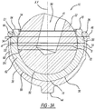
Figure 3A is a cross-sectional view of the acetabular prosthesis cut at 3-3 inFigure 2 ; -
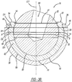
Figure 3B is a cross-sectional view of an alternative acetabular prosthesis; -
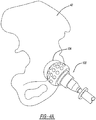
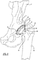
Figures 4A and4B are environmental views illustrating the preparation of an acetabulum according to the present disclosure; -
Figure 5 is an environmental view of an acetabular shell being implanted into the acetabulum ofFigures 4A and4B according to the present disclosure; -
Figure 6 is an environmental view of the acetabulum ofFigures 4A and4B including the acetabular shell according to the present disclosure; -
Figure 7 is an environmental view of the acetabulum ofFigures 4a and4b including the acetabular prosthesis ofFigure 1 ; -
Figure 8 is an environmental view of a femoral head assembled onto a femoral stem and aligned with the acetabulum and acetabular prosthesis ofFigure 7 according to the present disclosure; -
Figure 9 is an environmental view of the femoral head inserted into the acetabular prosthesis in the acetabulum ofFigure 7 according to the present disclosure; and -
Figure 10 is an environmental view of the acetabular prosthesis assembled in the acetabulum according to the present disclosure. - Corresponding reference numerals indicate corresponding parts throughout the several views of the drawings.
- Example embodiments will now be described more fully with reference to the accompanying drawings.
- Example embodiments are provided so that this disclosure will be thorough, and will fully convey the scope to those who are skilled in the art. Numerous specific details are set forth such as examples of specific components, devices, and methods, to provide a thorough understanding of embodiments of the present disclosure. It will be apparent to those skilled in the art that specific details need not be employed, that example embodiments may be embodied in many different forms and that neither should be construed to limit the scope of the disclosure. In some example embodiments, well-known processes, well-known device structures, and well-known technologies are not described in detail. Further, various features in the specific exemplary embodiments may be combined with other specific exemplary embodiments.
- Referring to
Figures 1-3A , an example embodiment of anacetabular prosthesis 10 according to the present disclosure is shown. Theacetabular prosthesis 10 includes a shell orcup 14, a liner orinsert 18, afemoral head 22, and alocking mechanism 26, which may include a ring or clip. Theshell 14 has aninner surface 30 defining acavity 34 and anouter surface 38 capable of being coupled or impacted into an acetabular cup (Figure 6 ) or directly into a prepared acetabulum 42 (Figure 4 ). Theshell 14 may further include abutton 44 to assist in alignment and fixation in the acetabular cup or preparedacetabulum 42. Thebutton 44 may be a projection extending from theouter surface 38 of theshell 14 along an axis X. Thebutton 44 may be of a rectangular or square shape having rounded corners, may be of a circular or semicircular shape, or may be of any other suitable shape for alignment and/or fixation. - Between the
outer surface 38 and theinner surface 30 is a peripheral surface orrim 46. Along theperipheral surface 46, theshell 14 may further include a plurality of notches (not illustrated, but similar to thenotches 96 illustrated inFigures 5 and6 ). The notches may extend along the axis X perpendicular to a plane YZ formed by the peripheral surface orrim 46. The notches may be used to align and/or fix theshell 14 within the preparedacetabulum 42. - The
liner 18 may be disposed within thecavity 34 of theshell 14 at a selected time. Theliner 18 may include aninner surface 50 defining acavity 54 for receiving thehead 22 and anouter surface 58. Theouter surface 58 of theliner 18 may be slideably engaged with theinner surface 30 of theshell 14. Theliner 18 may be formed of a polymer, such as, for example, ultra-high molecular weight polyethylene (UHMWPE). Theliner 18 is constrained within thecavity 34 such that theliner 18 cannot index over when theacetabular prosthesis 10 is assembled intraoperative. In other words, theliner 18 may not move, such as rotate or slide, out of theshell 14 when theliner 18 is assembled into theshell 14. - As discussed further herein, the
liner 18 is configured to move within theshell 14 after positioning theliner 18 within theshell 14. The positionedliner 18 andshell 14, therefore, may be referred to as a dual mobility prosthesis. This may allow a range of motion of a positioned femoral head within the prosthesis greater than if theliner 18 were fixed within theshell 14. Thus, a femur may have a large range of motion. Theliner 18 may be fixed, as discussed further herein, from movement relative to theshell 14 during insertion of the femoral head. In other words, theliner 18 may not move or rotate (i.e. index) such that an axis Y through a rounded edge orrim 64 forming an opening into thecavity 54 of theliner 18 may not move relative to the axis X through anedge 35 forming an opening into thecavity 34 of theshell 14. -
Walls shell 14 andliner 18 may both extend beyond individual hemispheres A and B of theshell 14 andliner 18. This arrangement leads to a dual constraint system and a decreased risk of dislocation of thehead 22 from theacetabular prosthesis 10. Further, the arrangement reduces the need for a constraining feature, increasing the range of motion of thehead 22 in theliner 18. Theliner 18 may extends beyond theperipheral surface 46 of theshell 14. The rounded edge, or rim, 64 extends between theinner surface 50 andouter surface 58. A channel, or groove, 66 extends annularly in theouter surface 58 below the roundededge 64, just beyond theperipheral surface 46 of theshell 14. - Because the
wall 60 of theshell 14 extends beyond the hemisphere A, a diameter D1 of theperipheral surface 46 of theshell 14 is smaller than a diameter D2 of the hemisphere A of theshell 14. Because thewall 62 of theliner 18 extends beyond the hemisphere B, a diameter d1 of the rounded edge or rim 64 is smaller than a diameter d2 of the hemisphere B of theliner 18. Further, theouter surface 58 at the diameter d2 may be larger than the diameter D1, but smaller than diameter D2 such that theliner 18 fits within thecavity 34 of theshell 14. - Since the diameter D2 may be larger than the diameter D1, the
liner 18 cannot be inserted into theshell 14 without deformation. Theliner 18 may be deformed by any known method, such as, for example, by shrinking and expanding theliner 18 into theshell 14. In one example, theliner 18 may be shrunk by cooling, for example only, in liquid nitrogen, and then theliner 18 will expand within theshell 14 as theliner 18 warms to room temperature. Alternatively, the liner may be deformed by applying manual pressure to theinner surface 50 of adome portion 70 of theliner 18 to manually force theliner 18 into theshell 14. - The
locking mechanism 26 is disposed on theperipheral surface 46 and at least partially within thechannel 66 of theliner 18 and locks within thechannel 66 of theliner 18. Thelocking mechanism 26 may be of a ring shape and functions to retain theliner 18 within theshell 14. Specifically, thelocking mechanism 26 prevents theliner 18 from indexing over, folding over, moving outside of, or sliding out of theshell 14 and thus maintains the orientation of theliner 18 within theshell 14 when thehead 22 is inserted into theliner 18. Thelocking mechanism 26 may include afirst end 74 and a second end 78 (Figures 1 and 2 ). It is envisioned that thelocking mechanism 26 can be initially expanded and disposed at least partially in thechannel 66 of theliner 18. Once in thechannel 66, thelocking mechanism 26 can contract back to an original configuration, applying pressure to thechannel 66 to retain thelocking mechanism 26 on thechannel 66. Thelocking mechanism 26 may extend annularly around theliner 18 such that thefirst end 74 and thesecond end 78 are either touching or slightly spaced apart. For example, thefirst end 74 and thesecond end 78 may be spaced a distance less than half of a circumference of therounded edge 64 of theliner 18. - The
locking mechanism 26 may be formed of a biocompatible metal or polymer, such as UHMWPE. While thelocking mechanism 26 is illustrated as a ring, it is envisioned that other locking mechanisms such as screws, snaps, tabs, locking flanges, or other known locking mechanisms may be used to restrain theliner 18 within theshell 14. - The
liner 18 functions to constrain thehead 22 of afemoral prosthesis 82. Theliner 18 constrains thehead 22 by extending beyond the hemisphere B of theliner 18. A diameter DH of thehead 22 is less than the diameter d2 of the hemisphere B such that thehead 22 fits within thecavity 54 defined by theliner 18. The diameter d1 of therounded edge 64 is less than a diameter DH of thehead 22, and therefore, retains the head within thecavity 54. Thelocking mechanism 26 further restrains thehead 22 within theliner 18. Thus, theinner surface 50 of theliner 18 substantially encapsulates thehead 22 of thefemoral prosthesis 82. - Because the
shell 14 and theliner 18 both extend beyond their respective hemispheres A and B, thelocking mechanism 26 may be removed after all parts of theacetabular prosthesis 10 andfemoral prosthesis 82 are implanted (Figure 10 ). Because theshell 14 andliner 18 extend beyond their respective hemispheres A and Band because diameter D1 of theshell 14 is smaller than diameter D2 of hemisphere A and diameter d1 of theliner 18 is smaller than diameter d2 of hemisphere B, theshell 14 andliner 18 retain thehead 22 within theacetabular prosthesis 10. Thus, an additional locking, such as thelocking mechanism 26, is not needed, and as such,locking mechanism 26 may be removed after implantation of both theacetabular prosthesis 10 and thefemoral prosthesis 82. - The
head 22 may be formed of biocompatible metal, ceramic, or combinations thereof. Astem 86 of thefemoral prosthesis 82 may extend into, and be fixed within, abore 90 within the head 22 (Figure 8 ). Thestem 86 may be fixed within thebore 90 by adhesive, material deformation, or any known method. Thehead 22 may be connected to thestem 86, such as via a neck. The head and stem may be any appropriate proximal femoral implant, such as the proximal femoral implant product sold by Biomet, Inc., as the Taperloc® Hip System. - As illustrated in
Figure 3A , theacetabular prosthesis 10 may include the shell orcup 14, the liner or insert 18, thefemoral head 22, and thelocking mechanism 26 and may be inserted into an acetabular cup 92 (illustrated inFigures 5-10 ). Theacetabular cup 92 may be similar to the acetabular cup Freedom™ Constrained Liner System, sold by Biomet, Inc. or any othersuitable acetabular cup 92. Along aperipheral surface 94, theacetabular cup 92 may include a plurality of notches 96 (illustrated inFigures 5 and6 ). The notches may extend along an axis X perpendicular to a plane YZ formed by the peripheral surface orrim 94. The notches may be used to align theacetabular cup 92 within theprepared acetabulum 42, and/or the notches may fix theshell 14 within theacetabular cup 92. - In various embodiments, as illustrated in
Figure 3B , theshell 14 may function as an acetabular cup and may be inserted directly into theprepared acetabulum 42 removing the need for an additional acetabular cup. In this embodiment, theouter surface 38 of theshell 14 may be smooth and may not include thebutton 44 or therim 46 as described in the embodiment ofFigure 3A . The smooth surface of theshell 14 assists in the fixation of theshell 14 to theprepared acetabulum 42. - The
shell 14 may be coupled to the acetabulum 42 by any appropriate known method. Fixation of theshell 14 may include, for example, a plurality of locking projections (not illustrated) for coupling theshell 14 to theprepared acetabulum 42. Theshell 14 may also include a plurality of through bores (not illustrated) to receive bone coupling fasteners or screws (not illustrated) to fix theshell 14 to theprepared acetabulum 42. Further, theshell 14 may be formed of a biocompatible metal, and theouter surface 38 may be treated to facilitate bone ingrowth or fixation to bone cement, such as, for example, by porous coating. Further, the outer surface may include or be formed to include pores, such as a porous metal material including Regenerex® porous titanium construct sold by Biomet, Inc. -
Figures 4A-10 illustrate a method for implanting theacetabular prosthesis 10. After the natural femoral head (not illustrated) has been dislocated from theacetabulum 42, abore forming tool 100 is used to enlarge anacetabular cavity 104 for acceptance of theacetabular prosthesis 10, as illustrated inFigure 4A . It is understood, in various embodiments, that dislocation of the femoral head is not required. InFigure 4B , anacetabular trial gauge 108 may be used to determine the reaming accuracy and to determine the exterior diameter of theacetabular prosthesis 10 to be used. - The
acetabular cup 92 may be inserted into theprepared acetabulum 42 using animpacting tool 112, as illustrated inFigure 5 . Theacetabular cup 92 may be aligned using either a plurality of fixation holes (that will eventually be used to secure theacetabular cup 92 within the acetabular cavity 104) or the plurality ofnotches 96 disposed on theperipheral surface 94. Theacetabular cup 92 may then be impacted into theacetabular cavity 104 and fixed into place. Theacetabular cup 92 may be coupled to the acetabulum 42 by any appropriate known method. Fixation of theacetabular cup 92 may include, for example, a plurality of locking projections (not illustrated) for coupling theacetabular cup 92 to theprepared acetabulum 42. Theacetabular cup 92 may also include a plurality of through bores (not illustrated) to receive bone coupling fasteners or screws (not illustrated) to fix theacetabular cup 92 to theprepared acetabulum 42. Further, theacetabular cup 92 may be of a biocompatible metal, and anouter surface 98 may be treated to facilitate bone ingrowth or fixation to bone cement, such as, for example, by porous coating. Further, theouter surface 98 may include or be formed to include pores, such as a porous metal material including Regenerex® porous titanium construct sold by Biomet, Inc. Referring specifically toFigure 6 , theprepared acetabulum 42 with the implantedacetabular cup 92 is depicted. - The
liner 18 may be inserted into theshell 14 as illustrated inFigure 7 (alsoFigures 1-3A ). As previously stated, theliner 18 may be inserted into theshell 14 by shrinking and expanding theliner 18 into theshell 14 or by applying manual pressure to theinner surface 50 of thedome portion 70 of theliner 18 to manually force theliner 18 into theshell 14. Once theliner 18 is fit within theshell 14 thelocking mechanism 26 is expanded and placed within thechannel 66 in theliner 18. While it is possible to insert theliner 18 into theshell 14 in the operating room before performing the procedure, this timing may make insertion of theliner 18 into the shell14 more difficult than inserting theliner 18 into theshell 14 during manufacturing in a controlled environment. For example only, cooling in liquid nitrogen, as previously described, may be difficult in the operating room, thus other insertion methods must be utilized. - In various embodiments, the
liner 18 may be pre-fit within theshell 14. During the fabrication process, theliner 18 may be assembled in theshell 14, using methods previously discussed thereby eliminating various procedural steps in the operating room. During assembly, once theliner 18 is inserted in theshell 14, thelocking mechanism 26 is expanded and placed within thechannel 66 in theliner 18. The complete assembly may then be inserted into the acetabular cup 92 (Figure 7 ), during the surgical procedure. - As further illustrated in
Figure 7 , theshell 14,liner 18, and lockingmechanism 26 may be inserted into theacetabular cup 92. Thebutton 44 of theshell 14 may be aligned with a cylindrical receiving portion (not illustrated) in theacetabular cup 92. Thebutton 44 may prevent theshell 14 from rotating within theacetabular cup 92 and may maintain the orientation of theshell 14 within theacetabular cup 92. - As illustrated in
Figure 8 , thehead 22 is fixed to thestem 86 of thefemoral prosthesis 82, and thefemoral prosthesis 82 is implanted into afemur 116. Thefemoral prosthesis 82 may be implanted into thefemur 116 by any known method. Thehead 22 is then aligned with theliner 18. - As illustrated in
Figure 9 , thehead 22 is inserted into theliner 18 of theacetabular prosthesis 10. In some embodiments, a cylindrical surface may be machined into or onto thehead 22, so that thehead 22 may be inserted into theliner 18, such as in the Biomet Freedom™ Constrained Liner System, sold by Biomet, Inc. In other embodiments, thehead 22 may be pressed into theliner 18 with the aid of a mechanical press tool. Thehead 22 engages theinner surface 50 of theliner 18 and will articulate within thecavity 54 defined by theinner surface 50 of theliner 18. As thehead 22 is inserted into theliner 18, thelocking mechanism 26 prevents theliner 18 from indexing over, or moving, such as rotating, out of theshell 14. - Once the
head 22 is positioned within theliner 18, thelocking mechanism 26 may be removed, as illustrated inFigure 10 . Thelocking mechanism 26, during insertion of thehead 22, maintains or fixes theliner 18 in at least one degree of freedom relative to theshell 14. In other words, theliner 18 is not able to at least move out of alignment of the liner axis X with the shell axis Y. In removing thelocking mechanism 26, theliner 18 is freely movable within theshell 14, while being constrained within theshell 14 by the relative geometries of theliner 18 and theshell 14, as discussed above. The movement of theliner 18 within theshell 14, however, increases the range of motion of thehead 22 within theshell 14 while maintaining the reduced risk of dislocation of thehead 22 from theshell 14. - The foregoing description of the embodiments has been provided for purposes of illustration and description. It is not intended to be exhaustive or to limit the disclosure. Individual elements or features of a particular embodiment are generally not limited to that particular embodiment, but, where applicable, are interchangeable and can be used in a selected embodiment, even if not specifically shown or described. The same may also be varied in many ways. Such variations are not necessarily to be regarded as a departure from the invention, the scope of which is defined by the appended claims.
Claims (14)
- An acetabular prosthesis (10) comprising:a shell (14) having a shell inner surface (30);a unitary liner (18) disposed within the shell (14); anda locking mechanism (26) securing the liner (18) within the shell (30),wherein the locking mechanism (26) is configured to be removed when the shell (14), liner (18), and a femoral head (22) are implanted, wherein the shell (14) extends beyond a hemisphere (A) of the shell (14), characterised in that the unitary liner (18) extends beyond a hemisphere (B) of the unitary liner (18), such that an outer liner surface (58) of the unitary liner (18) engages the entirety of the shell inner surface (30) beyond the hemisphere (B) of the unitary liner (18).
- The prosthesis of Claim 1, wherein the shell (14) includes a peripheral surface (46) and a diameter (D1) of the peripheral surface (46) is less than a diameter (D2) of the hemisphere (A) of the shell (14).
- The prosthesis of Claim 1 or 2, wherein the liner (18) includes a rounded edge (64) and a diameter (d1) of the rounded edge (64) is less than a diameter (d2) of the hemisphere (B) of the liner (18).
- The prosthesis of Claim 3, wherein the diameter (D1) of the peripheral surface (46) is less than the diameter of the hemisphere of the liner (18).
- The prosthesis of any of Claims 1-4 wherein the shell (14) is formed of a biocompatible metal and the liner (18) is formed of a biocompatible polymer.
- The prosthesis of any of Claims 1-5 wherein the shell (14) includes a bone engagement surface.
- The prosthesis of any of Claims 1-6, further comprising:the femoral head (22) configured to be disposed within the liner (18), wherein the shell (14) includes an inner surface (30) defining a first cavity (34) and the liner (18) includes an inner surface (50) defining a second cavity (54), the liner (18) configured to be disposed within the first cavity (34) and the femoral head (22) configured to be disposed within the second cavity (54).
- The prosthesis of any of Claims 1-7, wherein the liner (18) includes a channel (66) formed in the liner (18) that engages the locking mechanism (26); and
wherein the locking mechanism (26) is configured to engage the shell (14) when engaged in the channel to fix the liner (18) relative to the shell (14) in at least one degree of freedom. - The prosthesis of Claims 1-8, wherein the unitary liner (18) is deformed and expanded when disposed in the shell (14).
- The prosthesis of Claims 1-9, wherein the unitary liner (18) includes a rim (64), wherein a diameter (d1) of the rim (64) is less than a diameter (d2) of the hemisphere (B) of the unitary liner (18).
- The prosthesis of Claims 1-10, wherein the locking mechanism (26) comprises a ring.
- The prosthesis of Claims 1-11, wherein the unitary liner (18) is moveably constrained within the shell (14).
- The prosthesis of Claims 1-7, wherein the unitary liner (18) defines a groove (66) configured to engage the locking mechanism (26).
- The prosthesis of Claim 13, wherein the locking mechanism (26), when engaging the groove (66), fixes the insert (18) in at least one degree of freedom relative to the shell (14).
Applications Claiming Priority (2)
| Application Number | Priority Date | Filing Date | Title |
|---|---|---|---|
| US14/592,367 US9808347B2 (en) | 2015-01-08 | 2015-01-08 | Liner system |
| PCT/US2016/012279 WO2016112070A1 (en) | 2015-01-08 | 2016-01-06 | Liner system |
Publications (2)
| Publication Number | Publication Date |
|---|---|
| EP3242634A1 EP3242634A1 (en) | 2017-11-15 |
| EP3242634B1 true EP3242634B1 (en) | 2018-12-12 |
Family
ID=55168495
Family Applications (1)
| Application Number | Title | Priority Date | Filing Date |
|---|---|---|---|
| EP16700787.1A Active EP3242634B1 (en) | 2015-01-08 | 2016-01-06 | Liner system |
Country Status (3)
| Country | Link |
|---|---|
| US (1) | US9808347B2 (en) |
| EP (1) | EP3242634B1 (en) |
| WO (1) | WO2016112070A1 (en) |
Families Citing this family (4)
| Publication number | Priority date | Publication date | Assignee | Title |
|---|---|---|---|---|
| ES3014215T3 (en) * | 2015-04-17 | 2025-04-21 | Biomet Mfg Llc | Acetabular implant system |
| US12083018B2 (en) | 2020-09-18 | 2024-09-10 | Globus Medical, Inc. | Hip arthroplasty implants |
| US12053383B2 (en) | 2020-09-18 | 2024-08-06 | Globus Medical Inc. | Hip arthroplasty implants |
| CN116196154A (en) * | 2023-03-15 | 2023-06-02 | 大连大学附属中山医院 | Metal shoulder joint prosthesis with porous layer structure and preparation method thereof |
Family Cites Families (6)
| Publication number | Priority date | Publication date | Assignee | Title |
|---|---|---|---|---|
| US3813699A (en) * | 1973-01-15 | 1974-06-04 | R Giliberty | Prosthetic hip joint |
| US3818512A (en) | 1973-05-08 | 1974-06-25 | Y Shersher | Artificial hip-joint with detachable insert |
| US4770658A (en) * | 1987-05-01 | 1988-09-13 | Zimmer, Inc. | Joint prosthesis |
| US5824108A (en) * | 1997-03-26 | 1998-10-20 | Johnson & Johnson Professional, Inc. | Bipolar acetabular cup |
| KR200264044Y1 (en) | 2001-08-21 | 2002-02-19 | 김성곤 | Artificial Hip Joint Prosthesis |
| US20060217815A1 (en) | 2002-09-24 | 2006-09-28 | Biomet Manufacturing Corp | Modular prosthetic head having a flat portion to be implanted into a constrained liner |
-
2015
- 2015-01-08 US US14/592,367 patent/US9808347B2/en active Active
-
2016
- 2016-01-06 EP EP16700787.1A patent/EP3242634B1/en active Active
- 2016-01-06 WO PCT/US2016/012279 patent/WO2016112070A1/en not_active Ceased
Non-Patent Citations (1)
| Title |
|---|
| None * |
Also Published As
| Publication number | Publication date |
|---|---|
| US20160199188A1 (en) | 2016-07-14 |
| US9808347B2 (en) | 2017-11-07 |
| EP3242634A1 (en) | 2017-11-15 |
| WO2016112070A1 (en) | 2016-07-14 |
Similar Documents
| Publication | Publication Date | Title |
|---|---|---|
| US7780739B2 (en) | Method and apparatus for use of a metal-metal constrained liner | |
| EP2381898B1 (en) | Multiple bearing acetabular prosthesis | |
| JP5296667B2 (en) | Acetabular cup assembly for multiple bearing elements | |
| EP1722719B1 (en) | Universal liner assembly for joint replacement | |
| EP2242450B1 (en) | An acetabular cup having an adjustable modular augment | |
| EP2638881B1 (en) | Joint implant trial components | |
| US11931264B2 (en) | Modular humeral head | |
| AU2017346076B2 (en) | Artificial hip joint stem and stem providing method | |
| AU746114B2 (en) | Bipolar acetabular cup | |
| AU2016387348B2 (en) | Constrained dual mobility hip prosthesis | |
| US10322003B2 (en) | Modular taper seal and method for orthopaedic prosthetic hip assembly | |
| EP3946167B1 (en) | Acetabular apparatuses for hip revision surgery | |
| US9808347B2 (en) | Liner system | |
| US12161567B2 (en) | Hard bearing inserter rings | |
| WO2019108242A1 (en) | Acetabular cup assembly | |
| CN110913804A (en) | Elbow prosthesis | |
| EP2663261B1 (en) | A socket, in particular an acetabular socket for a hip endoprosthesis | |
| US12558110B2 (en) | Screw-through acetabular cup system and methods of using the same |
Legal Events
| Date | Code | Title | Description |
|---|---|---|---|
| STAA | Information on the status of an ep patent application or granted ep patent |
Free format text: STATUS: THE INTERNATIONAL PUBLICATION HAS BEEN MADE |
|
| PUAI | Public reference made under article 153(3) epc to a published international application that has entered the european phase |
Free format text: ORIGINAL CODE: 0009012 |
|
| STAA | Information on the status of an ep patent application or granted ep patent |
Free format text: STATUS: REQUEST FOR EXAMINATION WAS MADE |
|
| 17P | Request for examination filed |
Effective date: 20170804 |
|
| AK | Designated contracting states |
Kind code of ref document: A1 Designated state(s): AL AT BE BG CH CY CZ DE DK EE ES FI FR GB GR HR HU IE IS IT LI LT LU LV MC MK MT NL NO PL PT RO RS SE SI SK SM TR |
|
| AX | Request for extension of the european patent |
Extension state: BA ME |
|
| DAV | Request for validation of the european patent (deleted) | ||
| DAX | Request for extension of the european patent (deleted) | ||
| GRAP | Despatch of communication of intention to grant a patent |
Free format text: ORIGINAL CODE: EPIDOSNIGR1 |
|
| STAA | Information on the status of an ep patent application or granted ep patent |
Free format text: STATUS: GRANT OF PATENT IS INTENDED |
|
| INTG | Intention to grant announced |
Effective date: 20180615 |
|
| GRAS | Grant fee paid |
Free format text: ORIGINAL CODE: EPIDOSNIGR3 |
|
| GRAA | (expected) grant |
Free format text: ORIGINAL CODE: 0009210 |
|
| STAA | Information on the status of an ep patent application or granted ep patent |
Free format text: STATUS: THE PATENT HAS BEEN GRANTED |
|
| AK | Designated contracting states |
Kind code of ref document: B1 Designated state(s): AL AT BE BG CH CY CZ DE DK EE ES FI FR GB GR HR HU IE IS IT LI LT LU LV MC MK MT NL NO PL PT RO RS SE SI SK SM TR |
|
| REG | Reference to a national code |
Ref country code: GB Ref legal event code: FG4D |
|
| REG | Reference to a national code |
Ref country code: CH Ref legal event code: EP Ref country code: CH Ref legal event code: NV Representative=s name: MICHELI AND CIE SA, CH |
|
| REG | Reference to a national code |
Ref country code: AT Ref legal event code: REF Ref document number: 1075015 Country of ref document: AT Kind code of ref document: T Effective date: 20181215 |
|
| REG | Reference to a national code |
Ref country code: DE Ref legal event code: R096 Ref document number: 602016008145 Country of ref document: DE |
|
| REG | Reference to a national code |
Ref country code: IE Ref legal event code: FG4D |
|
| REG | Reference to a national code |
Ref country code: NL Ref legal event code: MP Effective date: 20181212 |
|
| REG | Reference to a national code |
Ref country code: LT Ref legal event code: MG4D |
|
| PG25 | Lapsed in a contracting state [announced via postgrant information from national office to epo] |
Ref country code: FI Free format text: LAPSE BECAUSE OF FAILURE TO SUBMIT A TRANSLATION OF THE DESCRIPTION OR TO PAY THE FEE WITHIN THE PRESCRIBED TIME-LIMIT Effective date: 20181212 Ref country code: LV Free format text: LAPSE BECAUSE OF FAILURE TO SUBMIT A TRANSLATION OF THE DESCRIPTION OR TO PAY THE FEE WITHIN THE PRESCRIBED TIME-LIMIT Effective date: 20181212 Ref country code: LT Free format text: LAPSE BECAUSE OF FAILURE TO SUBMIT A TRANSLATION OF THE DESCRIPTION OR TO PAY THE FEE WITHIN THE PRESCRIBED TIME-LIMIT Effective date: 20181212 Ref country code: HR Free format text: LAPSE BECAUSE OF FAILURE TO SUBMIT A TRANSLATION OF THE DESCRIPTION OR TO PAY THE FEE WITHIN THE PRESCRIBED TIME-LIMIT Effective date: 20181212 Ref country code: NO Free format text: LAPSE BECAUSE OF FAILURE TO SUBMIT A TRANSLATION OF THE DESCRIPTION OR TO PAY THE FEE WITHIN THE PRESCRIBED TIME-LIMIT Effective date: 20190312 Ref country code: BG Free format text: LAPSE BECAUSE OF FAILURE TO SUBMIT A TRANSLATION OF THE DESCRIPTION OR TO PAY THE FEE WITHIN THE PRESCRIBED TIME-LIMIT Effective date: 20190312 Ref country code: ES Free format text: LAPSE BECAUSE OF FAILURE TO SUBMIT A TRANSLATION OF THE DESCRIPTION OR TO PAY THE FEE WITHIN THE PRESCRIBED TIME-LIMIT Effective date: 20181212 |
|
| REG | Reference to a national code |
Ref country code: AT Ref legal event code: MK05 Ref document number: 1075015 Country of ref document: AT Kind code of ref document: T Effective date: 20181212 |
|
| PG25 | Lapsed in a contracting state [announced via postgrant information from national office to epo] |
Ref country code: RS Free format text: LAPSE BECAUSE OF FAILURE TO SUBMIT A TRANSLATION OF THE DESCRIPTION OR TO PAY THE FEE WITHIN THE PRESCRIBED TIME-LIMIT Effective date: 20181212 Ref country code: GR Free format text: LAPSE BECAUSE OF FAILURE TO SUBMIT A TRANSLATION OF THE DESCRIPTION OR TO PAY THE FEE WITHIN THE PRESCRIBED TIME-LIMIT Effective date: 20190313 Ref country code: SE Free format text: LAPSE BECAUSE OF FAILURE TO SUBMIT A TRANSLATION OF THE DESCRIPTION OR TO PAY THE FEE WITHIN THE PRESCRIBED TIME-LIMIT Effective date: 20181212 Ref country code: AL Free format text: LAPSE BECAUSE OF FAILURE TO SUBMIT A TRANSLATION OF THE DESCRIPTION OR TO PAY THE FEE WITHIN THE PRESCRIBED TIME-LIMIT Effective date: 20181212 |
|
| PG25 | Lapsed in a contracting state [announced via postgrant information from national office to epo] |
Ref country code: NL Free format text: LAPSE BECAUSE OF FAILURE TO SUBMIT A TRANSLATION OF THE DESCRIPTION OR TO PAY THE FEE WITHIN THE PRESCRIBED TIME-LIMIT Effective date: 20181212 |
|
| PG25 | Lapsed in a contracting state [announced via postgrant information from national office to epo] |
Ref country code: IT Free format text: LAPSE BECAUSE OF FAILURE TO SUBMIT A TRANSLATION OF THE DESCRIPTION OR TO PAY THE FEE WITHIN THE PRESCRIBED TIME-LIMIT Effective date: 20181212 Ref country code: PT Free format text: LAPSE BECAUSE OF FAILURE TO SUBMIT A TRANSLATION OF THE DESCRIPTION OR TO PAY THE FEE WITHIN THE PRESCRIBED TIME-LIMIT Effective date: 20190412 Ref country code: PL Free format text: LAPSE BECAUSE OF FAILURE TO SUBMIT A TRANSLATION OF THE DESCRIPTION OR TO PAY THE FEE WITHIN THE PRESCRIBED TIME-LIMIT Effective date: 20181212 Ref country code: CZ Free format text: LAPSE BECAUSE OF FAILURE TO SUBMIT A TRANSLATION OF THE DESCRIPTION OR TO PAY THE FEE WITHIN THE PRESCRIBED TIME-LIMIT Effective date: 20181212 |
|
| PG25 | Lapsed in a contracting state [announced via postgrant information from national office to epo] |
Ref country code: EE Free format text: LAPSE BECAUSE OF FAILURE TO SUBMIT A TRANSLATION OF THE DESCRIPTION OR TO PAY THE FEE WITHIN THE PRESCRIBED TIME-LIMIT Effective date: 20181212 Ref country code: SM Free format text: LAPSE BECAUSE OF FAILURE TO SUBMIT A TRANSLATION OF THE DESCRIPTION OR TO PAY THE FEE WITHIN THE PRESCRIBED TIME-LIMIT Effective date: 20181212 Ref country code: RO Free format text: LAPSE BECAUSE OF FAILURE TO SUBMIT A TRANSLATION OF THE DESCRIPTION OR TO PAY THE FEE WITHIN THE PRESCRIBED TIME-LIMIT Effective date: 20181212 Ref country code: IS Free format text: LAPSE BECAUSE OF FAILURE TO SUBMIT A TRANSLATION OF THE DESCRIPTION OR TO PAY THE FEE WITHIN THE PRESCRIBED TIME-LIMIT Effective date: 20190412 Ref country code: SK Free format text: LAPSE BECAUSE OF FAILURE TO SUBMIT A TRANSLATION OF THE DESCRIPTION OR TO PAY THE FEE WITHIN THE PRESCRIBED TIME-LIMIT Effective date: 20181212 |
|
| REG | Reference to a national code |
Ref country code: DE Ref legal event code: R097 Ref document number: 602016008145 Country of ref document: DE |
|
| PG25 | Lapsed in a contracting state [announced via postgrant information from national office to epo] |
Ref country code: LU Free format text: LAPSE BECAUSE OF NON-PAYMENT OF DUE FEES Effective date: 20190106 |
|
| REG | Reference to a national code |
Ref country code: BE Ref legal event code: MM Effective date: 20190131 |
|
| PLBE | No opposition filed within time limit |
Free format text: ORIGINAL CODE: 0009261 |
|
| STAA | Information on the status of an ep patent application or granted ep patent |
Free format text: STATUS: NO OPPOSITION FILED WITHIN TIME LIMIT |
|
| REG | Reference to a national code |
Ref country code: IE Ref legal event code: MM4A |
|
| PG25 | Lapsed in a contracting state [announced via postgrant information from national office to epo] |
Ref country code: DK Free format text: LAPSE BECAUSE OF FAILURE TO SUBMIT A TRANSLATION OF THE DESCRIPTION OR TO PAY THE FEE WITHIN THE PRESCRIBED TIME-LIMIT Effective date: 20181212 Ref country code: MC Free format text: LAPSE BECAUSE OF FAILURE TO SUBMIT A TRANSLATION OF THE DESCRIPTION OR TO PAY THE FEE WITHIN THE PRESCRIBED TIME-LIMIT Effective date: 20181212 Ref country code: SI Free format text: LAPSE BECAUSE OF FAILURE TO SUBMIT A TRANSLATION OF THE DESCRIPTION OR TO PAY THE FEE WITHIN THE PRESCRIBED TIME-LIMIT Effective date: 20181212 Ref country code: AT Free format text: LAPSE BECAUSE OF FAILURE TO SUBMIT A TRANSLATION OF THE DESCRIPTION OR TO PAY THE FEE WITHIN THE PRESCRIBED TIME-LIMIT Effective date: 20181212 |
|
| 26N | No opposition filed |
Effective date: 20190913 |
|
| PG25 | Lapsed in a contracting state [announced via postgrant information from national office to epo] |
Ref country code: BE Free format text: LAPSE BECAUSE OF NON-PAYMENT OF DUE FEES Effective date: 20190131 |
|
| PG25 | Lapsed in a contracting state [announced via postgrant information from national office to epo] |
Ref country code: IE Free format text: LAPSE BECAUSE OF NON-PAYMENT OF DUE FEES Effective date: 20190106 |
|
| PG25 | Lapsed in a contracting state [announced via postgrant information from national office to epo] |
Ref country code: FR Free format text: LAPSE BECAUSE OF NON-PAYMENT OF DUE FEES Effective date: 20190212 |
|
| PG25 | Lapsed in a contracting state [announced via postgrant information from national office to epo] |
Ref country code: TR Free format text: LAPSE BECAUSE OF FAILURE TO SUBMIT A TRANSLATION OF THE DESCRIPTION OR TO PAY THE FEE WITHIN THE PRESCRIBED TIME-LIMIT Effective date: 20181212 |
|
| PG25 | Lapsed in a contracting state [announced via postgrant information from national office to epo] |
Ref country code: MT Free format text: LAPSE BECAUSE OF NON-PAYMENT OF DUE FEES Effective date: 20190106 |
|
| REG | Reference to a national code |
Ref country code: DE Ref legal event code: R082 Ref document number: 602016008145 Country of ref document: DE Representative=s name: VENNER SHIPLEY GERMANY LLP, DE Ref country code: DE Ref legal event code: R082 Ref document number: 602016008145 Country of ref document: DE Representative=s name: VENNER SHIPLEY LLP, DE |
|
| PG25 | Lapsed in a contracting state [announced via postgrant information from national office to epo] |
Ref country code: CY Free format text: LAPSE BECAUSE OF FAILURE TO SUBMIT A TRANSLATION OF THE DESCRIPTION OR TO PAY THE FEE WITHIN THE PRESCRIBED TIME-LIMIT Effective date: 20181212 |
|
| PG25 | Lapsed in a contracting state [announced via postgrant information from national office to epo] |
Ref country code: HU Free format text: LAPSE BECAUSE OF FAILURE TO SUBMIT A TRANSLATION OF THE DESCRIPTION OR TO PAY THE FEE WITHIN THE PRESCRIBED TIME-LIMIT; INVALID AB INITIO Effective date: 20160106 |
|
| PG25 | Lapsed in a contracting state [announced via postgrant information from national office to epo] |
Ref country code: MK Free format text: LAPSE BECAUSE OF FAILURE TO SUBMIT A TRANSLATION OF THE DESCRIPTION OR TO PAY THE FEE WITHIN THE PRESCRIBED TIME-LIMIT Effective date: 20181212 |
|
| P01 | Opt-out of the competence of the unified patent court (upc) registered |
Effective date: 20230526 |
|
| PGFP | Annual fee paid to national office [announced via postgrant information from national office to epo] |
Ref country code: GB Payment date: 20251216 Year of fee payment: 11 |
|
| REG | Reference to a national code |
Ref country code: CH Ref legal event code: U11 Free format text: ST27 STATUS EVENT CODE: U-0-0-U10-U11 (AS PROVIDED BY THE NATIONAL OFFICE) Effective date: 20260201 |
|
| PGFP | Annual fee paid to national office [announced via postgrant information from national office to epo] |
Ref country code: DE Payment date: 20251217 Year of fee payment: 11 |
|
| PGFP | Annual fee paid to national office [announced via postgrant information from national office to epo] |
Ref country code: CH Payment date: 20260201 Year of fee payment: 11 |