EP3242066A1 - Tube clamp - Google Patents
Tube clamp Download PDFInfo
- Publication number
- EP3242066A1 EP3242066A1 EP17174562.3A EP17174562A EP3242066A1 EP 3242066 A1 EP3242066 A1 EP 3242066A1 EP 17174562 A EP17174562 A EP 17174562A EP 3242066 A1 EP3242066 A1 EP 3242066A1
- Authority
- EP
- European Patent Office
- Prior art keywords
- clamp
- tube
- members
- lever
- guillotine
- Prior art date
- Legal status (The legal status is an assumption and is not a legal conclusion. Google has not performed a legal analysis and makes no representation as to the accuracy of the status listed.)
- Granted
Links
Images





Classifications
-
- F—MECHANICAL ENGINEERING; LIGHTING; HEATING; WEAPONS; BLASTING
- F16—ENGINEERING ELEMENTS AND UNITS; GENERAL MEASURES FOR PRODUCING AND MAINTAINING EFFECTIVE FUNCTIONING OF MACHINES OR INSTALLATIONS; THERMAL INSULATION IN GENERAL
- F16L—PIPES; JOINTS OR FITTINGS FOR PIPES; SUPPORTS FOR PIPES, CABLES OR PROTECTIVE TUBING; MEANS FOR THERMAL INSULATION IN GENERAL
- F16L55/00—Devices or appurtenances for use in, or in connection with, pipes or pipe systems
- F16L55/10—Means for stopping flow in pipes or hoses
-
- A—HUMAN NECESSITIES
- A61—MEDICAL OR VETERINARY SCIENCE; HYGIENE
- A61M—DEVICES FOR INTRODUCING MEDIA INTO, OR ONTO, THE BODY; DEVICES FOR TRANSDUCING BODY MEDIA OR FOR TAKING MEDIA FROM THE BODY; DEVICES FOR PRODUCING OR ENDING SLEEP OR STUPOR
- A61M25/00—Catheters; Hollow probes
- A61M25/0009—Making of catheters or other medical or surgical tubes
- A61M25/0014—Connecting a tube to a hub
-
- A—HUMAN NECESSITIES
- A61—MEDICAL OR VETERINARY SCIENCE; HYGIENE
- A61M—DEVICES FOR INTRODUCING MEDIA INTO, OR ONTO, THE BODY; DEVICES FOR TRANSDUCING BODY MEDIA OR FOR TAKING MEDIA FROM THE BODY; DEVICES FOR PRODUCING OR ENDING SLEEP OR STUPOR
- A61M39/00—Tubes, tube connectors, tube couplings, valves, access sites or the like, specially adapted for medical use
- A61M39/22—Valves or arrangement of valves
- A61M39/28—Clamping means for squeezing flexible tubes, e.g. roller clamps
- A61M39/284—Lever clamps
-
- A—HUMAN NECESSITIES
- A61—MEDICAL OR VETERINARY SCIENCE; HYGIENE
- A61M—DEVICES FOR INTRODUCING MEDIA INTO, OR ONTO, THE BODY; DEVICES FOR TRANSDUCING BODY MEDIA OR FOR TAKING MEDIA FROM THE BODY; DEVICES FOR PRODUCING OR ENDING SLEEP OR STUPOR
- A61M39/00—Tubes, tube connectors, tube couplings, valves, access sites or the like, specially adapted for medical use
- A61M39/22—Valves or arrangement of valves
- A61M39/28—Clamping means for squeezing flexible tubes, e.g. roller clamps
- A61M39/285—Cam clamps, e.g. roller clamps with eccentric axis
-
- F—MECHANICAL ENGINEERING; LIGHTING; HEATING; WEAPONS; BLASTING
- F16—ENGINEERING ELEMENTS AND UNITS; GENERAL MEASURES FOR PRODUCING AND MAINTAINING EFFECTIVE FUNCTIONING OF MACHINES OR INSTALLATIONS; THERMAL INSULATION IN GENERAL
- F16B—DEVICES FOR FASTENING OR SECURING CONSTRUCTIONAL ELEMENTS OR MACHINE PARTS TOGETHER, e.g. NAILS, BOLTS, CIRCLIPS, CLAMPS, CLIPS OR WEDGES; JOINTS OR JOINTING
- F16B2/00—Friction-grip releasable fastenings
- F16B2/02—Clamps, i.e. with gripping action effected by positive means other than the inherent resistance to deformation of the material of the fastening
- F16B2/06—Clamps, i.e. with gripping action effected by positive means other than the inherent resistance to deformation of the material of the fastening external, i.e. with contracting action
- F16B2/10—Clamps, i.e. with gripping action effected by positive means other than the inherent resistance to deformation of the material of the fastening external, i.e. with contracting action using pivoting jaws
-
- F—MECHANICAL ENGINEERING; LIGHTING; HEATING; WEAPONS; BLASTING
- F16—ENGINEERING ELEMENTS AND UNITS; GENERAL MEASURES FOR PRODUCING AND MAINTAINING EFFECTIVE FUNCTIONING OF MACHINES OR INSTALLATIONS; THERMAL INSULATION IN GENERAL
- F16K—VALVES; TAPS; COCKS; ACTUATING-FLOATS; DEVICES FOR VENTING OR AERATING
- F16K7/00—Diaphragm valves or cut-off apparatus, e.g. with a member deformed, but not moved bodily, to close the passage ; Pinch valves
- F16K7/02—Diaphragm valves or cut-off apparatus, e.g. with a member deformed, but not moved bodily, to close the passage ; Pinch valves with tubular diaphragm
- F16K7/04—Diaphragm valves or cut-off apparatus, e.g. with a member deformed, but not moved bodily, to close the passage ; Pinch valves with tubular diaphragm constrictable by external radial force
- F16K7/06—Diaphragm valves or cut-off apparatus, e.g. with a member deformed, but not moved bodily, to close the passage ; Pinch valves with tubular diaphragm constrictable by external radial force by means of a screw-spindle, cam, or other mechanical means
-
- F—MECHANICAL ENGINEERING; LIGHTING; HEATING; WEAPONS; BLASTING
- F16—ENGINEERING ELEMENTS AND UNITS; GENERAL MEASURES FOR PRODUCING AND MAINTAINING EFFECTIVE FUNCTIONING OF MACHINES OR INSTALLATIONS; THERMAL INSULATION IN GENERAL
- F16K—VALVES; TAPS; COCKS; ACTUATING-FLOATS; DEVICES FOR VENTING OR AERATING
- F16K7/00—Diaphragm valves or cut-off apparatus, e.g. with a member deformed, but not moved bodily, to close the passage ; Pinch valves
- F16K7/02—Diaphragm valves or cut-off apparatus, e.g. with a member deformed, but not moved bodily, to close the passage ; Pinch valves with tubular diaphragm
- F16K7/04—Diaphragm valves or cut-off apparatus, e.g. with a member deformed, but not moved bodily, to close the passage ; Pinch valves with tubular diaphragm constrictable by external radial force
- F16K7/06—Diaphragm valves or cut-off apparatus, e.g. with a member deformed, but not moved bodily, to close the passage ; Pinch valves with tubular diaphragm constrictable by external radial force by means of a screw-spindle, cam, or other mechanical means
- F16K7/063—Lever clamps
-
- F—MECHANICAL ENGINEERING; LIGHTING; HEATING; WEAPONS; BLASTING
- F16—ENGINEERING ELEMENTS AND UNITS; GENERAL MEASURES FOR PRODUCING AND MAINTAINING EFFECTIVE FUNCTIONING OF MACHINES OR INSTALLATIONS; THERMAL INSULATION IN GENERAL
- F16K—VALVES; TAPS; COCKS; ACTUATING-FLOATS; DEVICES FOR VENTING OR AERATING
- F16K7/00—Diaphragm valves or cut-off apparatus, e.g. with a member deformed, but not moved bodily, to close the passage ; Pinch valves
- F16K7/02—Diaphragm valves or cut-off apparatus, e.g. with a member deformed, but not moved bodily, to close the passage ; Pinch valves with tubular diaphragm
- F16K7/04—Diaphragm valves or cut-off apparatus, e.g. with a member deformed, but not moved bodily, to close the passage ; Pinch valves with tubular diaphragm constrictable by external radial force
- F16K7/06—Diaphragm valves or cut-off apparatus, e.g. with a member deformed, but not moved bodily, to close the passage ; Pinch valves with tubular diaphragm constrictable by external radial force by means of a screw-spindle, cam, or other mechanical means
- F16K7/065—Cam clamps
-
- Y—GENERAL TAGGING OF NEW TECHNOLOGICAL DEVELOPMENTS; GENERAL TAGGING OF CROSS-SECTIONAL TECHNOLOGIES SPANNING OVER SEVERAL SECTIONS OF THE IPC; TECHNICAL SUBJECTS COVERED BY FORMER USPC CROSS-REFERENCE ART COLLECTIONS [XRACs] AND DIGESTS
- Y10—TECHNICAL SUBJECTS COVERED BY FORMER USPC
- Y10T—TECHNICAL SUBJECTS COVERED BY FORMER US CLASSIFICATION
- Y10T24/00—Buckles, buttons, clasps, etc.
- Y10T24/44—Clasp, clip, support-clamp, or required component thereof
- Y10T24/44256—Clasp, clip, support-clamp, or required component thereof with specifically shaped, nongripping, rigid structure for connecting independently operable clasps, clips, or support-clamps
-
- Y—GENERAL TAGGING OF NEW TECHNOLOGICAL DEVELOPMENTS; GENERAL TAGGING OF CROSS-SECTIONAL TECHNOLOGIES SPANNING OVER SEVERAL SECTIONS OF THE IPC; TECHNICAL SUBJECTS COVERED BY FORMER USPC CROSS-REFERENCE ART COLLECTIONS [XRACs] AND DIGESTS
- Y10—TECHNICAL SUBJECTS COVERED BY FORMER USPC
- Y10T—TECHNICAL SUBJECTS COVERED BY FORMER US CLASSIFICATION
- Y10T24/00—Buckles, buttons, clasps, etc.
- Y10T24/44—Clasp, clip, support-clamp, or required component thereof
- Y10T24/44966—Clasp, clip, support-clamp, or required component thereof having gripping member shifted by operator
Definitions
- the invention relates to a conduit clamp for closing a pathway defined by a conduit, and more particularly for closing a pathway defined by medical tubing.
- Tubing often made of a flexible material such as plastic or rubber, is widely used in the medical, pharmaceutical, biopharmaceutical, food and beverage and other laboratory environments. While the tubing typically serves as a conduit for fluid, occasionally it is useful to close the tubing, thereby stopping the flow of the fluid through the tube. To this end, various devices have been developed to close tubing. Many such devices include a moveable tube closing member having a portion engaged directly by a hand of a user to move the tube closing member into contact with the tubing and to close the tubing.
- the clamp for compressing a flexible tube.
- the clamp includes a first member and a second member moveably coupled to the first member to move into and out of a clamping position to apply a compressive force to the tube.
- the clamp also includes a locking member to hold the first and second members in the clamping position and a third member moveably retained between a pair of sidewalls of one of the first member and the second member.
- the clamp includes a fourth member moveably coupled to one of the first member and the second member and engageable with the third member to apply an additional compressive force to the tube.
- the clamp in another such embodiment, includes a first member having a first end and a second end and a second member with a first end and a second end.
- the first and second members are moveably coupled at their first ends to move into and out of a clamping position to apply a compressive force to the tube.
- the clamp also includes a locking member pivotally coupled to the second end of at least one of the first member and second member. The locking member is adapted to hold the first and second members in the clamping position.
- the clamp includes a lever member moveably coupled to one of the first member and the second member to apply an additional compressive force to the tube.
- tubing in the medical and pharmaceutical industries has recently become larger. For example, tubing having a 1.5" outer diameter with a 0.25" wall thickness is now commonly used. Such tubing may be difficult to compress an amount sufficient to close the tubing by hand using known devices. Indeed, closing such tubing using known devices can require using a large amount of one's body weight.
- a tube 12 as shown in FIG. 1 can define a fluid pathway 11.
- the tube 12 can be any type of tubing, such as tubing used in the medical or pharmaceutical industries for selectively controlling the flow of fluid.
- the tube 12 can also any other type of flexible tubing tubing such as those used in irrigation or a garden hose.
- the tube 12 can be in communication with a manifold system, a bio-bag, a patient, and/or another object. Additionally, the tube 12 can be resilient such that it automatically re-opens from a closed position when not urged shut. As shown in FIG, 1 , the tube 12 can have an outer diameter of 1.5" and an inner diameter of 1.0", though the tube 12 can have a different outer and/or inner diameter.
- a clamp 10 as shown in FIGS. 2 and 3 can be used for closing the fluid pathway 11 through the tube 12.
- the clamp 10 can include a top member 14 and a bottom member 16 as shown in FIGS. 2 and 3 .
- a first link 18 can be pivotally coupled to a first end 20 of the top member 14 and a first end 22 of the bottom member 16.
- a second link 24 can be pivotally coupled to a second end 26 of the top member 14, and the second link 24 can be selectively engaged with a second end 28 of the bottom member 16.
- the top member 14 When the second link 24 is not engaged with the bottom member 16 as shown in FIG. 2 , the top member 14 can be rotated relative to the bottom member 16. To engage the clamp 10 with the tube 12, the top member 14 can be rotated away from the bottom member 16 such that there is a sufficient distance between the top and bottom members 14 and 16 to insert the tube 12 there between. With the top and bottom members 14 and 16 rotated sufficiently apart from one another, the clamp 10 can be moved to position the tube 12 between the top and bottom members 14 and 16, and then the top member 14 can be rotated toward the bottom member 16 to the position shown in FIGS. 2 and 3 .
- the top member 14 can initially contact the tube 12, at which time the tube 12 is still fully open.
- the top member 14 can be angled obliquely relative to the bottom member 16 (i.e., the top member 14 can be angled away from the bottom member 16 relative to the position of the top member in FIG. 2 ).
- the tube 12 can be initially deformed, thereby narrowing but not fully closing the pathway 11. Due to the geometry and construction of the tube 12, rotation of the top member 14 toward the bottom member 16 to initially deform the tube 12 can require a relatively small amount of force and can be accomplished by hand without a great deal of effort.
- the top member 14 can be rotated by hand without applying one's body weight to a position in which the tube 12 is partially closed as shown in partially closed as shown in FIG. 2 .
- a mechanical advantage can be employed such that the force applied to the tube is a multiple of the force applied by hand to the lever. Therefore, even if a large force is required to close the tubing, the amount of force a user must input to the lever to close the tubing can be low.
- the pathway 11 is narrowed.
- the tube 12 can exert greater and greater amounts of force in opposition to rotation of the top member 14 toward the bottom member 16 as the tube 12 is narrowed, rotation of the top member 14 toward the bottom member 16 can eventually require a sufficiently large amount of force that continued rotation of the top member 14 toward the bottom member 16 by hand becomes difficult even though the tube 12 is not fully closed.
- the amount of force can be especially large when the tube 12 is of the oversized variety (e.g., having the 1.5" outer diameter and 1.0" inner diameter as shown in FIG. 1 ). With the clamp 10, however, the top member 14 need not be rotated until it is sufficiently close to the bottom member 16 to fully close the tube 12.
- top member 14 can be rotated toward the bottom member 16 only until the top member 14 is generally parallel with the bottom member 16 as shown in FIGS. 2 and 3 , as deforming the tube 12 to allow the top and bottom members 14 and 16 to be parallel can still require a small enough amount of force to be performed by hand.
- the second link 24 can be engaged with the bottom member 16 as shown in FIG. 3 to hold the top and bottom members 14 and 16 in the parallel position.
- a guillotine 30 can be actuated to fully close the tube 12 as shown in FIG. 3 .
- the guillotine 30 can be hinged to the top member 14 by a hinge 32 positioned near the second end 26 of the top member 14, and the top member 14 can include another hinge 33 to which a lever 34 having a cam portion 36 is rotatably coupled.
- the lever 34 can be actuated by rotating the lever 34 toward the top member 14, thereby causing the cam portion 36 to engage the guillotine 30 and urge the guillotine 30 downward from the position shown in FIG. 2 to the position shown in FIG, 3 to fully close the tube 12.
- the lever 34 can be rotated away from the top member 14, thereby disengaging the cam portion 36 from the guillotine 30. If resilient, the tube 12 can urge the guillotine 30 upward from the closed state shown in FIG. 3 to the open state shown in FIG. 1 .
- the second link 24 can be disengaged from the bottom member 16, and the top member 14 can be rotated away from the bottom member 16.
- the top member 14 can include a first sidewall 38 and a second sidewall 40.
- the sidewalls 38 and 40 can be generally parallel, and the sidewalls 38 and 40 can be spaced apart to define a channel 42 having a width slightly greater than a width of the guillotine 30.
- the guillotine 30 can move upward and downward between the sidewalls 38 and 40, as can be understood from FIGS. 4 and 5 .
- a first lip 44 can extend from the first sidewall 38 toward the second sidewall 40, while a second slip 46 can extend from the second sidewall 40 toward the first sidewall 38.
- the lips 44 and 46 can be spaced apart by a distance less than the width of the guillotine 30.
- the lips 44 and 46 can limit movement of the guillotine 30 in a direction downward toward the bottom member 16 as shown in FIG. 5 .
- the top member 14 can additionally include four pins 48, with one pin 48 projecting perpendicularly from the first end 20 of the first sidewall 38 in a direction away from the second sidewall 40, a second pin 48 projecting perpendicularly from the second end 26 of the first sidewall 38 in a direction away from the second sidewall 40, a third pin 48 projecting perpendicularly from the first end 20 of the second sidewall 40 in a direction away from the first sidewall 38, and a fourth pin 48 projecting perpendicularly from the second end 26 of the second sidewall 40 in a direction away from the first sidewall 38.
- each of the first and second sidewalls 38 and 40 can include an upwardly extending flange 47 defining an aperture 49. The flanges 47 can be spaced along the length of the top member 14 from the hinge 32, with the distance between the flanges 47 and the hinge 32 affecting the mechanical advantage provided by the lever 34.
- the bottom member 16 can include a first sidewall 50 and a second sidewalls 52 parallel to and spaced apart from the first sidewall 50.
- a platform 54 can extend between the first and second sidewalls 50 and 52, and a V-shaped ridge 56 can extend a length of the platform 54.
- a first foot 58 can run a length of the first sidewall 50, and the first foot 58 can extend away from the second sidewall 52.
- a second foot 60 can run a length of the second sidewall 52, and the second foot 60 can extend away from the first sidewall 50.
- the feet 58 and 60 can provide stability for the clamp 10 when the clamp 10 rests on a desk or other surface.
- the bottom member 16 can additionally include four pins 62, with one pin 62 projecting perpendicularly from the first end 22of the first sidewall 50 in a direction away from the second sidewall 52, another pin 62 projecting perpendicularly from the second end 28 of the first sidewall 50 in a direction away from the second sidewall 52, a third pin 62 projecting perpendicularly from the first end 22 of the second sidewall 52 in a direction away from the first sidewall 50, and a fourth pin 62 projecting perpendicularly from the second end 28 of the second sidewall 52 in a direction away from the first sidewall 50.
- the first link 18 can include a backwall 64 and first and second sidewalls 66 and 68, respectively, extending parallel to one another and generally perpendicular to the backwall 64 from opposing longitudinal edges of the backwall 64.
- Each sidewall 66 and 68 can define two first apertures 70, with the apertures 70 near opposing longitudinal ends of the sidewalls 66 and 68.
- the pins 48 and 62 projecting from the first end 20 of the top member 14 are inserted into the top apertures 70 in the first and second sidewalls 66 and 68, respectively, of the first link 18.
- the pins 48 and 62 projecting from the first end 22 of the bottom member 14 are inserted into the bottom apertures 70 in the first and second sidewalls 66 and 68, respectively.
- the second link 24 can include a backwall 72 and first and second sidewalls 74 and 76, respectively, extending parallel to one another and generally perpendicular to the backwall 72 from opposing longitudinal edges of the backwall 72.
- a tab 82 can extend from a top end of the backwall 78.
- Each sidewall 74 and 76 can define an aperture 78 near the tab 82 and a slot 80 opening to a side of the sidewalls 74 or 76 opposite the backwall 72 near an end of the second link 24 opposite the tab 82.
- the pins 48 and 62 projecting from the second end 26 of the top member 14 are inserted into the apertures 78 of the first and second sidewalls 74 and 76, respectively, of the second link 24.
- the second link 24 is rotated relative to the top member 14 toward the bottom member 16 until the pins 48 and 62 projecting from the second end 28 of the bottom member 16 are disposed in the slots 80 of the second link 24.
- the tube 12, if resilient, will be deformed between the top and bottom members 14 and 16 as shown in FIG. 2 , and the tube 12 can thus exert of force urging the top and bottom members 14 and 16 away from each other.
- the guillotine 30 can have a V-shaped edge 84, which can face the V-shaped rib 56 of the platform 54 of the bottom member 16 as shown in FIG. 5 .
- the V-shaped edge 84 and V-shaped rib 56 can act to create a high pressure location on the tube 12 when the clamp 10 is engaged with the tube 12, thereby reducing the amount of force required to deform the tube 12.
- the guillotine 30 can additionally include a longitudinally extending cross-bar 86 above a lower portion 88 of the guillotine 30 that includes the V-shaped edge 84.
- the width of the lower portion 88 can be less than the distance between the first and second lip 44 and 46 of the top member 14, thereby allowing the lower portion 88 to move below the lips 44 and 46 as shown in FIG. 5 .
- the cross-bar 86 can have a greater width than the distance between the first and second lips 44 and 46 such that the lips 44 and 46 limit the downward movement of the guillotine 30.
- the guillotine 30 can be coupled to the hinge 32 as shown in FIGS. 2 and 3 , which can be a pin passing through both the guillotine 30 and the top member 14. The hinge 32 can limit upward movement of the portion of the guillotine 30 engaged with the hinge 32.
- the lever 34 can include a T-shaped handle 90 and a shank 92 extending toward the hinge 33 as shown in FIG. 16 .
- the proximal end of the shank 92 can include a pair of pins 93 extending through the apertures 49 in the flanges 47 of the top member 14.
- the lever 34 can be coupled to the flanges 47 by forming the lever 34 of a resilient material and snapping the pins 93 into engagement with the flanges 47.
- the shank 92 can have a width less than the distance between the sidewalls 38 and 40 of the top member 14 such that the shank 92 can fit the shank 92 can fit between the sidewalls 38 and 40 when the lever 34 is engaged as shown in FIG. 5 .
- the handle 90 can fit snuggly against the tab 82 of the second link 24 when the lever 34 is engaged as shown in FIG. 3 .
- the cam portion 36 of the lever 34 can extend further from a rotation axis of the lever 34 (i.e., an axis passing axially through the pins 93) than a bottom portion 94 of the lever 34 as shown in FIG. 12 .
- the lever 34 can exert a greater downward force on the guillotine 30 as the lever 34 is rotated as shown in FIGS. 12-14 , and thus rotation of the lever 34 can cause the guillotine 30 to exert a downward force on the tube 12.
- the cam portion 36 can be of sufficient size to urge the guillotine 30 downward as shown in FIG. 14 to fully close the tube 12.
- FIG. 12-14 The clamping sequence performed using the clamp 10 is shown in FIG. 12-14 beginning with the top and bottom members 14 and 16 parallel and partially closing the tube 12 as shown in FIG. 12 and ending with the tube 12 fully closed as shown in FIG. 14 .
- Using the lever 34 to urge the guillotine 30 downward to close the tube 12 provides a mechanical advantage as a result of the distance between the handle 90 of the lever 34 and the pins 93 compared to the distance between the cam portion 36 of the lever 34 and the pins 93 as can be seen in FIG. 14 .
- the clamp 10 provides another mechanical advantage in that there is a relatively long distance between where the cam portion 36 contacts the guillotine 30 and the hinge 33 as shown in FIGS. 13 and 14 . As a result, the force required to fully close the tube 12 can be sufficiently low that the clamp 10 can be operated by hand without much difficulty.
- the clamp 10 can vary from the example described above.
- the clamp 10 instead of forming pins 48 and 62 that are integral with the top and bottom member 14 and 16, respectively, separate pins can be inserted through apertures in the top and bottom members 14 and 16.
- the slots 80 instead of the slots 80 held in engagement with the pins 48 and 62 due to friction between the second link 24 and bottom member 16, the slots 80 can be formed to engage the pins 48 and 62 with a snap-fit.
- a stop or other structure can be used to limit the upward movement of the guillotine 30.
- a different structure can be used to provide a mechanical advantage for closing the tube 12.
- An example of such a different structure is the lever 34 including a ratchet portion at its proximal end, and the guillotine 30 including a vertically oriented rack of gear teeth engaged with the ratchet portion of the lever 34 for vertical movement of the guillotine in response to rotation of the lever 34.
- the clamp 10 can offer many advantages.
- the clamp 10 can be installed on the tube 12 even if the tube 12 is of the oversized variety without requiring an amount of force greater than that which can be applied by hand without significant straining (e.g., without the user having to apply his bodyweight to the clamp 10).
- the clamp 10 can be installed on an intermediate portion of the tube 12 without having to thread the clamp 10 onto an end of the tube 12.
- FIGS. 18 and 19 Another example of clamp 110 is shown in FIGS. 18 and 19 .
- the clamp 110 can include a top member 114 rotatably coupled to a bottom member 116.
- the top and bottom members 114 and 116 can have similar structures as the top and bottom members 14 and 16 with the exception of a few differences.
- One such difference can be that instead of being rotatably coupled by the first link 18, first ends 120 and 122 of the top and bottom members 114 and 116, respectively, can define a hinge 118.
- the first end 120 of the top member 114 can define two spaced apart sidewalls 118a and 118b, and the bottom member 116 can define a pin 118c extending through apertures 118d in the two sidewalls 118a and 118b.
- a second link 124 similar to the second link 24 can be rotatably coupled to a second end 126 of the top member 114 and engagable with a second end 128 of the bottom member 118.
- a lever 134 can be coupled to a hinge 133 that is similar to the hinge 33, and the lever 134 can include a cam portion for actuating a guillotine carried by the top member 114 in a similar fashion as to how the cam portion 36 actuates the guillotine 30 carried by the top member 14.
- the lever 134 can become automatically locked in engagement with another portion of the clamp 110, such as the top member 114 or second link 124, in response to being rotated into an actuated position shown in FIG. 18 in which the cam portion actuates the guillotine.
- a distal end 136 of the lever 134 can define a button 138.
- the button 138 can be rotatable about an axis, e.g., an axis parallel to an axis of rotation of the lever 134 about the hinge 133.
- An example of the button 138 shown in FIG. 20 can be connected to a remaining portion of the lever 134 by two tabs 138a and 138b, and spaces 141 can be defined between the button 138 and the remaining portion of the lever 134.
- a projection 140 can extend from a side of the button 138 facing the bottom member 116 and can include a barb 142 at its distal end opposite the button 138.
- the barb 142 can include an angled surface 142a such that the surface 142a contacts a crossmember 144 extending between two sidewalls of the top member 114 during rotation of the lever 134 into the actuated position.
- the angle of the surface 142a can allow the barb 142 to produce a force urging the projection 140 and/or button 138 to rotate such that the barb 142 is allowed to slide past the crossmember 144.
- the barb 142 can engage a side of the crossmember 144 facing the bottom member 116 as a result of, for example, tubing 12 compressed between the top and bottom members 114 and 116 urging the members 114 and 116 away from one another.
- the top member 114 With the barb 142 engaged with the crossmember 144, the top member 114 is locked in the actuated position.
- the button 138 can be rotatable in the direction indicated by the arrow shown in FIG. 19 as a result of being compressed by, for example, a finger or thumb of an operator. Rotation of the button 138 in the direction indicated in FIG. 19 can move the barb 142 such that it does not engage the crossmember 144, and the force created by compressed tubing 12 between the top and bottom members 114 and 116 can urge the members 114 and 116 away from one another.
- an automatic locking feature is shown as including the button 140 and the projection 140 with its barb 142
- other automatic locking structures can be used.
- one or more projections with barbed distal ends can extend upward from the top member 114 for engagement with a portion of the lever 114 when the lever is moved into the actuated position.
- the lever 134 can include a barbed projection that engages the second link 124 instead of the top member 114.
- the clamp 110 can offer the same advantages as the clamp 10. Additionally, the clamp 110 can allow the top member 114 to be automatically lockable in response to being moved into an actuated position relative to the bottom member 114, and the automatic lock can be selectively disengaged.
- FIGS. 21-29 Another example of a clamp 210 is shown in FIGS. 21-29 , which can offer the same advantages as the clamp 10 and 110.
- FIGS. 21 and 22 illustrate the clamp 210 in an unengaged position
- FIGS. 23-29 illustrate the clamp 210 in an engaged position (without the tube 12).
- the clamp 210 can include a top member 214 rotatably coupled to a bottom member 216.
- the leverage of bottom member 216 can permit the clamp 210 to restrict the fluid flow in, for example, heavy wall tubing similar to that shown in FIG. 1 .
- first ends 220 and 222 of the top and bottom members 214 and 216 can define a hinge 218.
- the first end 220 of the top member 214 can define two spaced apart sidewalls 218a and 218b, and the bottom member 216 can define a pin 218c extending through apertures 218d in the two sidewalls 218a and 218b.
- a link 224 can be rotatably coupled to a second end 226 of the top member 214 and engagable with a second end 228 of the bottom member 218.
- Two stop members 233 extend from the top member 214 that assist in preventing the link 224 from over-travel.
- a lever 234 can be coupled to a hinge 233 that is similar to the hinge 133, and the lever 234 can include a cam portion 236 for actuating a guillotine 230 carried by the top member 214 in a similar fashion as to how the cam portion 36 actuates the guillotine 30 carried by the top member 114.
- Guillotine 230 may also be interchangeable with other guillotine members that can accommodate tubing of, as discussed previously, different inner and outer diameters. Although only one tube is shown in FIG. 21 , clamp 210 can be capable of clamping multiple tubes at one time.
- the lever 234 is automatically locked in engagement with the top member 214 although the lever 234 may be automatically locked in engagement with another portion of the clamp 210 such as second link 224.
- the lever 234 is automatically locked in response to being rotated into an actuated position shown in which the cam portion 236 actuates the guillotine 230.
- the top member 214 can also include safety lockout holes 235 that can be used in conjunction with, for example, a cable tie (not shown) to prevent the lever 234 from being unlocked once it has been rotated into the actuated position. The operator can thread the cable tie through the holes 265 and secure it tightly around the lever 234. Of course, other types of fasteners can be used to prevent the lever from being unlocked, which may or may not make use of the holes 265.
- the clamp 210 can include buttons 238a and 238b (e.g. pushbuttons) at the second end 236 of top member 210.
- buttons 238a and 238b e.g. pushbuttons
- two projections 239 and 240 extending from lever 234 and facing the bottom member 216 can be inserted into a mating hole 260.
- Mating hole 260 is formed by two arms 250a and 250b laterally extending from button 238a and two arms 252a and 252b laterally extending from button 238b.
- the arms 250a and 250b have a sidewall 260a extending therebetween forming a first wall 260a of mating hole 260.
- the arms 252a and 252b have a sidewall 250b extending therebetween forming a second sidewall 260b of mating 260b of mating hole 260. Extending through an inner portion of the arm 252a is a recess (not shown) that is shaped to slidably receive arm 250a. Similarly, extending through an inner portion of the arm 252b is a recess shaped to slidably receive arm 252a.
- the mating of arms 250a and 252a and the mating of arms 250b and 252h form a third sidewall 260c and a fourth sidewall 260d, respectively, of mating hole 260.
- Projections 239 and 240 each include a barb 241 and 242, respectively at the distal end thereof.
- the barbs 241 and 242 each have an angled surface 239a and 240a, respectively.
- the angle of the surfaces 239a and 240a can allow the barbs 241 and 242 to produce a force urging the buttons 238a and 238b to expand away from one another such that the barbs 241 and 242 are allowed to slide past the sidewalls 260a and 260b, respectively.
- the arm 250a and the arm 252a slidably extend outward in opposing directions and at the same time and the arm 250b and the arm 252b slidably extend outward in opposing directions.
- the barb 241 can engage a side of the button 238a facing the bottom member 216.
- the barb 242 can engage a side of the button 238b facing the bottom member 216.
- buttons 238a and 238b can be inwardly and simultaneously pressed, for example, by a finger and a thumb of an operator. Pressing of the buttons 238a and 238b results in a force that causes the arm 250a and the arm 252a to slidably extend toward one another and, at the same time, and causes the arm 250b and the arm 252b to slidably extend toward one another thereby permitting the barbs 241 and 242 to disengage from the sides of buttons 238a and 239b, respectively, facing the bottom member 216.
- the link 224 can then be pulled from the bottom member 216, thereby permitting the tube 12 to be removed.
- the top member 214 when link 224 is not engaged with the bottom member 216, as shown in FIG. 1 , the top member 214 can be rotated relative to the bottom member 216. To engage the clamp 210 with the tube 12, the top member 214 can be rotated away from the bottom member 216 such that there is a sufficient distance between the top and bottom members 214 and 216 to insert the tube 12 therebetween. With the top and bottom members 214 and 216 rotated sufficiently apart from one another, the clamp 210 can be be moved to position the tube 12 between the top and bottom members 214 and 216, and then the top member 214 can be rotated toward the bottom member 216.
- the link 224 can be engaged with the second end 228 of the bottom member 216 to hold the top and bottom members 214 and 216 in a relatively parallel position.
- the bottom member 216 can be engaged to one of two curved hook members 266 and 268.
- Hook member 266 permits clamp 210 to be in a first engaged position ("stop flow position")
- hook member 268 permits clamp 210 to be in a second engaged position ("start flow position”). In both positions, each of the hooks 266 and 268 is engageable with an engagement platform 272 of bottom member 216.
- a spring 269 extends from link 224 that can aide in closing the link back over the hook members 266 268.
- a curved stop member 274 extends from the platform 272 to maintain the clamp 210 in either the first engaged position or the second engaged position.
- the operator can control the amount of fluid flowing through tube 30.
- the lever 234 is rotated toward the top member 214 in the actuate position, the more the guillotine 230 closes on the tube.
- the guillotine 230 closes on the tube, the fluid flow decreases accordingly.
- the lever 234 can be rotated in away from the top member 214. The flow can be metered in both the first engaged position and the second engaged position.
- the locking link 226 includes two telltale windows 276 and 278 to indicate a flow position of the clamp 210. Specifically, when the hook member 266 is engaged with the platform 272, the telltale window 276 provides the operator with a visual indicator that the clamp 210 is in the stop flow position. Similarly, when the hook member 268 is engaged with the platform 272, the telltale window 278 provides the operator with a visual indicator that the clamp 210 is in the start flow position.
Landscapes
- Engineering & Computer Science (AREA)
- Health & Medical Sciences (AREA)
- General Engineering & Computer Science (AREA)
- Heart & Thoracic Surgery (AREA)
- Mechanical Engineering (AREA)
- Life Sciences & Earth Sciences (AREA)
- Animal Behavior & Ethology (AREA)
- Veterinary Medicine (AREA)
- Hematology (AREA)
- Anesthesiology (AREA)
- Pulmonology (AREA)
- General Health & Medical Sciences (AREA)
- Public Health (AREA)
- Biomedical Technology (AREA)
- Biophysics (AREA)
- Quick-Acting Or Multi-Walled Pipe Joints (AREA)
- Infusion, Injection, And Reservoir Apparatuses (AREA)
- Clamps And Clips (AREA)
- Mutual Connection Of Rods And Tubes (AREA)
- Rigid Pipes And Flexible Pipes (AREA)
Abstract
a first member (214, 216) having a first end and a second end;
a second member (216, 214) with a first end and a second end, the first and second members moveably coupled at their first ends to move into and out of a clamping position to apply a compressive force to the tube (12);
a locking member pivotally coupled to the second end of at least one of the first member and second member, the locking member adapted to hold the first and second members in the clamping position; and
a lever member (234) moveably coupled to one of the first member and the second member to apply an additional compressive force to the tube.
Description
- This application claims priority to
U.S. Provisional Patent Application No. 61/159,994, filed March 13,2009 U.S. Provisional Patent Application No. 61/176,712, filed May 8, 2009 U.S. Provisional Patent Application No. 61/265,502, filed December 1, 2009 12/721,922, filed March 11, 2010 - The invention relates to a conduit clamp for closing a pathway defined by a conduit, and more particularly for closing a pathway defined by medical tubing.
- Tubing, often made of a flexible material such as plastic or rubber, is widely used in the medical, pharmaceutical, biopharmaceutical, food and beverage and other laboratory environments. While the tubing typically serves as a conduit for fluid, occasionally it is useful to close the tubing, thereby stopping the flow of the fluid through the tube. To this end, various devices have been developed to close tubing. Many such devices include a moveable tube closing member having a portion engaged directly by a hand of a user to move the tube closing member into contact with the tubing and to close the tubing.
- Embodiments of a clamp for compressing a flexible tube are disclosed herein. In one such embodiment, the clamp includes a first member and a second member moveably coupled to the first member to move into and out of a clamping position to apply a compressive force to the tube. The clamp also includes a locking member to hold the first and second members in the clamping position and a third member moveably retained between a pair of sidewalls of one of the first member and the second member. Additionally, the clamp includes a fourth member moveably coupled to one of the first member and the second member and engageable with the third member to apply an additional compressive force to the tube.
- In another such embodiment, the clamp includes a first member having a first end and a second end and a second member with a first end and a second end. The first and second members are moveably coupled at their first ends to move into and out of a clamping position to apply a compressive force to the tube. The clamp also includes a locking member pivotally coupled to the second end of at least one of the first member and second member. The locking member is adapted to hold the first and second members in the clamping position. Additionally, the clamp includes a lever member moveably coupled to one of the first member and the second member to apply an additional compressive force to the tube.
- These and other embodiments are described in additional detail hereinafter.
- The description herein makes reference to the accompanying drawings wherein like reference numerals refer to like parts throughout the several views, and wherein:
-
Figure 1 is a side elevation view of an example of a tube; -
Figure 2 is a side elevation view of an example of a tube clamp partially closing the tube ofFIG. 1 ; -
Figure 3 is a side elevation view of the clamp ofFIG. 2 fully closing the tube; -
Figure 4 is a cross-section of the clamp taken along line B-B ofFIG. 2 without the tube; -
Figure 5 is a cross-section of the clamp taken along line A-A ofFIG. 3 without the tube; -
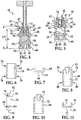
Figure 6 is an end elevation view of a first link of the clamp ofFIG. 2 ; -
Figure 7 is a top plan view of the first link ofFIG. 6 ; -
Figure 8 is an end elevation view of a second link of the clamp ofFIG. 2 ; -
Figure 9 is a side elevation view of the second link ofFIG. 8 ; -
Figure 10 is elevation view of the second link ofFIG. 8 taken from an opposing end of the second link from the view ofFIG. 8 ; -
Figure 11 is a top plan view of the second link ofFIG. 8 ; -
Figure 12 is a side elevation view of the clamp ofFIG. 2 having its second link disengaged from its bottom member and its lever in a released position; -
Figure 13 is a side elevation view of the clamp ofFIG. 12 having its second link engaged with its bottom member and its lever in a partially engaged position; -
Figure 14 is a side elevation view of the clamp ofFIG. 13 having its lever in a fully engaged position; -
Figure 15 is an end elevation view of the clamp ofFIG. 14 ; -
Figure 16 is a top plan view of the clamp ofFIG. 14 ; -
Figure 17 is an end elevation view of a guillotine of the clamp ofFIG. 2 ; -
Figure 18 is a perspective view of another example of a tube clamp; -
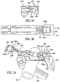
Figure 19 is a partial cross sectional view taken along the line C-C shown inFIG. 18 ; -
Figure 20 is a partial top plan view of a lever of the tube clamp ofFIG. 18 ; and -
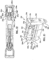
Figure 21 is a perspective view of another example of a tube clamp and a tube in an unengaged position; -
Figure 22 is a top plan view of the clamp ofFIG. 21 without the tube; -
Figure 23 is a perspective view of the clamp ofFIG. 21 in a fully engaged position without the tube; -
Figure 24 is a side elevation view of the clamp ofFIG. 23 ; -
Figure 25 is a top plan view of the clamp ofFIG. 23 ; -
Figure 26 is a cross-section of the clamp taken along line D-D ofFIG. 24 ; -
Figure 27 is a bottom plan view of the clamp ofFIG. 23 ; -
Figure 28 is an end elevation view of the clamp ofFIG. 23 ; and -
Figure 29 is another end elevation view of the clamp ofFIG. 23 . - Tubing in the medical and pharmaceutical industries has recently become larger. For example, tubing having a 1.5" outer diameter with a 0.25" wall thickness is now commonly used. Such tubing may be difficult to compress an amount sufficient to close the tubing by hand using known devices. Indeed, closing such tubing using known devices can require using a large amount of one's body weight.
- A
tube 12 as shown inFIG. 1 can define afluid pathway 11. Thetube 12 can be any type of tubing, such as tubing used in the medical or pharmaceutical industries for selectively controlling the flow of fluid. Thetube 12 can also any other type of flexible tubing tubing such as those used in irrigation or a garden hose. Thetube 12 can be in communication with a manifold system, a bio-bag, a patient, and/or another object. Additionally, thetube 12 can be resilient such that it automatically re-opens from a closed position when not urged shut. As shown inFIG, 1 , thetube 12 can have an outer diameter of 1.5" and an inner diameter of 1.0", though thetube 12 can have a different outer and/or inner diameter. - A
clamp 10 as shown inFIGS. 2 and 3 can be used for closing thefluid pathway 11 through thetube 12. As a general overview of theclamp 10, theclamp 10 can include atop member 14 and abottom member 16 as shown inFIGS. 2 and 3 . Afirst link 18 can be pivotally coupled to afirst end 20 of thetop member 14 and afirst end 22 of thebottom member 16. Asecond link 24 can be pivotally coupled to asecond end 26 of thetop member 14, and thesecond link 24 can be selectively engaged with asecond end 28 of thebottom member 16. - When the
second link 24 is not engaged with thebottom member 16 as shown inFIG. 2 , thetop member 14 can be rotated relative to thebottom member 16. To engage theclamp 10 with thetube 12, thetop member 14 can be rotated away from thebottom member 16 such that there is a sufficient distance between the top andbottom members tube 12 there between. With the top andbottom members clamp 10 can be moved to position thetube 12 between the top andbottom members top member 14 can be rotated toward thebottom member 16 to the position shown inFIGS. 2 and 3 . - During rotation of the
top member 14 toward thebottom member 16, thetop member 14 can initially contact thetube 12, at which time thetube 12 is still fully open. When thetop member 14 initially contacts thetube 12, thetop member 14 can be angled obliquely relative to the bottom member 16 (i.e., thetop member 14 can be angled away from thebottom member 16 relative to the position of the top member inFIG. 2 ). By further rotating thetop member 14 toward thebottom member 16, thetube 12 can be initially deformed, thereby narrowing but not fully closing thepathway 11. Due to the geometry and construction of thetube 12, rotation of thetop member 14 toward thebottom member 16 to initially deform thetube 12 can require a relatively small amount of force and can be accomplished by hand without a great deal of effort. For example, thetop member 14 can be rotated by hand without applying one's body weight to a position in which thetube 12 is partially closed as shown in partially closed as shown inFIG. 2 . As such, a mechanical advantage can be employed such that the force applied to the tube is a multiple of the force applied by hand to the lever. Therefore, even if a large force is required to close the tubing, the amount of force a user must input to the lever to close the tubing can be low. - As the
top member 14 is rotated further toward thebottom member 16 from the position in which thetop member 14 initially contacts thetube 12, thepathway 11 is narrowed. However, since thetube 12 can exert greater and greater amounts of force in opposition to rotation of thetop member 14 toward thebottom member 16 as thetube 12 is narrowed, rotation of thetop member 14 toward thebottom member 16 can eventually require a sufficiently large amount of force that continued rotation of thetop member 14 toward thebottom member 16 by hand becomes difficult even though thetube 12 is not fully closed. The amount of force can be especially large when thetube 12 is of the oversized variety (e.g., having the 1.5" outer diameter and 1.0" inner diameter as shown inFIG. 1 ). With theclamp 10, however, thetop member 14 need not be rotated until it is sufficiently close to thebottom member 16 to fully close thetube 12. - Instead, the
top member 14 can be rotated toward thebottom member 16 only until thetop member 14 is generally parallel with thebottom member 16 as shown inFIGS. 2 and 3 , as deforming thetube 12 to allow the top andbottom members top member 14 andbottom member 16 generally parallel, thesecond link 24 can be engaged with thebottom member 16 as shown inFIG. 3 to hold the top andbottom members - With the top and
bottom members guillotine 30 can be actuated to fully close thetube 12 as shown inFIG. 3 . (Note that the use of the word "guillotine" to describeguillotine 30 does not imply that theguillotine 30 cuts through thetube 12.) Theguillotine 30 can be hinged to thetop member 14 by ahinge 32 positioned near thesecond end 26 of thetop member 14, and thetop member 14 can include anotherhinge 33 to which alever 34 having acam portion 36 is rotatably coupled. Thelever 34 can be actuated by rotating thelever 34 toward thetop member 14, thereby causing thecam portion 36 to engage theguillotine 30 and urge theguillotine 30 downward from the position shown inFIG. 2 to the position shown inFIG, 3 to fully close thetube 12. - To disengage the
clamp 10, thelever 34 can be rotated away from thetop member 14, thereby disengaging thecam portion 36 from theguillotine 30. If resilient, thetube 12 can urge theguillotine 30 upward from the closed state shown inFIG. 3 to the open state shown inFIG. 1 . Thesecond link 24 can be disengaged from thebottom member 16, and thetop member 14 can be rotated away from thebottom member 16. - Now describing the
clamp 10 in detail with reference toFIGS. 4 and 5 , thetop member 14 can include afirst sidewall 38 and asecond sidewall 40. Thesidewalls sidewalls channel 42 having a width slightly greater than a width of theguillotine 30. Thus, theguillotine 30 can move upward and downward between the sidewalls 38 and 40, as can be understood fromFIGS. 4 and 5 . Afirst lip 44 can extend from thefirst sidewall 38 toward thesecond sidewall 40, while asecond slip 46 can extend from thesecond sidewall 40 toward thefirst sidewall 38. Thelips guillotine 30. Thus, thelips guillotine 30 in a direction downward toward thebottom member 16 as shown inFIG. 5 . - The
top member 14 can additionally include fourpins 48, with onepin 48 projecting perpendicularly from thefirst end 20 of thefirst sidewall 38 in a direction away from thesecond sidewall 40, asecond pin 48 projecting perpendicularly from thesecond end 26 of thefirst sidewall 38 in a direction away from thesecond sidewall 40, athird pin 48 projecting perpendicularly from thefirst end 20 of thesecond sidewall 40 in a direction away from thefirst sidewall 38, and afourth pin 48 projecting perpendicularly from thesecond end 26 of thesecond sidewall 40 in a direction away from thefirst sidewall 38. Additionally, each of the first andsecond sidewalls flange 47 defining anaperture 49. Theflanges 47 can be spaced along the length of thetop member 14 from thehinge 32, with the distance between theflanges 47 and thehinge 32 affecting the mechanical advantage provided by thelever 34. - The
bottom member 16 can include afirst sidewall 50 and asecond sidewalls 52 parallel to and spaced apart from thefirst sidewall 50. Aplatform 54 can extend between the first andsecond sidewalls ridge 56 can extend a length of theplatform 54. Afirst foot 58 can run a length of thefirst sidewall 50, and thefirst foot 58 can extend away from thesecond sidewall 52. Asecond foot 60 can run a length of thesecond sidewall 52, and thesecond foot 60 can extend away from thefirst sidewall 50. Thefeet clamp 10 when theclamp 10 rests on a desk or other surface. Thebottom member 16 can additionally include fourpins 62, with onepin 62 projecting perpendicularly from the first end 22of thefirst sidewall 50 in a direction away from thesecond sidewall 52, anotherpin 62 projecting perpendicularly from thesecond end 28 of thefirst sidewall 50 in a direction away from thesecond sidewall 52, athird pin 62 projecting perpendicularly from thefirst end 22 of thesecond sidewall 52 in a direction away from thefirst sidewall 50, and afourth pin 62 projecting perpendicularly from thesecond end 28 of thesecond sidewall 52 in a direction away from thefirst sidewall 50. - As shown in
FIGS. 6 and 7 , thefirst link 18 can include abackwall 64 and first andsecond sidewalls backwall 64. Eachsidewall first apertures 70, with theapertures 70 near opposing longitudinal ends of thesidewalls - To rotatably couple the
first link 18 to thetop member 14, thepins first end 20 of thetop member 14 are inserted into thetop apertures 70 in the first andsecond sidewalls first link 18. Similarly, to rotatably couple thefirst link 18 to thebottom member 16, thepins first end 22 of thebottom member 14 are inserted into thebottom apertures 70 in the first andsecond sidewalls first link 18 from a resilient material and snapping thefirst link 18 onto thetop member 14 andbottom member 16. - As shown in
FIGS. 8-11 , thesecond link 24 can include abackwall 72 and first andsecond sidewalls backwall 72. Atab 82 can extend from a top end of thebackwall 78. Eachsidewall aperture 78 near thetab 82 and aslot 80 opening to a side of the sidewalls 74 or 76 opposite thebackwall 72 near an end of thesecond link 24 opposite thetab 82. - To rotatably couple the
second link 24 to thetop member 14, thepins second end 26 of thetop member 14 are inserted into theapertures 78 of the first andsecond sidewalls second link 24. To engage thesecond link 24 with thebottom member 16 as shown inFIG. 3 , thesecond link 24 is rotated relative to thetop member 14 toward thebottom member 16 until thepins second end 28 of thebottom member 16 are disposed in theslots 80 of thesecond link 24. Thetube 12, if resilient, will be deformed between the top andbottom members FIG. 2 , and thetube 12 can thus exert of force urging the top andbottom members top member 14 is urged away from thebottom member 16 and vice versa, at least one of thepins second end 28 of thebottom member 16 contacts abottom edge 83 of eachslot 80 shown inFIG. 9 , thereby preventing movement of thetop member 14 away from thebottom member 16. The force between thepins second end 28 of thebottom member 16 and thebottom edges 83 of theslots 80 can produce a friction force that aids the engagement between thesecond link 24 andbottom member 16. With thesecond link 24 engaged with thebottom member 16, thetab 82 can extend upward as shown inFIG. 3 . - Referring now to
FIG. 17 , theguillotine 30 can have a V-shapededge 84, which can face the V-shapedrib 56 of theplatform 54 of thebottom member 16 as shown inFIG. 5 . The V-shapededge 84 and V-shapedrib 56 can act to create a high pressure location on thetube 12 when theclamp 10 is engaged with thetube 12, thereby reducing the amount of force required to deform thetube 12. Referring again toFIG. 17 , theguillotine 30 can additionally include a longitudinally extending cross-bar 86 above alower portion 88 of theguillotine 30 that includes the V-shapededge 84. The width of thelower portion 88 can be less than the distance between the first andsecond lip top member 14, thereby allowing thelower portion 88 to move below thelips FIG. 5 . The cross-bar 86, however, can have a greater width than the distance between the first andsecond lips lips guillotine 30. Theguillotine 30 can be coupled to thehinge 32 as shown inFIGS. 2 and 3 , which can be a pin passing through both theguillotine 30 and thetop member 14. Thehinge 32 can limit upward movement of the portion of theguillotine 30 engaged with thehinge 32. - The
lever 34 can include a T-shapedhandle 90 and ashank 92 extending toward thehinge 33 as shown inFIG. 16 . The proximal end of theshank 92 can include a pair ofpins 93 extending through theapertures 49 in theflanges 47 of thetop member 14. Thelever 34 can be coupled to theflanges 47 by forming thelever 34 of a resilient material and snapping thepins 93 into engagement with theflanges 47. Theshank 92 can have a width less than the distance between the sidewalls 38 and 40 of thetop member 14 such that theshank 92 can fit theshank 92 can fit between the sidewalls 38 and 40 when thelever 34 is engaged as shown inFIG. 5 . Additionally, thehandle 90 can fit snuggly against thetab 82 of thesecond link 24 when thelever 34 is engaged as shown inFIG. 3 . Thecam portion 36 of thelever 34 can extend further from a rotation axis of the lever 34 (i.e., an axis passing axially through the pins 93) than abottom portion 94 of thelever 34 as shown inFIG. 12 . Thus, thelever 34 can exert a greater downward force on theguillotine 30 as thelever 34 is rotated as shown inFIGS. 12-14 , and thus rotation of thelever 34 can cause theguillotine 30 to exert a downward force on thetube 12. Thecam portion 36 can be of sufficient size to urge theguillotine 30 downward as shown inFIG. 14 to fully close thetube 12. - The clamping sequence performed using the
clamp 10 is shown inFIG. 12-14 beginning with the top andbottom members tube 12 as shown inFIG. 12 and ending with thetube 12 fully closed as shown inFIG. 14 . Using thelever 34 to urge theguillotine 30 downward to close thetube 12 provides a mechanical advantage as a result of the distance between thehandle 90 of thelever 34 and thepins 93 compared to the distance between thecam portion 36 of thelever 34 and thepins 93 as can be seen inFIG. 14 . Theclamp 10 provides another mechanical advantage in that there is a relatively long distance between where thecam portion 36 contacts theguillotine 30 and thehinge 33 as shown inFIGS. 13 and 14 . As a result, the force required to fully close thetube 12 can be sufficiently low that theclamp 10 can be operated by hand without much difficulty. - Alternatively, the
clamp 10 can vary from the example described above. For example, instead of formingpins bottom member bottom members slots 80 held in engagement with thepins second link 24 andbottom member 16, theslots 80 can be formed to engage thepins hinge 32 that prevents movement of theguillotine 30 in an upward direction as shown inFIGS. 13 and 14 , a stop or other structure can be used to limit the upward movement of theguillotine 30. As still yet another example, a different structure can be used to provide a mechanical advantage for closing thetube 12. An example of such a different structure is thelever 34 including a ratchet portion at its proximal end, and theguillotine 30 including a vertically oriented rack of gear teeth engaged with the ratchet portion of thelever 34 for vertical movement of the guillotine in response to rotation of thelever 34. - The
clamp 10 can offer many advantages. As an example of an advantage of theclamp 10, theclamp 10 can be installed on thetube 12 even if thetube 12 is of the oversized variety without requiring an amount of force greater than that which can be applied by hand without significant straining (e.g., without the user having to apply his bodyweight to the clamp 10). As another example of an advantage of theclamp 10, theclamp 10 can be installed on an intermediate portion of thetube 12 without having to thread theclamp 10 onto an end of thetube 12. - Another example of
clamp 110 is shown inFIGS. 18 and19 . Referring first toFIG. 18 , theclamp 110 can include atop member 114 rotatably coupled to abottom member 116. The top andbottom members bottom members first link 18, first ends 120 and 122 of the top andbottom members first end 120 of thetop member 114 can define two spaced apart sidewalls 118a and 118b, and thebottom member 116 can define apin 118c extending throughapertures 118d in the twosidewalls second link 124 similar to thesecond link 24 can be rotatably coupled to asecond end 126 of thetop member 114 and engagable with asecond end 128 of the bottom member 118. Alever 134 can be coupled to ahinge 133 that is similar to thehinge 33, and thelever 134 can include a cam portion for actuating a guillotine carried by thetop member 114 in a similar fashion as to how thecam portion 36 actuates theguillotine 30 carried by thetop member 14. - Another difference between the
clamps lever 134 can become automatically locked in engagement with another portion of theclamp 110, such as thetop member 114 orsecond link 124, in response to being rotated into an actuated position shown inFIG. 18 in which the cam portion actuates the guillotine. For example, as shown inFIGS. 18-20 , adistal end 136 of thelever 134 can define abutton 138. Thebutton 138 can be rotatable about an axis, e.g., an axis parallel to an axis of rotation of thelever 134 about thehinge 133. An example of thebutton 138 shown inFIG. 20 can be connected to a remaining portion of thelever 134 by twotabs spaces 141 can be defined between thebutton 138 and the remaining portion of thelever 134. - Referring to
FIG. 19 , aprojection 140 can extend from a side of thebutton 138 facing thebottom member 116 and can include abarb 142 at its distal end opposite thebutton 138. Thebarb 142 can include anangled surface 142a such that thesurface 142a contacts acrossmember 144 extending between two sidewalls of thetop member 114 during rotation of thelever 134 into the actuated position. The angle of thesurface 142a can allow thebarb 142 to produce a force urging theprojection 140 and/orbutton 138 to rotate such that thebarb 142 is allowed to slide past thecrossmember 144. Once thebarb 142 slides past thecrossmember 142, thebarb 142 can engage a side of thecrossmember 144 facing thebottom member 116 as a result of, for example,tubing 12 compressed between the top andbottom members members barb 142 engaged with thecrossmember 144, thetop member 114 is locked in the actuated position. To release thetop member 114 from the actuated position, thebutton 138 can be rotatable in the direction indicated by the arrow shown inFIG. 19 as a result of being compressed by, for example, a finger or thumb of an operator. Rotation of thebutton 138 in the direction indicated inFIG. 19 can move thebarb 142 such that it does not engage thecrossmember 144, and the force created bycompressed tubing 12 between the top andbottom members members - While an automatic locking feature is shown as including the
button 140 and theprojection 140 with itsbarb 142, other automatic locking structures can be used. For example, one or more projections with barbed distal ends can extend upward from thetop member 114 for engagement with a portion of thelever 114 when the lever is moved into the actuated position. As another example, thelever 134 can include a barbed projection that engages thesecond link 124 instead of thetop member 114. - The
clamp 110 can offer the same advantages as theclamp 10. Additionally, theclamp 110 can allow thetop member 114 to be automatically lockable in response to being moved into an actuated position relative to thebottom member 114, and the automatic lock can be selectively disengaged. - Another example of a
clamp 210 is shown inFIGS. 21-29 , which can offer the same advantages as theclamp FIGS. 21 and22 illustrate theclamp 210 in an unengaged position andFIGS. 23-29 illustrate theclamp 210 in an engaged position (without the tube 12). Theclamp 210 can include atop member 214 rotatably coupled to abottom member 216. The leverage ofbottom member 216 can permit theclamp 210 to restrict the fluid flow in, for example, heavy wall tubing similar to that shown inFIG. 1 . Similar to the coupling of top andbottom members bottom members hinge 218. For example, thefirst end 220 of thetop member 214 can define two spaced apart sidewalls 218a and 218b, and thebottom member 216 can define apin 218c extending throughapertures 218d in the twosidewalls - A
link 224 can be rotatably coupled to asecond end 226 of thetop member 214 and engagable with asecond end 228 of thebottom member 218. Twostop members 233 extend from thetop member 214 that assist in preventing thelink 224 from over-travel. Alever 234 can be coupled to ahinge 233 that is similar to thehinge 133, and thelever 234 can include acam portion 236 for actuating aguillotine 230 carried by thetop member 214 in a similar fashion as to how thecam portion 36 actuates theguillotine 30 carried by thetop member 114.Guillotine 230 may also be interchangeable with other guillotine members that can accommodate tubing of, as discussed previously, different inner and outer diameters. Although only one tube is shown inFIG. 21 ,clamp 210 can be capable of clamping multiple tubes at one time. - As shown in
Figs. 23-29 , thelever 234 is automatically locked in engagement with thetop member 214 although thelever 234 may be automatically locked in engagement with another portion of theclamp 210 such assecond link 224. Thelever 234 is automatically locked in response to being rotated into an actuated position shown in which thecam portion 236 actuates theguillotine 230. Thetop member 214 can also include safety lockout holes 235 that can be used in conjunction with, for example, a cable tie (not shown) to prevent thelever 234 from being unlocked once it has been rotated into the actuated position. The operator can thread the cable tie through the holes 265 and secure it tightly around thelever 234. Of course, other types of fasteners can be used to prevent the lever from being unlocked, which may or may not make use of the holes 265. - Unlike previous embodiments, the
clamp 210, as shown inFIGS. 21-27 , can includebuttons second end 236 oftop member 210. Upon rotation into the engaged position, twoprojections lever 234 and facing thebottom member 216 can be inserted into amating hole 260.Mating hole 260 is formed by twoarms button 238a and twoarms button 238b. Thearms sidewall 260a extending therebetween forming afirst wall 260a ofmating hole 260. Thearms sidewall 250b extending therebetween forming asecond sidewall 260b ofmating 260b ofmating hole 260. Extending through an inner portion of thearm 252a is a recess (not shown) that is shaped to slidably receivearm 250a. Similarly, extending through an inner portion of thearm 252b is a recess shaped to slidably receivearm 252a. The mating ofarms arms 250b and 252h form athird sidewall 260c and afourth sidewall 260d, respectively, ofmating hole 260. -
Projections barb barbs barbs buttons barbs arm 250a and thearm 252a slidably extend outward in opposing directions and at the same time and thearm 250b and thearm 252b slidably extend outward in opposing directions. Once thebarb 241 slides past thesidewall 260a, thebarb 241 can engage a side of thebutton 238a facing thebottom member 216. Similarly, once thebarb 242 slides past thesidewall 260b, thebarb 242 can engage a side of thebutton 238b facing thebottom member 216. With thebarbs mating hole 260, thetop member 214 is locked in the engaged position. Once theclamp 210 is in the engaged position, the clamp, for example, will not open, unless thelever 234 is unlocked. - To release the
top member 114 from the engaged position, thebuttons buttons arm 250a and thearm 252a to slidably extend toward one another and, at the same time, and causes thearm 250b and thearm 252b to slidably extend toward one another thereby permitting thebarbs buttons 238a and 239b, respectively, facing thebottom member 216. Thelink 224 can then be pulled from thebottom member 216, thereby permitting thetube 12 to be removed. - Similar to the previous embodiments, when link 224 is not engaged with the
bottom member 216, as shown inFIG. 1 , thetop member 214 can be rotated relative to thebottom member 216. To engage theclamp 210 with thetube 12, thetop member 214 can be rotated away from thebottom member 216 such that there is a sufficient distance between the top andbottom members tube 12 therebetween. With the top andbottom members clamp 210 can be be moved to position thetube 12 between the top andbottom members top member 214 can be rotated toward thebottom member 216. - The
link 224 can be engaged with thesecond end 228 of thebottom member 216 to hold the top andbottom members bottom member 216 can be engaged to one of twocurved hook members Hook member 266 permits clamp 210 to be in a first engaged position ("stop flow position"),hook member 268 permits clamp 210 to be in a second engaged position ("start flow position"). In both positions, each of thehooks engagement platform 272 ofbottom member 216. Aspring 269 extends fromlink 224 that can aide in closing the link back over thehook members 266 268. Acurved stop member 274 extends from theplatform 272 to maintain theclamp 210 in either the first engaged position or the second engaged position. Using thelever 234, the operator can control the amount of fluid flowing throughtube 30. In general, the more thelever 234 is rotated toward thetop member 214 in the actuate position, the more theguillotine 230 closes on the tube. As theguillotine 230 closes on the tube, the fluid flow decreases accordingly. Conversely, if the operator desires to increase the fluid flow, thelever 234 can be rotated in away from thetop member 214. The flow can be metered in both the first engaged position and the second engaged position. - The
locking link 226 includes twotelltale windows 276 and 278 to indicate a flow position of theclamp 210. Specifically, when thehook member 266 is engaged with theplatform 272, thetelltale window 276 provides the operator with a visual indicator that theclamp 210 is in the stop flow position. Similarly, when thehook member 268 is engaged with theplatform 272, the telltale window 278 provides the operator with a visual indicator that theclamp 210 is in the start flow position. - While examples of clamps have been described in connection with what are presently considered to be the most practical examples, it is to be understood that the invention is not to be limited to the disclosed examples but, on the contrary, is intended to cover various modifications and equivalent arrangements included within the scope of the appended claims, which scope is to be accorded the broadest interpretation so as to encompass all such modifications and equivalent structures as is permitted under the law.
The following items form part of the description: - 1. A clamp for compressing a flexible tube, comprising: a first member; a second member moveably coupled to the first member to move into and out of a clamping position to apply a compressive force to the tube; a locking member to hold the first and second members in the clamping position; a third member moveably retained between a pair of sidewalls of one of the first member and the second member; and a fourth member moveably coupled to one of the first member and the second member and engageable with the third member to apply an additional compressive force to the tube.
- 2. The clamp of item 1, wherein the first member and the second member each have a first end and an opposing second end, wherein the locking member is rotatably coupled to one of the second end of the top member and the second of the bottom member, and wherein the locking member is engagable with the other one of the second end of the top member and the second of the bottom member.
- 3. The clamp of items 1 or 2, wherein the top member and bottom member are connected at their first ends by one of a connecting member and a hinge.
- 4. The clamp of items 1 or 2, wherein the pair of sidewalls define a channel for upward and downward movement of the third member.
- 5. The clamp of item 4, wherein a lip inwardly extends from at least one of the pair of sidewalls, the lip adapted to limit the downward movement of the third member.
- 6. The clamp of item 4, wherein the third member is moveably coupled to one of the first and second members by a hinge, the hinge adapted to limit the upward movement of the third member.
- 7. The clamp of items 1 or 2, wherein the third member includes a longitudinally extending cross-bar portion and a lower portion, the lower portion having a v- shaped edge extending substantially the entire length thereof.
- 8. The clamp of items 1 or 2, wherein a platform extends substantially the entire length between the pair of sidewalls of the second member, the second member including a ridge extending substantially the entire length of the platform.
- 9. The clamp of items 1 or 2, wherein the fourth member is adapted to lock with one of the first and second members.
- 10. The clamp of items 1 or 2, wherein the fourth member includes a rotatable button and at least one projection extending from a bottom surface of the button, the at least one projection having a barbed end adapted to engage a crossmember when the fourth member is rotated into the clamping position.
- 11. The clamp of items 1 or 2, wherein the fourth member includes at least one projection extending from a bottom surface of the fourth member and one of the first and second members includes first and second pushbuttons extending from opposites sides therefrom, the first and second pushbuttons each having a pair of arms adapted to form a hole, the at least one projection having a barbed end adapted to engage a portion of the hole when the fourth member is rotated into the clamping position.
- 12. The clamp of items 1 or 2, wherein the locking member includes at least one hook member, the hook member adapted to engage with one of the First and second members.
- 13. The clamp of item 1, wherein the locking member includes at least one telltale window, the telltale window adapted to indicate a flow position of the clamp.
- 14. A clamp for compressing a flexible tube, comprising: a first member having a first end and a second end; a second member with a first end and a second end, the first and second members moveably coupled at their first ends to move into and out of a clamping position to apply a compressive force to the tube; a locking member pivotally coupled to the second end of at least one of the first member and second member, the locking member adapted to hold the first and second members in the clamping position; and a lever member moveably coupled to one of the first member and the second member to apply an additional compressive force to the tube.
- 15. The clamp of
item 14, further comprising: a guillotine moveably retained between a pair of sidewalls of one of the first member and the second member. - 16. The clamp of item 15, wherein the lever member is engageable with the guillotine.
- 17. The clamp of
item 16, wherein the guillotine is adapted to apply the additional compressive force to the tube in response to when the lever member engages the guillotine. - 18. A method for compressing at least one flexible tube with a clamp having first and second members, the second member moveably coupled to the first member, a locking member, a third member moveably retained between a pair of sidewalls of one of the first member and the second member and a fourth member moveably coupled to one of the first member and the second member, the method comprising: positioning the at least one tube between the first and second members; rotating the first member toward the second member to a clamping position such that an initial compressive force is applied to the at least one tube; engaging the locking member such that the first and second members are held in the clamping position; and rotating the fourth member to engage the third member such that an additional compressive force is applied to the at least one tube.
- 19. The method of
item 18, wherein the fourth member includes at least one projection extending from a bottom surface of the fourth member and one of the first and second members includes first and second pushbuttons extending from opposites sides therefrom, the first and second pushbuttons each having a pair of arms adapted to form a hole, the at least one projection having a barbed end and wherein rotating the lever to the clamping position includes: engaging the barbed end with a portion of the hole to secure the fourth member. - 20. The method of item 19, further comprising: simultaneously pressing the first and second pushbuttons to disengage the barbed end from the hole to release the fourth member.
- 21. The method of
item 18, wherein the fourth member includes a rotatable button and at least one projection extending from a bottom surface of the button, the at least one projection having a barbed end and wherein one of the first and second members includes a crossmember and wherein rotating the fourth member to the clamping position includes:- engaging the barbed end of the at least one projection with the crossmember to secure the fourth member.
- 22. The method of item 23, further comprising: pressing the button to disengage the barbed end from the cross member to release the fourth member.
- 23. The method of any of
items 18 to 20, further comprising: rotating the fourth member to control the flow of fluid through the at least one tube. - 24. The method of any of
items 18 to 20, wherein the locking member is rotatably coupled to one of the first and second members and includes at least two hook members, wherein engaging the locking link comprises at least one of: engaging a first one of the at least two hook members with the other of the first and second members such that the at least one tube is in a stop flow position; and engaging a second one of the at least two hook members with the other of the first and second members so that the at least one tube is in a start flow position. - 25. The method of any of
items 18 to 20, further comprising: interchanging the third member with a different member. - 26. The method of any of
items 18 to 20, wherein the at least one tube includes a plurality of tubes, the method further comprising: positioning the plurality of tubes between the first and second members ; rotating the first member toward the second member to the clamping position such that the initial compressive force is applied to the plurality of tubes; engaging the locking member such that the first and second members are held in the clamping position; rotating the fourth member to engage the third member such that the additional compressive force is applied to the plurality of tubes.
Claims (15)
- A clamp for compressing a flexible tube, comprising:a first member having a first end and a second end;a second member with a first end and a second end, the first and second members moveably coupled at their first ends to move into and out of a clamping position to apply a compressive force to the tube;a locking member pivotally coupled to the second end of at least one of the first member and second member, the locking member adapted to hold the first and second members in the clamping position; anda lever member moveably coupled to one of the first member and the second member to apply an additional compressive force to the tube.
- The clamp of claim 1, further comprising:a guillotine moveably retained between a pair of sidewalls of one of the first member and the second member.
- The clamp of claim 2, wherein the lever member is engageable with the guillotine.
- The clamp of claim 3, wherein the guillotine is adapted to apply the additional compressive force to the tube in response to when the lever member engages the guillotine.
- The clamp of claim 1, wherein the first member and the second member each have a first end and an opposing second end, and wherein the locking member is engagable with the other one of the second end of the top member and the second of the bottom member.
- The clamp of claim 1, wherein the top member and bottom member are connected at their first ends by one of a connecting member and a hinge.
- The clamp of claim 1, wherein the clamp further comprises a third member movably retained between a pair of sidewalls of one of the first member and the second member.
- The clamp of claim 7, wherein the pair of sidewalls of one of the first member and the second member define a channel for upward and downward movement of the third member.
- The clamp of claim 7, wherein a lip inwardly extends from at least one of the pair of sidewalls, the lip adapted to limit the downward movement of the third member.
- The clamp of claim 7, wherein the third member is moveably coupled to one of the first and second members by a hinge, the hinge adapted to limit the upward movement of the third member.
- The clamp of claim 7, wherein the third member includes a longitudinally extending cross-bar portion and a lower portion, the lower portion having a v-shaped edge extending substantially the entire length thereof.
- The clamp of claim 7, wherein a platform extends substantially the entire length between the pair of sidewalls of the second member, the second member including a ridge extending substantially the entire length of the platform.
- The clamp of claim 7, wherein the clamp further comprises a fourth member moveably coupled to one of the first member and the second member and engageable with the third member to apply an additional compressive force to the tube, wherein the fourth member is adapted to lock with one of the first and second members.
- The clamp of claim 1, wherein the locking member includes at least one hook member, the hook member adapted to engage with one of the first and second members.
- The clamp of claim 1, wherein the locking member includes at least one telltale window, the telltale window adapted to indicate a flow position of the clamp.
Applications Claiming Priority (6)
| Application Number | Priority Date | Filing Date | Title |
|---|---|---|---|
| US15999409P | 2009-03-13 | 2009-03-13 | |
| US17671209P | 2009-05-08 | 2009-05-08 | |
| US26550209P | 2009-12-01 | 2009-12-01 | |
| US12/721,922 US8973889B2 (en) | 2009-03-13 | 2010-03-11 | Tube clamp |
| EP10751459.8A EP2406531B1 (en) | 2009-03-13 | 2010-03-12 | Tube clamp |
| PCT/US2010/027077 WO2010105121A2 (en) | 2009-03-13 | 2010-03-12 | Tube clamp |
Related Parent Applications (1)
| Application Number | Title | Priority Date | Filing Date |
|---|---|---|---|
| EP10751459.8A Division EP2406531B1 (en) | 2009-03-13 | 2010-03-12 | Tube clamp |
Publications (2)
| Publication Number | Publication Date |
|---|---|
| EP3242066A1 true EP3242066A1 (en) | 2017-11-08 |
| EP3242066B1 EP3242066B1 (en) | 2019-06-19 |
Family
ID=42729124
Family Applications (2)
| Application Number | Title | Priority Date | Filing Date |
|---|---|---|---|
| EP17174562.3A Active EP3242066B1 (en) | 2009-03-13 | 2010-03-12 | Tube clamp |
| EP10751459.8A Active EP2406531B1 (en) | 2009-03-13 | 2010-03-12 | Tube clamp |
Family Applications After (1)
| Application Number | Title | Priority Date | Filing Date |
|---|---|---|---|
| EP10751459.8A Active EP2406531B1 (en) | 2009-03-13 | 2010-03-12 | Tube clamp |
Country Status (8)
| Country | Link |
|---|---|
| US (1) | US8973889B2 (en) |
| EP (2) | EP3242066B1 (en) |
| JP (1) | JP5696055B2 (en) |
| KR (1) | KR20110135965A (en) |
| CN (1) | CN102348922B (en) |
| CA (1) | CA2755114A1 (en) |
| MX (1) | MX2011009580A (en) |
| WO (1) | WO2010105121A2 (en) |
Families Citing this family (20)
| Publication number | Priority date | Publication date | Assignee | Title |
|---|---|---|---|---|
| WO2006063245A2 (en) * | 2004-12-08 | 2006-06-15 | Vision-Sciences, Inc. | Endoscope valve |
| US9010597B2 (en) * | 2011-07-15 | 2015-04-21 | Bby Solutions, Inc. | Headrest mount for tablet computer and method |
| US8894035B2 (en) * | 2012-11-02 | 2014-11-25 | Oxo Fab. Inc. | Pinch valve having pivotably mounted upper and lower casings |
| CN103967884B (en) * | 2013-03-28 | 2016-04-20 | 常州华达科捷光电仪器有限公司 | Locking device and there is the laser alignment instrument of this locking device |
| DE102013014217A1 (en) * | 2013-08-26 | 2015-02-26 | Thomas Magnete Gmbh | Hose clamp for holding and closing a hose |
| GB2540176A (en) * | 2015-07-08 | 2017-01-11 | Li Jianhe | Dry powder inhaler apparatus |
| TWI610636B (en) * | 2015-08-21 | 2018-01-11 | Zhong wen liang | Carry-on device |
| KR102257238B1 (en) | 2016-06-27 | 2021-05-28 | 다케다 야쿠힌 고교 가부시키가이샤 | Syringe stabilizer |
| DE102017116105A1 (en) * | 2017-07-18 | 2019-01-24 | B. Braun Melsungen Ag | Device for opening and closing a hose clamp within a pump housing |
| TWI660797B (en) * | 2017-12-19 | 2019-06-01 | 邱宗堯 | Anti-dropping structure of pipe clamp mold of pipe expander |
| CN108466281B (en) * | 2018-06-19 | 2024-01-05 | 苏州大学 | Detachable pneumatic flexible single finger |
| JP7239426B2 (en) * | 2019-08-21 | 2023-03-14 | 株式会社コスモ計器 | Flow resistor, flow control device, flow control method |
| US11707616B2 (en) | 2019-10-09 | 2023-07-25 | Carefusion 303, Inc. | Flow stop device |
| US20210348705A1 (en) * | 2020-05-07 | 2021-11-11 | Garrett N. FRINK | Hose retention apparatus |
| JP7510821B2 (en) * | 2020-08-31 | 2024-07-04 | テルモ株式会社 | Flow Regulator |
| CN113599670B (en) * | 2021-10-08 | 2021-12-03 | 江苏康亦徳医疗器械有限公司 | Portable medical pipe clamp |
| WO2024128313A1 (en) * | 2022-12-16 | 2024-06-20 | 株式会社トップ | Catheter connector |
| USD1069569S1 (en) | 2023-03-04 | 2025-04-08 | Carolina Components Group, Inc. | Pinch clamp |
| USD1083088S1 (en) | 2023-03-04 | 2025-07-08 | Carolina Components Group, Inc. | Pinch clamp |
| KR102859605B1 (en) * | 2023-11-07 | 2025-09-15 | 대구광역시 | Pipe Joint Type Hose Clamp |
Citations (5)
| Publication number | Priority date | Publication date | Assignee | Title |
|---|---|---|---|---|
| US2825525A (en) * | 1953-12-22 | 1958-03-04 | David S Kellam | Hose clamp |
| FR1415508A (en) * | 1962-12-29 | 1965-10-29 | Pompey Acieries | Advanced tool forming pliers for plugging flexible pipes |
| US3460797A (en) * | 1966-10-05 | 1969-08-12 | Akron Brass Co | Hose compressor |
| US5351932A (en) * | 1993-09-20 | 1994-10-04 | Cleveland State University | Control system for a flexible fluid carrying hose |
| WO2007107692A1 (en) * | 2006-03-17 | 2007-09-27 | Bio Pure Technology Limited | Valve |
Family Cites Families (60)
| Publication number | Priority date | Publication date | Assignee | Title |
|---|---|---|---|---|
| US850731A (en) * | 1906-07-28 | 1907-04-16 | Erick T Christensen | Pipe-coupling. |
| US1441154A (en) * | 1922-04-17 | 1923-01-02 | Henry W Johnson | Hose clamp |
| US2622837A (en) * | 1946-10-16 | 1952-12-23 | Leo M Goodman | Hose shutoff |
| US2660395A (en) * | 1949-11-21 | 1953-11-24 | Cement Gun Company Inc | Compressible tube valve |
| US2796228A (en) * | 1953-11-06 | 1957-06-18 | Garrett J Kelly | Safety clamp shut-off device for hoses of acetylene torches |
| US3512748A (en) * | 1967-08-14 | 1970-05-19 | Pacific Plantronics Inc | Fluid-flow controller |
| US3766925A (en) * | 1971-05-25 | 1973-10-23 | Eljay Hospital Prod Corp | Surgical clamp with cam-action lever |
| US3915167A (en) * | 1974-05-23 | 1975-10-28 | Atlantic Design & Dev Corp | Intravenous clamp |
| US4049301A (en) * | 1974-06-18 | 1977-09-20 | Dzus Fastener Co., Inc. | Toggle latch |
| US4091815A (en) * | 1976-07-06 | 1978-05-30 | Larsen Otis M | Flexible tube clamp |
| US4247076A (en) * | 1979-04-16 | 1981-01-27 | Abbott Laboratories | Toggle action tubing clamp |
| US4442994A (en) * | 1982-02-02 | 1984-04-17 | Logsdon Duane D | Pipe hanger capable of totally encircling a pipe |
| US4487205A (en) * | 1982-04-26 | 1984-12-11 | Ethicon, Inc. | Non-metallic, bio-compatible hemostatic clips |
| US4582292A (en) * | 1983-06-16 | 1986-04-15 | Elkhart Brass Manufacturing Co., Inc. | Hose clamp |
| US4588160A (en) * | 1985-03-27 | 1986-05-13 | Sherwood Medical Company | Tube clamping device |
| DK153288C (en) * | 1985-10-30 | 1988-11-14 | Coloplast As | HOSE CLAMP FOR A EXHAUST HOSE PIECE FROM A FLUID COLLECTION BAG |
| SE8600042L (en) | 1986-01-07 | 1987-07-08 | Mediplast Ab | DEVICE FOR REGULATING A HOSE FLOW AREA |
| US4978100A (en) * | 1989-02-21 | 1990-12-18 | Peurifoy David L | Fire hose clamp device |
| US4942886A (en) * | 1989-02-22 | 1990-07-24 | Timmons John W | External incontinency device |
| US4944485A (en) * | 1989-08-28 | 1990-07-31 | Ivac Corporation | Clamp for flexible tubing |
| US5026020A (en) * | 1990-05-14 | 1991-06-25 | Betush Frank A | Miniature compound lever pinch valve/regulator |
| US5154704A (en) * | 1990-10-31 | 1992-10-13 | Kent Archibald G | IV clamp with tube clip |
| US5152497A (en) * | 1991-05-13 | 1992-10-06 | Timberline Northwest, Inc. | Squeeze-off clamp |
| DE4118732A1 (en) * | 1991-06-07 | 1992-12-10 | Joka Kathetertechnik Gmbh | HOSE CLAMP FOR MEDICAL PURPOSES |
| US5226892A (en) * | 1991-08-23 | 1993-07-13 | Boswell Thomas A | Surgical tubing clamp |
| US5238218A (en) * | 1992-07-15 | 1993-08-24 | Mackal Glenn H | Tube clamp |
| US5318546A (en) * | 1992-08-28 | 1994-06-07 | Bierman Steven F | Method of catheter irrigation and aspiration |
| US5273253A (en) * | 1992-12-08 | 1993-12-28 | Rogers Craig L | Fire hose clamp |
| US5271649A (en) * | 1992-12-31 | 1993-12-21 | Southco, Inc. | Over center draw latch with lock bolt action |
| US5285997A (en) * | 1993-03-23 | 1994-02-15 | King Chang | Device for locking a lever for pivoting a valve |
| JPH07100207A (en) | 1993-10-04 | 1995-04-18 | Terumo Corp | Clamp |
| US6592588B1 (en) * | 1995-02-16 | 2003-07-15 | Arthrex, Inc. | Apparatus for osteochondral autograft transplantation |
| US5713912A (en) * | 1995-08-30 | 1998-02-03 | Stress Management, Inc. | Ligating clip having ramp-shaped vessel clamping members and tool for applying same |
| US5588634A (en) * | 1995-12-11 | 1996-12-31 | Megadyne Medical Products, Inc. | Fluid flow control device pinch mechanism |
| NO305334B1 (en) * | 1996-04-01 | 1999-05-10 | Eilif Elvegaard | Clamping device for clamping pipe or the like. |
| US6422529B1 (en) * | 1996-05-07 | 2002-07-23 | Adelberg Kenneth | Roller clamps for intravenous administration sets |
| US5729872A (en) * | 1996-12-06 | 1998-03-24 | Ginocchio; Mark H. | Method of storing bundled items |
| US6101684A (en) * | 1996-12-06 | 2000-08-15 | Ginocchio; Mark H. | Self-aligning handling or storing device and methods of use therefor |
| DE19840136A1 (en) * | 1998-09-03 | 2000-03-09 | Volkswagen Ag | Bracket and bracket for rigid cables in a vehicle |
| IL127029A (en) * | 1998-11-12 | 2002-03-10 | Medivice Systems Ltd | Pinch clamp |
| US6113062A (en) * | 1999-01-28 | 2000-09-05 | Dsu Medical Corporation | Squeeze clamp |
| IT1310919B1 (en) * | 1999-06-10 | 2002-02-27 | Enrico Balbo | QUICK PLACING CLAMP FOR FLOW RATE ADJUSTMENT FLEXIBLE HOSES, IN PARTICULAR FOR MEDICAL USE. |
| US6261254B1 (en) * | 1999-07-21 | 2001-07-17 | C. R. Bard, Inc. | Lever-style drain assembly for urine collection container |
| AU1185800A (en) | 1999-11-19 | 2001-06-04 | Kasyu Kogyo Co., Ltd. | Switch for urine guiding catheter |
| US6390721B1 (en) * | 1999-12-18 | 2002-05-21 | Marconi Data System, Inc. | Multi-mount clamp for a structural member |
| US6592558B2 (en) | 2000-12-28 | 2003-07-15 | Baxter International Inc. | Clamp device, method and system for exchanging a solution |
| US6708377B2 (en) * | 2001-04-30 | 2004-03-23 | Bio Pure Technology Ltd | Tube clamp |
| DE10136081A1 (en) * | 2001-07-26 | 2003-02-13 | Niels Rahe-Meyer | Method for self-administering a liquid medicament utilizes a conventional infusion or transfusion system which is provided with additional control and check elements |
| US6679529B2 (en) * | 2001-08-06 | 2004-01-20 | Theodore D. Johnson | Connection system |
| US6631537B1 (en) * | 2002-04-05 | 2003-10-14 | Han-Ching Huang | Buckle device |
| JP2004267269A (en) | 2003-03-05 | 2004-09-30 | Agurisu:Kk | Medical tube cutting device and indwelling clamp |
| US7284731B1 (en) * | 2004-03-18 | 2007-10-23 | Theodore Donald Johnson | Sanitary clamp |
| US7284137B2 (en) * | 2004-06-29 | 2007-10-16 | Intel Corporation | System and method for managing power consumption within an integrated circuit |
| US7137611B2 (en) * | 2004-10-05 | 2006-11-21 | Ames Rubber Corporation | Pinch clamp for flexible tubing |
| US7434779B2 (en) * | 2005-01-28 | 2008-10-14 | Twin Bay Medical, Inc. | Conduit clamp |
| WO2008024440A1 (en) * | 2006-08-24 | 2008-02-28 | Medical Components, Inc. | Information clip for flexible tubing |
| KR100741994B1 (en) | 2006-09-29 | 2007-07-23 | 주식회사세운메디칼 | Medical clamp |
| USD565730S1 (en) * | 2006-11-30 | 2008-04-01 | Medical Components, Inc. | Catheter information clip |
| KR100891588B1 (en) * | 2007-05-16 | 2009-04-03 | 김훈기 | Flow control valve device with low noise |
| WO2008144726A1 (en) * | 2007-05-21 | 2008-11-27 | Halkey-Roberts Corporation | Leaf clamp for tubing |
-
2010
- 2010-03-11 US US12/721,922 patent/US8973889B2/en active Active
- 2010-03-12 CN CN201080011357.XA patent/CN102348922B/en active Active
- 2010-03-12 MX MX2011009580A patent/MX2011009580A/en active IP Right Grant
- 2010-03-12 KR KR1020117023906A patent/KR20110135965A/en not_active Abandoned
- 2010-03-12 EP EP17174562.3A patent/EP3242066B1/en active Active
- 2010-03-12 EP EP10751459.8A patent/EP2406531B1/en active Active
- 2010-03-12 JP JP2011554224A patent/JP5696055B2/en not_active Expired - Fee Related
- 2010-03-12 WO PCT/US2010/027077 patent/WO2010105121A2/en not_active Ceased
- 2010-03-12 CA CA2755114A patent/CA2755114A1/en not_active Abandoned
Patent Citations (5)
| Publication number | Priority date | Publication date | Assignee | Title |
|---|---|---|---|---|
| US2825525A (en) * | 1953-12-22 | 1958-03-04 | David S Kellam | Hose clamp |
| FR1415508A (en) * | 1962-12-29 | 1965-10-29 | Pompey Acieries | Advanced tool forming pliers for plugging flexible pipes |
| US3460797A (en) * | 1966-10-05 | 1969-08-12 | Akron Brass Co | Hose compressor |
| US5351932A (en) * | 1993-09-20 | 1994-10-04 | Cleveland State University | Control system for a flexible fluid carrying hose |
| WO2007107692A1 (en) * | 2006-03-17 | 2007-09-27 | Bio Pure Technology Limited | Valve |
Also Published As
| Publication number | Publication date |
|---|---|
| EP3242066B1 (en) | 2019-06-19 |
| CA2755114A1 (en) | 2010-09-16 |
| EP2406531B1 (en) | 2017-06-07 |
| US8973889B2 (en) | 2015-03-10 |
| MX2011009580A (en) | 2011-09-28 |
| KR20110135965A (en) | 2011-12-20 |
| CN102348922A (en) | 2012-02-08 |
| WO2010105121A2 (en) | 2010-09-16 |
| CN102348922B (en) | 2015-08-19 |
| EP2406531A4 (en) | 2014-06-18 |
| WO2010105121A3 (en) | 2011-01-13 |
| EP2406531A2 (en) | 2012-01-18 |
| US20100229354A1 (en) | 2010-09-16 |
| JP5696055B2 (en) | 2015-04-08 |
| JP2012520151A (en) | 2012-09-06 |
Similar Documents
| Publication | Publication Date | Title |
|---|---|---|
| EP3242066B1 (en) | Tube clamp | |
| RU2433792C2 (en) | Device for application of clips with possibilities to resist displacement | |
| RU2435535C2 (en) | Clip-pushing mechanism with possibilities of matching | |
| US7966704B2 (en) | Clasp for jewelry | |
| CN111396665B (en) | a clamp | |
| US6056338A (en) | Lockable kitchen tong | |
| EP2988047B1 (en) | Reusable clamp with latch release arm for connecting conduit sections and associated methods | |
| US20050057042A1 (en) | Push button bayonet tube connector | |
| RU2435536C2 (en) | Device for application of clips with possibility of preventing clip falling out | |
| EP0686405B1 (en) | Two step IV fluid flow stop | |
| CN105025961B (en) | Lockable syringe assembly and related apparatus and method | |
| US20120004624A1 (en) | Enhanced anti-flow protection for an intravenous set | |
| JP2016215199A5 (en) | ||
| TW201029605A (en) | Device for opening and closing a movable part of a furniture unit | |
| US20120035553A1 (en) | Clamp for closing flexible tubing belonging to medical equipment | |
| US11399738B2 (en) | Vessel caliper | |
| US20090139095A1 (en) | Self-locking cutting tool for plastic pipes | |
| DE19537299A1 (en) | Applicator for surgical clips | |
| JP6294612B2 (en) | Catheter releasable blocking system | |
| US20170342973A1 (en) | Infusion pump | |
| CN110944709A (en) | Apparatus and method for opening and closing infusion hose clamps | |
| EP1643176A2 (en) | Valve lockout assembly | |
| HK1163224A (en) | Tube clamp | |
| CN114980822A (en) | Medical Sliding Shaft Instruments | |
| EP2842596B1 (en) | Hose clamp for holding and closing a hose |
Legal Events
| Date | Code | Title | Description |
|---|---|---|---|
| PUAI | Public reference made under article 153(3) epc to a published international application that has entered the european phase |
Free format text: ORIGINAL CODE: 0009012 |
|
| STAA | Information on the status of an ep patent application or granted ep patent |
Free format text: STATUS: THE APPLICATION HAS BEEN PUBLISHED |
|
| AC | Divisional application: reference to earlier application |
Ref document number: 2406531 Country of ref document: EP Kind code of ref document: P |
|
| AK | Designated contracting states |
Kind code of ref document: A1 Designated state(s): AT BE BG CH CY CZ DE DK EE ES FI FR GB GR HR HU IE IS IT LI LT LU LV MC MK MT NL NO PL PT RO SE SI SK SM TR |
|
| STAA | Information on the status of an ep patent application or granted ep patent |
Free format text: STATUS: REQUEST FOR EXAMINATION WAS MADE |
|
| 17P | Request for examination filed |
Effective date: 20180214 |
|
| RBV | Designated contracting states (corrected) |
Designated state(s): AT BE BG CH CY CZ DE DK EE ES FI FR GB GR HR HU IE IS IT LI LT LU LV MC MK MT NL NO PL PT RO SE SI SK SM TR |
|
| STAA | Information on the status of an ep patent application or granted ep patent |
Free format text: STATUS: EXAMINATION IS IN PROGRESS |
|
| 17Q | First examination report despatched |
Effective date: 20180508 |
|
| GRAP | Despatch of communication of intention to grant a patent |
Free format text: ORIGINAL CODE: EPIDOSNIGR1 |
|
| STAA | Information on the status of an ep patent application or granted ep patent |
Free format text: STATUS: GRANT OF PATENT IS INTENDED |
|
| INTG | Intention to grant announced |
Effective date: 20190104 |
|
| GRAJ | Information related to disapproval of communication of intention to grant by the applicant or resumption of examination proceedings by the epo deleted |
Free format text: ORIGINAL CODE: EPIDOSDIGR1 |
|
| STAA | Information on the status of an ep patent application or granted ep patent |
Free format text: STATUS: EXAMINATION IS IN PROGRESS |
|
| GRAR | Information related to intention to grant a patent recorded |
Free format text: ORIGINAL CODE: EPIDOSNIGR71 |
|
| GRAS | Grant fee paid |
Free format text: ORIGINAL CODE: EPIDOSNIGR3 |
|
| STAA | Information on the status of an ep patent application or granted ep patent |
Free format text: STATUS: GRANT OF PATENT IS INTENDED |
|
| GRAA | (expected) grant |
Free format text: ORIGINAL CODE: 0009210 |
|
| STAA | Information on the status of an ep patent application or granted ep patent |
Free format text: STATUS: THE PATENT HAS BEEN GRANTED |
|
| INTC | Intention to grant announced (deleted) | ||
| AC | Divisional application: reference to earlier application |
Ref document number: 2406531 Country of ref document: EP Kind code of ref document: P |
|
| AK | Designated contracting states |
Kind code of ref document: B1 Designated state(s): AT BE BG CH CY CZ DE DK EE ES FI FR GB GR HR HU IE IS IT LI LT LU LV MC MK MT NL NO PL PT RO SE SI SK SM TR |
|
| INTG | Intention to grant announced |
Effective date: 20190513 |
|
| REG | Reference to a national code |
Ref country code: GB Ref legal event code: FG4D |
|
| REG | Reference to a national code |
Ref country code: CH Ref legal event code: EP |
|
| REG | Reference to a national code |
Ref country code: IE Ref legal event code: FG4D |
|
| REG | Reference to a national code |
Ref country code: DE Ref legal event code: R096 Ref document number: 602010059628 Country of ref document: DE |
|
| REG | Reference to a national code |
Ref country code: AT Ref legal event code: REF Ref document number: 1145976 Country of ref document: AT Kind code of ref document: T Effective date: 20190715 |
|
| REG | Reference to a national code |
Ref country code: NL Ref legal event code: MP Effective date: 20190619 |
|
| PG25 | Lapsed in a contracting state [announced via postgrant information from national office to epo] |
Ref country code: FI Free format text: LAPSE BECAUSE OF FAILURE TO SUBMIT A TRANSLATION OF THE DESCRIPTION OR TO PAY THE FEE WITHIN THE PRESCRIBED TIME-LIMIT Effective date: 20190619 Ref country code: NO Free format text: LAPSE BECAUSE OF FAILURE TO SUBMIT A TRANSLATION OF THE DESCRIPTION OR TO PAY THE FEE WITHIN THE PRESCRIBED TIME-LIMIT Effective date: 20190919 Ref country code: LT Free format text: LAPSE BECAUSE OF FAILURE TO SUBMIT A TRANSLATION OF THE DESCRIPTION OR TO PAY THE FEE WITHIN THE PRESCRIBED TIME-LIMIT Effective date: 20190619 Ref country code: HR Free format text: LAPSE BECAUSE OF FAILURE TO SUBMIT A TRANSLATION OF THE DESCRIPTION OR TO PAY THE FEE WITHIN THE PRESCRIBED TIME-LIMIT Effective date: 20190619 Ref country code: SE Free format text: LAPSE BECAUSE OF FAILURE TO SUBMIT A TRANSLATION OF THE DESCRIPTION OR TO PAY THE FEE WITHIN THE PRESCRIBED TIME-LIMIT Effective date: 20190619 |
|
| REG | Reference to a national code |
Ref country code: LT Ref legal event code: MG4D |
|
| PG25 | Lapsed in a contracting state [announced via postgrant information from national office to epo] |
Ref country code: GR Free format text: LAPSE BECAUSE OF FAILURE TO SUBMIT A TRANSLATION OF THE DESCRIPTION OR TO PAY THE FEE WITHIN THE PRESCRIBED TIME-LIMIT Effective date: 20190920 Ref country code: BG Free format text: LAPSE BECAUSE OF FAILURE TO SUBMIT A TRANSLATION OF THE DESCRIPTION OR TO PAY THE FEE WITHIN THE PRESCRIBED TIME-LIMIT Effective date: 20190919 Ref country code: LV Free format text: LAPSE BECAUSE OF FAILURE TO SUBMIT A TRANSLATION OF THE DESCRIPTION OR TO PAY THE FEE WITHIN THE PRESCRIBED TIME-LIMIT Effective date: 20190619 |
|
| REG | Reference to a national code |
Ref country code: AT Ref legal event code: MK05 Ref document number: 1145976 Country of ref document: AT Kind code of ref document: T Effective date: 20190619 |
|
| PG25 | Lapsed in a contracting state [announced via postgrant information from national office to epo] |
Ref country code: SK Free format text: LAPSE BECAUSE OF FAILURE TO SUBMIT A TRANSLATION OF THE DESCRIPTION OR TO PAY THE FEE WITHIN THE PRESCRIBED TIME-LIMIT Effective date: 20190619 Ref country code: RO Free format text: LAPSE BECAUSE OF FAILURE TO SUBMIT A TRANSLATION OF THE DESCRIPTION OR TO PAY THE FEE WITHIN THE PRESCRIBED TIME-LIMIT Effective date: 20190619 Ref country code: CZ Free format text: LAPSE BECAUSE OF FAILURE TO SUBMIT A TRANSLATION OF THE DESCRIPTION OR TO PAY THE FEE WITHIN THE PRESCRIBED TIME-LIMIT Effective date: 20190619 Ref country code: NL Free format text: LAPSE BECAUSE OF FAILURE TO SUBMIT A TRANSLATION OF THE DESCRIPTION OR TO PAY THE FEE WITHIN THE PRESCRIBED TIME-LIMIT Effective date: 20190619 Ref country code: EE Free format text: LAPSE BECAUSE OF FAILURE TO SUBMIT A TRANSLATION OF THE DESCRIPTION OR TO PAY THE FEE WITHIN THE PRESCRIBED TIME-LIMIT Effective date: 20190619 Ref country code: PT Free format text: LAPSE BECAUSE OF FAILURE TO SUBMIT A TRANSLATION OF THE DESCRIPTION OR TO PAY THE FEE WITHIN THE PRESCRIBED TIME-LIMIT Effective date: 20191021 Ref country code: AT Free format text: LAPSE BECAUSE OF FAILURE TO SUBMIT A TRANSLATION OF THE DESCRIPTION OR TO PAY THE FEE WITHIN THE PRESCRIBED TIME-LIMIT Effective date: 20190619 |
|
| PG25 | Lapsed in a contracting state [announced via postgrant information from national office to epo] |
Ref country code: ES Free format text: LAPSE BECAUSE OF FAILURE TO SUBMIT A TRANSLATION OF THE DESCRIPTION OR TO PAY THE FEE WITHIN THE PRESCRIBED TIME-LIMIT Effective date: 20190619 Ref country code: IS Free format text: LAPSE BECAUSE OF FAILURE TO SUBMIT A TRANSLATION OF THE DESCRIPTION OR TO PAY THE FEE WITHIN THE PRESCRIBED TIME-LIMIT Effective date: 20191019 Ref country code: IT Free format text: LAPSE BECAUSE OF FAILURE TO SUBMIT A TRANSLATION OF THE DESCRIPTION OR TO PAY THE FEE WITHIN THE PRESCRIBED TIME-LIMIT Effective date: 20190619 Ref country code: SM Free format text: LAPSE BECAUSE OF FAILURE TO SUBMIT A TRANSLATION OF THE DESCRIPTION OR TO PAY THE FEE WITHIN THE PRESCRIBED TIME-LIMIT Effective date: 20190619 |
|
| PG25 | Lapsed in a contracting state [announced via postgrant information from national office to epo] |
Ref country code: TR Free format text: LAPSE BECAUSE OF FAILURE TO SUBMIT A TRANSLATION OF THE DESCRIPTION OR TO PAY THE FEE WITHIN THE PRESCRIBED TIME-LIMIT Effective date: 20190619 |
|
| PG25 | Lapsed in a contracting state [announced via postgrant information from national office to epo] |
Ref country code: PL Free format text: LAPSE BECAUSE OF FAILURE TO SUBMIT A TRANSLATION OF THE DESCRIPTION OR TO PAY THE FEE WITHIN THE PRESCRIBED TIME-LIMIT Effective date: 20190619 Ref country code: DK Free format text: LAPSE BECAUSE OF FAILURE TO SUBMIT A TRANSLATION OF THE DESCRIPTION OR TO PAY THE FEE WITHIN THE PRESCRIBED TIME-LIMIT Effective date: 20190619 |
|
| PG25 | Lapsed in a contracting state [announced via postgrant information from national office to epo] |
Ref country code: IS Free format text: LAPSE BECAUSE OF FAILURE TO SUBMIT A TRANSLATION OF THE DESCRIPTION OR TO PAY THE FEE WITHIN THE PRESCRIBED TIME-LIMIT Effective date: 20200224 |
|
| REG | Reference to a national code |
Ref country code: DE Ref legal event code: R097 Ref document number: 602010059628 Country of ref document: DE |
|
| PLBE | No opposition filed within time limit |
Free format text: ORIGINAL CODE: 0009261 |
|
| STAA | Information on the status of an ep patent application or granted ep patent |
Free format text: STATUS: NO OPPOSITION FILED WITHIN TIME LIMIT |
|
| PG2D | Information on lapse in contracting state deleted |
Ref country code: IS |
|
| 26N | No opposition filed |
Effective date: 20200603 |
|
| PG25 | Lapsed in a contracting state [announced via postgrant information from national office to epo] |
Ref country code: SI Free format text: LAPSE BECAUSE OF FAILURE TO SUBMIT A TRANSLATION OF THE DESCRIPTION OR TO PAY THE FEE WITHIN THE PRESCRIBED TIME-LIMIT Effective date: 20190619 |
|
| PG25 | Lapsed in a contracting state [announced via postgrant information from national office to epo] |
Ref country code: MC Free format text: LAPSE BECAUSE OF FAILURE TO SUBMIT A TRANSLATION OF THE DESCRIPTION OR TO PAY THE FEE WITHIN THE PRESCRIBED TIME-LIMIT Effective date: 20190619 |
|
| REG | Reference to a national code |
Ref country code: CH Ref legal event code: PL |
|
| REG | Reference to a national code |
Ref country code: BE Ref legal event code: MM Effective date: 20200331 |
|
| PG25 | Lapsed in a contracting state [announced via postgrant information from national office to epo] |
Ref country code: LU Free format text: LAPSE BECAUSE OF NON-PAYMENT OF DUE FEES Effective date: 20200312 |
|
| PG25 | Lapsed in a contracting state [announced via postgrant information from national office to epo] |
Ref country code: CH Free format text: LAPSE BECAUSE OF NON-PAYMENT OF DUE FEES Effective date: 20200331 Ref country code: LI Free format text: LAPSE BECAUSE OF NON-PAYMENT OF DUE FEES Effective date: 20200331 Ref country code: IE Free format text: LAPSE BECAUSE OF NON-PAYMENT OF DUE FEES Effective date: 20200312 |
|
| PG25 | Lapsed in a contracting state [announced via postgrant information from national office to epo] |
Ref country code: BE Free format text: LAPSE BECAUSE OF NON-PAYMENT OF DUE FEES Effective date: 20200331 |
|
| GBPC | Gb: european patent ceased through non-payment of renewal fee |
Effective date: 20200312 |
|
| PG25 | Lapsed in a contracting state [announced via postgrant information from national office to epo] |
Ref country code: GB Free format text: LAPSE BECAUSE OF NON-PAYMENT OF DUE FEES Effective date: 20200312 |
|
| PG25 | Lapsed in a contracting state [announced via postgrant information from national office to epo] |
Ref country code: MT Free format text: LAPSE BECAUSE OF FAILURE TO SUBMIT A TRANSLATION OF THE DESCRIPTION OR TO PAY THE FEE WITHIN THE PRESCRIBED TIME-LIMIT Effective date: 20190619 Ref country code: CY Free format text: LAPSE BECAUSE OF FAILURE TO SUBMIT A TRANSLATION OF THE DESCRIPTION OR TO PAY THE FEE WITHIN THE PRESCRIBED TIME-LIMIT Effective date: 20190619 |
|
| PG25 | Lapsed in a contracting state [announced via postgrant information from national office to epo] |
Ref country code: MK Free format text: LAPSE BECAUSE OF FAILURE TO SUBMIT A TRANSLATION OF THE DESCRIPTION OR TO PAY THE FEE WITHIN THE PRESCRIBED TIME-LIMIT Effective date: 20190619 |
|
| P01 | Opt-out of the competence of the unified patent court (upc) registered |
Effective date: 20230530 |
|
| REG | Reference to a national code |
Ref country code: DE Ref legal event code: R082 Ref document number: 602010059628 Country of ref document: DE Representative=s name: KRAUS & LEDERER PARTGMBB, DE |
|
| PGFP | Annual fee paid to national office [announced via postgrant information from national office to epo] |
Ref country code: DE Payment date: 20260219 Year of fee payment: 17 |
|
| PGFP | Annual fee paid to national office [announced via postgrant information from national office to epo] |
Ref country code: FR Payment date: 20260219 Year of fee payment: 17 |