EP3242051A1 - Vehicle disc brake - Google Patents
Vehicle disc brake Download PDFInfo
- Publication number
- EP3242051A1 EP3242051A1 EP15872788.3A EP15872788A EP3242051A1 EP 3242051 A1 EP3242051 A1 EP 3242051A1 EP 15872788 A EP15872788 A EP 15872788A EP 3242051 A1 EP3242051 A1 EP 3242051A1
- Authority
- EP
- European Patent Office
- Prior art keywords
- disc
- friction pads
- tabs
- vehicle
- guide grooves
- Prior art date
- Legal status (The legal status is an assumption and is not a legal conclusion. Google has not performed a legal analysis and makes no representation as to the accuracy of the status listed.)
- Granted
Links
Images




Classifications
-
- F—MECHANICAL ENGINEERING; LIGHTING; HEATING; WEAPONS; BLASTING
- F16—ENGINEERING ELEMENTS AND UNITS; GENERAL MEASURES FOR PRODUCING AND MAINTAINING EFFECTIVE FUNCTIONING OF MACHINES OR INSTALLATIONS; THERMAL INSULATION IN GENERAL
- F16D—COUPLINGS FOR TRANSMITTING ROTATION; CLUTCHES; BRAKES
- F16D55/00—Brakes with substantially-radial braking surfaces pressed together in axial direction, e.g. disc brakes
- F16D55/02—Brakes with substantially-radial braking surfaces pressed together in axial direction, e.g. disc brakes with axially-movable discs or pads pressed against axially-located rotating members
- F16D55/22—Brakes with substantially-radial braking surfaces pressed together in axial direction, e.g. disc brakes with axially-movable discs or pads pressed against axially-located rotating members by clamping an axially-located rotating disc between movable braking members, e.g. movable brake discs or brake pads
- F16D55/228—Brakes with substantially-radial braking surfaces pressed together in axial direction, e.g. disc brakes with axially-movable discs or pads pressed against axially-located rotating members by clamping an axially-located rotating disc between movable braking members, e.g. movable brake discs or brake pads with a separate actuating member for each side
-
- F—MECHANICAL ENGINEERING; LIGHTING; HEATING; WEAPONS; BLASTING
- F16—ENGINEERING ELEMENTS AND UNITS; GENERAL MEASURES FOR PRODUCING AND MAINTAINING EFFECTIVE FUNCTIONING OF MACHINES OR INSTALLATIONS; THERMAL INSULATION IN GENERAL
- F16D—COUPLINGS FOR TRANSMITTING ROTATION; CLUTCHES; BRAKES
- F16D65/00—Parts or details
- F16D65/02—Braking members; Mounting thereof
- F16D2065/026—Braking members; Mounting thereof characterised by a particular outline shape of the braking member, e.g. footprint of friction lining
-
- F—MECHANICAL ENGINEERING; LIGHTING; HEATING; WEAPONS; BLASTING
- F16—ENGINEERING ELEMENTS AND UNITS; GENERAL MEASURES FOR PRODUCING AND MAINTAINING EFFECTIVE FUNCTIONING OF MACHINES OR INSTALLATIONS; THERMAL INSULATION IN GENERAL
- F16D—COUPLINGS FOR TRANSMITTING ROTATION; CLUTCHES; BRAKES
- F16D2250/00—Manufacturing; Assembly
- F16D2250/0084—Assembly or disassembly
-
- F—MECHANICAL ENGINEERING; LIGHTING; HEATING; WEAPONS; BLASTING
- F16—ENGINEERING ELEMENTS AND UNITS; GENERAL MEASURES FOR PRODUCING AND MAINTAINING EFFECTIVE FUNCTIONING OF MACHINES OR INSTALLATIONS; THERMAL INSULATION IN GENERAL
- F16D—COUPLINGS FOR TRANSMITTING ROTATION; CLUTCHES; BRAKES
- F16D65/00—Parts or details
- F16D65/0043—Brake maintenance and assembly, tools therefor
-
- F—MECHANICAL ENGINEERING; LIGHTING; HEATING; WEAPONS; BLASTING
- F16—ENGINEERING ELEMENTS AND UNITS; GENERAL MEASURES FOR PRODUCING AND MAINTAINING EFFECTIVE FUNCTIONING OF MACHINES OR INSTALLATIONS; THERMAL INSULATION IN GENERAL
- F16D—COUPLINGS FOR TRANSMITTING ROTATION; CLUTCHES; BRAKES
- F16D65/00—Parts or details
- F16D65/005—Components of axially engaging brakes not otherwise provided for
- F16D65/0068—Brake calipers
-
- F—MECHANICAL ENGINEERING; LIGHTING; HEATING; WEAPONS; BLASTING
- F16—ENGINEERING ELEMENTS AND UNITS; GENERAL MEASURES FOR PRODUCING AND MAINTAINING EFFECTIVE FUNCTIONING OF MACHINES OR INSTALLATIONS; THERMAL INSULATION IN GENERAL
- F16D—COUPLINGS FOR TRANSMITTING ROTATION; CLUTCHES; BRAKES
- F16D65/00—Parts or details
- F16D65/02—Braking members; Mounting thereof
- F16D65/04—Bands, shoes or pads; Pivots or supporting members therefor
- F16D65/092—Bands, shoes or pads; Pivots or supporting members therefor for axially-engaging brakes, e.g. disc brakes
-
- F—MECHANICAL ENGINEERING; LIGHTING; HEATING; WEAPONS; BLASTING
- F16—ENGINEERING ELEMENTS AND UNITS; GENERAL MEASURES FOR PRODUCING AND MAINTAINING EFFECTIVE FUNCTIONING OF MACHINES OR INSTALLATIONS; THERMAL INSULATION IN GENERAL
- F16D—COUPLINGS FOR TRANSMITTING ROTATION; CLUTCHES; BRAKES
- F16D65/00—Parts or details
- F16D65/02—Braking members; Mounting thereof
- F16D65/04—Bands, shoes or pads; Pivots or supporting members therefor
- F16D65/092—Bands, shoes or pads; Pivots or supporting members therefor for axially-engaging brakes, e.g. disc brakes
- F16D65/095—Pivots or supporting members therefor
-
- F—MECHANICAL ENGINEERING; LIGHTING; HEATING; WEAPONS; BLASTING
- F16—ENGINEERING ELEMENTS AND UNITS; GENERAL MEASURES FOR PRODUCING AND MAINTAINING EFFECTIVE FUNCTIONING OF MACHINES OR INSTALLATIONS; THERMAL INSULATION IN GENERAL
- F16D—COUPLINGS FOR TRANSMITTING ROTATION; CLUTCHES; BRAKES
- F16D65/00—Parts or details
- F16D65/02—Braking members; Mounting thereof
- F16D65/04—Bands, shoes or pads; Pivots or supporting members therefor
- F16D65/092—Bands, shoes or pads; Pivots or supporting members therefor for axially-engaging brakes, e.g. disc brakes
- F16D65/095—Pivots or supporting members therefor
- F16D65/097—Resilient means interposed between pads and supporting members or other brake parts
- F16D65/0973—Resilient means interposed between pads and supporting members or other brake parts not subjected to brake forces
- F16D65/0974—Resilient means interposed between pads and supporting members or other brake parts not subjected to brake forces acting on or in the vicinity of the pad rim in a direction substantially transverse to the brake disc axis
- F16D65/0977—Springs made from sheet metal
Definitions
- the present invention relates to a vehicle disc brake and, more particularly, to a vehicle disc brake in which a pair of tabs provided on friction pads are housed in pad guide grooves formed in a caliper body and the friction pads are supported movably in a disc axial direction.
- a vehicle disc brake that has a caliper body provided with acting parts having cylinder holes opened toward a disc rotor and a pair of friction pads disposed on both sides of the disc rotor, in which each of the friction pads has a pair of tabs on the disc entry side and the disc exit side of the back plates of the friction pads in forward travel of the vehicle and the friction pads are supported movably in a disc axial direction by housing the tabs in pad guide grooves formed in a caliper body (see, for example, PTL 1).
- Fig. 8 of PTL 1 above illustrates the installation of a friction pad (brake pad 80) in a caliper body 72
- the friction pad can also be installed in the caliper body with the friction pad reversed, possibly causing so-called incorrect installation.
- Fig. 11 easily illustrates the problem with incorrect installation.
- tabs 62 and 62 of the friction pad 61 can be inserted into pad guide grooves 64 and 64 provided in a caliper body 63, as illustrated in dashed lines.
- An object of the invention is to provide a vehicle disc brake capable of preventing the incorrect installation of friction pads using a simple structure.
- the vehicle disc brake according to the invention includes a caliper body provided with an acting part having a cylinder hole open toward a disc rotor and a pair of friction pads disposed on both sides of the disc rotor, each of the friction pads having a pair of tabs on a disc entry side and a disc exit side in forward travel of a vehicle, the friction pads being supported movably in a disc axial direction by housing the tabs in pad guide grooves formed in a caliper body, in which an incorrect installation preventing part is provided so as to prevent incorrect installation by bumping against the caliper body or the tabs when the friction pads are installed in the pad guide grooves in an incorrect orientation.
- the incorrect installation preventing part is formed by a caliper side recess or a caliper side protrusion formed in each of the pad guide grooves and a tab side protrusion having a shape corresponding to the caliper side recess or a tab side recess having a shape corresponding to the caliper side protrusion formed in each of the tabs and, when the friction pads are installed in the incorrect orientation, the caliper side protrusion bumps against the tab or the tab side protrusion bumps against the pad guide groove.
- the incorrect installation preventing part is formed by a protrusion protruding in a disc rotor circumferential direction, the protrusion being provided in a disc radial direction inner side end of the disc exit side surface or the disc entry side surface of each of the friction pads in forward travel of the vehicle, and the protrusion bumps against the caliper body when the friction pads are installed in the incorrect orientation.
- the incorrect installation preventing part is formed by a pair of protrusions protruding in a disc rotor circumferential direction, the protrusions being provided in the disc radial direction inner side end of the disc exit side surface or the disc entry side surface of each of the friction pads in forward travel of the vehicle, and the protrusions bump against the caliper body when the friction pads are installed in the incorrect orientation.
- the vehicle disc brake includes a caliper body provided with an acting part having a cylinder hole open toward a disc rotor, the acting part having a torque reception part making contact with a disc exit side surface or a disc entry side surface of each of the friction pads in forward travel of a vehicle and receiving a braking torque
- pad guide grooves are provided in an intermediate part in a disc radial direction of the torque reception part and a pair of friction pads disposed on both sides of the disc rotor, each of the friction pads having a pair of tabs on a disc entry side and a disc exit side of a back plate in forward travel of the vehicle, the friction pads being supported movably in a disc axial direction by housing the tabs in pad guide grooves, in which the friction pads are formed to have different widths from the disc exit side surface to the disc entry side surface of the back plate in forward travel of the vehicle between an outer side and an inner side in the disc radial direction of the tabs, the torque reception part is formed to have different lengths between the torque
- the vehicle disc brake includes a caliper body provided with an acting part having a cylinder hole open toward a disc rotor and a bridge part straddling an outer circumference of the disc rotor, the acting part having a torque reception part making contact with a disc exit side surface or a disc entry side surface of each of the friction pads in forward travel of a vehicle and receiving a braking torque, pad guide grooves are provided in an intermediate part in a disc radial direction of the torque reception part and a pair of friction pads disposed on both sides of the disc rotor, each of the friction pads having a pair of tabs on a disc entry side and a disc exit side of a back plate in forward travel of the vehicle, the friction pads being supported movably in a disc axial direction by housing the tabs in pad guide grooves, in which, when the friction pads are installed with a disc inner circumferential side and a disc outer circumferential side reversed by mistake, the tab are formed on the outer side in the disc radial direction of the back
- the incorrect installation preventing part is formed by the caliper side recesses or the caliper side protrusions formed in the pad guide grooves and the tab side protrusions or the tab side recesses, formed in the tabs, that have shapes corresponding to the caliper side recesses or the caliper side protrusions. Accordingly, when the friction pads are installed in the correct state, the friction pads can be installed to the caliper body by inserting the tab side protrusions into the caliper side recesses or inserting the caliper side protrusions into the tab side recesses and inserting the tabs of the friction pads into the pad guide grooves.
- the incorrect installation preventing part is formed by the protrusion, protruding in the disc rotor circumferential direction, that is provided at the disc radial direction inner side end of the disc exit side surface or the disc entry side surface of the friction pads in forward travel of the vehicle, the protrusions formed on the friction pads are disposed closer to the disc entry side than the caliper body when the friction pads are installed in the correct state and the friction pads can be installed to the caliper body without bumping against the caliper body.
- the incorrect installation preventing part is formed by a pair of protrusions, protruding in the disc rotor circumferential direction, that is provided at the disc radial direction inner side end of the disc exit side surface and the disc entry side surface in forward travel of a vehicle, the protrusions formed on the friction pads are disposed closer to the disc entry side than the caliper body when the friction pads are installed in the correct state, so the friction pads can be installed to the caliper body without bumping against the caliper body.
- the width between the disc exit side surface and the disc entry side surface in forward travel of the vehicle is different between the outer side in the disc radial direction of the tabs and the inner side in the disc radial direction of the tabs
- the pad guide grooves are provided in an intermediate part in the disc radial direction of the torque reception parts
- the length between the torque reception parts facing each other across friction pads is different between the outer side in the disc radial direction of the pad guide grooves and the inner side in the disc radial direction of the pad guide grooves
- the part having a large width from the disc exit side surface to the disc entry side surface of the back plate makes contact with the caliper body in the part having a small length between the torque reception parts facing each other across the friction pad and the friction pads cannot be installed to the caliper body, thereby preventing incorrect installation.
- the tabs are formed on the outer side in the disc radial direction of the back plate and the pad guide grooves are formed on the outer side in the disc radial direction of the torque reception part so that the disc inner circumferential side of the friction pad bumps against the bridge part of the caliper body when the friction pads are installed with the disc outer circumferential side and the disc inner circumferential side reversed by mistake, so the appearance can be kept good while preventing incorrect installation with a simple structure.
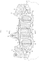
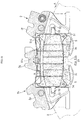
- FIGs. 1 to 3 are cross sectional views illustrating a vehicle disc brake according to a first embodiment of the invention.
- An arrow A indicates the direction in which the disc rotor rotates together with wheels in forward travel of a vehicle and a disc exit side and a disc entry side, which will be described below, assume that the vehicle travels forward.
- a vehicle disc brake 1 includes a disc rotor 2 rotating together with wheels, a caliper body 3 attached to the vehicle body on one side of the disc rotor 2, and friction pads 4 and 4 disposed on both sides of the disc rotor 2.
- the caliper body 3 is formed in a six-pot opposed-piston type having a monocoque structure in which a pair of acting parts 3a and 3a pushing the friction pads 4 and 4 is integrally formed with a bridge part 3b straddling the outer circumferential side of the disc rotor 2, and three cylinder holes 3c are formed in each of the acting parts 3a and 3a so as to face the three cylinder holes 3c formed in the other of the actingparts 3a and 3a.
- a piston 5 formed in a cup is movably inserted into each of the cylinder holes 3c so that its opening is oriented to the disc rotor 2.
- a dust seal 6a is attached to an inner circumferential part on the opening side
- a piston seal 6b is attached to the part closer to the bottom of the cylinder hole than the dust seal 6a
- a hydraulic chamber 7 is defined between each of the pistons 5 and each of the cylinder holes 3c.
- a torque reception part 3d with which a disc exit side surface 4a and a disc entry side surface 4b of the friction pad 4 make contact is formed in the inner side in the disc radial direction of the disc rotor side surface of each of the acting parts 3a.
- the bridge part 3b includes a disc exit side bridge part 3e disposed on the disc exit side, a disc entry side bridge part 3f disposed on the disc entry side, and a central bridge part 3g disposed in the middle of the disc exit side bridge part 3e and the disc entry side bridge part 3f, and a pad spring 8 for pushing the friction pads 4 and 4 against the disc inner circumferential side is attached to the central bridge part 3g.
- the torque reception parts 3d have four pad guide grooves 9 facing each other in each of the side parts of the disc rotor 2.
- Each of the pad guide grooves 9 is formed in a U-shape including a disc radial direction outer side surface 9a, a disc radial direction inner side surface 9b, and a facing surface 9c connecting the disc radial direction outer side surface 9a to the disc radial direction inner side surface 9b.
- a caliper side recess 9d (incorrect installation preventing part of the invention) concave toward the disc entry side and the outer side in the disc radial direction is formed in the part (close to the caliper body center) of the disc radial direction outer side surface 9a of the pad guide groove 9 on the disc entry side
- a caliper side recess 9e (incorrect installation preventing part of the invention) concave toward the disc exit side and the outer side in the disc radial direction is formed in the part (close to the caliper body center) of the disc radial direction outer side surface 9a of the pad guide groove 9 on the disc exit side.
- the friction pads 4 and 4 are disposed between the acting parts 3a and the disc rotor 2 and each of the friction pads 4 and 4 includes four linings 4c in slidable contact with the disc rotor 2 and a back plate 4d made of metal on which the linings 4c are pasted.
- the back plate 4d has a pair of tabs 10 and 11, the tab 10 protruding on the disc entry side, the tab 11 protruding on the disc exit side.
- a tab side protrusion 10a (incorrect installation preventing part of the invention) that is convex toward the disc entry side and the outer side in the disc radial direction and has a shape corresponding to the caliper side recess 9d is formed in the part (close to the caliper body center) of the disc radial direction outer side surface of the tab 10 on the disc entry side
- a tab side protrusion 11a (incorrect installation preventing part of the invention) that is convex toward the disc exit side and the outer side in the disc radial direction and corresponds to the caliper side recess 9d is formed in the part (close to the caliper body center) of the disc radial direction outer side surface of the tab 11 on the disc exit side.
- the friction pads 4 are supported movably in the disc axial direction by housing the tabs 10 and 11 in the pad guide grooves 9 and 9 formed in the caliper body 3 and this omits hanger pins for hanging the friction pads.
- the caliper side recesses are provided in the pad guide grooves and the tab side protrusions are provided on the tabs as the incorrect installation preventing part.
- the caliper side protrusions may be provided in the pad guide grooves and tab side recesses having shapes corresponding to the caliper side protrusions may be provided in the tabs.
- recesses and protrusions as the incorrect installation preventing part may be formed in the tabs and the pad guide grooves in either the disc entry side or the disc exit side. In this case, even if an attempt is made to insert the tabs into the pad guide grooves with the front and the back of the friction pads reversed by mistake, the tabs cannot be inserted into the pad guide grooves, thereby preventing the incorrect installation of the friction pads.
- Figs. 4 to 11 illustrate other embodiments of the invention and the same components as in the first embodiment are indicated by the same reference numerals and detailed descriptions are omitted.
- Figs. 4 and 5 illustrate the second embodiment of the invention
- the caliper body 3 according to the embodiment is formed by abutting the pair of acting parts 3a and 3a against each other via the bridge part 3b (this has no problem because the bridge part 3b is formed by integrating 3e, 3f, and 3g) straddling the outer circumferential side of the disc rotor 2 and coupling them with a coupling bolt
- the caliper body 3 is formed in a four-pot opposed-piston type
- the two cylinder holes 3c are formed in each of the acting parts 3a and 3a so as to face each other.
- the piston 5 formed in a cup is movably inserted into each of the cylinder holes 3c with its opening oriented to the disc rotor 2.
- the torque reception part 3d with which a disc exit side surface 21b and a disc entry side surface 21a of a friction pad 21 make contact is formed on the inner side in the disc radial direction of the disc rotor side surface of each of the acting parts 3a and the torque reception part 3d is provided with four pad guide grooves 22 facing each other in the side parts of the disc rotor 2.
- Each of the friction pads 21 and 21 includes a lining 21c in slidable contact with the disc rotor 2 and a back plate 21d made of metal on which the lining 21c is pasted, and a pair of tabs 23 and 23 protrude on the disc entry side and the disc exit side.
- a protrusion 24 protruding to the outer side in the disc rotor circumferential direction is formed at the disc radial direction inner side end of the disc entry side surface 21a of the back plate 21d.
- the protrusion 24 is disposed on the inner side in the disc radial direction of the inner end in the disc radial direction of the torque reception part 3d on the disc entry side of the caliper body 3 when the friction pad 21 is installed in the correct state, and the friction pads 21 and 21 can be installed to the caliper body 3 movably in the disc axial direction by inserting the tabs 23 and 23 of the friction pads 21 into the pad guide grooves 22 and 22 of the caliper body 3.
- a friction pad 31 according to the embodiment includes a lining 31a in slidable contact with the disc rotor 2 and a back plate 31b made of metal on which the lining 31a is pasted, and a pair of tabs 32 and 32 protrudes on the disc entry side and the disc exit side.
- a pair of protrusions 33 and 33 protruding to the outer side in the disc rotor circumferential direction is formed in the disc radial direction inner side end of a disc exit side surface 31c of the back plate 31b and the disc radial direction inner side end of the disc entry side surface 31d of the back plate 31b.
- the protrusions 33 and 33 are disposed on the inner side in the disc radial direction of the disc radial direction inner side end of the both torque reception parts 3d and 3d of the caliper body 3, and the friction pads 31 and 31 can be installed to the caliper body 3 movably in the disc axial direction by inserting the tabs 32 and 32 of the friction pads 31 into pad guide grooves 34 and 34 of the caliper body 3.
- the friction pads 31 and 31 can be installed to the caliper body 3 movably in the disc axial direction by inserting the tabs 32 and 32 of the friction pads 31 into pad guide grooves 34 and 34 of the caliper body 3.
- the pair of protrusions 33 and 33 provided in the friction pad 31 protrudes to the outer side in the disc rotor circumferential direction, the height of the protrusions 33 can be suppressed and the amount of exposure of the protrusions 33 and 33 from the caliper body 3 can be reduced as compared with the protrusions 24 of the second embodiment, so the appearance can be kept good by making the protrusions 33 and 33 inconspicuous.
- Figs. 8 and 9 illustrate a fourth embodiment of the invention and a friction pad 41 according to the embodiment includes a lining 41a in slidable contact with the disc rotor 2 and a back plate 41b made of metal on which the lining 41a is pasted, and a pair of tabs 42 and 42 protrudes on the disc entry side and the disc exit side.
- the back plate 41b is formed so that a width L1 from a disc exit side surface 41c to a disc entry side surface 41d on the outer side in the disc radial direction of the tabs 42 and 42 is smaller than a width L2 from a disc exit side surface 41e to a disc entry side surface 41f on the inner side in the disc radial direction.
- Torque reception parts 3h and 3h provided in the acting parts 3a and 3a of the caliper body 3 have pad guide grooves 43 and 43 in the intermediate part in the disc radial direction and are formed in a step in which the length L3 between the torque reception parts 3h and 3h, facing each other across the friction pad 41, that are disposed on the outer side in the disc radial direction of the pad guide grooves 43 and 43 are smaller than the length L4 between the torque reception parts 3h and 3h, facing each other across the friction pad 41, that are disposed on the inner side in the disc radial direction of the pad guide grooves 43 and 43 depending on the shape of the back plate 41b.
- a small width part on the outer side in the disc radial direction of the tabs 42 and 42 of the back plate 41b is disposed in the part having a short length between the torque reception parts 3h and 3h and a wide width part on the inner side in the disc radial direction of the tabs 42 and 42 is disposed in the part having a long length between the torque reception parts 3h and 3h, so that the friction pads 41 and 41 can be installed to the caliper body 3 movably in the disc axial direction by inserting the tabs 42 and 42 into the pad guide grooves 43 and 43.
- the width from the disc exit side surface to the disc entry side surface on the inner side in the disc radial direction of the tabs of the back plates of the friction pads may be smaller than the width from the disc exit side surface to the disc entry side surface on the outer side in the disc radial direction of the tabs and, depending on the shapes of the back plates, the length between the torque reception parts facing each other across the friction pads on the inner side in the disc radial direction of the pad guide grooves may be smaller than the length between the torque reception parts facing each other across the friction pads on the outer side in the disc radial direction of the pad guide grooves to form a step.
- a friction pad 51 according to the embodiment includes a lining 51a in slidable contact with the disc rotor 2 and a metal back plate 51b on which the lining 51a is pasted, and a pair of tabs 52 and 52 protrudes on the disc entry side and the disc exit side.
- the positions in which the tabs 52 and 52 are formed and the positions of pad guide grooves 53 and 53 formed in the torque reception parts 3d and 3d are determined so that a disc radial direction inner side surface 51c of the friction pad 51 bumps against the central bridge part 3g of the caliper body 3 when the friction pad 51 is installed with the disc inner circumferential side and the disc outer circumferential side reversed by mistake and the tabs 52 and 52 are formed on the outer side in the disc radial direction of the back plate 51b of the friction pad 51 and the pad guide grooves 53 and 53 are formed on the outer side in the disc radial direction of the torque reception part 3d and 3d.
- the positions in which the tabs 52 and 52 and the pad guide grooves 53 and 53 are formed may be present on the inner side in the disc radial direction to which a disc radial direction outer side surface 51d of the friction pad 51 protrudes from the disc inner circumferential side of the caliper body 3 when the friction pad 51 is installed with the disc inner circumferential side and the disc outer circumferential side reversed by mistake.
- the friction pads are visually identified from the disc inner circumferential side of the caliper body 3 in the case of incorrect installation, incorrect installation can be prevented.
- the invention is not limited to the above embodiments, which are of six-pot or four-pot opposed-piston type, and applicable to two-pot or eight-or-more-pot opposed piston type.
- the invention is applicable regardless of the structure of a caliper body or a friction pad as long as friction pads can be installed to the caliper body movably in the disc axial direction by inserting the tabs of the friction pads into the pad guide grooves of the caliper body.
Landscapes
- Engineering & Computer Science (AREA)
- General Engineering & Computer Science (AREA)
- Mechanical Engineering (AREA)
- Braking Arrangements (AREA)
Abstract
Description
- The present invention relates to a vehicle disc brake and, more particularly, to a vehicle disc brake in which a pair of tabs provided on friction pads are housed in pad guide grooves formed in a caliper body and the friction pads are supported movably in a disc axial direction.
- Conventionally, there is a vehicle disc brake that has a caliper body provided with acting parts having cylinder holes opened toward a disc rotor and a pair of friction pads disposed on both sides of the disc rotor, in which each of the friction pads has a pair of tabs on the disc entry side and the disc exit side of the back plates of the friction pads in forward travel of the vehicle and the friction pads are supported movably in a disc axial direction by housing the tabs in pad guide grooves formed in a caliper body (see, for example, PTL 1).
- PTL 1:
JP-A-2014-74500 - Although
Fig. 8 ofPTL 1 above illustrates the installation of a friction pad (brake pad 80) in a caliper body 72, the friction pad can also be installed in the caliper body with the friction pad reversed, possibly causing so-called incorrect installation.Fig. 11 easily illustrates the problem with incorrect installation. As is clear from the disc brake illustrated inFig. 11 , even in the state in which the disc outer circumferential side and the disc inner circumferential side of afriction pad 61 are reversed,tabs friction pad 61 can be inserted intopad guide grooves caliper body 63, as illustrated in dashed lines. - An object of the invention is to provide a vehicle disc brake capable of preventing the incorrect installation of friction pads using a simple structure.
- To achieve the above object, the vehicle disc brake according to the invention includes a caliper body provided with an acting part having a cylinder hole open toward a disc rotor and a pair of friction pads disposed on both sides of the disc rotor, each of the friction pads having a pair of tabs on a disc entry side and a disc exit side in forward travel of a vehicle, the friction pads being supported movably in a disc axial direction by housing the tabs in pad guide grooves formed in a caliper body, in which an incorrect installation preventing part is provided so as to prevent incorrect installation by bumping against the caliper body or the tabs when the friction pads are installed in the pad guide grooves in an incorrect orientation.
- In addition, preferably, the incorrect installation preventing part is formed by a caliper side recess or a caliper side protrusion formed in each of the pad guide grooves and a tab side protrusion having a shape corresponding to the caliper side recess or a tab side recess having a shape corresponding to the caliper side protrusion formed in each of the tabs and, when the friction pads are installed in the incorrect orientation, the caliper side protrusion bumps against the tab or the tab side protrusion bumps against the pad guide groove.
- In addition, preferably, the incorrect installation preventing part is formed by a protrusion protruding in a disc rotor circumferential direction, the protrusion being provided in a disc radial direction inner side end of the disc exit side surface or the disc entry side surface of each of the friction pads in forward travel of the vehicle, and the protrusion bumps against the caliper body when the friction pads are installed in the incorrect orientation.
- In addition, preferably, the incorrect installation preventing part is formed by a pair of protrusions protruding in a disc rotor circumferential direction, the protrusions being provided in the disc radial direction inner side end of the disc exit side surface or the disc entry side surface of each of the friction pads in forward travel of the vehicle, and the protrusions bump against the caliper body when the friction pads are installed in the incorrect orientation.
- In addition, preferably, the vehicle disc brake includes a caliper body provided with an acting part having a cylinder hole open toward a disc rotor, the acting part having a torque reception part making contact with a disc exit side surface or a disc entry side surface of each of the friction pads in forward travel of a vehicle and receiving a braking torque, pad guide grooves are provided in an intermediate part in a disc radial direction of the torque reception part and a pair of friction pads disposed on both sides of the disc rotor, each of the friction pads having a pair of tabs on a disc entry side and a disc exit side of a back plate in forward travel of the vehicle, the friction pads being supported movably in a disc axial direction by housing the tabs in pad guide grooves, in which the friction pads are formed to have different widths from the disc exit side surface to the disc entry side surface of the back plate in forward travel of the vehicle between an outer side and an inner side in the disc radial direction of the tabs, the torque reception part is formed to have different lengths between the torque reception parts facing each other across the friction pads so as to correspond to the shape of the back plate between the outer side and the inner side in the disc radial direction of the pad guide grooves, and the back plate bumps against the caliper body when the friction pads are installed in an incorrect orientation.
- In addition, preferably, the vehicle disc brake includes a caliper body provided with an acting part having a cylinder hole open toward a disc rotor and a bridge part straddling an outer circumference of the disc rotor, the acting part having a torque reception part making contact with a disc exit side surface or a disc entry side surface of each of the friction pads in forward travel of a vehicle and receiving a braking torque, pad guide grooves are provided in an intermediate part in a disc radial direction of the torque reception part and a pair of friction pads disposed on both sides of the disc rotor, each of the friction pads having a pair of tabs on a disc entry side and a disc exit side of a back plate in forward travel of the vehicle, the friction pads being supported movably in a disc axial direction by housing the tabs in pad guide grooves, in which, when the friction pads are installed with a disc inner circumferential side and a disc outer circumferential side reversed by mistake, the tab are formed on the outer side in the disc radial direction of the back plate and the pad guide grooves are formed on the outer side in the disc radial direction of the torque reception part so that the disc inner circumferential side of the friction pads bumps against an inner surface of the bridge part.
- In the vehicle disc brake according to the invention, if the friction pads are installed in the caliper body in an incorrect orientation, the tabs of the friction pads cannot be inserted into the pad guide grooves due to a bump against the incorrect installation preventing part, thereby preventing incorrect installation.
- In addition, the incorrect installation preventing part is formed by the caliper side recesses or the caliper side protrusions formed in the pad guide grooves and the tab side protrusions or the tab side recesses, formed in the tabs, that have shapes corresponding to the caliper side recesses or the caliper side protrusions. Accordingly, when the friction pads are installed in the correct state, the friction pads can be installed to the caliper body by inserting the tab side protrusions into the caliper side recesses or inserting the caliper side protrusions into the tab side recesses and inserting the tabs of the friction pads into the pad guide grooves. In contrast, when an attempt is made to install the friction pads with the disc outer circumferential side and the disc inner circumferential side reversed by mistake, the caliper side protrusions bump against the tabs or the tab side protrusions bump against the pad guide grooves and the tabs cannot be inserted into the pad guide grooves, thereby preventing the incorrect installation of the friction pads.
- In addition, since the incorrect installation preventing part is formed by the protrusion, protruding in the disc rotor circumferential direction, that is provided at the disc radial direction inner side end of the disc exit side surface or the disc entry side surface of the friction pads in forward travel of the vehicle, the protrusions formed on the friction pads are disposed closer to the disc entry side than the caliper body when the friction pads are installed in the correct state and the friction pads can be installed to the caliper body without bumping against the caliper body. In contrast, when an attempt is made to install the friction pads with the disc outer circumferential side and the disc inner circumferential side reversed by mistake, the protrusions bump against the caliper body and the friction pads cannot be installed to the caliper body, thereby preventing incorrect installation.
- In addition, since the incorrect installation preventing part is formed by a pair of protrusions, protruding in the disc rotor circumferential direction, that is provided at the disc radial direction inner side end of the disc exit side surface and the disc entry side surface in forward travel of a vehicle, the protrusions formed on the friction pads are disposed closer to the disc entry side than the caliper body when the friction pads are installed in the correct state, so the friction pads can be installed to the caliper body without bumping against the caliper body. In contrast, when an attempt is made to install the friction pads with the disc outer circumferential side and the disc inner circumferential side reversed by mistake, the pair of protrusions bump against the caliper body and the friction pads cannot be installed to the caliper body, thereby preventing incorrect installation. In addition, since the protrusions are provided in two positions (the disc exit side surface and the disc entry side surface), even when an attempt is made to insert the tabs into the pad guide grooves in the state in which the disc outer circumferential side and the disc inner circumferential side of the friction pads are reversed and the tabs are inclined obliquely with respect to the caliper body, any of the protrusions bumps against the caliper body and incorrect installation can be surely prevented. In addition, since the amount of exposure from the caliper body can be reduced by reducing the height of the protrusions, the appearance can be kept good by making the protrusions inconspicuous.
- In addition, in back plates of the friction pads, the width between the disc exit side surface and the disc entry side surface in forward travel of the vehicle is different between the outer side in the disc radial direction of the tabs and the inner side in the disc radial direction of the tabs, the pad guide grooves are provided in an intermediate part in the disc radial direction of the torque reception parts, and the length between the torque reception parts facing each other across friction pads is different between the outer side in the disc radial direction of the pad guide grooves and the inner side in the disc radial direction of the pad guide grooves, so the friction pads can be installed appropriately because the shapes of the torque reception parts correspond to the shapes of the back plates of the friction pads when the friction pads are installed in the correct state. In contrast, when an attempt is made to install the friction pads with the disc outer circumferential side and the disc inner circumferential side reversed by mistake, the part having a large width from the disc exit side surface to the disc entry side surface of the back plate makes contact with the caliper body in the part having a small length between the torque reception parts facing each other across the friction pad and the friction pads cannot be installed to the caliper body, thereby preventing incorrect installation.
- In addition, the tabs are formed on the outer side in the disc radial direction of the back plate and the pad guide grooves are formed on the outer side in the disc radial direction of the torque reception part so that the disc inner circumferential side of the friction pad bumps against the bridge part of the caliper body when the friction pads are installed with the disc outer circumferential side and the disc inner circumferential side reversed by mistake, so the appearance can be kept good while preventing incorrect installation with a simple structure.
-
- [
Fig. 1] Fig. 1 is a cross sectional view illustrating the front of a vehicle disc brake according to a first embodiment of the invention. - [
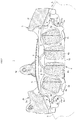
Fig. 2] Fig. 2 is an explanatory diagram illustrating a case in which an attempt is made to install a friction pad with a disc outer circumferential side and a disc inner circumferential side reversed. - [
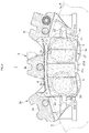
Fig. 3] Fig. 3 is a cross sectional view taken along line III-III inFig. 1 . - [
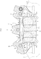
Fig. 4] Fig. 4 is a cross sectional view illustrating the front of a vehicle disc brake according to a second embodiment of the invention. - [
Fig. 5] Fig. 5 is an explanatory diagram illustrating a case in which an attempt is made to install a friction pad according to the second embodiment with a disc outer circumferential side and a disc inner circumferential side reversed. - [
Fig. 6] Fig. 6 is a cross sectional view illustrating the front of a vehicle disc brake according to a third embodiment of the invention. - [
Fig. 7] Fig. 7 is an explanatory diagram illustrating a case in which an attempt is made to install a friction pad according to the third embodiment with a disc outer circumferential side and a disc inner circumferential side reversed. - [
Fig. 8] Fig. 8 is a cross sectional view illustrating the front of a vehicle disc brake according to a fourth embodiment of the invention. - [
Fig. 9] Fig. 9 is an explanatory diagram illustrating a case in which an attempt is made to install a friction pad according to the fourth embodiment with a disc outer circumferential side and a disc inner circumferential side reversed. - [
Fig. 10] Fig. 10 is a cross sectional view illustrating the front of the vehicle disc brake according to the fourth embodiment of the invention. - [
Fig. 11] Fig. 11 is an explanatory diagram illustrating a conventional vehicle disc brake. -
Figs. 1 to 3 are cross sectional views illustrating a vehicle disc brake according to a first embodiment of the invention. An arrow A indicates the direction in which the disc rotor rotates together with wheels in forward travel of a vehicle and a disc exit side and a disc entry side, which will be described below, assume that the vehicle travels forward. - A
vehicle disc brake 1 according to the embodiment includes adisc rotor 2 rotating together with wheels, acaliper body 3 attached to the vehicle body on one side of thedisc rotor 2, andfriction pads disc rotor 2. - The
caliper body 3 is formed in a six-pot opposed-piston type having a monocoque structure in which a pair of actingparts friction pads bridge part 3b straddling the outer circumferential side of thedisc rotor 2, and threecylinder holes 3c are formed in each of the actingparts cylinder holes 3c formed in the other of theactingparts piston 5 formed in a cup is movably inserted into each of thecylinder holes 3c so that its opening is oriented to thedisc rotor 2. In each of thecylinder holes 3c, adust seal 6a is attached to an inner circumferential part on the opening side, apiston seal 6b is attached to the part closer to the bottom of the cylinder hole than thedust seal 6a, and ahydraulic chamber 7 is defined between each of thepistons 5 and each of thecylinder holes 3c. In addition, atorque reception part 3d with which a discexit side surface 4a and a discentry side surface 4b of thefriction pad 4 make contact is formed in the inner side in the disc radial direction of the disc rotor side surface of each of the actingparts 3a. In addition, thebridge part 3b includes a disc exitside bridge part 3e disposed on the disc exit side, a disc entryside bridge part 3f disposed on the disc entry side, and acentral bridge part 3g disposed in the middle of the disc exitside bridge part 3e and the disc entryside bridge part 3f, and apad spring 8 for pushing thefriction pads central bridge part 3g. - The
torque reception parts 3d have fourpad guide grooves 9 facing each other in each of the side parts of thedisc rotor 2. Each of thepad guide grooves 9 is formed in a U-shape including a disc radial directionouter side surface 9a, a disc radial directioninner side surface 9b, and a facingsurface 9c connecting the disc radial directionouter side surface 9a to the disc radial directioninner side surface 9b. In addition, a caliper side recess 9d (incorrect installation preventing part of the invention) concave toward the disc entry side and the outer side in the disc radial direction is formed in the part (close to the caliper body center) of the disc radial directionouter side surface 9a of thepad guide groove 9 on the disc entry side and a caliper side recess 9e (incorrect installation preventing part of the invention) concave toward the disc exit side and the outer side in the disc radial direction is formed in the part (close to the caliper body center) of the disc radial directionouter side surface 9a of thepad guide groove 9 on the disc exit side. - The
friction pads parts 3a and thedisc rotor 2 and each of thefriction pads linings 4c in slidable contact with thedisc rotor 2 and aback plate 4d made of metal on which thelinings 4c are pasted. Theback plate 4d has a pair oftabs tab 10 protruding on the disc entry side, thetab 11 protruding on the disc exit side. Atab side protrusion 10a (incorrect installation preventing part of the invention) that is convex toward the disc entry side and the outer side in the disc radial direction and has a shape corresponding to thecaliper side recess 9d is formed in the part (close to the caliper body center) of the disc radial direction outer side surface of thetab 10 on the disc entry side atab side protrusion 11a (incorrect installation preventing part of the invention) that is convex toward the disc exit side and the outer side in the disc radial direction and corresponds to thecaliper side recess 9d is formed in the part (close to the caliper body center) of the disc radial direction outer side surface of thetab 11 on the disc exit side. Thefriction pads 4 are supported movably in the disc axial direction by housing thetabs pad guide grooves caliper body 3 and this omits hanger pins for hanging the friction pads. - In the
vehicle disc brake 1 according to the embodiment formed as described above, as illustrated inFigs. 1 and3 , when thefriction pads 4 are installed in the correct state, thetab side protrusions friction pads caliper side recesses pad guide grooves friction pads caliper body 3 movably in the disc axial direction. In contrast, as illustrated inFig. 2 , when an attempt is made to install thefriction pads tab side protrusions inner side surfaces pad guide grooves tabs outer side surfaces tabs pad guide grooves friction pads - In the above embodiment, the caliper side recesses are provided in the pad guide grooves and the tab side protrusions are provided on the tabs as the incorrect installation preventing part. Conversely, however, the caliper side protrusions may be provided in the pad guide grooves and tab side recesses having shapes corresponding to the caliper side protrusions may be provided in the tabs. In addition, recesses and protrusions as the incorrect installation preventing part may be formed in the tabs and the pad guide grooves in either the disc entry side or the disc exit side. In this case, even if an attempt is made to insert the tabs into the pad guide grooves with the front and the back of the friction pads reversed by mistake, the tabs cannot be inserted into the pad guide grooves, thereby preventing the incorrect installation of the friction pads.
-
Figs. 4 to 11 illustrate other embodiments of the invention and the same components as in the first embodiment are indicated by the same reference numerals and detailed descriptions are omitted.Figs. 4 and5 illustrate the second embodiment of the invention, thecaliper body 3 according to the embodiment is formed by abutting the pair of actingparts bridge part 3b (this has no problem because thebridge part 3b is formed by integrating 3e, 3f, and 3g) straddling the outer circumferential side of thedisc rotor 2 and coupling them with a coupling bolt, thecaliper body 3 is formed in a four-pot opposed-piston type, and the twocylinder holes 3c are formed in each of the actingparts piston 5 formed in a cup is movably inserted into each of the cylinder holes 3c with its opening oriented to thedisc rotor 2. In addition, thetorque reception part 3d with which a discexit side surface 21b and a discentry side surface 21a of afriction pad 21 make contact is formed on the inner side in the disc radial direction of the disc rotor side surface of each of the actingparts 3a and thetorque reception part 3d is provided with fourpad guide grooves 22 facing each other in the side parts of thedisc rotor 2. - Each of the
friction pads lining 21c in slidable contact with thedisc rotor 2 and aback plate 21d made of metal on which thelining 21c is pasted, and a pair oftabs entry side surface 21a of theback plate 21d. - In the embodiment, as illustrated in
Fig. 4 , theprotrusion 24 is disposed on the inner side in the disc radial direction of the inner end in the disc radial direction of thetorque reception part 3d on the disc entry side of thecaliper body 3 when thefriction pad 21 is installed in the correct state, and thefriction pads caliper body 3 movably in the disc axial direction by inserting thetabs friction pads 21 into thepad guide grooves caliper body 3. In contrast, as illustrated inFig. 5 , when an attempt is made to install thefriction pads protrusion 24 bumps against thetorque reception part 3d on the disc exit side of the caliper body and thetabs pad guide grooves friction pads -
Figs. 6 and7 illustrate a third embodiment of the invention, afriction pad 31 according to the embodiment includes alining 31a in slidable contact with thedisc rotor 2 and aback plate 31b made of metal on which thelining 31a is pasted, and a pair oftabs protrusions 33 and 33 (incorrect installation preventing part of the invention) protruding to the outer side in the disc rotor circumferential direction is formed in the disc radial direction inner side end of a discexit side surface 31c of theback plate 31b and the disc radial direction inner side end of the discentry side surface 31d of theback plate 31b. - In the embodiment, as illustrated in
Fig. 6 , when thefriction pad 31 is installed in the correct state, theprotrusions torque reception parts caliper body 3, and thefriction pads caliper body 3 movably in the disc axial direction by inserting thetabs friction pads 31 intopad guide grooves caliper body 3. In contrast, as illustrated inFig. 7 , when an attempt is made to install thefriction pads protrusions torque reception parts caliper body 3, respectively, and thetabs pad guide grooves friction pads - In addition, in the embodiment, even when an attempt is made to insert the
tabs pad guide grooves friction pads tabs caliper body 3, any of theprotrusions caliper body 3 and incorrect installation can be surely prevented. In addition, since the pair ofprotrusions friction pad 31 protrudes to the outer side in the disc rotor circumferential direction, the height of theprotrusions 33 can be suppressed and the amount of exposure of theprotrusions caliper body 3 can be reduced as compared with theprotrusions 24 of the second embodiment, so the appearance can be kept good by making theprotrusions -
Figs. 8 and9 illustrate a fourth embodiment of the invention and afriction pad 41 according to the embodiment includes alining 41a in slidable contact with thedisc rotor 2 and aback plate 41b made of metal on which thelining 41a is pasted, and a pair oftabs back plate 41b is formed so that a width L1 from a discexit side surface 41c to a discentry side surface 41d on the outer side in the disc radial direction of thetabs exit side surface 41e to a discentry side surface 41f on the inner side in the disc radial direction. -
Torque reception parts parts caliper body 3 havepad guide grooves torque reception parts friction pad 41, that are disposed on the outer side in the disc radial direction of thepad guide grooves torque reception parts friction pad 41, that are disposed on the inner side in the disc radial direction of thepad guide grooves back plate 41b. - In the embodiment, as illustrated in
Fig. 8 , when thefriction pad 41 is installed in the correct state, a small width part on the outer side in the disc radial direction of thetabs back plate 41b is disposed in the part having a short length between thetorque reception parts tabs torque reception parts friction pads caliper body 3 movably in the disc axial direction by inserting thetabs pad guide grooves Fig. 9 , when an attempt is made to install thefriction pads exit side surface 41e and the discentry side surface 41f of theback plate 41b bumps against the part of thecaliper body 3 having a small length between thetorque reception parts tabs pad guide grooves friction pads - In the invention, the width from the disc exit side surface to the disc entry side surface on the inner side in the disc radial direction of the tabs of the back plates of the friction pads may be smaller than the width from the disc exit side surface to the disc entry side surface on the outer side in the disc radial direction of the tabs and, depending on the shapes of the back plates, the length between the torque reception parts facing each other across the friction pads on the inner side in the disc radial direction of the pad guide grooves may be smaller than the length between the torque reception parts facing each other across the friction pads on the outer side in the disc radial direction of the pad guide grooves to form a step.
-
Fig. 10 indicates a fifth embodiment of the invention, afriction pad 51 according to the embodiment includes alining 51a in slidable contact with thedisc rotor 2 and a metal backplate 51b on which thelining 51a is pasted, and a pair oftabs - The positions in which the
tabs pad guide grooves torque reception parts inner side surface 51c of thefriction pad 51 bumps against thecentral bridge part 3g of thecaliper body 3 when thefriction pad 51 is installed with the disc inner circumferential side and the disc outer circumferential side reversed by mistake and thetabs back plate 51b of thefriction pad 51 and thepad guide grooves torque reception part - In addition, the positions in which the
tabs pad guide grooves outer side surface 51d of thefriction pad 51 protrudes from the disc inner circumferential side of thecaliper body 3 when thefriction pad 51 is installed with the disc inner circumferential side and the disc outer circumferential side reversed by mistake. In this case, since the friction pads are visually identified from the disc inner circumferential side of thecaliper body 3 in the case of incorrect installation, incorrect installation can be prevented. - The invention is not limited to the above embodiments, which are of six-pot or four-pot opposed-piston type, and applicable to two-pot or eight-or-more-pot opposed piston type. In addition, the invention is applicable regardless of the structure of a caliper body or a friction pad as long as friction pads can be installed to the caliper body movably in the disc axial direction by inserting the tabs of the friction pads into the pad guide grooves of the caliper body.
-
- 1:
- vehicle disc brake
- 2:
- disc rotor
- 3:
- caliper body
- 3a:
- acting part
- 3b:
- bridge part
- 3c:
- cylinder hole
- 3d, 3h:
- torque reception part
- 3e:
- disc exit side bridge part
- 3f:
- disc entry side bridge part
- 3g:
- central bridge part
- 4:
- piston
- 4a:
- disc exit side surface
- 4b:
- disc entry side surface
- 4c:
- lining
- 4d:
- back plate
- 5:
- piston
- 6a:
- dust seal
- 6b:
- piston seal
- 7:
- hydraulic chamber
- 8:
- pad spring
- 9:
- pad guide groove
- 9a:
- disc radial direction outer side surface
- 9b:
- disc radial direction inner side surface
- 9c:
- facing surface
- 9d, 9e:
- caliper side recess
- 10, 11:
- tab
- 10a, 11a:
- tab side protrusion
- 21:
- friction pad
- 21a:
- disc entry side surface
- 21b:
- disc exit side surface
- 21c:
- lining
- 21d:
- back plate
- 22:
- pad guide groove
- 23:
- tab
- 24:
- protrusion
- 31:
- friction pad
- 31a:
- lining
- 31b:
- back plate
- 31c:
- disc exit side surface
- 31d:
- disc entry side surface
- 32:
- tab
- 33:
- protrusion
- 34:
- pad guide groove
- 41:
- friction pad
- 41a:
- lining
- 41b:
- back plate
- 41c, 41e:
- disc exit side surface
- 41d, 41f:
- disc entry side surface
- 42:
- tab
- 43:
- pad guide groove
- 51:
- friction pad
- 51a:
- lining
- 51b:
- back plate
- 51c:
- disc radial direction inner side surface
- 51d:
- disc radial direction outer side surface
- 52:
- tab
- 53:
- pad guide groove
Claims (6)
- A vehicle disc brake comprising:a caliper body provided with an acting part having a cylinder hole open toward a disc rotor; anda pair of friction pads disposed on both sides of the disc rotor, each of the friction pads having a pair of tabs on a disc entry side and a disc exit side of a back plate in forward travel of a vehicle, the friction pads being supported movably in a disc axial direction by housing the tabs in pad guide grooves formed in the caliper body,wherein an incorrect installation preventing parts is provided so as to prevent incorrect installation by bumping against the caliper body or the tabs when the friction pads are installed in the pad guide grooves in an incorrect orientation.
- The vehicle disc brake according to claim 1,
wherein the incorrect installation preventing part is formed by a caliper side recess or a caliper side protrusion formed in each of the pad guide grooves and a tab side protrusion having a shape corresponding to the caliper side recess or a tab side recess having a shape corresponding to the caliper side protrusion formed in each of the tabs and, when the friction pads are installed in the incorrect orientation, the caliper side protrusion bumps against the tab or the tab side protrusion bumps against the pad guide groove. - The vehicle disc brake according to claim 1,
wherein the incorrect installation preventing part is formed by a protrusion protruding in a disc rotor circumferential direction, the protrusion being provided in a disc radial direction inner side end of the disc exit side surface or the disc entry side surface of each of the friction pads in forward travel of the vehicle, and the protrusion bumps against the caliper body when the friction pads are installed in the incorrect orientation. - The vehicle disc brake according to claim 1,
wherein the incorrect installation preventing part is formed by a pair of protrusions protruding in a disc rotor circumferential direction, the protrusions being provided in a disc radial direction inner side end of the disc exit side surface or the disc entry side surface of each of the friction pads in forward travel of the vehicle, and the protrusions bump against the caliper body when the friction pads are installed in the incorrect orientation. - A vehicle disc brake comprising:a caliper body provided with an acting part having a cylinder hole open toward a disc rotor, the acting part having a torque reception part making contact with a disc exit side surface or a disc entry side surface of each of the friction pads in forward travel of a vehicle and receiving a braking torque, pad guide grooves are provided in an intermediate part in a disc radial direction of the torque reception part; anda pair of friction pads disposed on both sides of the disc rotor, each of the friction pads having a pair of tabs on a disc entry side and a disc exit side of a back plate in forward travel of the vehicle, the friction pads being supported movably in a disc axial direction by housing the tabs in the pad guide grooves,wherein the friction pads are formed to have different widths from the disc exit side surface to the disc entry side surface of the back plate in forward travel of the vehicle between an outer side and an inner side in the disc radial direction of the tabs, the torque reception part is formed to have different lengths between the torque reception parts facing each other across the friction pads so as to correspond to the shape of the back plate between the outer side and the inner side in the disc radial direction of the pad guide grooves, and the back plate bumps against the caliper body when the friction pads are installed in an incorrect orientation.
- A vehicle disc brake comprising:a caliper body provided with an acting part having a cylinder hole open toward a disc rotor and a bridge part straddling an outer circumference of the disc rotor, the acting part having a torque reception part making contact with a disc exit side surface or a disc entry side surface of each of the friction pads in forward travel of a vehicle and receiving a braking torque, pad guide grooves are provided in an intermediate part in a disc radial direction of the torque reception part; anda pair of friction pads disposed on both sides of the disc rotor, each of the friction pads having a pair of tabs on a disc entry side and a disc exit side of a back plate in forward travel of the vehicle, the friction pads being supported movably in a disc axial direction by housing the tabs in pad guide grooves,wherein, when the friction pads are installed with a disc inner circumferential side and a disc outer circumferential side reversed by mistake, the tabs are formed on the outer side in the disc radial direction of the back plate and the pad guide grooves are formed on the outer side in the disc radial direction of the torque reception part so that the disc inner circumferential side of the friction pads bumps against an inner surface of the bridge part.
Applications Claiming Priority (3)
| Application Number | Priority Date | Filing Date | Title |
|---|---|---|---|
| JP2014261903 | 2014-12-25 | ||
| JP2015211664 | 2015-10-28 | ||
| PCT/JP2015/084933 WO2016104219A1 (en) | 2014-12-25 | 2015-12-14 | Vehicle disc brake |
Publications (3)
| Publication Number | Publication Date |
|---|---|
| EP3242051A1 true EP3242051A1 (en) | 2017-11-08 |
| EP3242051A4 EP3242051A4 (en) | 2018-09-12 |
| EP3242051B1 EP3242051B1 (en) | 2020-12-30 |
Family
ID=56150247
Family Applications (1)
| Application Number | Title | Priority Date | Filing Date |
|---|---|---|---|
| EP15872788.3A Active EP3242051B1 (en) | 2014-12-25 | 2015-12-14 | Vehicle disc brake |
Country Status (8)
| Country | Link |
|---|---|
| US (2) | US11098772B2 (en) |
| EP (1) | EP3242051B1 (en) |
| JP (1) | JP6433510B2 (en) |
| CN (1) | CN107110262B (en) |
| BR (1) | BR112017013586B1 (en) |
| ES (1) | ES2860704T3 (en) |
| TW (1) | TWI668379B (en) |
| WO (1) | WO2016104219A1 (en) |
Cited By (1)
| Publication number | Priority date | Publication date | Assignee | Title |
|---|---|---|---|---|
| US12595020B2 (en) | 2023-01-26 | 2026-04-07 | Shimano Inc. | Disc brake caliper of human-powered vehicle |
Families Citing this family (8)
| Publication number | Priority date | Publication date | Assignee | Title |
|---|---|---|---|---|
| CN107110262B (en) * | 2014-12-25 | 2019-03-12 | 日信工业株式会社 | Disc brakes for vehicles |
| WO2019240117A1 (en) * | 2018-06-15 | 2019-12-19 | 日信工業株式会社 | Vehicular disc brake |
| CN110966320B (en) * | 2018-09-30 | 2021-07-20 | 长城汽车股份有限公司 | Brakes and Vehicles for Vehicles |
| JP1677175S (en) * | 2020-04-06 | 2021-01-18 | ||
| JP1677174S (en) * | 2020-04-06 | 2021-01-18 | ||
| DE112021004458T5 (en) * | 2020-08-25 | 2023-06-07 | Hitachi Astemo, Ltd. | disc brake device |
| USD950444S1 (en) * | 2020-09-22 | 2022-05-03 | Hitachi Astemo, Ltd. | Disk brake friction pad for vehicles |
| JP7737814B2 (en) * | 2021-05-20 | 2025-09-11 | ナブテスコ株式会社 | Pad holder and brake caliper device for railway vehicles |
Family Cites Families (20)
| Publication number | Priority date | Publication date | Assignee | Title |
|---|---|---|---|---|
| JPS60576B2 (en) * | 1977-03-03 | 1985-01-09 | 住友電気工業株式会社 | disc brake |
| GB1545644A (en) | 1976-07-28 | 1979-05-10 | Sumitomo Electric Industries | Caliper disc brakes |
| JPS6123538U (en) | 1984-07-19 | 1986-02-12 | 曙ブレーキ工業株式会社 | disc brake |
| JP2910524B2 (en) * | 1993-09-08 | 1999-06-23 | トヨタ自動車株式会社 | Disc brake device |
| DE4340454A1 (en) * | 1993-11-27 | 1995-06-01 | Teves Gmbh Alfred | Brake pad set for floating caliper disc brake |
| JP3198397B2 (en) * | 1994-07-06 | 2001-08-13 | 日信工業株式会社 | Disc brakes for vehicles |
| DE19652936A1 (en) * | 1996-12-02 | 1998-06-04 | Teves Gmbh Alfred | Part-lining disc brake for motor vehicle |
| DE10108973A1 (en) | 2001-02-24 | 2002-09-05 | Bosch Gmbh Robert | Brake pad holder for a disc brake |
| GB0317897D0 (en) * | 2003-07-31 | 2003-09-03 | Ap Hydraulics Ltd | Disc brake calipers |
| WO2005064188A1 (en) * | 2003-12-30 | 2005-07-14 | Freni Brembo S.P.A. | Brake pad and caliper for a disc brake |
| DE102006003748B4 (en) * | 2006-01-26 | 2017-01-26 | Knorr-Bremse Systeme für Nutzfahrzeuge GmbH | Disc brake, in particular for a commercial vehicle |
| JP4682094B2 (en) * | 2006-06-22 | 2011-05-11 | 西日本旅客鉄道株式会社 | Disc brake device for railway vehicles that prevents erroneous mounting of brake pads |
| JP2008144889A (en) * | 2006-12-12 | 2008-06-26 | Advics:Kk | Disk brake |
| CN201071891Y (en) * | 2007-07-24 | 2008-06-11 | 浙江诸暨万宝机械有限公司 | Air pressure disc type brake of automobile |
| JP4713651B2 (en) | 2009-03-31 | 2011-06-29 | 日信工業株式会社 | Vehicle disc brake |
| US20120043168A1 (en) | 2010-08-18 | 2012-02-23 | Akebono Corporation (North America) | Brake systems, caliper assemblies and pads incorporating differential abutments |
| US8973240B2 (en) * | 2012-08-17 | 2015-03-10 | Bendix Spicer Foundation Brake Llc | Disc brake pad mounting and retention system and method |
| US9328785B2 (en) * | 2013-03-15 | 2016-05-03 | Hb Performance Systems, Inc. | Tensioned brake pad |
| JP5789311B2 (en) | 2014-01-30 | 2015-10-07 | 曙ブレーキ工業株式会社 | Assembly with protective clip and caliper body |
| CN107110262B (en) * | 2014-12-25 | 2019-03-12 | 日信工业株式会社 | Disc brakes for vehicles |
-
2015
- 2015-12-14 CN CN201580070898.2A patent/CN107110262B/en active Active
- 2015-12-14 US US15/538,997 patent/US11098772B2/en active Active
- 2015-12-14 BR BR112017013586-8A patent/BR112017013586B1/en active IP Right Grant
- 2015-12-14 WO PCT/JP2015/084933 patent/WO2016104219A1/en not_active Ceased
- 2015-12-14 JP JP2016566126A patent/JP6433510B2/en active Active
- 2015-12-14 ES ES15872788T patent/ES2860704T3/en active Active
- 2015-12-14 EP EP15872788.3A patent/EP3242051B1/en active Active
- 2015-12-22 TW TW104143186A patent/TWI668379B/en active
-
2021
- 2021-07-23 US US17/384,028 patent/US11668358B2/en active Active
Cited By (1)
| Publication number | Priority date | Publication date | Assignee | Title |
|---|---|---|---|---|
| US12595020B2 (en) | 2023-01-26 | 2026-04-07 | Shimano Inc. | Disc brake caliper of human-powered vehicle |
Also Published As
| Publication number | Publication date |
|---|---|
| CN107110262B (en) | 2019-03-12 |
| US20210348660A1 (en) | 2021-11-11 |
| US11668358B2 (en) | 2023-06-06 |
| ES2860704T3 (en) | 2021-10-05 |
| CN107110262A (en) | 2017-08-29 |
| WO2016104219A1 (en) | 2016-06-30 |
| TW201631264A (en) | 2016-09-01 |
| US20170356511A1 (en) | 2017-12-14 |
| TWI668379B (en) | 2019-08-11 |
| EP3242051A4 (en) | 2018-09-12 |
| BR112017013586B1 (en) | 2022-10-18 |
| US11098772B2 (en) | 2021-08-24 |
| BR112017013586A2 (en) | 2018-03-06 |
| JP6433510B2 (en) | 2018-12-05 |
| EP3242051B1 (en) | 2020-12-30 |
| BR112017013586A8 (en) | 2022-09-06 |
| JPWO2016104219A1 (en) | 2017-10-19 |
Similar Documents
| Publication | Publication Date | Title |
|---|---|---|
| US11668358B2 (en) | Vehicle disc brake | |
| EP2757281B1 (en) | Pad assembly for disk brake | |
| US3841444A (en) | Disc brake with anti-rattle spring hold down means | |
| US4082166A (en) | Disc brake having retention device | |
| EP3809009B1 (en) | Vehicular disc brake | |
| EP2757280B1 (en) | Disc-brake pad assembly | |
| US7810617B2 (en) | Friction element and disc brake | |
| JP4818250B2 (en) | Disc brake | |
| EP3222871A1 (en) | Disc brake device | |
| JP2005106291A (en) | Brake caliper | |
| US9822832B2 (en) | Disc brake device | |
| EP3680504A1 (en) | Vehicular disc brake | |
| JP5832473B2 (en) | Caliper body for disc brakes for vehicles | |
| EP3779228B1 (en) | Floating-type disk brake | |
| JP4857203B2 (en) | Disc brake | |
| TWI664362B (en) | Disc brake | |
| EP3575624A1 (en) | Disc brake pad and disc brake device | |
| CN111902648B (en) | Pad for disc brake | |
| KR101874843B1 (en) | Brake disc assembly using different materials | |
| JP2012072852A (en) | Brake pad | |
| JP2011033130A (en) | Disc brake | |
| JP2013050161A (en) | Disc brake for vehicle |
Legal Events
| Date | Code | Title | Description |
|---|---|---|---|
| STAA | Information on the status of an ep patent application or granted ep patent |
Free format text: STATUS: THE INTERNATIONAL PUBLICATION HAS BEEN MADE |
|
| PUAI | Public reference made under article 153(3) epc to a published international application that has entered the european phase |
Free format text: ORIGINAL CODE: 0009012 |
|
| STAA | Information on the status of an ep patent application or granted ep patent |
Free format text: STATUS: REQUEST FOR EXAMINATION WAS MADE |
|
| 17P | Request for examination filed |
Effective date: 20170626 |
|
| AK | Designated contracting states |
Kind code of ref document: A1 Designated state(s): AL AT BE BG CH CY CZ DE DK EE ES FI FR GB GR HR HU IE IS IT LI LT LU LV MC MK MT NL NO PL PT RO RS SE SI SK SM TR |
|
| AX | Request for extension of the european patent |
Extension state: BA ME |
|
| DAV | Request for validation of the european patent (deleted) | ||
| DAX | Request for extension of the european patent (deleted) | ||
| A4 | Supplementary search report drawn up and despatched |
Effective date: 20180809 |
|
| RIC1 | Information provided on ipc code assigned before grant |
Ipc: F16D 65/095 20060101ALI20180804BHEP Ipc: F16D 55/228 20060101ALI20180804BHEP Ipc: F16D 65/092 20060101AFI20180804BHEP |
|
| STAA | Information on the status of an ep patent application or granted ep patent |
Free format text: STATUS: EXAMINATION IS IN PROGRESS |
|
| 17Q | First examination report despatched |
Effective date: 20191121 |
|
| GRAP | Despatch of communication of intention to grant a patent |
Free format text: ORIGINAL CODE: EPIDOSNIGR1 |
|
| STAA | Information on the status of an ep patent application or granted ep patent |
Free format text: STATUS: GRANT OF PATENT IS INTENDED |
|
| INTG | Intention to grant announced |
Effective date: 20200713 |
|
| GRAS | Grant fee paid |
Free format text: ORIGINAL CODE: EPIDOSNIGR3 |
|
| GRAA | (expected) grant |
Free format text: ORIGINAL CODE: 0009210 |
|
| STAA | Information on the status of an ep patent application or granted ep patent |
Free format text: STATUS: THE PATENT HAS BEEN GRANTED |
|
| AK | Designated contracting states |
Kind code of ref document: B1 Designated state(s): AL AT BE BG CH CY CZ DE DK EE ES FI FR GB GR HR HU IE IS IT LI LT LU LV MC MK MT NL NO PL PT RO RS SE SI SK SM TR |
|
| REG | Reference to a national code |
Ref country code: GB Ref legal event code: FG4D |
|
| REG | Reference to a national code |
Ref country code: AT Ref legal event code: REF Ref document number: 1350234 Country of ref document: AT Kind code of ref document: T Effective date: 20210115 |
|
| REG | Reference to a national code |
Ref country code: DE Ref legal event code: R096 Ref document number: 602015064282 Country of ref document: DE |
|
| REG | Reference to a national code |
Ref country code: IE Ref legal event code: FG4D |
|
| PG25 | Lapsed in a contracting state [announced via postgrant information from national office to epo] |
Ref country code: GR Free format text: LAPSE BECAUSE OF FAILURE TO SUBMIT A TRANSLATION OF THE DESCRIPTION OR TO PAY THE FEE WITHIN THE PRESCRIBED TIME-LIMIT Effective date: 20210331 Ref country code: NO Free format text: LAPSE BECAUSE OF FAILURE TO SUBMIT A TRANSLATION OF THE DESCRIPTION OR TO PAY THE FEE WITHIN THE PRESCRIBED TIME-LIMIT Effective date: 20210330 Ref country code: RS Free format text: LAPSE BECAUSE OF FAILURE TO SUBMIT A TRANSLATION OF THE DESCRIPTION OR TO PAY THE FEE WITHIN THE PRESCRIBED TIME-LIMIT Effective date: 20201230 Ref country code: FI Free format text: LAPSE BECAUSE OF FAILURE TO SUBMIT A TRANSLATION OF THE DESCRIPTION OR TO PAY THE FEE WITHIN THE PRESCRIBED TIME-LIMIT Effective date: 20201230 |
|
| REG | Reference to a national code |
Ref country code: AT Ref legal event code: MK05 Ref document number: 1350234 Country of ref document: AT Kind code of ref document: T Effective date: 20201230 |
|
| PG25 | Lapsed in a contracting state [announced via postgrant information from national office to epo] |
Ref country code: BG Free format text: LAPSE BECAUSE OF FAILURE TO SUBMIT A TRANSLATION OF THE DESCRIPTION OR TO PAY THE FEE WITHIN THE PRESCRIBED TIME-LIMIT Effective date: 20210330 Ref country code: LV Free format text: LAPSE BECAUSE OF FAILURE TO SUBMIT A TRANSLATION OF THE DESCRIPTION OR TO PAY THE FEE WITHIN THE PRESCRIBED TIME-LIMIT Effective date: 20201230 Ref country code: SE Free format text: LAPSE BECAUSE OF FAILURE TO SUBMIT A TRANSLATION OF THE DESCRIPTION OR TO PAY THE FEE WITHIN THE PRESCRIBED TIME-LIMIT Effective date: 20201230 |
|
| REG | Reference to a national code |
Ref country code: NL Ref legal event code: MP Effective date: 20201230 |
|
| PG25 | Lapsed in a contracting state [announced via postgrant information from national office to epo] |
Ref country code: HR Free format text: LAPSE BECAUSE OF FAILURE TO SUBMIT A TRANSLATION OF THE DESCRIPTION OR TO PAY THE FEE WITHIN THE PRESCRIBED TIME-LIMIT Effective date: 20201230 |
|
| REG | Reference to a national code |
Ref country code: LT Ref legal event code: MG9D |
|
| PG25 | Lapsed in a contracting state [announced via postgrant information from national office to epo] |
Ref country code: CZ Free format text: LAPSE BECAUSE OF FAILURE TO SUBMIT A TRANSLATION OF THE DESCRIPTION OR TO PAY THE FEE WITHIN THE PRESCRIBED TIME-LIMIT Effective date: 20201230 Ref country code: EE Free format text: LAPSE BECAUSE OF FAILURE TO SUBMIT A TRANSLATION OF THE DESCRIPTION OR TO PAY THE FEE WITHIN THE PRESCRIBED TIME-LIMIT Effective date: 20201230 Ref country code: LT Free format text: LAPSE BECAUSE OF FAILURE TO SUBMIT A TRANSLATION OF THE DESCRIPTION OR TO PAY THE FEE WITHIN THE PRESCRIBED TIME-LIMIT Effective date: 20201230 Ref country code: RO Free format text: LAPSE BECAUSE OF FAILURE TO SUBMIT A TRANSLATION OF THE DESCRIPTION OR TO PAY THE FEE WITHIN THE PRESCRIBED TIME-LIMIT Effective date: 20201230 Ref country code: PT Free format text: LAPSE BECAUSE OF FAILURE TO SUBMIT A TRANSLATION OF THE DESCRIPTION OR TO PAY THE FEE WITHIN THE PRESCRIBED TIME-LIMIT Effective date: 20210430 Ref country code: SK Free format text: LAPSE BECAUSE OF FAILURE TO SUBMIT A TRANSLATION OF THE DESCRIPTION OR TO PAY THE FEE WITHIN THE PRESCRIBED TIME-LIMIT Effective date: 20201230 |
|
| PG25 | Lapsed in a contracting state [announced via postgrant information from national office to epo] |
Ref country code: AT Free format text: LAPSE BECAUSE OF FAILURE TO SUBMIT A TRANSLATION OF THE DESCRIPTION OR TO PAY THE FEE WITHIN THE PRESCRIBED TIME-LIMIT Effective date: 20201230 Ref country code: PL Free format text: LAPSE BECAUSE OF FAILURE TO SUBMIT A TRANSLATION OF THE DESCRIPTION OR TO PAY THE FEE WITHIN THE PRESCRIBED TIME-LIMIT Effective date: 20201230 |
|
| PG25 | Lapsed in a contracting state [announced via postgrant information from national office to epo] |
Ref country code: IS Free format text: LAPSE BECAUSE OF FAILURE TO SUBMIT A TRANSLATION OF THE DESCRIPTION OR TO PAY THE FEE WITHIN THE PRESCRIBED TIME-LIMIT Effective date: 20210430 |
|
| REG | Reference to a national code |
Ref country code: DE Ref legal event code: R097 Ref document number: 602015064282 Country of ref document: DE |
|
| PG25 | Lapsed in a contracting state [announced via postgrant information from national office to epo] |
Ref country code: AL Free format text: LAPSE BECAUSE OF FAILURE TO SUBMIT A TRANSLATION OF THE DESCRIPTION OR TO PAY THE FEE WITHIN THE PRESCRIBED TIME-LIMIT Effective date: 20201230 |
|
| PLBE | No opposition filed within time limit |
Free format text: ORIGINAL CODE: 0009261 |
|
| STAA | Information on the status of an ep patent application or granted ep patent |
Free format text: STATUS: NO OPPOSITION FILED WITHIN TIME LIMIT |
|
| REG | Reference to a national code |
Ref country code: DE Ref legal event code: R081 Ref document number: 602015064282 Country of ref document: DE Owner name: HONDA MOTOR CO., LTD., JP Free format text: FORMER OWNERS: HONDA MOTOR CO., LTD., TOKYO, JP; NISSIN KOGYO CO., LTD., TOMI-CITY, NAGANO, JP Ref country code: DE Ref legal event code: R081 Ref document number: 602015064282 Country of ref document: DE Owner name: HITACHI ASTEMO, LTD., HITACHINAKA-SHI, JP Free format text: FORMER OWNERS: HONDA MOTOR CO., LTD., TOKYO, JP; NISSIN KOGYO CO., LTD., TOMI-CITY, NAGANO, JP |
|
| PG25 | Lapsed in a contracting state [announced via postgrant information from national office to epo] |
Ref country code: DK Free format text: LAPSE BECAUSE OF FAILURE TO SUBMIT A TRANSLATION OF THE DESCRIPTION OR TO PAY THE FEE WITHIN THE PRESCRIBED TIME-LIMIT Effective date: 20201230 |
|
| 26N | No opposition filed |
Effective date: 20211001 |
|
| REG | Reference to a national code |
Ref country code: GB Ref legal event code: 732E Free format text: REGISTERED BETWEEN 20211210 AND 20211215 |
|
| PG25 | Lapsed in a contracting state [announced via postgrant information from national office to epo] |
Ref country code: SI Free format text: LAPSE BECAUSE OF FAILURE TO SUBMIT A TRANSLATION OF THE DESCRIPTION OR TO PAY THE FEE WITHIN THE PRESCRIBED TIME-LIMIT Effective date: 20201230 |
|
| REG | Reference to a national code |
Ref country code: ES Ref legal event code: PC2A Owner name: HITACHI ASTEMO, LTD. Effective date: 20220307 |
|
| PG25 | Lapsed in a contracting state [announced via postgrant information from national office to epo] |
Ref country code: IS Free format text: LAPSE BECAUSE OF FAILURE TO SUBMIT A TRANSLATION OF THE DESCRIPTION OR TO PAY THE FEE WITHIN THE PRESCRIBED TIME-LIMIT Effective date: 20210430 |
|
| PG25 | Lapsed in a contracting state [announced via postgrant information from national office to epo] |
Ref country code: MC Free format text: LAPSE BECAUSE OF FAILURE TO SUBMIT A TRANSLATION OF THE DESCRIPTION OR TO PAY THE FEE WITHIN THE PRESCRIBED TIME-LIMIT Effective date: 20201230 |
|
| REG | Reference to a national code |
Ref country code: CH Ref legal event code: PL |
|
| REG | Reference to a national code |
Ref country code: BE Ref legal event code: MM Effective date: 20211231 |
|
| PG25 | Lapsed in a contracting state [announced via postgrant information from national office to epo] |
Ref country code: LU Free format text: LAPSE BECAUSE OF NON-PAYMENT OF DUE FEES Effective date: 20211214 Ref country code: IE Free format text: LAPSE BECAUSE OF NON-PAYMENT OF DUE FEES Effective date: 20211214 |
|
| PG25 | Lapsed in a contracting state [announced via postgrant information from national office to epo] |
Ref country code: FR Free format text: LAPSE BECAUSE OF NON-PAYMENT OF DUE FEES Effective date: 20211231 Ref country code: BE Free format text: LAPSE BECAUSE OF NON-PAYMENT OF DUE FEES Effective date: 20211231 |
|
| PG25 | Lapsed in a contracting state [announced via postgrant information from national office to epo] |
Ref country code: LI Free format text: LAPSE BECAUSE OF NON-PAYMENT OF DUE FEES Effective date: 20211231 Ref country code: CH Free format text: LAPSE BECAUSE OF NON-PAYMENT OF DUE FEES Effective date: 20211231 |
|
| PG25 | Lapsed in a contracting state [announced via postgrant information from national office to epo] |
Ref country code: HU Free format text: LAPSE BECAUSE OF FAILURE TO SUBMIT A TRANSLATION OF THE DESCRIPTION OR TO PAY THE FEE WITHIN THE PRESCRIBED TIME-LIMIT; INVALID AB INITIO Effective date: 20151214 |
|
| PG25 | Lapsed in a contracting state [announced via postgrant information from national office to epo] |
Ref country code: NL Free format text: LAPSE BECAUSE OF NON-PAYMENT OF DUE FEES Effective date: 20201230 Ref country code: CY Free format text: LAPSE BECAUSE OF FAILURE TO SUBMIT A TRANSLATION OF THE DESCRIPTION OR TO PAY THE FEE WITHIN THE PRESCRIBED TIME-LIMIT Effective date: 20201230 |
|
| PG25 | Lapsed in a contracting state [announced via postgrant information from national office to epo] |
Ref country code: SM Free format text: LAPSE BECAUSE OF FAILURE TO SUBMIT A TRANSLATION OF THE DESCRIPTION OR TO PAY THE FEE WITHIN THE PRESCRIBED TIME-LIMIT Effective date: 20201230 |
|
| PGFP | Annual fee paid to national office [announced via postgrant information from national office to epo] |
Ref country code: GB Payment date: 20231102 Year of fee payment: 9 |
|
| PGFP | Annual fee paid to national office [announced via postgrant information from national office to epo] |
Ref country code: ES Payment date: 20240110 Year of fee payment: 9 |
|
| PG25 | Lapsed in a contracting state [announced via postgrant information from national office to epo] |
Ref country code: MK Free format text: LAPSE BECAUSE OF FAILURE TO SUBMIT A TRANSLATION OF THE DESCRIPTION OR TO PAY THE FEE WITHIN THE PRESCRIBED TIME-LIMIT Effective date: 20201230 |
|
| PG25 | Lapsed in a contracting state [announced via postgrant information from national office to epo] |
Ref country code: TR Free format text: LAPSE BECAUSE OF FAILURE TO SUBMIT A TRANSLATION OF THE DESCRIPTION OR TO PAY THE FEE WITHIN THE PRESCRIBED TIME-LIMIT Effective date: 20201230 |
|
| PG25 | Lapsed in a contracting state [announced via postgrant information from national office to epo] |
Ref country code: MT Free format text: LAPSE BECAUSE OF FAILURE TO SUBMIT A TRANSLATION OF THE DESCRIPTION OR TO PAY THE FEE WITHIN THE PRESCRIBED TIME-LIMIT Effective date: 20201230 |
|
| GBPC | Gb: european patent ceased through non-payment of renewal fee |
Effective date: 20241214 |
|
| PG25 | Lapsed in a contracting state [announced via postgrant information from national office to epo] |
Ref country code: GB Free format text: LAPSE BECAUSE OF NON-PAYMENT OF DUE FEES Effective date: 20241214 |
|
| PGFP | Annual fee paid to national office [announced via postgrant information from national office to epo] |
Ref country code: DE Payment date: 20251028 Year of fee payment: 11 |
|
| PGFP | Annual fee paid to national office [announced via postgrant information from national office to epo] |
Ref country code: IT Payment date: 20251121 Year of fee payment: 11 |
|
| REG | Reference to a national code |
Ref country code: ES Ref legal event code: FD2A Effective date: 20260202 |
|
| PG25 | Lapsed in a contracting state [announced via postgrant information from national office to epo] |
Ref country code: ES Free format text: LAPSE BECAUSE OF NON-PAYMENT OF DUE FEES Effective date: 20241215 |