EP3242040A1 - Collapsible inflatable aspirator system - Google Patents
Collapsible inflatable aspirator system Download PDFInfo
- Publication number
- EP3242040A1 EP3242040A1 EP17163658.2A EP17163658A EP3242040A1 EP 3242040 A1 EP3242040 A1 EP 3242040A1 EP 17163658 A EP17163658 A EP 17163658A EP 3242040 A1 EP3242040 A1 EP 3242040A1
- Authority
- EP
- European Patent Office
- Prior art keywords
- aspirator
- barrel
- aspirator barrel
- inflation chambers
- evacuation device
- Prior art date
- Legal status (The legal status is an assumption and is not a legal conclusion. Google has not performed a legal analysis and makes no representation as to the accuracy of the status listed.)
- Granted
Links
Images



Classifications
-
- B—PERFORMING OPERATIONS; TRANSPORTING
- B64—AIRCRAFT; AVIATION; COSMONAUTICS
- B64D—EQUIPMENT FOR FITTING IN OR TO AIRCRAFT; FLIGHT SUITS; PARACHUTES; ARRANGEMENT OR MOUNTING OF POWER PLANTS OR PROPULSION TRANSMISSIONS IN AIRCRAFT
- B64D25/00—Emergency apparatus or devices, not otherwise provided for
- B64D25/08—Ejecting or escaping means
- B64D25/14—Inflatable escape chutes
-
- F—MECHANICAL ENGINEERING; LIGHTING; HEATING; WEAPONS; BLASTING
- F04—POSITIVE - DISPLACEMENT MACHINES FOR LIQUIDS; PUMPS FOR LIQUIDS OR ELASTIC FLUIDS
- F04F—PUMPING OF FLUID BY DIRECT CONTACT OF ANOTHER FLUID OR BY USING INERTIA OF FLUID TO BE PUMPED; SIPHONS
- F04F5/00—Jet pumps, i.e. devices in which flow is induced by pressure drop caused by velocity of another fluid flow
- F04F5/14—Jet pumps, i.e. devices in which flow is induced by pressure drop caused by velocity of another fluid flow the inducing fluid being elastic fluid
-
- F—MECHANICAL ENGINEERING; LIGHTING; HEATING; WEAPONS; BLASTING
- F04—POSITIVE - DISPLACEMENT MACHINES FOR LIQUIDS; PUMPS FOR LIQUIDS OR ELASTIC FLUIDS
- F04F—PUMPING OF FLUID BY DIRECT CONTACT OF ANOTHER FLUID OR BY USING INERTIA OF FLUID TO BE PUMPED; SIPHONS
- F04F5/00—Jet pumps, i.e. devices in which flow is induced by pressure drop caused by velocity of another fluid flow
- F04F5/14—Jet pumps, i.e. devices in which flow is induced by pressure drop caused by velocity of another fluid flow the inducing fluid being elastic fluid
- F04F5/16—Jet pumps, i.e. devices in which flow is induced by pressure drop caused by velocity of another fluid flow the inducing fluid being elastic fluid displacing elastic fluids
- F04F5/18—Jet pumps, i.e. devices in which flow is induced by pressure drop caused by velocity of another fluid flow the inducing fluid being elastic fluid displacing elastic fluids for compressing
Definitions
- the aspirator system also includes a showerhead nozzle disposed within the aspirator body, connected to the connected inflation chambers, configured to direct a first portion of high-pressure gas to the connected inflation chambers to inflate the aspirator barrel, and configured to direct a second portion of high-pressure gas through the aspirator barrel and compel intake of atmospheric gas through the plurality of flapper doors, to inflate the inflatable evacuation device.
- a showerhead nozzle disposed within the aspirator body, connected to the connected inflation chambers, configured to direct a first portion of high-pressure gas to the connected inflation chambers to inflate the aspirator barrel, and configured to direct a second portion of high-pressure gas through the aspirator barrel and compel intake of atmospheric gas through the plurality of flapper doors, to inflate the inflatable evacuation device.
- the aspirator barrel is made of a fabric.
- the showerhead nozzle is connected to the connected inflation chambers at a single point.
- the airplane includes an inflatable evacuation device configured to be inflated when deployed.
- the airplane also includes a charged gas cylinder configured to provide high-pressure gas for inflating the inflatable evacuation device.
- the airplane also includes an aspirator system.
- the aspirator system includes an aspirator body having a plurality of flapper doors configured to open to allow intake of atmospheric gas.
- the aspirator system also includes an aspirator barrel connecting the aspirator body to the inflatable evacuation device, having connected inflation chambers wrapping around a circumference of the aspirator barrel and arranged along a length of the aspirator barrel, and being configured to provide an aspirator barrel chamber for guiding the atmospheric gas to the inflatable evacuation device when the aspirator barrel is inflated.
- the collapsible and inflatable aspirator system 100 includes an aspirator body 118, whose cross section is shown, connected to an aspirator barrel 102.
- the aspirator barrel 102 is capable of being in an uninflated state (as shown in FIG. 1 ) and also capable of being in an inflated state (as shown in FIG. 2 ).
- the aspirator barrel 102 may comprise a flexible fabric.
- the flexible fabric is the same type of flexible fabric used in the inflatable evacuation device 142.
- the flexible fabric has a high tensile strength and is made of, for example an aramid and/or para-aramid fiber. Being made of a flexible fabric, in an uninflated state, the aspirator barrel 102 is capable of being folded, rolled up, or otherwise compacted.
- FIG. 2 a cross section of the collapsible and inflatable aspirator system 100 with an inflated aspirator barrel 102 is shown.
- the gas valve 108 When the gas valve 108 is opened and high-pressure gas enters the showerhead nozzle 104, a portion of the high-pressure gas fills the aspirator barrel 102 via the aspirator barrel inflation connector 116, and the aspirator barrel 102 inflates. Inflating of the aspirator barrel 102 results in an aspirator barrel chamber 112 being defined by the aspirator barrel 102.
- the seams 232 in FIG. 7 follow a swirling or helix pattern, as compared to the seams 230 in FIG. 6 . Having a helix pattern may allow the aspirator barrel 202 to inflate more evenly, as each inflation chamber of the connected inflation chambers 220 covers more of the surface area of the aspirator barrel 202.
- references to "one embodiment”, “an embodiment”, “an example embodiment”, etc. indicate that the embodiment described may include a particular feature, structure, or characteristic, but every embodiment may not necessarily include the particular feature, structure, or characteristic. Moreover, such phrases are not necessarily referring to the same embodiment. Further, when a particular feature, structure, or characteristic is described in connection with an embodiment, it is submitted that it is within the knowledge of one skilled in the art to affect such feature, structure, or characteristic in connection with other embodiments whether or not explicitly described. After reading the description, it will be apparent to one skilled in the relevant art(s) how to implement the disclosure in alternative embodiments.
Landscapes
- Engineering & Computer Science (AREA)
- Physics & Mathematics (AREA)
- Fluid Mechanics (AREA)
- Mechanical Engineering (AREA)
- General Engineering & Computer Science (AREA)
- Business, Economics & Management (AREA)
- Emergency Management (AREA)
- Aviation & Aerospace Engineering (AREA)
- Filling Or Discharging Of Gas Storage Vessels (AREA)
- Air Bags (AREA)
- Pipe Accessories (AREA)
- Tents Or Canopies (AREA)
Abstract
Description
- The present disclosure is directed to evacuation systems for use in aircraft and, more particularly, to aspirators designed to provide air for inflating evacuation devices.
- Inflatable emergency evacuation devices such as aircraft evacuation slides and emergency life rafts typically include a charged gas cylinder and an aspirator. The aspirator, working with the charged gas cylinder, provides air to inflate the emergency evacuation devices. Aspirators are typically stored in a limited packing space and thus the evacuation device package is often densely packaged. The process of packaging the evacuation device so densely may lead to various issues including cracked aspirators, which may be fragile.
- Described herein is an aspirator system for inflating an inflatable evacuation device. The aspirator system includes an aspirator body having a plurality of flapper doors configured to open to allow intake of atmospheric gas. The aspirator system also includes an aspirator barrel connecting the aspirator body to the inflatable evacuation device, having connected inflation chambers wrapping around a circumference of the aspirator barrel and arranged along a length of the aspirator barrel, and being configured to provide an aspirator barrel chamber for guiding the atmospheric gas to the inflatable evacuation device when the aspirator barrel is inflated. The aspirator system also includes a showerhead nozzle disposed within the aspirator body, connected to the connected inflation chambers, configured to direct a first portion of high-pressure gas to the connected inflation chambers to inflate the aspirator barrel, and configured to direct a second portion of high-pressure gas through the aspirator barrel and compel intake of atmospheric gas through the plurality of flapper doors, to inflate the inflatable evacuation device.
- In any of the foregoing embodiments, the aspirator barrel is made of a fabric.
- In any of the foregoing embodiments, the aspirator barrel is configured to be compacted when not inflated.
- In any of the foregoing embodiments, the aspirator barrel comprises a relief valve configured to release gas into the aspirator barrel chamber when a pressure inside the connected inflation chambers exceeds a threshold pressure.
- In any of the foregoing embodiments, the showerhead nozzle is connected to the connected inflation chambers at a single point.
- In any of the foregoing embodiments, the showerhead nozzle is connected to the connected inflation chambers at a plurality of points.
- In any of the foregoing embodiments, the aspirator barrel is generally cylindrically shaped.
- In any of the foregoing embodiments, the aspirator barrel comprises a first end connected to the aspirator body and a second end connected to the inflatable evacuation device, and wherein a diameter of the aspirator barrel at the first end is smaller than a diameter of the aspirator barrel at the second end.
- In any of the foregoing embodiments, the connected inflation chambers are separated by a plurality of seams.
- In any of the foregoing embodiments, a shape of the plurality of seams resembles rings arranged along the length of the aspirator barrel.
- In any of the foregoing embodiments, a shape of the plurality of seams resembles a helix along the length of the aspirator barrel.
- Also described is an aspirator barrel of an aspirator system. The aspirator barrel includes connected inflation chambers wrapping around a circumference of the aspirator barrel and arranged along a length of the aspirator barrel, the connected inflation chambers connected to a showerhead nozzle configured to direct high-pressure gas to the connected inflation chambers such that the aspirator barrel is inflated. The aspirator barrel further includes an aspirator barrel chamber for guiding atmospheric gas from a first end of the aspirator barrel to a second end, the aspirator barrel chamber defined by the aspirator barrel when the aspirator barrel is inflated. The aspirator barrel further includes a relief valve configured to release high-pressure gas into the aspirator barrel chamber when a pressure inside the connected inflation chambers exceeds a threshold pressure.
- In any of the foregoing embodiments, a diameter of the aspirator barrel at the first end is smaller than a diameter of the aspirator barrel at the second end.
- Also described in an airplane. The airplane includes an inflatable evacuation device configured to be inflated when deployed. The airplane also includes a charged gas cylinder configured to provide high-pressure gas for inflating the inflatable evacuation device. The airplane also includes an aspirator system. The aspirator system includes an aspirator body having a plurality of flapper doors configured to open to allow intake of atmospheric gas. The aspirator system also includes an aspirator barrel connecting the aspirator body to the inflatable evacuation device, having connected inflation chambers wrapping around a circumference of the aspirator barrel and arranged along a length of the aspirator barrel, and being configured to provide an aspirator barrel chamber for guiding the atmospheric gas to the inflatable evacuation device when the aspirator barrel is inflated. The aspirator system also includes a showerhead nozzle disposed within the aspirator body, connected to the connected inflation chambers, configured to direct a first portion of the high-pressure gas from the charged gas cylinder to the connected inflation chambers to inflate the aspirator barrel, and configured to direct a second portion of the high-pressure gas from the charged gas cylinder through the aspirator barrel and compel intake of atmospheric gas through the plurality of flapper doors, to inflate the inflatable evacuation device.
- In any of the foregoing embodiments, the connected inflation chambers are separated by a plurality of seams resembling a helix along the length of the aspirator barrel.
- The forgoing features and elements may be combined in various combinations without exclusivity, unless expressly indicated herein otherwise. These features and elements as well as the operation of the disclosed embodiments will become more apparent in light of the following description and accompanying drawings.
- The subject matter of the present disclosure is particularly pointed out and distinctly claimed in the concluding portion of the specification. A more complete understanding of the present disclosures, however, may best be obtained by referring to the detailed description and claims when considered in connection with the drawing figures, wherein like numerals denote like elements.
-
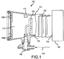
FIG. 1 is a drawing of a partial cross section of a collapsible and inflatable aspirator system, in accordance with various embodiments; -
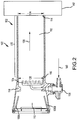
FIG. 2 is a drawing of a cross section of a collapsible and inflatable aspirator system, in accordance with various embodiments; -
FIG. 3 is a drawing of a collapsible and inflatable aspirator system with seams resembling multiple rings, in accordance with various embodiments; -
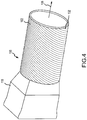
FIG. 4 is a drawing of a collapsible and inflatable aspirator system with seams resembling a helix, in accordance with various embodiments; -
FIG. 5 is a drawing of a cross section of a collapsible and inflatable aspirator system with a diffused opening, in accordance with various embodiments; -
FIG. 6 is a drawing of a collapsible and inflatable aspirator system with seams resembling multiple rings and a diffused opening, in accordance with various embodiments; -
FIG. 7 is a drawing of a collapsible and inflatable aspirator system with seams resembling a helix and a diffused opening, in accordance with various embodiments; and -
FIG. 8 is a block diagram of an airplane with a collapsible and inflatable aspirator system, in accordance with various embodiments. - The detailed description of exemplary embodiments herein makes reference to the accompanying drawings, which show exemplary embodiments by way of illustration and their best mode. While these exemplary embodiments are described in sufficient detail to enable those skilled in the art to practice the disclosure, it should be understood that other embodiments may be realized and that logical, chemical, and mechanical changes may be made without departing from the spirit and scope of the disclosure. Thus, the detailed description herein is presented for purposes of illustration only and not of limitation. For example, the steps recited in any of the method or process descriptions may be executed in any order and are not necessarily limited to the order presented. Furthermore, any reference to singular includes plural embodiments, and any reference to more than one component or step may include a singular embodiment or step. Also, any reference to attached, fixed, connected or the like may include permanent, removable, temporary, partial, full and/or any other possible attachment option. Additionally, any reference to without contact (or similar phrases) may also include reduced contact or minimal contact.
- Aspirators are an important component to an inflatable evacuation system's performance. Aspirators draw atmospheric gas into the inflatable device during inflation to supplement the high-pressure gas provided by the charged gas cylinder. The high-pressure gas entering an aspirator chamber of an aspirator body causes the pressure in the aspirator chamber to fall below atmospheric pressure. As a result, atmospheric gas is drawn into the aspirator chamber and enters the inflatable evacuation device via an aspirator barrel connecting the aspirator body to the inflatable evacuation device.
- Aspirator barrels are rigid despite the low pressure environment within them. Therefore, they may be created from materials such as a metal or reinforced plastic. Being created from rigid materials, aspirators may be bulky and occupy substantial volume. The volume occupied by the aspirator may be an issue when packing inflatable evacuation devices, as aspirators can take up to about 25% or more of the available volume in the inflatable evacuation device pack. More volume occupied by the aspirator leads to higher pack densities and can present issues when manufacturing.
- Turning now to
FIG. 1 , a collapsible andinflatable aspirator system 100 is shown. The collapsible andinflatable aspirator system 100 includes anaspirator body 118, whose cross section is shown, connected to anaspirator barrel 102. Theaspirator barrel 102 is capable of being in an uninflated state (as shown inFIG. 1 ) and also capable of being in an inflated state (as shown inFIG. 2 ). Theaspirator barrel 102 may comprise a flexible fabric. In various embodiments, the flexible fabric is the same type of flexible fabric used in theinflatable evacuation device 142. In various embodiments, the flexible fabric has a high tensile strength and is made of, for example an aramid and/or para-aramid fiber. Being made of a flexible fabric, in an uninflated state, theaspirator barrel 102 is capable of being folded, rolled up, or otherwise compacted. - The
aspirator body 118 includes ashowerhead nozzle 104,flapper doors 106A-106B, and agas valve 108. Theshowerhead nozzle 104 is connected to thegas valve 108. Thegas valve 108 directs high-pressure gas from agas source 140, such as a charged cylinder, through theshowerhead nozzle 104 and into anaspirator chamber 110. Theaspirator chamber 110 is defined by theaspirator body 118. Theaspirator body 118 may be made of a rigid material, such as plastic or metal, in order to protect thegas valve 108, theshowerhead nozzle 104, and theflapper doors 106A-106B, as well as ensuring theaspirator chamber 110 is defined. - When high-pressure gas moves from the
gas source 140 to theaspirator chamber 110 via thegas valve 108 and theshowerhead nozzle 104, atmospheric gas is compelled into theaspirator chamber 110 from outside the collapsible andinflatable aspirator system 100 due to the Venturi effect. The atmospheric gas enters theaspirator chamber 110 throughflapper doors 106A-106B. - The
flapper doors 106A-106B are configured to open inward to allow compelled atmospheric gas to enter theaspirator chamber 110. Theflapper doors 106A-106B are also configured to keep the atmospheric gas from exiting theaspirator chamber 110 via theflapper doors 106A-106B by being a one-way valve. As shown inFIG. 1 , theflapper doors 106A-106B are in a closed configuration, as high-pressure gas is not being provided to theaspirator chamber 110 via thegas valve 108 and theshowerhead nozzle 104. - The
aspirator barrel 102 is connected to theaspirator body 118 at one end, and connected to aninflatable evacuation device 142 at theother end 134. Theaspirator barrel 102 may be connected to the aspirator body by wrapping aband clamp 144 around a flange connection between theaspirator body 118 and theaspirator barrel 102. Theshowerhead nozzle 104 provides the high-pressure gas from thegas source 140 and is connected to theaspirator barrel 102 via aspiratorbarrel inflation connector 116. Theshowerhead nozzle 104 provides a first portion of the high-pressure gas to the aspiratorbarrel inflation connector 116 and provides a second portion of the high-pressure gas to theaspirator chamber 110 to compel atmospheric gas to enter via theflapper doors 106A-106B. In various embodiments, the aspiratorbarrel inflation connector 116 is a flexible tube. In various embodiments, the aspiratorbarrel inflation connector 116 is a rigid pipe. The aspiratorbarrel inflation connector 116 is housed entirely within theaspirator body 118. - Turning now to
FIG. 2 , a cross section of the collapsible andinflatable aspirator system 100 with aninflated aspirator barrel 102 is shown. When thegas valve 108 is opened and high-pressure gas enters theshowerhead nozzle 104, a portion of the high-pressure gas fills theaspirator barrel 102 via the aspiratorbarrel inflation connector 116, and theaspirator barrel 102 inflates. Inflating of theaspirator barrel 102 results in anaspirator barrel chamber 112 being defined by theaspirator barrel 102. - The
aspirator barrel 102 may include a number ofconnected inflation chambers 120. In various embodiments, theaspirator barrel 102 is comprised entirely of theconnected inflation chambers 120. Theconnected inflation chambers 120 may be arranged in different patterns, as shown inFIGS. 3 and4 . However, generally, theconnected inflation chambers 120 are disposed around the circumference of theaspirator barrel 102 and along the length of theaspirator barrel 102. In addition, when viewing a cross section of the collapsible andinflatable aspirator system 100, as shown inFIG. 2 , theconnected inflation chambers 120 generally exhibit a circular pattern aligned along the length of theaspirator barrel 102. Theconnected inflation chambers 120 are connected together via one or more openings to allow gas to pass through from one inflation chamber to another. As a result of being connected, all theconnected inflation chambers 120 are inflated despite the high-pressure gas entering theaspirator barrel 102 at a single location (via aspirator barrel inflation connector 116). In various embodiments, theshowerhead nozzle 104 has multiple aspirator barrel inflation connectors, such that theaspirator barrel 102 is connected to theshowerhead nozzle 104 at many points, allowing for faster inflation of theconnected inflation chambers 120. - The
aspirator barrel 102 includes arelief valve 114. Therelief valve 114 is configured to allow some of the high-pressure gas to enter theaspirator barrel chamber 112. In various embodiments, therelief valve 114 is a one-way valve that opens when the pressure in theconnected inflation chambers 120 of theaspirator barrel 102 exceeds a threshold value. By allowing some of the high-pressure gas to be released, damage to theaspirator barrel 102 from over-inflation of theconnected inflation chambers 120 is reduced or eliminated. Further, by allowing the excess high-pressure gas to enter theaspirator barrel chamber 112 and eventually fill the inflatable device, high-pressure gas is not wasted. - In various embodiments, the
relief valve 114 is simply an opening, such that the high-pressure gas from thegas source 140 travels through theshowerhead nozzle 104, through the aspiratorbarrel inflation connector 116, inflates theconnected inflation chambers 120 of theaspirator barrel 102, travels through theconnected inflation chambers 120, and eventually enters theinflatable evacuation device 142 viaaspirator barrel chamber 112. The respective diameters of therelief valve 114 and the opening of the aspiratorbarrel inflation connector 116 may be tuned in such a way that theaspirator barrel 102 remains inflated with a specified rigidity while the high-pressure gas travels through theconnected inflation chambers 120 of theaspirator barrel 102. - In addition to providing high-pressure gas for inflating the
connected inflation chambers 120 ofaspirator barrel 102, when thegas valve 108 opens and high-pressure gas enters theshowerhead nozzle 104, atmospheric gas enters theaspirator chamber 110 viaflapper doors 106A-106B (in an open state) and atmospheric gas and high-pressure gas is provided in adirection 128 toward theinflatable evacuation device 142, through theaspirator barrel chamber 112 defined by theaspirator barrel 102 in an inflated state. The diameter of the aspiratorbarrel entrance opening 126 is substantially the same as the diameter of the aspiratorbarrel exit opening 124. -
FIG. 3 shows a perspective view of the collapsible andinflatable aspirator system 100 with aninflated aspirator barrel 102. As described herein, theaspirator barrel 102 is connected to theaspirator body 118 and provides atmospheric gas and high-pressure gas in adirection 128 toward the inflatable evacuation device. - The connected inflation chambers 120 (shown in
FIG. 2 ) of theaspirator barrel 102 are connected together to allow gas to pass through from one chamber to the next, but theconnected inflation chambers 120 are also separated byseams 130.Seams 130 follow a pattern such that theconnected inflation chambers 120 of theaspirator barrel 102 are aligned next to each other in a row, along the length of theaspirator barrel 102, with the diameters of theconnected inflation chambers 120 being perpendicular to an axis along the length of theaspirator barrel 102. In various embodiments, theaspirator barrel 102 is created using two sheets of fabric and bonding them together to create theseams 130 and the shape of theaspirator barrel 102. Theseams 130 may be made by bonding a first fabric comprising the outer surface area of theaspirator barrel 102 with a second fabric comprising an inner surface area of theaspirator barrel 102, in lines. The bonding may be achieved by applying an adhesive or by joining the fabric together using heat. -
FIG. 4 shows the collapsible andinflatable aspirator system 100 with aninflated aspirator barrel 102. As described herein, theaspirator barrel 102 is connected to theaspirator body 118 and provides gas in adirection 128 toward the inflatable evacuation device. - The
seams 132 inFIG. 4 follow a swirling or helix pattern, as compared to theseams 130 inFIG. 3 . Having a helix pattern may allow theaspirator barrel 102 to inflate more evenly, as each inflation chamber of theconnected inflation chambers 120 covers more of the surface area of theaspirator barrel 102. -
FIG. 5 shows a cross section of collapsible andinflatable aspirator system 200. The collapsible andinflatable aspirator system 200 has elements in common with collapsible andinflatable aspirator system 100 shown inFIGS. 1-4 , which are numbered similarly. Collapsible andinflatable aspirator system 200 includes anaspirator body 218 which houses ashowerhead nozzle 204, agas valve 208,flapper doors 206A-206B, and aspiratorbarrel inflation connector 216. Theaspirator body 218 defines anaspirator chamber 210, and atmospheric gas and high-pressure gas is provided to theinflatable evacuation device 242 indirection 128. High-pressure gas enters connectedinflation chambers 220 via aspiratorbarrel inflation connector 216. - The cross section of
aspirator barrel 202 illustrates theconnected inflation chambers 220 exhibiting a pattern of round chambers alongside each other along the length of theaspirator barrel 202. In various embodiments, theconnected inflation chambers 220 resemble rings and the diameters of each of theconnected inflation chambers 220 are perpendicular to anaxis 280 along the length of theaspirator barrel 202. Unlike the generally cylindrically shapedaspirator barrel 102 ofFIG. 2 , theaspirator barrel 202 ofFIG. 5 exhibits a shape where the diameter of theaspirator barrel 102 increases as gas travels in thedirection 128 toward the inflatable evacuation device. The shape ofaspirator barrel 202 may generally resemble a frustum. By having the diameter of theaspirator barrel 102 increase as the gas travels indirection 128, diffusion of the atmospheric gas and high-pressure gas is created, achieving improved inflation of the inflatable evacuation device by reducing scavenging effects during inflation when atmospheric gas and high-pressure gas travels quickly throughaspirator barrel chamber 212 indirection 128. -
FIG. 6 shows a perspective view of the collapsible andinflatable aspirator system 200 with aninflated aspirator barrel 202. As described herein, theaspirator barrel 202 is connected to theaspirator body 218 and provides atmospheric gas and high-pressure gas in adirection 128 toward the inflatable evacuation device. - Similar to the
seams 130 ofFIG. 3 ,seams 230 ofFIG. 6 follow a pattern such that the connected inflation chambers 220 (shown inFIG. 5 ) of theaspirator barrel 202 are aligned next to each other in a row, along the length of theaspirator barrel 202, with the diameters of each of theconnected inflation chambers 220 being perpendicular to anaxis 280 along the length of theaspirator barrel 202. -
FIG. 7 shows a perspective view of the collapsible andinflatable aspirator system 200 with aninflated aspirator barrel 202. As described herein, theaspirator barrel 202 is connected to theaspirator body 218 and provides atmospheric gas and high-pressure gas in adirection 128 toward the inflatable evacuation device. - Similar to the
seams 132 ofFIG. 4 , theseams 232 inFIG. 7 follow a swirling or helix pattern, as compared to theseams 230 inFIG. 6 . Having a helix pattern may allow theaspirator barrel 202 to inflate more evenly, as each inflation chamber of theconnected inflation chambers 220 covers more of the surface area of theaspirator barrel 202. -
FIG. 8 is a diagram of a system using the collapsible and inflatable aspirator system. The system includes anairplane 800. Theairplane 800 has anevacuation device package 802. In various embodiments, theevacuation device package 802 is tightly packed to minimize space in the fuselage of theairplane 800. - The
evacuation device package 802 includes anaspirator 804. In various embodiments, theaspirator 804 is a collapsible and inflatable aspirator system similar to collapsible andinflatable aspirator system 100 and collapsible andinflatable aspirator system 200. Theaspirator 804 is connected to agas source 808. In various embodiments, thegas source 808 is a charged gas cylinder. Theaspirator 804 is also connected to anevacuation device 806. In various embodiments, theevacuation device 806 is an inflatable evacuation device, as described herein. - In various embodiments, in an emergency evacuation situation, the
airplane 800 deploys theevacuation device 806. In various embodiments, deploying theevacuation device 806 includes opening theevacuation device package 802 and configuringgas source 808 to provide high-pressure gas toaspirator 804. In turn, theaspirator 804, using the high-pressure gas and atmospheric gas, inflates theevacuation device 806. In various embodiments, theevacuation device 806 is an inflatable slide that passengers may use to exit theairplane 800 in a controlled manner. In various embodiments, theevacuation device 806 is an inflatable raft that passengers may occupy in an emergency situation. - Benefits, other advantages, and solutions to problems have been described herein with regard to specific embodiments. Furthermore, the connecting lines shown in the various figures contained herein are intended to represent exemplary functional relationships and/or physical couplings between the various elements. It should be noted that many alternative or additional functional relationships or physical connections may be present in a practical system. However, the benefits, advantages, solutions to problems, and any elements that may cause any benefit, advantage, or solution to occur or become more pronounced are not to be construed as critical, required, or essential features or elements of the disclosure. The scope of the disclosure is accordingly to be limited by nothing other than the appended claims, in which reference to an element in the singular is not intended to mean "one and only one" unless explicitly so stated, but rather "one or more." Moreover, where a phrase similar to "at least one of A, B, or C" is used in the claims, it is intended that the phrase be interpreted to mean that A alone may be present in an embodiment, B alone may be present in an embodiment, C alone may be present in an embodiment, or that any combination of the elements A, B and C may be present in a single embodiment; for example, A and B, A and C, B and C, or A and B and C. Different cross-hatching is used throughout the figures to denote different parts but not necessarily to denote the same or different materials.
- Systems, methods and apparatus are provided herein. In the detailed description herein, references to "one embodiment", "an embodiment", "an example embodiment", etc., indicate that the embodiment described may include a particular feature, structure, or characteristic, but every embodiment may not necessarily include the particular feature, structure, or characteristic. Moreover, such phrases are not necessarily referring to the same embodiment. Further, when a particular feature, structure, or characteristic is described in connection with an embodiment, it is submitted that it is within the knowledge of one skilled in the art to affect such feature, structure, or characteristic in connection with other embodiments whether or not explicitly described. After reading the description, it will be apparent to one skilled in the relevant art(s) how to implement the disclosure in alternative embodiments.
- Furthermore, no element, component, or method step in the present disclosure is intended to be dedicated to the public regardless of whether the element, component, or method step is explicitly recited in the claims. No claim element herein is to be construed under the provisions of 35 U.S.C. 112, sixth paragraph, unless the element is expressly recited using the phrase "means for." As used herein, the terms "comprises", "comprising", or any other variation thereof, are intended to cover a non-exclusive inclusion, such that a process, method, article, or apparatus that comprises a list of elements does not include only those elements but may include other elements not expressly listed or inherent to such process, method, article, or apparatus.
Claims (15)
- An aspirator system (100; 200; 804) for inflating an inflatable evacuation device (142; 806), the aspirator system comprising:an aspirator body (118; 218) having a plurality of flapper doors (106A - 106B; 206A - 206B) configured to open to allow intake of atmospheric gas;an aspirator barrel (102; 202) connecting the aspirator body (118; 218) to the inflatable evacuation device (146; 806), having connected inflation chambers (120; 220) wrapping around a circumference of the aspirator barrel (102; 202) and arranged along a length of the aspirator barrel (102; 202), and being configured to provide an aspirator barrel chamber (112; 212) for guiding the atmospheric gas to the inflatable evacuation device (142; 806) in response to the aspirator barrel (102; 202) being inflated; anda showerhead nozzle (104; 204) disposed within the aspirator body (118; 218), connected to the connected inflation chambers (120; 220), configured to direct a first portion of high-pressure gas to the connected inflation chambers (120; 220) to inflate the aspirator barrel (102; 202), and configured to direct a second portion of high-pressure gas through the aspirator barrel (102; 202) and compel intake of atmospheric gas through the plurality of flapper doors (106A - 106B; 206A - 206B), to inflate the inflatable evacuation device (142; 806).
- The aspirator system (100; 200; 804) of claim 1, wherein the aspirator barrel (102; 202) is configured to be compacted when not in an inflated state.
- The aspirator system (100; 200; 804) of claim 1 or 2, wherein the aspirator barrel (102; 202) comprises a relief valve (114) configured to release gas into the aspirator barrel chamber (112; 212) in response to a pressure inside the connected inflation chambers (120; 220) exceeding a threshold pressure.
- The aspirator system (100; 200; 804) of any preceding claim, wherein the connected inflation chambers (120; 220) are separated by a plurality of seams (130; 132; 230; 232).
- The aspirator system (100; 200; 804) of claim 4, wherein a shape of the plurality of seams (130; 230) resembles rings arranged along the length of the aspirator barrel (102; 202).
- The aspirator system (100; 200; 804) of claim 4, wherein a shape of the plurality of seams (132; 232) resembles a helix along the length of the aspirator barrel (102; 202).
- An aspirator barrel (102; 202) of an aspirator system (100; 200; 804), the aspirator barrel comprising:connected inflation chambers (120; 220) wrapping around a circumference of the aspirator barrel (102; 202) and arranged along a length of the aspirator barrel, the connected inflation chambers (120; 220) connected to a showerhead nozzle (104; 204) configured to direct high-pressure gas to the connected inflation chambers (120; 220) such that the aspirator barrel (102; 202) is inflated;an aspirator barrel chamber (112; 212) for guiding atmospheric gas from a first end of the aspirator barrel (102; 202) to a second end (134), the aspirator barrel chamber (112; 212) defined by the aspirator barrel (102; 202) in response to the aspirator barrel being inflated; anda relief valve (114) configured to release high-pressure gas out of the aspirator barrel chamber (112; 212) when a pressure inside the connected inflation chambers (120; 220) exceeds a threshold pressure.
- The aspirator system (100; 200; 804) or the aspirator barrel (102; 202) of any preceding claim, wherein the aspirator barrel (102; 202) is made of a flexible fabric.
- The aspirator system (100; 200; 804) or the aspirator barrel (102; 202) of any preceding claim, wherein the showerhead nozzle (104; 204) is connected to the connected inflation chambers (120; 220) at a single point.
- The aspirator system (100; 200; 804) or the aspirator barrel (102; 202) of any of claims 1 to 8, wherein the showerhead nozzle (104; 204) is connected to the connected inflation chambers (120; 220) at a plurality of points.
- The aspirator system (100; 200; 804) or the aspirator barrel (102; 202) of any preceding claim, wherein the aspirator barrel (102; 202) is generally cylindrically shaped.
- The aspirator barrel (102; 202) of any of claims 7 to 11, wherein a diameter of the aspirator barrel (102; 202) at the first end is smaller than a diameter of the aspirator barrel at the second end.
- An airplane (800) comprising:an inflatable evacuation device (806) configured to be inflated when deployed;a charged gas cylinder configured to provide high-pressure gas for inflating the inflatable evacuation device (806); andan aspirator system (804) as claimed in any of claims 1 to 6 or 8 to 11,wherein the showerhead nozzle is configured to direct the first portion of the high-pressure gas from the charged gas cylinder to the connected inflation chambers to inflate the aspirator barrel, and configured to direct the second portion of the high-pressure gas from the charged gas cylinder through the aspirator barrel.
- The aspirator system (100; 200; 804) of any of claims 1 to 6 or 8 to 11 or the airplane (800) of claim 13, wherein the aspirator barrel (102; 202) comprises a first end connected to the aspirator body (118; 218) and a second end connected to the inflatable evacuation device (142; 806), and wherein a diameter of the aspirator barrel (102; 202) at the first end is smaller than a diameter of the aspirator barrel at the second end.
- The airplane (800) of claim 13 or 14, wherein the connected inflation chambers (120; 220) are separated by a plurality of seams (132; 232) resembling a helix along the length of the aspirator barrel (102; 202).
Applications Claiming Priority (1)
| Application Number | Priority Date | Filing Date | Title |
|---|---|---|---|
| US15/130,758 US10167087B2 (en) | 2016-04-15 | 2016-04-15 | Collapsible inflatable aspirator system |
Publications (2)
| Publication Number | Publication Date |
|---|---|
| EP3242040A1 true EP3242040A1 (en) | 2017-11-08 |
| EP3242040B1 EP3242040B1 (en) | 2018-12-12 |
Family
ID=58464259
Family Applications (1)
| Application Number | Title | Priority Date | Filing Date |
|---|---|---|---|
| EP17163658.2A Active EP3242040B1 (en) | 2016-04-15 | 2017-03-29 | Collapsible inflatable aspirator system |
Country Status (2)
| Country | Link |
|---|---|
| US (2) | US10167087B2 (en) |
| EP (1) | EP3242040B1 (en) |
Families Citing this family (11)
| Publication number | Priority date | Publication date | Assignee | Title |
|---|---|---|---|---|
| US10683095B2 (en) * | 2016-12-02 | 2020-06-16 | Goodrich Corporation | Collapsible aspirator barrel |
| US11333174B2 (en) * | 2017-07-06 | 2022-05-17 | Altevac, Llc | High efficiency aspirator for inflatable emergency slides |
| CN107651200A (en) * | 2017-10-30 | 2018-02-02 | 航宇救生装备有限公司 | A kind of multiinjector injector for the inflation of civil aircraft slide |
| US10718356B2 (en) * | 2018-02-12 | 2020-07-21 | Goodrich Corporation | Aspirator inflatable diffuser |
| US10704568B2 (en) | 2018-02-15 | 2020-07-07 | Goodrich Corporation | Aspirator integrated pressure relief valve and vent valve assembly for an inflation system |
| US10876644B2 (en) * | 2018-05-22 | 2020-12-29 | Goodrich Corporation | Aspirator system pressure relief mechanism |
| US10823300B2 (en) * | 2018-10-18 | 2020-11-03 | Goodrich Corporation | Aspirator pressure relief valve with relief control unit |
| US11198514B2 (en) * | 2019-08-19 | 2021-12-14 | Goodrich Corporation | Aspirator with pressure relief flaps |
| US11560905B2 (en) | 2019-12-13 | 2023-01-24 | Goodrich Corporation | Multistage aspirator for inflatable assemblies |
| CN112482910A (en) * | 2020-12-11 | 2021-03-12 | 乾亨贸易(杭州)有限公司 | Inflatable buckle door stopper |
| US12340703B2 (en) | 2021-08-11 | 2025-06-24 | Rosemount Aerospace Inc. | Aircraft door camera system for jet bridge alignment monitoring |
Citations (2)
| Publication number | Priority date | Publication date | Assignee | Title |
|---|---|---|---|---|
| EP0046275A1 (en) * | 1980-08-15 | 1982-02-24 | The B.F. GOODRICH Company | Aspirator for inflating flexible products |
| WO1983002981A1 (en) * | 1982-02-23 | 1983-09-01 | Gen Pneumatics Corp | Fluid apparatus and methods, as for inflating inflatable structures |
Family Cites Families (21)
| Publication number | Priority date | Publication date | Assignee | Title |
|---|---|---|---|---|
| US3370784A (en) * | 1966-02-14 | 1968-02-27 | Ind Covers Inc | Inflation aspirator |
| US3468472A (en) * | 1967-09-15 | 1969-09-23 | Global Systems | Flow augmented nozzle |
| US3460746A (en) * | 1967-10-27 | 1969-08-12 | Rocket Research Corp | Two-stage inflation aspirator |
| US3591314A (en) * | 1969-02-28 | 1971-07-06 | Ind Covers Inc | Aspirator apparatus for bag-inflation system |
| US3572974A (en) * | 1969-04-04 | 1971-03-30 | Sargent Industries | Aspirator apparatus for bag inflation systems |
| US3606586A (en) * | 1969-07-14 | 1971-09-20 | Futurecraft Corp | Air injection pump |
| US3640645A (en) * | 1969-08-28 | 1972-02-08 | Rocket Research Corp | Method and apparatus for aspirating fluids |
| US3684404A (en) * | 1971-03-16 | 1972-08-15 | Rocket Research Corp | Inflating apparatus |
| US3791764A (en) * | 1972-03-01 | 1974-02-12 | Garrett Corp | Variable area ratio jet pump |
| USRE27860E (en) * | 1972-03-13 | 1974-01-01 | Aspirator apparatus for bag inflation systems | |
| US3904324A (en) * | 1972-11-06 | 1975-09-09 | Tech Dev Inc | Tip turbine inflating device |
| US3860984A (en) | 1973-06-25 | 1975-01-21 | Goodrich Co B F | Inflatable life raft escape slide |
| US4566862A (en) * | 1982-02-23 | 1986-01-28 | General Pneumatics Corporation | Fluid apparatus and methods, as for inflating inflatable structures |
| US5002465A (en) * | 1989-10-12 | 1991-03-26 | The Boeing Company | Off-on control for an inflation aspirator |
| US6071084A (en) * | 1995-11-14 | 2000-06-06 | Wass; Lloyd G. | Aspirator |
| US6004176A (en) * | 1998-04-21 | 1999-12-21 | Air Cruisers Company | Aspirator assembly |
| US6199676B1 (en) * | 1999-04-06 | 2001-03-13 | Air Cruisers Company | Inflatable tubular structure with spiral seam |
| US8066493B2 (en) * | 2009-04-16 | 2011-11-29 | Goodrich Corporation | Inflation aspirator with collapsible barrel |
| US9011195B2 (en) | 2011-12-23 | 2015-04-21 | Maximum Visibility Solutions, Llc | Collapsible balloon cup with attachable inflation air tube |
| JP6445281B2 (en) * | 2014-09-01 | 2018-12-26 | 克敏 吉房 | Gas cushion material |
| US9863442B2 (en) * | 2015-07-17 | 2018-01-09 | Goodrich Corporation | Collapsible/extendable aspirator system |
-
2016
- 2016-04-15 US US15/130,758 patent/US10167087B2/en active Active
-
2017
- 2017-03-29 EP EP17163658.2A patent/EP3242040B1/en active Active
-
2018
- 2018-11-27 US US16/201,400 patent/US10780986B2/en active Active
Patent Citations (2)
| Publication number | Priority date | Publication date | Assignee | Title |
|---|---|---|---|---|
| EP0046275A1 (en) * | 1980-08-15 | 1982-02-24 | The B.F. GOODRICH Company | Aspirator for inflating flexible products |
| WO1983002981A1 (en) * | 1982-02-23 | 1983-09-01 | Gen Pneumatics Corp | Fluid apparatus and methods, as for inflating inflatable structures |
Also Published As
| Publication number | Publication date |
|---|---|
| BR102017004851A2 (en) | 2017-10-24 |
| US10780986B2 (en) | 2020-09-22 |
| US20170297726A1 (en) | 2017-10-19 |
| US20190092483A1 (en) | 2019-03-28 |
| US10167087B2 (en) | 2019-01-01 |
| EP3242040B1 (en) | 2018-12-12 |
Similar Documents
| Publication | Publication Date | Title |
|---|---|---|
| US10780986B2 (en) | Collapsible inflatable aspirator system | |
| CN107826258B (en) | Inflatable evacuation system with canopy support | |
| CN106347680A (en) | Collapsible/ extendable aspirator system | |
| US9643707B1 (en) | Fill port for a balloon | |
| EP3348481B1 (en) | Secondary release arrangement for evacuation slide systems | |
| CN107344624B (en) | System and method for retaining removable panels when deploying an evacuation system | |
| CN104208830B (en) | Modularized inflatable unfolding emergency life saving passage | |
| US10676197B2 (en) | Aspirator | |
| US20150161857A1 (en) | Emergency location device | |
| EP3348484B1 (en) | Aspirator system | |
| US20190329850A1 (en) | Compartment ballast system | |
| US20190091704A1 (en) | Telescoping aspirator system | |
| EP3348485B1 (en) | Continuously restrained evacuation system | |
| CN108146640B (en) | System for inflating a flotation device, aircraft with an evacuation system and evacuation system | |
| BR102017004851B1 (en) | VACUUM CLEANER SYSTEM FOR INFLATING AN INFLATABLE EVACUATION DEVICE, VACUUM DRUM OF A VACUUM CLEANER SYSTEM, AND, AIRCRAFT | |
| US10654574B2 (en) | Airfoil for steadying an evacuation slide | |
| CN104724289A (en) | Landing buffer seat with multiple layers of internal and external air bags |
Legal Events
| Date | Code | Title | Description |
|---|---|---|---|
| PUAI | Public reference made under article 153(3) epc to a published international application that has entered the european phase |
Free format text: ORIGINAL CODE: 0009012 |
|
| STAA | Information on the status of an ep patent application or granted ep patent |
Free format text: STATUS: THE APPLICATION HAS BEEN PUBLISHED |
|
| AK | Designated contracting states |
Kind code of ref document: A1 Designated state(s): AL AT BE BG CH CY CZ DE DK EE ES FI FR GB GR HR HU IE IS IT LI LT LU LV MC MK MT NL NO PL PT RO RS SE SI SK SM TR |
|
| AX | Request for extension of the european patent |
Extension state: BA ME |
|
| STAA | Information on the status of an ep patent application or granted ep patent |
Free format text: STATUS: REQUEST FOR EXAMINATION WAS MADE |
|
| 17P | Request for examination filed |
Effective date: 20180501 |
|
| RBV | Designated contracting states (corrected) |
Designated state(s): AL AT BE BG CH CY CZ DE DK EE ES FI FR GB GR HR HU IE IS IT LI LT LU LV MC MK MT NL NO PL PT RO RS SE SI SK SM TR |
|
| GRAP | Despatch of communication of intention to grant a patent |
Free format text: ORIGINAL CODE: EPIDOSNIGR1 |
|
| STAA | Information on the status of an ep patent application or granted ep patent |
Free format text: STATUS: GRANT OF PATENT IS INTENDED |
|
| INTG | Intention to grant announced |
Effective date: 20180620 |
|
| GRAS | Grant fee paid |
Free format text: ORIGINAL CODE: EPIDOSNIGR3 |
|
| GRAA | (expected) grant |
Free format text: ORIGINAL CODE: 0009210 |
|
| STAA | Information on the status of an ep patent application or granted ep patent |
Free format text: STATUS: THE PATENT HAS BEEN GRANTED |
|
| AK | Designated contracting states |
Kind code of ref document: B1 Designated state(s): AL AT BE BG CH CY CZ DE DK EE ES FI FR GB GR HR HU IE IS IT LI LT LU LV MC MK MT NL NO PL PT RO RS SE SI SK SM TR |
|
| REG | Reference to a national code |
Ref country code: GB Ref legal event code: FG4D |
|
| REG | Reference to a national code |
Ref country code: CH Ref legal event code: EP |
|
| REG | Reference to a national code |
Ref country code: AT Ref legal event code: REF Ref document number: 1076395 Country of ref document: AT Kind code of ref document: T Effective date: 20181215 |
|
| REG | Reference to a national code |
Ref country code: DE Ref legal event code: R096 Ref document number: 602017001283 Country of ref document: DE |
|
| REG | Reference to a national code |
Ref country code: IE Ref legal event code: FG4D |
|
| REG | Reference to a national code |
Ref country code: NL Ref legal event code: MP Effective date: 20181212 |
|
| REG | Reference to a national code |
Ref country code: LT Ref legal event code: MG4D |
|
| PG25 | Lapsed in a contracting state [announced via postgrant information from national office to epo] |
Ref country code: ES Free format text: LAPSE BECAUSE OF FAILURE TO SUBMIT A TRANSLATION OF THE DESCRIPTION OR TO PAY THE FEE WITHIN THE PRESCRIBED TIME-LIMIT Effective date: 20181212 Ref country code: LT Free format text: LAPSE BECAUSE OF FAILURE TO SUBMIT A TRANSLATION OF THE DESCRIPTION OR TO PAY THE FEE WITHIN THE PRESCRIBED TIME-LIMIT Effective date: 20181212 Ref country code: NO Free format text: LAPSE BECAUSE OF FAILURE TO SUBMIT A TRANSLATION OF THE DESCRIPTION OR TO PAY THE FEE WITHIN THE PRESCRIBED TIME-LIMIT Effective date: 20190312 Ref country code: FI Free format text: LAPSE BECAUSE OF FAILURE TO SUBMIT A TRANSLATION OF THE DESCRIPTION OR TO PAY THE FEE WITHIN THE PRESCRIBED TIME-LIMIT Effective date: 20181212 Ref country code: BG Free format text: LAPSE BECAUSE OF FAILURE TO SUBMIT A TRANSLATION OF THE DESCRIPTION OR TO PAY THE FEE WITHIN THE PRESCRIBED TIME-LIMIT Effective date: 20190312 Ref country code: HR Free format text: LAPSE BECAUSE OF FAILURE TO SUBMIT A TRANSLATION OF THE DESCRIPTION OR TO PAY THE FEE WITHIN THE PRESCRIBED TIME-LIMIT Effective date: 20181212 Ref country code: LV Free format text: LAPSE BECAUSE OF FAILURE TO SUBMIT A TRANSLATION OF THE DESCRIPTION OR TO PAY THE FEE WITHIN THE PRESCRIBED TIME-LIMIT Effective date: 20181212 |
|
| REG | Reference to a national code |
Ref country code: AT Ref legal event code: MK05 Ref document number: 1076395 Country of ref document: AT Kind code of ref document: T Effective date: 20181212 |
|
| PG25 | Lapsed in a contracting state [announced via postgrant information from national office to epo] |
Ref country code: RS Free format text: LAPSE BECAUSE OF FAILURE TO SUBMIT A TRANSLATION OF THE DESCRIPTION OR TO PAY THE FEE WITHIN THE PRESCRIBED TIME-LIMIT Effective date: 20181212 Ref country code: AL Free format text: LAPSE BECAUSE OF FAILURE TO SUBMIT A TRANSLATION OF THE DESCRIPTION OR TO PAY THE FEE WITHIN THE PRESCRIBED TIME-LIMIT Effective date: 20181212 Ref country code: SE Free format text: LAPSE BECAUSE OF FAILURE TO SUBMIT A TRANSLATION OF THE DESCRIPTION OR TO PAY THE FEE WITHIN THE PRESCRIBED TIME-LIMIT Effective date: 20181212 Ref country code: GR Free format text: LAPSE BECAUSE OF FAILURE TO SUBMIT A TRANSLATION OF THE DESCRIPTION OR TO PAY THE FEE WITHIN THE PRESCRIBED TIME-LIMIT Effective date: 20190313 |
|
| PG25 | Lapsed in a contracting state [announced via postgrant information from national office to epo] |
Ref country code: NL Free format text: LAPSE BECAUSE OF FAILURE TO SUBMIT A TRANSLATION OF THE DESCRIPTION OR TO PAY THE FEE WITHIN THE PRESCRIBED TIME-LIMIT Effective date: 20181212 |
|
| PG25 | Lapsed in a contracting state [announced via postgrant information from national office to epo] |
Ref country code: PL Free format text: LAPSE BECAUSE OF FAILURE TO SUBMIT A TRANSLATION OF THE DESCRIPTION OR TO PAY THE FEE WITHIN THE PRESCRIBED TIME-LIMIT Effective date: 20181212 Ref country code: IT Free format text: LAPSE BECAUSE OF FAILURE TO SUBMIT A TRANSLATION OF THE DESCRIPTION OR TO PAY THE FEE WITHIN THE PRESCRIBED TIME-LIMIT Effective date: 20181212 Ref country code: PT Free format text: LAPSE BECAUSE OF FAILURE TO SUBMIT A TRANSLATION OF THE DESCRIPTION OR TO PAY THE FEE WITHIN THE PRESCRIBED TIME-LIMIT Effective date: 20190412 Ref country code: CZ Free format text: LAPSE BECAUSE OF FAILURE TO SUBMIT A TRANSLATION OF THE DESCRIPTION OR TO PAY THE FEE WITHIN THE PRESCRIBED TIME-LIMIT Effective date: 20181212 |
|
| PG25 | Lapsed in a contracting state [announced via postgrant information from national office to epo] |
Ref country code: RO Free format text: LAPSE BECAUSE OF FAILURE TO SUBMIT A TRANSLATION OF THE DESCRIPTION OR TO PAY THE FEE WITHIN THE PRESCRIBED TIME-LIMIT Effective date: 20181212 Ref country code: SM Free format text: LAPSE BECAUSE OF FAILURE TO SUBMIT A TRANSLATION OF THE DESCRIPTION OR TO PAY THE FEE WITHIN THE PRESCRIBED TIME-LIMIT Effective date: 20181212 Ref country code: EE Free format text: LAPSE BECAUSE OF FAILURE TO SUBMIT A TRANSLATION OF THE DESCRIPTION OR TO PAY THE FEE WITHIN THE PRESCRIBED TIME-LIMIT Effective date: 20181212 Ref country code: IS Free format text: LAPSE BECAUSE OF FAILURE TO SUBMIT A TRANSLATION OF THE DESCRIPTION OR TO PAY THE FEE WITHIN THE PRESCRIBED TIME-LIMIT Effective date: 20190412 Ref country code: SK Free format text: LAPSE BECAUSE OF FAILURE TO SUBMIT A TRANSLATION OF THE DESCRIPTION OR TO PAY THE FEE WITHIN THE PRESCRIBED TIME-LIMIT Effective date: 20181212 |
|
| REG | Reference to a national code |
Ref country code: DE Ref legal event code: R097 Ref document number: 602017001283 Country of ref document: DE |
|
| PLBE | No opposition filed within time limit |
Free format text: ORIGINAL CODE: 0009261 |
|
| STAA | Information on the status of an ep patent application or granted ep patent |
Free format text: STATUS: NO OPPOSITION FILED WITHIN TIME LIMIT |
|
| PG25 | Lapsed in a contracting state [announced via postgrant information from national office to epo] |
Ref country code: SI Free format text: LAPSE BECAUSE OF FAILURE TO SUBMIT A TRANSLATION OF THE DESCRIPTION OR TO PAY THE FEE WITHIN THE PRESCRIBED TIME-LIMIT Effective date: 20181212 Ref country code: DK Free format text: LAPSE BECAUSE OF FAILURE TO SUBMIT A TRANSLATION OF THE DESCRIPTION OR TO PAY THE FEE WITHIN THE PRESCRIBED TIME-LIMIT Effective date: 20181212 Ref country code: AT Free format text: LAPSE BECAUSE OF FAILURE TO SUBMIT A TRANSLATION OF THE DESCRIPTION OR TO PAY THE FEE WITHIN THE PRESCRIBED TIME-LIMIT Effective date: 20181212 Ref country code: MC Free format text: LAPSE BECAUSE OF FAILURE TO SUBMIT A TRANSLATION OF THE DESCRIPTION OR TO PAY THE FEE WITHIN THE PRESCRIBED TIME-LIMIT Effective date: 20181212 |
|
| 26N | No opposition filed |
Effective date: 20190913 |
|
| PG25 | Lapsed in a contracting state [announced via postgrant information from national office to epo] |
Ref country code: LU Free format text: LAPSE BECAUSE OF NON-PAYMENT OF DUE FEES Effective date: 20190329 |
|
| REG | Reference to a national code |
Ref country code: BE Ref legal event code: MM Effective date: 20190331 |
|
| PG25 | Lapsed in a contracting state [announced via postgrant information from national office to epo] |
Ref country code: IE Free format text: LAPSE BECAUSE OF NON-PAYMENT OF DUE FEES Effective date: 20190329 |
|
| PG25 | Lapsed in a contracting state [announced via postgrant information from national office to epo] |
Ref country code: BE Free format text: LAPSE BECAUSE OF NON-PAYMENT OF DUE FEES Effective date: 20190331 |
|
| PG25 | Lapsed in a contracting state [announced via postgrant information from national office to epo] |
Ref country code: TR Free format text: LAPSE BECAUSE OF FAILURE TO SUBMIT A TRANSLATION OF THE DESCRIPTION OR TO PAY THE FEE WITHIN THE PRESCRIBED TIME-LIMIT Effective date: 20181212 |
|
| PG25 | Lapsed in a contracting state [announced via postgrant information from national office to epo] |
Ref country code: MT Free format text: LAPSE BECAUSE OF NON-PAYMENT OF DUE FEES Effective date: 20190329 |
|
| REG | Reference to a national code |
Ref country code: CH Ref legal event code: PL |
|
| PG25 | Lapsed in a contracting state [announced via postgrant information from national office to epo] |
Ref country code: LI Free format text: LAPSE BECAUSE OF NON-PAYMENT OF DUE FEES Effective date: 20200331 Ref country code: CH Free format text: LAPSE BECAUSE OF NON-PAYMENT OF DUE FEES Effective date: 20200331 |
|
| PG25 | Lapsed in a contracting state [announced via postgrant information from national office to epo] |
Ref country code: CY Free format text: LAPSE BECAUSE OF FAILURE TO SUBMIT A TRANSLATION OF THE DESCRIPTION OR TO PAY THE FEE WITHIN THE PRESCRIBED TIME-LIMIT Effective date: 20181212 |
|
| PG25 | Lapsed in a contracting state [announced via postgrant information from national office to epo] |
Ref country code: HU Free format text: LAPSE BECAUSE OF FAILURE TO SUBMIT A TRANSLATION OF THE DESCRIPTION OR TO PAY THE FEE WITHIN THE PRESCRIBED TIME-LIMIT; INVALID AB INITIO Effective date: 20170329 |
|
| GBPC | Gb: european patent ceased through non-payment of renewal fee |
Effective date: 20210329 |
|
| PG25 | Lapsed in a contracting state [announced via postgrant information from national office to epo] |
Ref country code: GB Free format text: LAPSE BECAUSE OF NON-PAYMENT OF DUE FEES Effective date: 20210329 |
|
| PG25 | Lapsed in a contracting state [announced via postgrant information from national office to epo] |
Ref country code: MK Free format text: LAPSE BECAUSE OF FAILURE TO SUBMIT A TRANSLATION OF THE DESCRIPTION OR TO PAY THE FEE WITHIN THE PRESCRIBED TIME-LIMIT Effective date: 20181212 |
|
| P01 | Opt-out of the competence of the unified patent court (upc) registered |
Effective date: 20230522 |
|
| PGFP | Annual fee paid to national office [announced via postgrant information from national office to epo] |
Ref country code: DE Payment date: 20260219 Year of fee payment: 10 |
|
| PGFP | Annual fee paid to national office [announced via postgrant information from national office to epo] |
Ref country code: FR Payment date: 20260220 Year of fee payment: 10 |