EP3241718A1 - Trailing module for a switch machine and switch machine - Google Patents
Trailing module for a switch machine and switch machine Download PDFInfo
- Publication number
- EP3241718A1 EP3241718A1 EP16305526.2A EP16305526A EP3241718A1 EP 3241718 A1 EP3241718 A1 EP 3241718A1 EP 16305526 A EP16305526 A EP 16305526A EP 3241718 A1 EP3241718 A1 EP 3241718A1
- Authority
- EP
- European Patent Office
- Prior art keywords
- trailing
- sliding area
- module
- linear actuator
- switch machine
- Prior art date
- Legal status (The legal status is an assumption and is not a legal conclusion. Google has not performed a legal analysis and makes no representation as to the accuracy of the status listed.)
- Granted
Links
- 230000007246 mechanism Effects 0.000 claims abstract description 32
- 230000006641 stabilisation Effects 0.000 claims description 19
- 238000011105 stabilization Methods 0.000 claims description 19
- 238000006073 displacement reaction Methods 0.000 description 6
- 230000006378 damage Effects 0.000 description 2
- 230000001419 dependent effect Effects 0.000 description 1
- 230000037431 insertion Effects 0.000 description 1
- 238000003780 insertion Methods 0.000 description 1
- 210000000056 organ Anatomy 0.000 description 1
- 238000009420 retrofitting Methods 0.000 description 1
- 230000000087 stabilizing effect Effects 0.000 description 1
Images


Classifications
-
- B—PERFORMING OPERATIONS; TRANSPORTING
- B61—RAILWAYS
- B61L—GUIDING RAILWAY TRAFFIC; ENSURING THE SAFETY OF RAILWAY TRAFFIC
- B61L5/00—Local operating mechanisms for points or track-mounted scotch-blocks; Visible or audible signals; Local operating mechanisms for visible or audible signals
- B61L5/02—Mechanical devices for operating points or scotch-blocks, e.g. local manual control
Definitions
- the present invention relates to a trailing module for a switch machine of a railway switch.
- the present invention concerns a switch machine for a railway switch.
- WO 2004/074066 A1 relates to a switch machine for a railway switch.
- the switch machine is modular.
- the architecture does not allow for the addition of new modules at a later time.
- Object of the invention is to provide a trailing module and a switch machine, which allow an easy way to provide a trailing module into the switch machine.
- a trailing module for a switch machine of a railway switch having two blades connected to a driving bar comprising a linear actuator adapted to linearly move between a first position and the second position
- the trailing module comprising: a first member, and a second member, wherein the first member being movably connected to the second member via at least one trailing mechanism, each trailing mechanism comprising at least one linear sliding area at the first member, a biasing device arranged between the second member and an intermediate member adapted to push the intermediate member away from the second member in a trailing direction in parallel to the movement direction of the linear actuator, wherein the intermediate member comprises at least one slider adapted to slide on the sliding area and which is biased against the sliding area, wherein the sliding area has a first portion with a first distance and a second portion with a second distance with respect to the second member, wherein the second distance is closer to the second member than the first distance, wherein the trailing mechanism has as first operation mode and a second operation mode, wherein in
- a switch machine for a railway switch a railway switch having two blades connected to a driving bar, the switch machine comprising: a driving chain adapted to displacing the driving bar of the switch between two positions, wherein the driving chain comprises a linear actuator adapted to linearly move between a first position and a second position; and a housing adapted to receive a trailing module according to an embodiment disclosed herein, wherein the trailing module is adapted to be rigidly connected to the linear actuator and to the driving bar.
- Figure 1 and 2 show a switch machine 1.
- the switch machine has housing 3 in the form and the dimensions of a railroad tie.
- the housing 3 has the form of a channel.
- the switch machine 1 can be placed on the track like a tie.
- the switch machine 1 comprises a linear actuator 5 or motorized driving means for displacing blades (not shown) of a switch between two opposite position.
- the blades of the switch may be rigidly connected to the connection devices 7 of a driving bar 8.
- the switch machine 1, in particular the driving bar 8 comprises a stroke limitation module 9.
- the stroke limitation module 9 is provided in a central part of the switch machine to enable a limited movement of one blade to the other, in order to avoid a destruction of locking modules 11.
- the stroke limitation module 9 is provided for induced blade displacements due to mechanical stresses which are caused by a trailing action allowing compensate for displacements having limited strokes.
- the open blade will be able to move without pulling the closed blade locking module.
- the switch machine 1 includes a driving shaft 13.
- the driving shaft 13 is driven by the linear actuator 5 and can be driven in a linear direction back and forth between a first position and a second position.
- Trailing is called the possibility that a railway vehicle moves with its wheels the switch from one position to another position, for example if the train traverses the switch in a direction in which two tracks converge to one track.
- the wheels of the railway vehicle exercise a force on the blades by pushing the blades from a current position against the opposite rail.
- the driving bar 8 of the open and closed blade can be directly and rigidly connected, for example via a fix stroke module (not shown) in place of the stroke limitation module 9.
- the switch is not designed for trailing.
- the driving shaft 13 is connected to the linear actuator 5 through a fix element (not shown) and is linked to the blades and/or the driving bar 8 by means of hammers contained in the locking modules (not shown).
- the interface of the driving shaft 13 and the linear actuator 5 are adapted to be connected to a trailing module 16 and/or a stabilization module 17 instead of being directly connected to each other.
- the switch machine further comprises the trailing module 16 and/or the stabilization module 17.
- the trailing module 16 is rigidly connected to the driving shaft 13 and the linear actuator 5.
- the stabilization module 17 is also rigidly connected to the linear actuator 5, for example via the trailing module 16.
- the trailing module 16 may be mounted into the switch, in particular a driving chain of the switch comprising also the linear actuator 5, the driving shaft 13 and the driving bar 8, in case trailability is desired.
- the trailing module 16 allows releasing or freeing the blades, the driving shaft 13 and the driving bar 8 from the remaining driving chain such as the linear actuator 5 to avoiding damages since the blades are free to be displaced.
- Figure 3 shows a cross section through the trailing module 16.
- the trailing module comprises a first member 19, which is arranged within a second member 21.
- the first member 19 and the second member 21 are movable with respect to each other, in a direction parallel to the stroke of the blades or the movement direction of the driving shaft 13 and/or the driving bar 8.
- the second member 21 may guide the relative movement of the first member 19.
- the first member 19 has a bar shape.
- the second member 21 has also an elongated shape.
- the first member 19 is rigidly connected to the linear actuator 5. For example they are connected via a bold or a screw connection.
- the second member 21 is rigidly connected to the driving shaft 13, which is connected to driving bar 8 through the hammers (not shown) contained in the locking module.
- the driving bar 8 may include the stroke limitation module 9.
- a first end 23 of the second member 21 extending in direction of the linear actuator 5 extends between the connection point 14 of the linear actuator 5 and the connection point 15 of the driving shaft 13.
- the first end 23 of the second member 21 is rigidly connected to the connection point 15 of the driving bar 8.
- the first member 19 has a first end 25 and a second end 27 in the movement direction of the driving shaft 13.
- the first end 25 is rigidly connected to the connection point 14 of the linear actuator 5.
- the second end 27 is adapted to be connected to the stabilization module 17 as it will be explained later.
- the first end 25 of the first member 19 is connected to the linear actuator 5 below the connection between the first end 23 of the second member 21 and the connection point 15 of the driving shaft 13.
- the first member 19 and the second member are mechanically linked by at least one trailing mechanism 30a, 30b, which allows the first and/or second member 19, 21 free to move with respect to each other only if a predetermined force is exerted.
- the predetermined force corresponds to a predetermined distance the second member 21 is moved with respect to the first member 19 in a trailing direction being parallel to the movement direction of the driving shaft 13, the driving bar 8 and/or the linear actuator 5.
- first trailing mechanism 30a has a trailing direction in direction of the arrow 32a and the second trailing mechanism 30b has a trailing direction in direction of the arrow 32b.
- Each trailing mechanism 30a, 30b comprises a linear sliding area 34a, 34b on the first member 19.
- the linear sliding area extends in the trailing direction 32a, 32b.
- Each sliding area 34a, 34b has a first portion 36a, 36b with a first distance d1 and a second portion 38a, 38b with a second distance d2 with respect to the second member 21, wherein the second distance d2 is closer to the second member 21 than the first distance d1.
- the first portion 36a, 36b of the sliding area may be realized as a groove.
- a step is arranged between the first portion 36a, 36b and the second portion 38a, 38b of the sliding area 34a, 34b.
- the first portion 36a, 36b of the sliding area 34a, 34b has a length in opposite direction of the trailing direction 32a, 32b corresponding to the length of the trailing movement of the respective other trailing mechanism 30a, 30b.
- the length of the first portion 36a of the sliding area 34a of the first trailing mechanism 30a corresponds to the maximal lengths of the trailing movement of the second trailing mechanism 30b and vice versa.
- the first portion 36a, 36b of the sliding area 34a, 34b has substantially the same lengths in trailing direction 32a, 32b as the second portion 38a, 38b of the sliding area 34a, 34b.
- the sliding area 34a of the first trailing mechanism 30a is arranged on the opposite side of the first member 19 with respect to the sliding area 34b of the second trailing mechanism 30b.
- the sliding area 34a of the first trailing mechanism 30a is arranged on the upper side of the first member 19 and the sliding area 34b of the second trailing mechanism 30b is arranged on the lower side of the first member 19.
- each trailing mechanism 30a, 30b includes a biasing device 40a, 40b, for example a first spring, in particular a helical spring, arranged between the second member 21 and the intermediate member 42a, 42b adapted to push the intermediate member 42a, 42b away from the second member 21 in a trailing direction 32a, 32b.
- the first member 19 includes for each biasing device 40a, 40b a supporting surface 44a, 44b in the trailing direction to support the respective biasing devices 40a, 40b.
- the biasing device 40a, 40b partially surrounds the first member 19.
- the intermediate members 42a, 42b are adapted to move with respect to the first member 19 and the second member 21.
- the intermediate members 42a, 42b may surround the first member 19 and/or are arranged within the second member 21, so that they can only perform a guided movement.
- the intermediate members 42a, 42b may move in specifically arranged guides of the first and/or second member 19, 21.
- Each intermediate member 42a, 42b comprises at least one slider 46a, 46b adapted to slide on the sliding area 34a, 34b and which is biased against the sliding area 34a, 34b.
- the slider 46a, 46b may be biased against the sliding area by a second spring (not shown).
- the slider 46a, 46b are movable in a direction orthogonal to the trailing direction.
- the slider 46a, 46b are movable in a vertical direction.
- the slider 46a, 46b may either slide or engage the first portion 36a, 36b of the sliding area 34a, 34b, or the slider 46a, 46b may slide on the second portion 38a, 38b of the sliding area 34a, 34b.
- the slider may have a slightly rounded surface for better moving over the step in the sliding area 34a, 34b.
- the predetermined force depends on the spring constants of first spring 40a, 40b and/or the second spring
- Each trailing mechanism 30a, 30b has as first operation mode and a second operation mode.
- the first operation mode the slider is engaged in the first portion 36a, 36b of the sliding area 34a, 34b.
- the second member is prevented to move in the trailing direction 32a, 32b, beyond the step between the first portion 36a, 36b and the second portion 38a, 38b of the sliding area 34a, 34b.
- the biasing member 40a, 40b of one of the trailing mechanism may be already compressed so that the second member 21 already moves into the trailing direction 32a, 32b of one of the trailing mechanism.
- the slider of one of the trailing mechanism is disengaged from the first portion 36a, 36b of the sliding area 34a, 34b by moving towards the second member 21 against the force of the second spring and slides on the second portion 38a, 38b of the sliding area 34a, 34b.
- the second member 21 is moved in the trailing direction.
- the slider 46a is not any more engaged by the step between the first and second portions 36a, 38a, but moves, in Figure 2 , upwards towards the intermediate and the second member 21, 42a, so that it can slide on the second portion 38a.
- the slider 46b of the second trailing mechanism 30b slides in the trailing direction 32a of the first trailing mechanism 30a within the first portion 36b of the sliding area 34b of the second trailing mechanism 30b.
- FIG 4 shows schematically a cross section of the stabilization module 17.
- the stabilization module 17 has the task of avoiding that the trailing mechanism will be activated if a force lower than a certain value is exerted on the blades. Further, the stabilization module 17 defines two positions, in particular of the linear actuator 5, namely a first position and a second position. The two positions are stable if a certain force is not exceeded.
- the stabilization module has a housing 50 which may be fixed to the housing 3 of the switch machine 1 and a moving member 52, which is rigidly connected to the linear actuator 5.
- the moving member 52 is rigidly connected to the first member 19 of the trailing module 16. The moving member 52 is guided within the housing 50 by the means of guides 56.
- the housing is provided with at least two recesses or notches 54 at two positions defining the first and second position.
- the moving member 52 is provided with at least, in particular two opposite rolls 58. Instead of rolls other sliding means 58 may be used.
- the rolls 58 are biased against the housing 50, for example with a third spring 60.
- the spring biases the two opposite rolls 58 against two opposite walls of the housing 50 and/or the guides 56.
- the recesses are provided in the lateral walls of the housing along which the rolls 58 moves. If the third biasing means or spring 60 pushes the rolls in the notches a non-permanent lock of the moving member 52 is obtained.
- Force needed to unlock the moving member 52 from the recesses 54 is set in such a way that when the linear actuator 5 has enough power to overcome the stabilization force thus allowing the displacement of the moving member 52 and the driving of the blades.
- the moving member 52 When mechanical stresses are transmitted to the blades determining small displacements and/or less mechanical forces on the driving organs the moving member 52 will not be unlocked. In this case the trailing module 16 compensates this small displacement and the first member 19 remains locked in the current end of stroke position corresponding to the current position of the blades.
- the stabilization module compensates displacements of lesser stroke which the blades might suffer due to mechanical stresses not caused by a trailing action. This avoids that in this case the trailing module 16 is activated and the mechanical connection between blades and driving chain is lost.
- a rigid connection is a connection wherein the connected parts do not move with respect to each other.
- a rigid connection is a screw connection, a soldered connection, or a bold connection.
- the connected parts may move with respect to each other.
- the driving bar 8 and the driving shaft 13 may be directly connected to each other for a non-trailable configuration even if the trailing module 15 is present in the housing, in case a trailing function is not needed in the railway switch.
- the trailing function may be dynamically enabled and disabled by short circuiting or adding modules in the driving chain of the switch.
- mechanical interfaces are provided in the driving chain of the blades which allow insertion of optional units allowing the switch machine to be trailed.
- the dimensions of a tie are maintained, in particular in a way to comply with the prescribed security levels.
Landscapes
- Engineering & Computer Science (AREA)
- Mechanical Engineering (AREA)
- Train Traffic Observation, Control, And Security (AREA)
Abstract
Description
- The present invention relates to a trailing module for a switch machine of a railway switch.
- Further, the present invention concerns a switch machine for a railway switch.
-
WO 2004/074066 A1 relates to a switch machine for a railway switch. The switch machine is modular. However, the architecture does not allow for the addition of new modules at a later time. - Object of the invention is to provide a trailing module and a switch machine, which allow an easy way to provide a trailing module into the switch machine.
- According to one aspect, a trailing module for a switch machine of a railway switch having two blades connected to a driving bar is provided, the switch machine comprising a linear actuator adapted to linearly move between a first position and the second position, the trailing module comprising: a first member, and a second member, wherein the first member being movably connected to the second member via at least one trailing mechanism, each trailing mechanism comprising at least one linear sliding area at the first member, a biasing device arranged between the second member and an intermediate member adapted to push the intermediate member away from the second member in a trailing direction in parallel to the movement direction of the linear actuator, wherein the intermediate member comprises at least one slider adapted to slide on the sliding area and which is biased against the sliding area, wherein the sliding area has a first portion with a first distance and a second portion with a second distance with respect to the second member, wherein the second distance is closer to the second member than the first distance, wherein the trailing mechanism has as first operation mode and a second operation mode, wherein in the first operation mode, the slider is engaged in the first portion of the sliding area, and in the second operation mode, when the second member is moved with respect to the first member in the trailing direction a predetermined distance, the slider is disengaged from the first portion of the sliding area and slides on the second portion of the sliding area, wherein a first one of the first member and the second member being adapted to be rigidly connected to the linear actuator, and a second one of the first member and the second member being adapted to be connected to the driving bar..
- Further embodiments may relate to one or more of the following features, which may be combined in any technical feasible combination:
- the second portion is disposed after the first portion in the trailing direction;
- each linear sliding area extends in trailing direction;
- the first member is arranged inside the second member;
- the intermediate member comprises a second biasing device, for example a spring, to press the slider against the sliding area;
- the slider is rotatably fixed to the intermediate member; and/or
- the trailing module comprises two trailing mechanisms having opposite trailing directions.
- According to another aspect, a switch machine is provided for a railway switch a railway switch having two blades connected to a driving bar, the switch machine comprising: a driving chain adapted to displacing the driving bar of the switch between two positions, wherein the driving chain comprises a linear actuator adapted to linearly move between a first position and a second position; and a housing adapted to receive a trailing module according to an embodiment disclosed herein, wherein the trailing module is adapted to be rigidly connected to the linear actuator and to the driving bar.
- Further embodiments may relate to one or more of the following features, which may be combined in any technical feasible combination:
- the housing is further adapted to receive a stabilization module, wherein the stabilization module is rigidly connected to the linear actuator, wherein the stabilization module is adapted to releasably lock the linear actuator either in the first position or the second position.
- the stabilization module is adapted to be rigidly connected to the linear actuator via the trailing module; and/or
- the housing has the form of a railroad tie.
- Further advantages, features, aspects and details are evident from the dependent claims, the description and the drawings.
- So that the manner in which the above recited features of the present invention can be understood in detail, a more particular description of the invention, briefly summarized above, may be read by reference to embodiments. The accompanying drawings relate to embodiments of the invention and are described in the following:
-
Fig. 1 is a schematical perspective view of a switch machine; -
Fig. 2 is a schematical perspective view of a switch machine -
Fig. 3 shows a cross section through a trailing module; and -
Fig. 4 shows a cross section through a stabilization module. -
Figure 1 and 2 show a switch machine 1. The switch machine has housing 3 in the form and the dimensions of a railroad tie. For example, the housing 3 has the form of a channel. Thus, the switch machine 1 can be placed on the track like a tie. The switch machine 1 comprises alinear actuator 5 or motorized driving means for displacing blades (not shown) of a switch between two opposite position. For example the blades of the switch may be rigidly connected to theconnection devices 7 of adriving bar 8. - Further, the switch machine 1, in particular the
driving bar 8 comprises astroke limitation module 9. Thestroke limitation module 9 is provided in a central part of the switch machine to enable a limited movement of one blade to the other, in order to avoid a destruction oflocking modules 11. For example, thestroke limitation module 9 is provided for induced blade displacements due to mechanical stresses which are caused by a trailing action allowing compensate for displacements having limited strokes. When the switch machine 1 is subject to a trailing event, the open blade will be able to move without pulling the closed blade locking module. - Further, the switch machine 1 includes a
driving shaft 13. Thedriving shaft 13 is driven by thelinear actuator 5 and can be driven in a linear direction back and forth between a first position and a second position. - Trailing is called the possibility that a railway vehicle moves with its wheels the switch from one position to another position, for example if the train traverses the switch in a direction in which two tracks converge to one track. In other words, the wheels of the railway vehicle exercise a force on the blades by pushing the blades from a current position against the opposite rail.
- In an embodiment, the
driving bar 8 of the open and closed blade can be directly and rigidly connected, for example via a fix stroke module (not shown) in place of thestroke limitation module 9. In this case, the switch is not designed for trailing. In this non-trailable configuration thedriving shaft 13 is connected to thelinear actuator 5 through a fix element (not shown) and is linked to the blades and/or thedriving bar 8 by means of hammers contained in the locking modules (not shown). - According to an embodiment, the interface of the
driving shaft 13 and thelinear actuator 5 are adapted to be connected to atrailing module 16 and/or astabilization module 17 instead of being directly connected to each other. In this embodiment of the invention, the switch machine further comprises thetrailing module 16 and/or thestabilization module 17. Thetrailing module 16 is rigidly connected to thedriving shaft 13 and thelinear actuator 5. According to an embodiment, thestabilization module 17 is also rigidly connected to thelinear actuator 5, for example via thetrailing module 16. For example thetrailing module 16 may be mounted into the switch, in particular a driving chain of the switch comprising also thelinear actuator 5, thedriving shaft 13 and thedriving bar 8, in case trailability is desired. - The
trailing module 16 allows releasing or freeing the blades, thedriving shaft 13 and thedriving bar 8 from the remaining driving chain such as thelinear actuator 5 to avoiding damages since the blades are free to be displaced. -
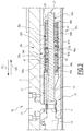
Figure 3 shows a cross section through thetrailing module 16. The trailing module comprises afirst member 19, which is arranged within asecond member 21. Thefirst member 19 and thesecond member 21 are movable with respect to each other, in a direction parallel to the stroke of the blades or the movement direction of thedriving shaft 13 and/or thedriving bar 8. In other words, thesecond member 21 may guide the relative movement of thefirst member 19. Thefirst member 19 has a bar shape. Thesecond member 21 has also an elongated shape. - The
first member 19 is rigidly connected to thelinear actuator 5. For example they are connected via a bold or a screw connection. - The
second member 21 is rigidly connected to thedriving shaft 13, which is connected to drivingbar 8 through the hammers (not shown) contained in the locking module. Thedriving bar 8 may include thestroke limitation module 9. According to an embodiment afirst end 23 of thesecond member 21 extending in direction of thelinear actuator 5 extends between theconnection point 14 of thelinear actuator 5 and theconnection point 15 of thedriving shaft 13. Thefirst end 23 of thesecond member 21 is rigidly connected to theconnection point 15 of thedriving bar 8. - The
first member 19 has afirst end 25 and asecond end 27 in the movement direction of thedriving shaft 13. Thefirst end 25 is rigidly connected to theconnection point 14 of thelinear actuator 5. Thesecond end 27 is adapted to be connected to thestabilization module 17 as it will be explained later. - Thus, according to an embodiment, the
first end 25 of thefirst member 19 is connected to thelinear actuator 5 below the connection between thefirst end 23 of thesecond member 21 and theconnection point 15 of thedriving shaft 13. - The
first member 19 and the second member are mechanically linked by at least onetrailing mechanism second member second member 21 is moved with respect to thefirst member 19 in a trailing direction being parallel to the movement direction of the drivingshaft 13, the drivingbar 8 and/or thelinear actuator 5. - In the embodiment shown in
Figure 3 , two trailingmechanisms first trailing mechanism 30a has a trailing direction in direction of thearrow 32a and thesecond trailing mechanism 30b has a trailing direction in direction of thearrow 32b. - Each trailing
mechanism area first member 19. The linear sliding area extends in the trailingdirection area first portion second portion second member 21, wherein the second distance d2 is closer to thesecond member 21 than the first distance d1. For example thefirst portion first portion second portion area first portion area direction mechanism first portion 36a of the slidingarea 34a of thefirst trailing mechanism 30a corresponds to the maximal lengths of the trailing movement of thesecond trailing mechanism 30b and vice versa. In some embodiments, thefirst portion area direction second portion area - According to some embodiments, the sliding
area 34a of thefirst trailing mechanism 30a is arranged on the opposite side of thefirst member 19 with respect to the slidingarea 34b of thesecond trailing mechanism 30b. For example, infigure 2 , the slidingarea 34a of thefirst trailing mechanism 30a is arranged on the upper side of thefirst member 19 and the slidingarea 34b of thesecond trailing mechanism 30b is arranged on the lower side of thefirst member 19. - Further, the each trailing
mechanism biasing device second member 21 and theintermediate member intermediate member second member 21 in a trailingdirection first member 19 includes for each biasingdevice surface respective biasing devices - In an embodiment, the
biasing device first member 19. - The
intermediate members first member 19 and thesecond member 21. For example, theintermediate members first member 19 and/or are arranged within thesecond member 21, so that they can only perform a guided movement. In another embodiment, theintermediate members second member - Each
intermediate member slider area area slider slider slider slider first portion area slider second portion area area - In some embodiments, the predetermined force depends on the spring constants of
first spring - Each trailing
mechanism first portion area direction first portion second portion area second member 21 in the slidingdirection member second member 21 already moves into the trailingdirection - In the second operation mode, when the
second member 21 is moved with respect to thefirst member 19 in one of the trailingdirections first portion area second member 21 against the force of the second spring and slides on thesecond portion area second member 21 is moved in the trailing direction. If the distance exceeds a predetermined distance and/or a force acting on thesecond member 21 in the trailingdirection 32a exceeds a predetermined force, theslider 46a is not any more engaged by the step between the first andsecond portions Figure 2 , upwards towards the intermediate and thesecond member second portion 38a. During this movement, theslider 46b of thesecond trailing mechanism 30b slides in the trailingdirection 32a of thefirst trailing mechanism 30a within thefirst portion 36b of the slidingarea 34b of thesecond trailing mechanism 30b. -
Figure 4 shows schematically a cross section of thestabilization module 17. Thestabilization module 17 has the task of avoiding that the trailing mechanism will be activated if a force lower than a certain value is exerted on the blades. Further, thestabilization module 17 defines two positions, in particular of thelinear actuator 5, namely a first position and a second position. The two positions are stable if a certain force is not exceeded. For that purpose, the stabilization module has ahousing 50 which may be fixed to the housing 3 of the switch machine 1 and a movingmember 52, which is rigidly connected to thelinear actuator 5. For example, the movingmember 52 is rigidly connected to thefirst member 19 of the trailingmodule 16. The movingmember 52 is guided within thehousing 50 by the means ofguides 56. - The housing is provided with at least two recesses or
notches 54 at two positions defining the first and second position. The movingmember 52 is provided with at least, in particular two opposite rolls 58. Instead of rolls other sliding means 58 may be used. Therolls 58 are biased against thehousing 50, for example with athird spring 60. For example the spring biases the twoopposite rolls 58 against two opposite walls of thehousing 50 and/or theguides 56. The recesses are provided in the lateral walls of the housing along which therolls 58 moves. If the third biasing means orspring 60 pushes the rolls in the notches a non-permanent lock of the movingmember 52 is obtained. - Force needed to unlock the moving
member 52 from therecesses 54 is set in such a way that when thelinear actuator 5 has enough power to overcome the stabilization force thus allowing the displacement of the movingmember 52 and the driving of the blades. - In the case of a trailing action the force needed to overcome the link between
first member 19 and thesecond member 21 of the trailingmodule 16 is not sufficient to unlock the moving member of the stabilizingmodule 17, too. Therefore thefirst member 19 does not move during a trailing action. - When mechanical stresses are transmitted to the blades determining small displacements and/or less mechanical forces on the driving organs the moving
member 52 will not be unlocked. In this case the trailingmodule 16 compensates this small displacement and thefirst member 19 remains locked in the current end of stroke position corresponding to the current position of the blades. - The stabilization module compensates displacements of lesser stroke which the blades might suffer due to mechanical stresses not caused by a trailing action. This avoids that in this case the trailing
module 16 is activated and the mechanical connection between blades and driving chain is lost. - According to the invention, a rigid connection is a connection wherein the connected parts do not move with respect to each other. For example a rigid connection is a screw connection, a soldered connection, or a bold connection. In contrast, in a movable connection, the connected parts may move with respect to each other.
- According to an embodiment, the driving
bar 8 and the drivingshaft 13 may be directly connected to each other for a non-trailable configuration even if the trailingmodule 15 is present in the housing, in case a trailing function is not needed in the railway switch. In other words, the trailing function may be dynamically enabled and disabled by short circuiting or adding modules in the driving chain of the switch. Thus, a user has not to decide from the very beginning which kind of switch machine he needs: trailable or non trailable and has the opportunity to carry out upgrade interventions for adding or eliminating such functions. - According to the invention mechanical interfaces are provided in the driving chain of the blades which allow insertion of optional units allowing the switch machine to be trailed.
- The functions of providing secure end of stroke positions of the actuator and allowing compensation of minor stresses and the trailing function are divided on two simple modules which can be mounted at any time.
- According to the invention it is possible to leave the choice open for the user to operate retrofitting actions on the switch box for implementing further functionalities due to the mounting in a second moment of modular units for carrying out the further functions.
- For example, the dimensions of a tie are maintained, in particular in a way to comply with the prescribed security levels.
Claims (11)
- Trailing module (16) for a switch machine (1) of a railway switch having two blades connected to a driving bar (8), the switch machine comprising a linear actuator (5) adapted to linearly move between a first position and the second position, the trailing module (16) comprising:a first member (19,21), anda second member (19, 21), wherein
the first member (19, 21) being movably connected to the second member (19, 21) via at least one trailing mechanism (30a, 30b), each trailing mechanism comprising at least one linear sliding area (34a, 34b) at the first member, a biasing device (40a, 40b) arranged between the second member (19, 21) and an intermediate member (42a, 42b) adapted to push the intermediate member (42a, 42b) away from the second member in a trailing direction (32a, 32b) in parallel to the movement direction of the linear actuator (5), wherein the intermediate member comprises at least one slider (46a, 46b) adapted to slide on the sliding area and which is biased against the sliding area (34a, 34b), wherein the sliding area has a first portion (36a, 36b) with a first distance (d1) and a second portion (38a, 38b) with a second distance with respect to the second member (19, 21), wherein the second distance (d2) is closer to the second member than the first distance (d1), wherein the trailing mechanism (30a, 30b) has as first operation mode and a second operation mode, wherein in the first operation mode, the slider (46a, 46b) is engaged in the first portion of the sliding area, and in the second operation mode, when the second member (19, 21) is moved with respect to the first member in the trailing direction (32a, 32b) a predetermined distance, the slider is disengaged from the first portion of the sliding area and slides on the second portion (38a, 38b) of the sliding area, wherein a first one of the first member and the second member being adapted to be rigidly connected to the linear actuator (5), and a second one of the first member and the second member being adapted to be connected to the driving bar (8). - Trailing module according to claim 1, wherein the second portion (38a, 38b) is disposed after the first portion (36a, 36b) in the trailing direction.
- Trailing module according to claim 1 or 2, wherein each linear sliding area extends in trailing direction (32a, 32b).
- Trailing module according to one of the preceding claims, wherein the first member (19) is arranged inside the second member (21).
- Trailing module according to one of the preceding claims, wherein the intermediate member comprises a second biasing device, for example a spring, to press the slider (46a, 46b) against the sliding area (34a, 34b).
- Trailing module according to one of the preceding claims, wherein the slider is rotatably fixed to the intermediate member (42a, 42b).
- Trailing module according to one of the preceding claims, comprising two trailing mechanisms (30a, 30b) having opposite trailing directions.
- Switch machine (1) for a railway switch a railway switch having two blades connected to a driving bar (8), the switch machine comprising:a driving chain (5) adapted to displacing the driving bar (8) of the switch between two positions, wherein the driving chain (5) comprises a linear actuator (5) adapted to linearly move between a first position and a second position; anda housing (3) adapted to receive a trailing module (16) according to claim 1, wherein the trailing module is adapted to be rigidly connected to the linear actuator (5) and to the driving bar (8).
- Switch machine for a railway switch according to claim 8, wherein the housing is further adapted to receive a stabilization module (17), wherein the stabilization module is rigidly connected to the linear actuator (5), wherein the stabilization module is adapted to releasably lock the linear actuator (5)either in the first position or the second position.
- Switch machine according to claim 8 or 9, wherein the stabilization module (17) is adapted to be rigidly connected to the linear actuator (5) via the trailing module (16).
- Switch machine according to one of the claims 8 to 10, wherein the housing (3) has the form of a railroad tie.
Priority Applications (2)
| Application Number | Priority Date | Filing Date | Title |
|---|---|---|---|
| EP16305526.2A EP3241718B1 (en) | 2016-05-04 | 2016-05-04 | Trailing module for a switch machine and switch machine |
| DK16305526.2T DK3241718T3 (en) | 2016-05-04 | 2016-05-04 | Tracking module for a switching machine as well as a switching machine |
Applications Claiming Priority (1)
| Application Number | Priority Date | Filing Date | Title |
|---|---|---|---|
| EP16305526.2A EP3241718B1 (en) | 2016-05-04 | 2016-05-04 | Trailing module for a switch machine and switch machine |
Publications (2)
| Publication Number | Publication Date |
|---|---|
| EP3241718A1 true EP3241718A1 (en) | 2017-11-08 |
| EP3241718B1 EP3241718B1 (en) | 2019-07-03 |
Family
ID=55970934
Family Applications (1)
| Application Number | Title | Priority Date | Filing Date |
|---|---|---|---|
| EP16305526.2A Active EP3241718B1 (en) | 2016-05-04 | 2016-05-04 | Trailing module for a switch machine and switch machine |
Country Status (2)
| Country | Link |
|---|---|
| EP (1) | EP3241718B1 (en) |
| DK (1) | DK3241718T3 (en) |
Citations (4)
| Publication number | Priority date | Publication date | Assignee | Title |
|---|---|---|---|---|
| DE3020788A1 (en) * | 1980-05-31 | 1981-12-10 | Standard Elektrik Lorenz Ag, 7000 Stuttgart | INTERNAL LOCKING DEVICE FOR A POINT DRIVE |
| US5590857A (en) * | 1994-08-19 | 1997-01-07 | General Railway Signal Corporation | Trailing device for a railroad switch layout |
| WO2004074066A1 (en) | 2003-02-18 | 2004-09-02 | Alstom Ferroviaria S.P.A | Switch machine for railway and tramway switches or the like |
| US9238474B1 (en) * | 2013-06-20 | 2016-01-19 | Norfolk Southern Corporation | Run-through switch rods |
-
2016
- 2016-05-04 DK DK16305526.2T patent/DK3241718T3/en active
- 2016-05-04 EP EP16305526.2A patent/EP3241718B1/en active Active
Patent Citations (5)
| Publication number | Priority date | Publication date | Assignee | Title |
|---|---|---|---|---|
| DE3020788A1 (en) * | 1980-05-31 | 1981-12-10 | Standard Elektrik Lorenz Ag, 7000 Stuttgart | INTERNAL LOCKING DEVICE FOR A POINT DRIVE |
| US5590857A (en) * | 1994-08-19 | 1997-01-07 | General Railway Signal Corporation | Trailing device for a railroad switch layout |
| WO2004074066A1 (en) | 2003-02-18 | 2004-09-02 | Alstom Ferroviaria S.P.A | Switch machine for railway and tramway switches or the like |
| EP1594732A1 (en) * | 2003-02-18 | 2005-11-16 | Alstom Ferroviaria S.P.A. | Switch machine for railway and tramway switches |
| US9238474B1 (en) * | 2013-06-20 | 2016-01-19 | Norfolk Southern Corporation | Run-through switch rods |
Also Published As
| Publication number | Publication date |
|---|---|
| EP3241718B1 (en) | 2019-07-03 |
| DK3241718T3 (en) | 2019-09-23 |
Similar Documents
| Publication | Publication Date | Title |
|---|---|---|
| CN101798890B (en) | Locking device | |
| KR100421240B1 (en) | Switch box for railway, tramway points, or similar | |
| US10106021B2 (en) | Arrangement comprising a cover for a vehicle roof | |
| US6691958B2 (en) | Switch machine | |
| DE102007034481A1 (en) | Locking device with locking part | |
| EP1690713B1 (en) | System for sliding plug door for a vehicle | |
| RU2005126408A (en) | ARROW DRIVE FOR RAILWAY AND TRAM ARROWS | |
| EP2535238B1 (en) | Railway, tramway or the like turnout of so-called English type | |
| WO2008052506A1 (en) | Sunroof | |
| EP3241718B1 (en) | Trailing module for a switch machine and switch machine | |
| EP1832680B1 (en) | Switch machine with switch point connectors | |
| EP1516983B1 (en) | Lock cylinder | |
| EP3403530B1 (en) | Driving mechanism, protection device and control method applicable to furniture | |
| KR101709440B1 (en) | Movable body driving device | |
| CN101019197B (en) | Accumulator | |
| CN1150100A (en) | Switch with internal locking mechanism | |
| EP0810138B1 (en) | Locking device for railway points | |
| DE102019106627A1 (en) | Safety brake device and safety brake method | |
| DE2935969C2 (en) | Closure for the lid of a container arranged on a chassis of a trolley | |
| EP1623903B1 (en) | Switch lock system | |
| RU2768339C2 (en) | Device for preventing coming off for sliding doors of furniture items | |
| EP3835168A1 (en) | Railway switch machine with adjustable stroke | |
| PL61711Y1 (en) | Slider-type mechanical lock with blocking | |
| CZ11894U1 (en) | Sliding mechanical lock with adjustment of lift | |
| DE411359C (en) | Double tongue switch for hanging railways |
Legal Events
| Date | Code | Title | Description |
|---|---|---|---|
| PUAI | Public reference made under article 153(3) epc to a published international application that has entered the european phase |
Free format text: ORIGINAL CODE: 0009012 |
|
| STAA | Information on the status of an ep patent application or granted ep patent |
Free format text: STATUS: THE APPLICATION HAS BEEN PUBLISHED |
|
| STAA | Information on the status of an ep patent application or granted ep patent |
Free format text: STATUS: REQUEST FOR EXAMINATION WAS MADE |
|
| AK | Designated contracting states |
Kind code of ref document: A1 Designated state(s): AL AT BE BG CH CY CZ DE DK EE ES FI FR GB GR HR HU IE IS IT LI LT LU LV MC MK MT NL NO PL PT RO RS SE SI SK SM TR |
|
| AX | Request for extension of the european patent |
Extension state: BA ME |
|
| 17P | Request for examination filed |
Effective date: 20171018 |
|
| RBV | Designated contracting states (corrected) |
Designated state(s): AL AT BE BG CH CY CZ DE DK EE ES FI FR GB GR HR HU IE IS IT LI LT LU LV MC MK MT NL NO PL PT RO RS SE SI SK SM TR |
|
| GRAP | Despatch of communication of intention to grant a patent |
Free format text: ORIGINAL CODE: EPIDOSNIGR1 |
|
| STAA | Information on the status of an ep patent application or granted ep patent |
Free format text: STATUS: GRANT OF PATENT IS INTENDED |
|
| INTG | Intention to grant announced |
Effective date: 20181130 |
|
| GRAJ | Information related to disapproval of communication of intention to grant by the applicant or resumption of examination proceedings by the epo deleted |
Free format text: ORIGINAL CODE: EPIDOSDIGR1 |
|
| STAA | Information on the status of an ep patent application or granted ep patent |
Free format text: STATUS: REQUEST FOR EXAMINATION WAS MADE |
|
| GRAR | Information related to intention to grant a patent recorded |
Free format text: ORIGINAL CODE: EPIDOSNIGR71 |
|
| GRAS | Grant fee paid |
Free format text: ORIGINAL CODE: EPIDOSNIGR3 |
|
| STAA | Information on the status of an ep patent application or granted ep patent |
Free format text: STATUS: GRANT OF PATENT IS INTENDED |
|
| INTC | Intention to grant announced (deleted) | ||
| INTG | Intention to grant announced |
Effective date: 20190412 |
|
| GRAA | (expected) grant |
Free format text: ORIGINAL CODE: 0009210 |
|
| STAA | Information on the status of an ep patent application or granted ep patent |
Free format text: STATUS: THE PATENT HAS BEEN GRANTED |
|
| AK | Designated contracting states |
Kind code of ref document: B1 Designated state(s): AL AT BE BG CH CY CZ DE DK EE ES FI FR GB GR HR HU IE IS IT LI LT LU LV MC MK MT NL NO PL PT RO RS SE SI SK SM TR |
|
| REG | Reference to a national code |
Ref country code: GB Ref legal event code: FG4D |
|
| REG | Reference to a national code |
Ref country code: CH Ref legal event code: EP Ref country code: AT Ref legal event code: REF Ref document number: 1150629 Country of ref document: AT Kind code of ref document: T Effective date: 20190715 |
|
| REG | Reference to a national code |
Ref country code: IE Ref legal event code: FG4D |
|
| REG | Reference to a national code |
Ref country code: DE Ref legal event code: R096 Ref document number: 602016016233 Country of ref document: DE |
|
| REG | Reference to a national code |
Ref country code: DK Ref legal event code: T3 Effective date: 20190919 |
|
| REG | Reference to a national code |
Ref country code: SE Ref legal event code: TRGR |
|
| REG | Reference to a national code |
Ref country code: NL Ref legal event code: FP |
|
| REG | Reference to a national code |
Ref country code: NO Ref legal event code: T2 Effective date: 20190703 |
|
| REG | Reference to a national code |
Ref country code: LT Ref legal event code: MG4D |
|
| REG | Reference to a national code |
Ref country code: AT Ref legal event code: MK05 Ref document number: 1150629 Country of ref document: AT Kind code of ref document: T Effective date: 20190703 |
|
| PG25 | Lapsed in a contracting state [announced via postgrant information from national office to epo] |
Ref country code: CZ Free format text: LAPSE BECAUSE OF FAILURE TO SUBMIT A TRANSLATION OF THE DESCRIPTION OR TO PAY THE FEE WITHIN THE PRESCRIBED TIME-LIMIT Effective date: 20190703 Ref country code: FI Free format text: LAPSE BECAUSE OF FAILURE TO SUBMIT A TRANSLATION OF THE DESCRIPTION OR TO PAY THE FEE WITHIN THE PRESCRIBED TIME-LIMIT Effective date: 20190703 Ref country code: HR Free format text: LAPSE BECAUSE OF FAILURE TO SUBMIT A TRANSLATION OF THE DESCRIPTION OR TO PAY THE FEE WITHIN THE PRESCRIBED TIME-LIMIT Effective date: 20190703 Ref country code: AT Free format text: LAPSE BECAUSE OF FAILURE TO SUBMIT A TRANSLATION OF THE DESCRIPTION OR TO PAY THE FEE WITHIN THE PRESCRIBED TIME-LIMIT Effective date: 20190703 Ref country code: PT Free format text: LAPSE BECAUSE OF FAILURE TO SUBMIT A TRANSLATION OF THE DESCRIPTION OR TO PAY THE FEE WITHIN THE PRESCRIBED TIME-LIMIT Effective date: 20191104 Ref country code: LT Free format text: LAPSE BECAUSE OF FAILURE TO SUBMIT A TRANSLATION OF THE DESCRIPTION OR TO PAY THE FEE WITHIN THE PRESCRIBED TIME-LIMIT Effective date: 20190703 Ref country code: BG Free format text: LAPSE BECAUSE OF FAILURE TO SUBMIT A TRANSLATION OF THE DESCRIPTION OR TO PAY THE FEE WITHIN THE PRESCRIBED TIME-LIMIT Effective date: 20191003 |
|
| PG25 | Lapsed in a contracting state [announced via postgrant information from national office to epo] |
Ref country code: AL Free format text: LAPSE BECAUSE OF FAILURE TO SUBMIT A TRANSLATION OF THE DESCRIPTION OR TO PAY THE FEE WITHIN THE PRESCRIBED TIME-LIMIT Effective date: 20190703 Ref country code: ES Free format text: LAPSE BECAUSE OF FAILURE TO SUBMIT A TRANSLATION OF THE DESCRIPTION OR TO PAY THE FEE WITHIN THE PRESCRIBED TIME-LIMIT Effective date: 20190703 Ref country code: RS Free format text: LAPSE BECAUSE OF FAILURE TO SUBMIT A TRANSLATION OF THE DESCRIPTION OR TO PAY THE FEE WITHIN THE PRESCRIBED TIME-LIMIT Effective date: 20190703 Ref country code: LV Free format text: LAPSE BECAUSE OF FAILURE TO SUBMIT A TRANSLATION OF THE DESCRIPTION OR TO PAY THE FEE WITHIN THE PRESCRIBED TIME-LIMIT Effective date: 20190703 Ref country code: GR Free format text: LAPSE BECAUSE OF FAILURE TO SUBMIT A TRANSLATION OF THE DESCRIPTION OR TO PAY THE FEE WITHIN THE PRESCRIBED TIME-LIMIT Effective date: 20191004 Ref country code: IS Free format text: LAPSE BECAUSE OF FAILURE TO SUBMIT A TRANSLATION OF THE DESCRIPTION OR TO PAY THE FEE WITHIN THE PRESCRIBED TIME-LIMIT Effective date: 20191103 |
|
| PG25 | Lapsed in a contracting state [announced via postgrant information from national office to epo] |
Ref country code: TR Free format text: LAPSE BECAUSE OF FAILURE TO SUBMIT A TRANSLATION OF THE DESCRIPTION OR TO PAY THE FEE WITHIN THE PRESCRIBED TIME-LIMIT Effective date: 20190703 |
|
| PG25 | Lapsed in a contracting state [announced via postgrant information from national office to epo] |
Ref country code: RO Free format text: LAPSE BECAUSE OF FAILURE TO SUBMIT A TRANSLATION OF THE DESCRIPTION OR TO PAY THE FEE WITHIN THE PRESCRIBED TIME-LIMIT Effective date: 20190703 Ref country code: IT Free format text: LAPSE BECAUSE OF FAILURE TO SUBMIT A TRANSLATION OF THE DESCRIPTION OR TO PAY THE FEE WITHIN THE PRESCRIBED TIME-LIMIT Effective date: 20190703 Ref country code: PL Free format text: LAPSE BECAUSE OF FAILURE TO SUBMIT A TRANSLATION OF THE DESCRIPTION OR TO PAY THE FEE WITHIN THE PRESCRIBED TIME-LIMIT Effective date: 20190703 Ref country code: EE Free format text: LAPSE BECAUSE OF FAILURE TO SUBMIT A TRANSLATION OF THE DESCRIPTION OR TO PAY THE FEE WITHIN THE PRESCRIBED TIME-LIMIT Effective date: 20190703 |
|
| PG25 | Lapsed in a contracting state [announced via postgrant information from national office to epo] |
Ref country code: SK Free format text: LAPSE BECAUSE OF FAILURE TO SUBMIT A TRANSLATION OF THE DESCRIPTION OR TO PAY THE FEE WITHIN THE PRESCRIBED TIME-LIMIT Effective date: 20190703 Ref country code: IS Free format text: LAPSE BECAUSE OF FAILURE TO SUBMIT A TRANSLATION OF THE DESCRIPTION OR TO PAY THE FEE WITHIN THE PRESCRIBED TIME-LIMIT Effective date: 20200224 Ref country code: SM Free format text: LAPSE BECAUSE OF FAILURE TO SUBMIT A TRANSLATION OF THE DESCRIPTION OR TO PAY THE FEE WITHIN THE PRESCRIBED TIME-LIMIT Effective date: 20190703 |
|
| REG | Reference to a national code |
Ref country code: DE Ref legal event code: R097 Ref document number: 602016016233 Country of ref document: DE |
|
| PLBE | No opposition filed within time limit |
Free format text: ORIGINAL CODE: 0009261 |
|
| STAA | Information on the status of an ep patent application or granted ep patent |
Free format text: STATUS: NO OPPOSITION FILED WITHIN TIME LIMIT |
|
| PG2D | Information on lapse in contracting state deleted |
Ref country code: IS |
|
| 26N | No opposition filed |
Effective date: 20200603 |
|
| PG25 | Lapsed in a contracting state [announced via postgrant information from national office to epo] |
Ref country code: SI Free format text: LAPSE BECAUSE OF FAILURE TO SUBMIT A TRANSLATION OF THE DESCRIPTION OR TO PAY THE FEE WITHIN THE PRESCRIBED TIME-LIMIT Effective date: 20190703 |
|
| REG | Reference to a national code |
Ref country code: DE Ref legal event code: R119 Ref document number: 602016016233 Country of ref document: DE |
|
| PG25 | Lapsed in a contracting state [announced via postgrant information from national office to epo] |
Ref country code: MC Free format text: LAPSE BECAUSE OF FAILURE TO SUBMIT A TRANSLATION OF THE DESCRIPTION OR TO PAY THE FEE WITHIN THE PRESCRIBED TIME-LIMIT Effective date: 20190703 Ref country code: LI Free format text: LAPSE BECAUSE OF NON-PAYMENT OF DUE FEES Effective date: 20200531 Ref country code: CH Free format text: LAPSE BECAUSE OF NON-PAYMENT OF DUE FEES Effective date: 20200531 |
|
| REG | Reference to a national code |
Ref country code: BE Ref legal event code: MM Effective date: 20200531 |
|
| GBPC | Gb: european patent ceased through non-payment of renewal fee |
Effective date: 20200504 |
|
| PG25 | Lapsed in a contracting state [announced via postgrant information from national office to epo] |
Ref country code: LU Free format text: LAPSE BECAUSE OF NON-PAYMENT OF DUE FEES Effective date: 20200504 |
|
| PG25 | Lapsed in a contracting state [announced via postgrant information from national office to epo] |
Ref country code: GB Free format text: LAPSE BECAUSE OF NON-PAYMENT OF DUE FEES Effective date: 20200504 Ref country code: IE Free format text: LAPSE BECAUSE OF NON-PAYMENT OF DUE FEES Effective date: 20200504 Ref country code: FR Free format text: LAPSE BECAUSE OF NON-PAYMENT OF DUE FEES Effective date: 20200531 |
|
| PG25 | Lapsed in a contracting state [announced via postgrant information from national office to epo] |
Ref country code: DE Free format text: LAPSE BECAUSE OF NON-PAYMENT OF DUE FEES Effective date: 20201201 Ref country code: BE Free format text: LAPSE BECAUSE OF NON-PAYMENT OF DUE FEES Effective date: 20200531 |
|
| PGFP | Annual fee paid to national office [announced via postgrant information from national office to epo] |
Ref country code: NO Payment date: 20210521 Year of fee payment: 6 Ref country code: NL Payment date: 20210519 Year of fee payment: 6 |
|
| PGFP | Annual fee paid to national office [announced via postgrant information from national office to epo] |
Ref country code: DK Payment date: 20210521 Year of fee payment: 6 Ref country code: SE Payment date: 20210519 Year of fee payment: 6 |
|
| PG25 | Lapsed in a contracting state [announced via postgrant information from national office to epo] |
Ref country code: MT Free format text: LAPSE BECAUSE OF FAILURE TO SUBMIT A TRANSLATION OF THE DESCRIPTION OR TO PAY THE FEE WITHIN THE PRESCRIBED TIME-LIMIT Effective date: 20190703 Ref country code: CY Free format text: LAPSE BECAUSE OF FAILURE TO SUBMIT A TRANSLATION OF THE DESCRIPTION OR TO PAY THE FEE WITHIN THE PRESCRIBED TIME-LIMIT Effective date: 20190703 |
|
| PG25 | Lapsed in a contracting state [announced via postgrant information from national office to epo] |
Ref country code: MK Free format text: LAPSE BECAUSE OF FAILURE TO SUBMIT A TRANSLATION OF THE DESCRIPTION OR TO PAY THE FEE WITHIN THE PRESCRIBED TIME-LIMIT Effective date: 20190703 |
|
| REG | Reference to a national code |
Ref country code: DK Ref legal event code: EBP Effective date: 20220531 |
|
| REG | Reference to a national code |
Ref country code: NO Ref legal event code: MMEP |
|
| REG | Reference to a national code |
Ref country code: SE Ref legal event code: EUG |
|
| REG | Reference to a national code |
Ref country code: NL Ref legal event code: MM Effective date: 20220601 |
|
| PG25 | Lapsed in a contracting state [announced via postgrant information from national office to epo] |
Ref country code: SE Free format text: LAPSE BECAUSE OF NON-PAYMENT OF DUE FEES Effective date: 20220505 Ref country code: NO Free format text: LAPSE BECAUSE OF NON-PAYMENT OF DUE FEES Effective date: 20220531 |
|
| PG25 | Lapsed in a contracting state [announced via postgrant information from national office to epo] |
Ref country code: DK Free format text: LAPSE BECAUSE OF NON-PAYMENT OF DUE FEES Effective date: 20220531 |
|
| PG25 | Lapsed in a contracting state [announced via postgrant information from national office to epo] |
Ref country code: NL Free format text: LAPSE BECAUSE OF NON-PAYMENT OF DUE FEES Effective date: 20220601 |