EP3241626A1 - Rolling mill comprising a mandrel of improved type, and related mandrel and method of operation - Google Patents
Rolling mill comprising a mandrel of improved type, and related mandrel and method of operation Download PDFInfo
- Publication number
- EP3241626A1 EP3241626A1 EP17164513.8A EP17164513A EP3241626A1 EP 3241626 A1 EP3241626 A1 EP 3241626A1 EP 17164513 A EP17164513 A EP 17164513A EP 3241626 A1 EP3241626 A1 EP 3241626A1
- Authority
- EP
- European Patent Office
- Prior art keywords
- strip
- mandrel
- cylinder
- slot
- grip
- Prior art date
- Legal status (The legal status is an assumption and is not a legal conclusion. Google has not performed a legal analysis and makes no representation as to the accuracy of the status listed.)
- Granted
Links
Images


Classifications
-
- B—PERFORMING OPERATIONS; TRANSPORTING
- B21—MECHANICAL METAL-WORKING WITHOUT ESSENTIALLY REMOVING MATERIAL; PUNCHING METAL
- B21C—MANUFACTURE OF METAL SHEETS, WIRE, RODS, TUBES, PROFILES OR LIKE SEMI-MANUFACTURED PRODUCTS OTHERWISE THAN BY ROLLING; AUXILIARY OPERATIONS USED IN CONNECTION WITH METAL-WORKING WITHOUT ESSENTIALLY REMOVING MATERIAL
- B21C47/00—Winding-up, coiling or winding-off metal wire, metal band or other flexible metal material characterised by features relevant to metal processing only
- B21C47/32—Tongs or gripping means specially adapted for reeling operations
- B21C47/323—Slits or pinces on the cylindrical wall of a reel or bobbin, adapted to grip the end of the material being wound
-
- B—PERFORMING OPERATIONS; TRANSPORTING
- B21—MECHANICAL METAL-WORKING WITHOUT ESSENTIALLY REMOVING MATERIAL; PUNCHING METAL
- B21C—MANUFACTURE OF METAL SHEETS, WIRE, RODS, TUBES, PROFILES OR LIKE SEMI-MANUFACTURED PRODUCTS OTHERWISE THAN BY ROLLING; AUXILIARY OPERATIONS USED IN CONNECTION WITH METAL-WORKING WITHOUT ESSENTIALLY REMOVING MATERIAL
- B21C47/00—Winding-up, coiling or winding-off metal wire, metal band or other flexible metal material characterised by features relevant to metal processing only
- B21C47/28—Drums or other coil-holders
- B21C47/30—Drums or other coil-holders expansible or contractible
-
- B—PERFORMING OPERATIONS; TRANSPORTING
- B21—MECHANICAL METAL-WORKING WITHOUT ESSENTIALLY REMOVING MATERIAL; PUNCHING METAL
- B21C—MANUFACTURE OF METAL SHEETS, WIRE, RODS, TUBES, PROFILES OR LIKE SEMI-MANUFACTURED PRODUCTS OTHERWISE THAN BY ROLLING; AUXILIARY OPERATIONS USED IN CONNECTION WITH METAL-WORKING WITHOUT ESSENTIALLY REMOVING MATERIAL
- B21C47/00—Winding-up, coiling or winding-off metal wire, metal band or other flexible metal material characterised by features relevant to metal processing only
- B21C47/02—Winding-up or coiling
- B21C47/04—Winding-up or coiling on or in reels or drums, without using a moving guide
-
- B—PERFORMING OPERATIONS; TRANSPORTING
- B21—MECHANICAL METAL-WORKING WITHOUT ESSENTIALLY REMOVING MATERIAL; PUNCHING METAL
- B21C—MANUFACTURE OF METAL SHEETS, WIRE, RODS, TUBES, PROFILES OR LIKE SEMI-MANUFACTURED PRODUCTS OTHERWISE THAN BY ROLLING; AUXILIARY OPERATIONS USED IN CONNECTION WITH METAL-WORKING WITHOUT ESSENTIALLY REMOVING MATERIAL
- B21C47/00—Winding-up, coiling or winding-off metal wire, metal band or other flexible metal material characterised by features relevant to metal processing only
- B21C47/16—Unwinding or uncoiling
- B21C47/18—Unwinding or uncoiling from reels or drums
-
- B—PERFORMING OPERATIONS; TRANSPORTING
- B21—MECHANICAL METAL-WORKING WITHOUT ESSENTIALLY REMOVING MATERIAL; PUNCHING METAL
- B21C—MANUFACTURE OF METAL SHEETS, WIRE, RODS, TUBES, PROFILES OR LIKE SEMI-MANUFACTURED PRODUCTS OTHERWISE THAN BY ROLLING; AUXILIARY OPERATIONS USED IN CONNECTION WITH METAL-WORKING WITHOUT ESSENTIALLY REMOVING MATERIAL
- B21C47/00—Winding-up, coiling or winding-off metal wire, metal band or other flexible metal material characterised by features relevant to metal processing only
- B21C47/28—Drums or other coil-holders
Definitions
- the present invention relates to a rolling mill according to the preamble of claim 1.
- the present invention also relates to a mandrel for a rolling mill and to a method of operation thereof.
- the invention is particularly applicable to the cold rolling field, the typical object of which is to reduce the thickness of a product to be rolled (generally a metal strip, e.g. made of steel, copper or alloys thereof, aluminium or alloys thereof).
- a metal strip e.g. made of steel, copper or alloys thereof, aluminium or alloys thereof.
- a rolling mill is known in the art which comprises, in general, a rolling stand comprising at least two superimposed work rolls having substantially parallel axes; the strip or product to be rolled passes between said at least two superimposed rolls and its thickness is thus reduced.
- the rolling mill is usually equipped with at least one reel comprising a mandrel for winding and/or unwinding the strip (or product) during the rolling operations.
- a strip coil is mounted on an unwinding reel and, after passing through the rolling stand, the strip is rewound on a winding reel.
- reels are also typically used for tensioning the strip during the rolling process, thus giving the strip a certain pulling force; furthermore, in reversible rolling mills each reel can be used for winding or unwinding the strip.
- mandrels comprise a clamping system associated with a housing formed on the mandrel itself for connecting said mandrel to one end of the strip.
- mandrels are usually of the expandable type, since they comprise at least one pair of sectors (also known as “segments") associated with an actuation system that makes them radially movable, so that they can switch:
- the clamping system is associated with at least one of the expandable sectors of the mandrel, and is activated in order to clamp the strip when the sectors are in said expanded condition (wherein the sectors are away from the center of the mandrel), while it is deactivated in order to release the strip when the sectors are in said contracted condition.
- FIG. 1 designates as a whole a rolling mill according to the present invention.
- the rolling mill 1 comprises a rolling stand (generically designated by reference numeral 2) comprising at least two rolls 3, between which a strip N to be rolled is made to pass; as is known, the typical purpose of rolling is to reduce the thickness of said strip N.
- said strip N is made of metal, e.g. steel, copper or alloys thereof, aluminium or alloys thereof; furthermore, said at least two rolls 3 are superimposed on each other and have substantially parallel axes.
- Fig. 1 shows a rolling mill 1 of the four-high type, in that the rolling stand 2 comprises two work rolls and two support rolls (in Fig. 1 , the work rolls and the support rolls are all designated by reference numeral 3); it is however clear that the provisions of the present invention may also be used in a rolling mill 1 having a different configuration.
- the rolling mill 1 is equipped with at least one reel 4A, 4B comprising a mandrel 10 for winding and/or unwinding said strip N during the rolling operations.
- said at least one reel 4A, 4B comprises a first unwinding reel (designated as a whole by reference numeral 4A in Fig. 1 ), which allows unwinding the strip N to be rolled, and a second winding reel 4B, which allows rewinding the strip N after it has passed through the rolling stand 2.
- said first reel 4A and second reel 4B can both, without distinction, be used for winding or unwinding the strip N.
- strip N refers to a product to be rolled of any typology.
- the mandrel 10 comprises a clamping system (designated as a whole by reference numeral 20 in Figures 2 , 3a , 4 and 5a ) associated with a slot 11 of the mandrel 10 for clamping one end of the strip N in said slot 11 during a step of winding the strip N on the mandrel 10.
- a clamping system designated as a whole by reference numeral 20 in Figures 2 , 3a , 4 and 5a
- the mandrel 10 of the present invention is associated with the second winding reel 4B; if the rolling mill 1 is of the reversible type, the mandrel 10 of the present invention can be associated, without distinction, with the first reel 4A and/ or with the second reel 4B.
- Said slot 11 extends along the mandrel 10 substantially parallel to a longitudinal axis A (shown in Figures 2 and 4 ) of the mandrel 10. Moreover, as can be noticed in Fig. 3 , said slot 11 is oriented such that the intersection of a straight extension thereof P with a straight line T tangent to the circumference of the mandrel 10 forms an angle a of 15° to 35°, in particular said angle a being approximately 25°.
- the clamping system 20 comprises at least one grip (or jaw) 20A forming a clamp together with an inner wall 11A of said slot 11, said at least one grip 20A being coupled to a closed hydraulic circuit 21, 22, 23, 24 of the clamping system 20, which allows said at least one grip 20A to translate relative to the wall 11A, so as to switch from a first open position (shown in Figures 2 , 3a and 3b ), wherein the strip N can be inserted into said slot 11, to a second closed position (shown in Figures 4 , 5a and 5b ), wherein the strip N can be clamped in said slot 11, and vice versa (i.e. returning into the first open position shown in Figures 2 , 3a and 3b in order to release the strip N from said slot 11 once the step of winding said strip N has been completed).
- the facing surfaces of the wall 11A and of said at least one grip 20A are substantially parallel to each other; in particular, said facing surfaces are substantially parallel to the straight line P (shown in Fig. 3b ) that represents the extension of the slot 11.
- said closed hydraulic circuit 21, 22, 23, 24 comprises a first double-acting cylinder 21 connected, via a first duct 23 and a second duct 24, to a second double-acting cylinder 22, said second cylinder 22 being associated with said at least one grip 20A.
- said closed hydraulic circuit 21, 22, 23, 24 comprises:
- the provisions of the present invention allow realizing the rolling mill 1 and the mandrel 10 in such a way as to ensure an effective and reliable clamping of the strip N;
- the clamping system 20 according to the present invention comprises at least one grip (or jaw) 20A, which is made to translate by means of a closed hydraulic circuit 21, 22, 23, 24, and such a provision allows avoiding the use of mechanical elements that might be subject to sticking problems and frequent malfunctions due to wear.
- the first cylinder 21 is provided with a body that comprises two heads, wherein a first head is blind and a second head is crossed by the first rod 21B.
- FIGS 2 and 4 also show that said at least one grip 20A comprises a plurality of grips 20A associated with a plurality of second cylinders 22, in particular each grip 20A being associated with a second rod 22B of a second cylinder 22.
- said grips 20A are arranged at regular intervals along said slot 11 to ensure an optimal clamping of the strip N.
- mandrel 10 may even have just one grip 20A associated with a plurality of second cylinders 22.
- the clamping system 20 comprises a first compensation device 25 associated with said closed hydraulic circuit 21, 22, 23, 24, in particular said first compensation device 25 being associated with the first duct 23 in order to compensate for a variable closure of the second rod 22B and of the grip 20A according to the thickness of the strip N and to compensate for the variable amount of fluid in the first chamber 21C of the first cylinder 21 and in the first compartment 22C of the second cylinder 22 caused by said variable closure.
- the clamping system 20 comprises a second compensation device 26 associated with the closed hydraulic circuit 21, 22, 23, 24, in particular, said second compensation device 26 being associated with the second duct 24 to ensure a constant and correct presence of fluid in the second chamber 21D of the first cylinder 21 and in the second compartment 22D of the second cylinder 22, in particular as a function of variable thicknesses of the strip N.
- each one of the first compensation device 25 and the second compensation device 26 comprise a nitrogen cylinder; it is however clear that said compensation devices 25, 26 may also be embodied differently (e.g. comprising each a movable assembly consisting of a piston and a rod associated with an elastic return element, e.g. a spring).
- clamping system 20 and compensation devices 25, 26 allow realizing the rolling mill 1 and the mandrel 10 in a manner such that they can effect an automatic clamping of the end of the strip N and can adapt themselves to strips N of different thickness, or to a strip N having thickness variations across its width.
- the provisions of the present invention allow realizing the rolling mill 1 and the mandrel 10 in a manner such as to provide an adequate force for clamping the end of the strip N, i.e. a clamping force that ensures a reliable clamping of the strip N without damaging said end of the strip N, regardless of any thickness variations in said strip N.
- the mandrel 10 is of the expandable type and comprises at least one pair of sectors 12 (also known as “segments") associated with an actuation system (designated as a whole by reference numeral 30 in Figures 2 and 4 ) that makes them radially movable, so that they can switch:
- the mandrel 10 comprises four sectors 12 radially movable; it is however clear that the number of sectors 12 may also be different.
- the clamping system 20 and the slot 11 are associated with at least one of the sectors 12 of the mandrel 10.
- said clamping system 20 is associated with the actuation system 30 in a manner such that it will be activated (i.e. in said closed position for clamping an end of the strip N in said slot 11) when the sectors 12 are in said expanded condition, and in a manner such that it will be deactivated (i.e. in said open position for releasing the end of the strip N from said slot 11) when the sectors 12 are in said contracted condition.
- the actuation system 30 comprises a control rod 31 provided with a plurality of appendices 31A coupled to a plurality of sliders 32 and to the first rod 21B of the first cylinder 21, in particular each slider 32 being associated with a respective sector 12 for causing it to move into said expanded condition and into said contracted condition.
- each slider 32 is provided with an inclined plane that couples to a respective inclined plane on the surface of the sector 12 facing the center of the mandrel 10 (note that said inclined planes are shown in Figures 2 and 4 ), for causing said movement of each sector 12 from the expanded condition to the contracted condition, and vice versa.
- actuation system 30 may also be embodied differently than previously described and shown in Figures 2 and 4 .
- the provisions of the clamping system 20 according to the present invention and of the coupling thereof to the actuation system 30 allow avoiding a duplication of the elements required for activating the same, resulting in lower production costs and easier manufacturing of the rolling mill 1. Furthermore, the provisions of the present invention ensure that an adequate force will be available for clamping the end of the strip N, i.e. a clamping force that will ensure a reliable clamping of the strip N without damaging the end of the strip N being clamped, regardless of the diameter variation between the expanded and contracted conditions of the mandrel 10.
- the actuation system 30 may then comprise return elements 33 for facilitating the switching of said sectors 12 from the expanded condition to the contracted condition; in particular, said return elements 33 may comprise elastic elements (e.g. springs) adapted to exert a thrust on said sectors 12 towards the center of the mandrel 10.
- said return elements 33 may comprise elastic elements (e.g. springs) adapted to exert a thrust on said sectors 12 towards the center of the mandrel 10.
- said rolling mill 1 comprising:
- said method of operation comprises the step a) of activating a closed hydraulic circuit 21, 22, 23, 24 coupled to at least one grip 20A of the clamping system 20 in order cause said at least one grip 20A to translate relative to a wall 11A of the slot 11, this movement allowing said at least one grip 20A to switch from a first open position (shown in Figures 2 , 3a and 3b ), wherein the strip N can be inserted into said slot 11, to a second closed position (shown in Figures 4 , 5a and 5b ), wherein the strip N can be clamped in said slot 11, and vice versa.
- step a) of activating said closed hydraulic circuit 21, 22, 23, 24 is carried out by means of a step b) of moving a first double-acting cylinder 21 connected, via a first duct 23 and a second duct 24, to a second double-acting cylinder 22, said second cylinder 22 comprising a second rod 22B associated with said at least one grip 20A.
- step b) of moving the first cylinder 21 is carried out by means of the following steps:
- the method according to the present invention may also comprise a step e) of effecting a compensation of the amount of fluid in the closed hydraulic circuit 21, 22, 23, 24 by means of a first compensation device 25 associated with the first duct 23 and/ or a second compensation device 26 associated with the second duct 24.
- steps a) to d) of the method of operation according to the present invention are carried out by means of a step f) of activating an actuation system 30 that makes at least one pair of sectors 12 of the mandrel 10 radially movable, said actuation system 30 being associated with the clamping system 20 in a manner such that the clamping system 20 will be:
- said step f) of activating an actuation system 30 is carried out by a displacement of a control rod 31 of the actuation system 39 in said first direction D1 and second direction D2, in particular said control rod 31 being provided with an appendix 31A coupled to the first rod 21B of the first cylinder 21.
- the clamping system 20 comprises at least one grip (or jaw) 20A that is made to move through a translational motion by means of a closed hydraulic circuit 21, 22, 23, 24, and such a provision allows avoiding the use of mechanical elements that might be subject to sticking problems and frequent malfunctions due to wear.
- Another advantage of the present invention lies in the fact that the provisions of the clamping system 20 and compensation devices 25, 26 according to the present invention allow realizing the rolling mill 1 and the mandrel 10 in a manner such that they can ensure an automatic clamping of the end of the strip N and can adapt themselves to strips N of different thickness, or to a strip N having thickness variations across its width.
- the provisions of the present invention allow realizing the rolling mill 1 and the mandrel 10 in a manner such that an adequate force will be available for clamping the end of the strip N, i.e. a clamping force that will ensure a reliable clamping of the strip N without damaging the end of the strip N being clamped, regardless of any thickness differences in said strip N.
- clamping system 20 according to the present invention and its coupling to the actuation system 30 allows avoiding a duplication of the elements required for their activation, resulting in lower production costs and easier manufacturing of the mandrel 10 and reel 4A, 4B.
- the provisions of the present invention ensure that an adequate force will be available for clamping the end of the strip N, i.e. a clamping force that will ensure a reliable clamping of the strip N without damaging the end of the strip N being clamped, regardless of any diameter difference between the expanded and contracted conditions of the mandrel 10.
Landscapes
- Engineering & Computer Science (AREA)
- Mechanical Engineering (AREA)
- Winding, Rewinding, Material Storage Devices (AREA)
- Metal Rolling (AREA)
Abstract
- a rolling stand (2) comprising at least two rolls (3) between which a strip (N) to be rolled is made to pass;
- at least one reel (4A, 4B) comprising a mandrel (10) for winding and/or unwinding said strip (N) during the rolling operations, wherein said mandrel (10) comprises a clamping system (20) associated with a slot (11) of the mandrel (10) for clamping one end of the strip (N) in said slot (11) during a step of winding the strip (N) on the mandrel (10).
Description
- The present invention relates to a rolling mill according to the preamble of
claim 1. The present invention also relates to a mandrel for a rolling mill and to a method of operation thereof. - The invention is particularly applicable to the cold rolling field, the typical object of which is to reduce the thickness of a product to be rolled (generally a metal strip, e.g. made of steel, copper or alloys thereof, aluminium or alloys thereof).
- A rolling mill is known in the art which comprises, in general, a rolling stand comprising at least two superimposed work rolls having substantially parallel axes; the strip or product to be rolled passes between said at least two superimposed rolls and its thickness is thus reduced.
- It is also known in the art that the rolling mill is usually equipped with at least one reel comprising a mandrel for winding and/or unwinding the strip (or product) during the rolling operations.
- In particular, during the process a strip coil is mounted on an unwinding reel and, after passing through the rolling stand, the strip is rewound on a winding reel.
- It must be pointed out that said reels are also typically used for tensioning the strip during the rolling process, thus giving the strip a certain pulling force; furthermore, in reversible rolling mills each reel can be used for winding or unwinding the strip. It is known in the art that known mandrels comprise a clamping system associated with a housing formed on the mandrel itself for connecting said mandrel to one end of the strip.
- Furthermore, known mandrels are usually of the expandable type, since they comprise at least one pair of sectors (also known as "segments") associated with an actuation system that makes them radially movable, so that they can switch:
- from an expanded condition, wherein the sectors are away from the center of the mandrel during a step of winding the strip, in particular said expanded condition being such as to increase the diameter of the mandrel,
- to a contracted condition, when the step of winding the strip is complete, such contracted condition being such as to decrease the diameter of the mandrel to allow the strip to be easily removed from the mandrel, and vice versa (i.e. from said contracted condition to said expanded condition).
- In mandrels of the expandable type, the clamping system is associated with at least one of the expandable sectors of the mandrel, and is activated in order to clamp the strip when the sectors are in said expanded condition (wherein the sectors are away from the center of the mandrel), while it is deactivated in order to release the strip when the sectors are in said contracted condition.
- However, the systems known in the art suffer from a few drawbacks, since they do not ensure an effective and reliable clamping of the strip, and in particular do not allow adjusting said clamping for different strip thicknesses.
- In particular, the inherent difficulties that can be encountered in the systems known in the art may depend on the fact that such systems must operate automatically and adapt themselves to strips of different thickness or to a strip that may show thickness variations across its width.
- Moreover, such difficulties may also depend on the fact that the diameter of the mandrel may change considerably between said expanded and contracted conditions, and such considerable variations may prevent clamping the strip with adequate force, i.e. a clamping force sufficient to clamp the strip reliably without damaging the strip end being clamped.
- A further drawback of prior-art rolling mills and their expandable mandrels is that said clamping system and said actuation system are separate and/or independent and/or belong to different circuits; of course, this inevitably implies a duplication of the elements required for their activation, thus necessarily leading to higher production costs and greater difficulties in manufacturing the mandrel and the whole reel.
- In this frame, it is the main object of the present invention to overcome the drawbacks of prior-art rolling mills and the related mandrels and methods of operation.
- In particular, it is one object of the present invention to provide a rolling mill which is so realized as to comprise a mandrel equipped with a system for clamping an end or edge of the strip, so conceived and realized as to ensure an effective and reliable clamping of the strip.
- It is a further object of the present invention to provide a rolling mill, as well as a related mandrel and a related method of operation, which are so conceived as to comprise a system for clamping an end or edge of the strip capable of operating automatically while adapting itself to strips of different thickness or to a strip having thickness variations across its width.
- It is another object of the present invention to provide a rolling mill, as well as a related mandrel and a related method of operation, which are so conceived as to comprise a system for clamping a strip end or edge that ensure that the end or edge of the strip will be clamped with adequate force, i.e. a clamping force that ensures a reliable clamping of the strip without damaging the strip end being clamped, regardless of any strip thickness differences and/or large diameter variations between the expanded and contracted conditions of the mandrel.
- It is a further object of the present invention to provide a rolling mill and a related mandrel which are so realized as to considerably reduce the production costs, while at the same time significantly facilitating the process for manufacturing the whole rolling mill.
- Such objects are achieved by the present invention through a rolling mill, as well as a related mandrel and a related method of operation, incorporating the features set out in the appended claims, which are an integral part of the present description.
- Further objects, features and advantages of the present invention will become apparent in the light of the following detailed description and of the annexed drawings, which are supplied merely by way of non-limiting example, wherein:
-
Fig. 1 is a front view of a rolling mill according to the present invention; -
Fig. 2 is a sectional side view of some components of the rolling mill according to the present invention in a first operating condition (or contracted condition); -
Fig. 3a is a simplified view of some details of the side section ofFig. 2 ; -
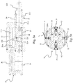
Fig. 3b is a sectional front view of a component of the rolling mill shown inFigures 2 and3a in said first operating condition (or contracted condition); -
Fig. 4 is a sectional side view of the components ofFig. 2 in a second operating condition (or expanded condition); -
Fig. 5a is a simplified view of some details of the side section ofFig. 4 ; -
Fig. 5b is a sectional front view of a component shown inFigures 4 and5a in said second operating condition (or expanded condition). - Referring now to the annexed drawings, in
Fig. 1 reference numeral 1 designates as a whole a rolling mill according to the present invention. - The
rolling mill 1 comprises a rolling stand (generically designated by reference numeral 2) comprising at least two rolls 3, between which a strip N to be rolled is made to pass; as is known, the typical purpose of rolling is to reduce the thickness of said strip N. - Preferably, said strip N is made of metal, e.g. steel, copper or alloys thereof, aluminium or alloys thereof; furthermore, said at least two rolls 3 are superimposed on each other and have substantially parallel axes.
- It must be pointed out that
Fig. 1 shows arolling mill 1 of the four-high type, in that therolling stand 2 comprises two work rolls and two support rolls (inFig. 1 , the work rolls and the support rolls are all designated by reference numeral 3); it is however clear that the provisions of the present invention may also be used in arolling mill 1 having a different configuration. - The rolling
mill 1 is equipped with at least onereel mandrel 10 for winding and/or unwinding said strip N during the rolling operations. - It should be noted that in
Fig. 1 said at least onereel reference numeral 4A inFig. 1 ), which allows unwinding the strip N to be rolled, and asecond winding reel 4B, which allows rewinding the strip N after it has passed through therolling stand 2. When the rollingmill 1 according to the present invention is of the reversible type, saidfirst reel 4A andsecond reel 4B can both, without distinction, be used for winding or unwinding the strip N. - It should also be noted that, in the present description, the term "strip N" refers to a product to be rolled of any typology.
- In addition, the
mandrel 10 comprises a clamping system (designated as a whole byreference numeral 20 inFigures 2 ,3a ,4 and5a ) associated with aslot 11 of themandrel 10 for clamping one end of the strip N in saidslot 11 during a step of winding the strip N on themandrel 10. - If the
rolling mill 1 is not of the reversible type, themandrel 10 of the present invention is associated with thesecond winding reel 4B; if therolling mill 1 is of the reversible type, themandrel 10 of the present invention can be associated, without distinction, with thefirst reel 4A and/ or with thesecond reel 4B. - Said
slot 11 extends along themandrel 10 substantially parallel to a longitudinal axis A (shown inFigures 2 and4 ) of themandrel 10. Moreover, as can be noticed inFig. 3 , saidslot 11 is oriented such that the intersection of a straight extension thereof P with a straight line T tangent to the circumference of themandrel 10 forms an angle a of 15° to 35°, in particular said angle a being approximately 25°. - In accordance with the present invention, the
clamping system 20 comprises at least one grip (or jaw) 20A forming a clamp together with aninner wall 11A of saidslot 11, said at least onegrip 20A being coupled to a closedhydraulic circuit clamping system 20, which allows said at least onegrip 20A to translate relative to thewall 11A, so as to switch from a first open position (shown inFigures 2 ,3a and 3b ), wherein the strip N can be inserted into saidslot 11, to a second closed position (shown inFigures 4 ,5a and 5b ), wherein the strip N can be clamped in saidslot 11, and vice versa (i.e. returning into the first open position shown inFigures 2 ,3a and 3b in order to release the strip N from saidslot 11 once the step of winding said strip N has been completed). - Preferably, the facing surfaces of the
wall 11A and of said at least onegrip 20A are substantially parallel to each other; in particular, said facing surfaces are substantially parallel to the straight line P (shown inFig. 3b ) that represents the extension of theslot 11. - In accordance with the present invention, said closed
hydraulic circuit cylinder 21 connected, via afirst duct 23 and asecond duct 24, to a second double-actingcylinder 22, saidsecond cylinder 22 being associated with said at least onegrip 20A. - In particular, said closed
hydraulic circuit - a first double-acting
cylinder 21 comprising a movable assembly consisting of afirst piston 21A connected to afirst rod 21B, wherein saidfirst piston 21A divides the inner body of thefirst cylinder 21 into afirst chamber 21C (which can also be defined as "piston-side chamber") and asecond chamber 21D (which can also be defined as rod-side chamber"); - a second double-acting
cylinder 22 comprising a movable assembly consisting of asecond piston 22A connected to asecond rod 22B, wherein saidsecond rod 22B is associated with said at least onegrip 20A, and wherein saidsecond piston 22A divides the inner body of thesecond cylinder 22 into afirst compartment 22C (which can also be defined as "piston-side compartment") and asecond compartment 22D (which can also be defined as "rod-side compartment"); - a
first duct 23 connecting saidfirst chamber 21C of thefirst cylinder 21 to saidfirst compartment 22C of thesecond cylinder 22; - a
second duct 24 connecting saidsecond chamber 21D of thefirst cylinder 21 to saidsecond compartment 22D of thesecond cylinder 22. - It is clear that the translational motion of said at least one
grip 20A relative to thewall 11A is effected through the motion of the first double-actingcylinder 21, which controls the motion of the second double-actingcylinder 22, thesecond rod 22B of which is associated with saidgrip 20A; as a result, said motion of the first double-actingcylinder 21 allows moving thesecond cylinder 22 and the assembly consisting of therod 22B and thegrip 20A in a manner such as to switch from said first open position (shown inFigures 2 ,3a and 3b ), wherein the strip N can be inserted into said slot 11), to said second closing position (shown inFigures 4 ,5a and 5b ), wherein the strip N can be clamped in saidslot 11, and vice versa. - In fact, when the
first piston 21A of thefirst cylinder 21 is in a condition in which it compresses thesecond chamber 21D ("rod-side chamber"), thesecond compartment 22D of thesecond cylinder 22 will be fed through thesecond duct 24, and thegrip 20A associated with thesecond rod 22B will be in the first open position (shown inFigures 3a and 3b ); as a consequence, when thegrip 20A is in said open position the strip N can be inserted into said slot 11 (in order to start winding the strip N on the mandrel 10) and/or said strip N can be removed from the slot 11 (when the winding of the strip N on themandrel 10 is complete). - On the contrary, when the
first piston 21A of thefirst cylinder 21 is in a condition in which it compresses thefirst chamber 21C ("piston-side chamber"), thefirst compartment 22C of thesecond cylinder 22 will be fed through thefirst duct 23, and thegrip 20A associated with thesecond rod 22B will be translated into said second closed position (shown inFigures 5a and 5b ) in order to clamp the strip N in saidslot 11 and allow winding the strip N on themandrel 10. - It is clear that, in order to cause the
grip 20A to return into the open position, it will be sufficient to actuate thefirst cylinder 21 so as to compress thesecond chamber 21D again and feed thesecond compartment 22D of thesecond cylinder 22 through thesecond duct 24. - It is therefore apparent that the provisions of the present invention allow realizing the
rolling mill 1 and themandrel 10 in such a way as to ensure an effective and reliable clamping of the strip N; in particular, theclamping system 20 according to the present invention comprises at least one grip (or jaw) 20A, which is made to translate by means of a closedhydraulic circuit - As shown in
Figures 3a and 3b , thefirst cylinder 21 is provided with a body that comprises two heads, wherein a first head is blind and a second head is crossed by thefirst rod 21B. -
Figures 2 and4 also show that said at least onegrip 20A comprises a plurality ofgrips 20A associated with a plurality ofsecond cylinders 22, in particular eachgrip 20A being associated with asecond rod 22B of asecond cylinder 22. Preferably, saidgrips 20A are arranged at regular intervals along saidslot 11 to ensure an optimal clamping of the strip N. - It should be noted that the
mandrel 10 according to the present invention may even have just onegrip 20A associated with a plurality ofsecond cylinders 22. - In a preferred embodiment, the
clamping system 20 according to the present invention comprises afirst compensation device 25 associated with said closedhydraulic circuit first compensation device 25 being associated with thefirst duct 23 in order to compensate for a variable closure of thesecond rod 22B and of thegrip 20A according to the thickness of the strip N and to compensate for the variable amount of fluid in thefirst chamber 21C of thefirst cylinder 21 and in thefirst compartment 22C of thesecond cylinder 22 caused by said variable closure. - Furthermore, the
clamping system 20 according to the present invention comprises asecond compensation device 26 associated with the closedhydraulic circuit second compensation device 26 being associated with thesecond duct 24 to ensure a constant and correct presence of fluid in thesecond chamber 21D of thefirst cylinder 21 and in thesecond compartment 22D of thesecond cylinder 22, in particular as a function of variable thicknesses of the strip N. Preferably, each one of thefirst compensation device 25 and thesecond compensation device 26 comprise a nitrogen cylinder; it is however clear that saidcompensation devices - It is therefore clear that the provisions of the
clamping system 20 andcompensation devices mill 1 and themandrel 10 in a manner such that they can effect an automatic clamping of the end of the strip N and can adapt themselves to strips N of different thickness, or to a strip N having thickness variations across its width. - Furthermore, the provisions of the present invention allow realizing the rolling
mill 1 and themandrel 10 in a manner such as to provide an adequate force for clamping the end of the strip N, i.e. a clamping force that ensures a reliable clamping of the strip N without damaging said end of the strip N, regardless of any thickness variations in said strip N. - In a preferred embodiment, the
mandrel 10 according to the present invention is of the expandable type and comprises at least one pair of sectors 12 (also known as "segments") associated with an actuation system (designated as a whole byreference numeral 30 inFigures 2 and4 ) that makes them radially movable, so that they can switch: - from an expanded condition, wherein the
sectors 12 are away from the center of themandrel 10 for executing a step of winding the strip N, in particular said expanded condition being such as to increase the diameter of themandrel 10, - to a contracted condition, wherein the
sectors 12 are brought closer to the center of themandrel 10 when the step of winding the strip N is complete, said contracted condition being such as to decrease the diameter of themandrel 10 to allow the strip N to be easily removed from themandrel 10 at the end of the step of winding the strip N. - In a preferred embodiment, the
mandrel 10 according to the present invention comprises foursectors 12 radially movable; it is however clear that the number ofsectors 12 may also be different. - It must be pointed out that, in said
expandable mandrel 10, theclamping system 20 and theslot 11 are associated with at least one of thesectors 12 of themandrel 10. - In accordance with the present invention, said clamping
system 20 is associated with theactuation system 30 in a manner such that it will be activated (i.e. in said closed position for clamping an end of the strip N in said slot 11) when thesectors 12 are in said expanded condition, and in a manner such that it will be deactivated (i.e. in said open position for releasing the end of the strip N from said slot 11) when thesectors 12 are in said contracted condition. - In a preferred embodiment, the
actuation system 30 comprises acontrol rod 31 provided with a plurality ofappendices 31A coupled to a plurality ofsliders 32 and to thefirst rod 21B of thefirst cylinder 21, in particular eachslider 32 being associated with arespective sector 12 for causing it to move into said expanded condition and into said contracted condition. - As a consequence, in said preferred embodiment the number N of
appendices 31A is equal to the number n ofsliders 32 plus one unit (i.e. N=n+1); in fact, theappendix 31A of thecontrol rod 31 in excess of the number n ofsliders 32 is the one that is to be coupled to thefirst rod 21B of thefirst cylinder 21. - In such an embodiment, each
slider 32 is provided with an inclined plane that couples to a respective inclined plane on the surface of thesector 12 facing the center of the mandrel 10 (note that said inclined planes are shown inFigures 2 and4 ), for causing said movement of eachsector 12 from the expanded condition to the contracted condition, and vice versa. - As a result, the displacement of the
control rod 31 and of theslider 32 in a first direction D1 and in a second direction D2 (shown inFigures 2 and4 ) allows thesectors 12 to switch from said contracted condition to said expanded condition, and vice versa; in particular, said first direction D1 and second direction D2 are substantially parallel to the longitudinal axis A of themandrel 10. - It is however clear that the
actuation system 30 may also be embodied differently than previously described and shown inFigures 2 and4 . - It is therefore apparent that the provisions of the
clamping system 20 according to the present invention and of the coupling thereof to theactuation system 30 allow avoiding a duplication of the elements required for activating the same, resulting in lower production costs and easier manufacturing of the rollingmill 1. Furthermore, the provisions of the present invention ensure that an adequate force will be available for clamping the end of the strip N, i.e. a clamping force that will ensure a reliable clamping of the strip N without damaging the end of the strip N being clamped, regardless of the diameter variation between the expanded and contracted conditions of themandrel 10. - The
actuation system 30 according to the present invention may then comprisereturn elements 33 for facilitating the switching of saidsectors 12 from the expanded condition to the contracted condition; in particular, saidreturn elements 33 may comprise elastic elements (e.g. springs) adapted to exert a thrust on saidsectors 12 towards the center of themandrel 10. - In light of the above description, it is possible to understand the method of operation of the rolling
mill 1 according to the present invention, said rollingmill 1 comprising: - a rolling
stand 2 comprising at least two rolls 3 between which a strip N to be rolled is made to pass; - at least one
reel mandrel 10 for winding and/ or unwinding said strip N during the rolling operations, wherein saidmandrel 10 comprises aclamping system 20 associated with aslot 11 of themandrel 10 for clamping one end of the strip N in saidslot 11 during a step of winding the strip N on themandrel 10. - In accordance with the present invention, said method of operation comprises the step a) of activating a closed
hydraulic circuit grip 20A of theclamping system 20 in order cause said at least onegrip 20A to translate relative to awall 11A of theslot 11, this movement allowing said at least onegrip 20A to switch from a first open position (shown inFigures 2 ,3a and 3b ), wherein the strip N can be inserted into saidslot 11, to a second closed position (shown inFigures 4 ,5a and 5b ), wherein the strip N can be clamped in saidslot 11, and vice versa. - In particular, the step a) of activating said closed
hydraulic circuit cylinder 21 connected, via afirst duct 23 and asecond duct 24, to a second double-actingcylinder 22, saidsecond cylinder 22 comprising asecond rod 22B associated with said at least onegrip 20A. - Furthermore, said step b) of moving the
first cylinder 21 is carried out by means of the following steps: - c) effecting a displacement of the
first cylinder 21 in a first direction D1 (seeFig. 2 ), in a manner such that afirst piston 21A of thefirst cylinder 21 will compress asecond chamber 21D in order to feed asecond compartment 22D of thesecond cylinder 22 through thesecond duct 24 and bring thegrip 20A associated with thesecond rod 22B into the first open position (shown inFigures 2 ,3a and 3b ), so that the strip N can be inserted into and/or removed from saidslot 11; - d) effecting a displacement of the
first cylinder 21 in a second direction D2 (seeFig. 4 ), in a manner such that thefirst piston 21A of thefirst cylinder 21 will compress afirst chamber 21C in order to feed afirst compartment 22C of thesecond cylinder 22 through thefirst duct 23 and bring thegrip 20A associated with thesecond rod 22B into the second closed position (shown inFigures 4 ,5a and 5b ), so that the strip N can be clamped in saidslot 11 and wound on themandrel 10. - It is then clear that, once the winding of the strip N on the
mandrel 10 is complete, it will be sufficient to move thefirst cylinder 21 in said first direction D1 in order to bring thegrip 20A into the first open position to allow the strip N to be removed from theslot 11. - The method according to the present invention may also comprise a step e) of effecting a compensation of the amount of fluid in the closed
hydraulic circuit first compensation device 25 associated with thefirst duct 23 and/ or asecond compensation device 26 associated with thesecond duct 24. In a preferred embodiment, steps a) to d) of the method of operation according to the present invention are carried out by means of a step f) of activating anactuation system 30 that makes at least one pair ofsectors 12 of themandrel 10 radially movable, saidactuation system 30 being associated with theclamping system 20 in a manner such that theclamping system 20 will be: - in said first open position, wherein the strip N can be inserted into said
slot 11 and/or removed from theslot 11, when thesectors 12 are in a contracted condition (i.e. closer to the center of themandrel 10, as particularly visible inFig. 3b ); - in said second closing position, wherein one end of the strip N can be clamped in said
slot 11, when thesectors 12 are in an expanded condition (i.e. farther from the center of themandrel 10, as particularly visible inFig. 5b ). - According to the method of operation, said step f) of activating an
actuation system 30 is carried out by a displacement of acontrol rod 31 of the actuation system 39 in said first direction D1 and second direction D2, in particular saidcontrol rod 31 being provided with anappendix 31A coupled to thefirst rod 21B of thefirst cylinder 21. - The advantages of a rolling
mill 1, a related mandrel and a related method of operation according to the present invention are apparent from the above description. - Such advantages lie in the fact the provisions of the present invention allow realizing the rolling
mill 1 and themandrel 10 in such a way as to attain an effective and reliable clamping of the strip N. - In fact, the
clamping system 20 according to the present invention comprises at least one grip (or jaw) 20A that is made to move through a translational motion by means of a closedhydraulic circuit - Another advantage of the present invention lies in the fact that the provisions of the
clamping system 20 andcompensation devices mill 1 and themandrel 10 in a manner such that they can ensure an automatic clamping of the end of the strip N and can adapt themselves to strips N of different thickness, or to a strip N having thickness variations across its width. - Furthermore, the provisions of the present invention allow realizing the rolling
mill 1 and themandrel 10 in a manner such that an adequate force will be available for clamping the end of the strip N, i.e. a clamping force that will ensure a reliable clamping of the strip N without damaging the end of the strip N being clamped, regardless of any thickness differences in said strip N. - In addition, the provision of the
clamping system 20 according to the present invention and its coupling to theactuation system 30 allows avoiding a duplication of the elements required for their activation, resulting in lower production costs and easier manufacturing of themandrel 10 and reel 4A, 4B. - Furthermore, the provisions of the present invention ensure that an adequate force will be available for clamping the end of the strip N, i.e. a clamping force that will ensure a reliable clamping of the strip N without damaging the end of the strip N being clamped, regardless of any diameter difference between the expanded and contracted conditions of the
mandrel 10. - The rolling mill, the mandrel and the method of operation described herein by way of example may be subject to many possible variations without departing from the novelty spirit of the inventive idea; it is also clear that in the practical implementation of the invention the illustrated details may have different shapes or be replaced with other technically equivalent elements.
- It can therefore be easily understood that the present invention is not limited to the above-described rolling mill, mandrel and method of operation, but may be subject to many modifications, improvements or replacements of equivalent parts and elements without departing from the inventive idea, as clearly specified in the following claims.
Claims (16)
- Rolling mill (1) comprising:- a rolling stand (2) comprising at least two rolls (3) between which a strip (N) to be rolled is made to pass;- at least one reel (4A, 4B) comprising a mandrel (10) for winding and/or unwinding said strip (N) during the rolling operations, wherein said mandrel (10) comprises a clamping system (20) associated with a slot (11) of the mandrel (10) for clamping one end of the strip (N) in said slot (11) during a step of winding the strip (N) on the mandrel (10),characterized in that
the clamping system (20) comprises at least one grip (20A) forming a clamp together with an inner wall (11A) of said slot (11), said at least one grip (20A) being coupled to a closed hydraulic circuit (21, 22, 23, 24) of the clamping system (20), which allows said at least one grip (20A) to translate relative to the wall (11A), so as to switch from a first open position, wherein the strip (N) can be inserted into said slot (11), to a second closed position, wherein the strip (N) can be clamped in said slot (11), and vice versa. - Rolling mill (1) according to claim 1, characterized in that said closed hydraulic circuit (21, 22, 23, 24) comprises a first double-acting cylinder (21) connected, via a first duct (23) and a second duct (24), to a second double-acting cylinder (22), said second cylinder (22) being associated with said at least one grip (20A).
- Rolling mill (1) according to one or more of the preceding claims, characterized in that said closed hydraulic circuit (21, 22, 23, 24) comprises:- a first double-acting cylinder (21) comprising a movable assembly consisting of a first piston (21A) connected to a first rod (21B), wherein said first piston (21A) divides the inner body of the first cylinder (21) into a first chamber (21C) and a second chamber (21D);- a second double-acting cylinder (22) comprising a movable assembly consisting of a second piston (22A) connected to a second rod (22B), wherein said second rod (22B) is associated with said at least one grip (20A), and wherein said second piston (22A) divides the inner body of the second cylinder (22) into a first compartment (22C) and a second compartment (22D);- a first duct (23) connecting said first chamber (21C) of the first cylinder (21) to said first compartment (22C) of the second cylinder (22);- a second duct (24) connecting said second chamber (21D) of the first cylinder (21) to said second compartment (22D) of the second cylinder (22).
- Rolling mill (1) according to one or more of the preceding claims, characterized in that the clamping system (20) comprises a first compensation device (25) associated with said closed hydraulic circuit (21, 22, 23, 24), in particular said first compensation device (25) being associated with the first duct (23) in order to compensate for a variable closure of the second rod (22B) and of the grip (20A) according to the thickness of the strip (N) and to compensate for the variable amount of fluid in the first chamber (21C) of the first cylinder (21) and in the first compartment (22C) of the second cylinder (22) caused by said variable closure.
- Rolling mill (1) according to claim 4, characterized in that the clamping system (20) comprises a second compensation device (26) associated with said closed hydraulic circuit (21, 22, 23, 24), in particular said second compensation device (26) being associated with the second duct (24) in order to ensure a constant and correct presence of fluid in the second chamber (21D) of the first cylinder (21) and in the second compartment (22D) of the second cylinder (22), in particular as a function of variable thicknesses of the strip (N).
- Rolling mill (1) according to one or more of the preceding claims, characterized in that the mandrel (10) is of the expandable type and comprises at least one pair of sectors (12) associated with an actuation system (30) that makes them radially movable, so that they can switch:- from an expanded condition, wherein the sectors (12) are away from the center of the mandrel (10) for executing a step of winding the strip (N), in particular said expanded condition being such as to increase the diameter of the mandrel (10),- to a contracted condition, wherein the sectors (12) are brought closer to the center of the mandrel (10) when the step of winding the strip (N) is complete, said contracted condition being such as to decrease the diameter of the mandrel (10) to allow the strip (N) to be easily removed from the mandrel (10) at the end of the step of winding the strip (N).
- Rolling mill (1) according to claim 6, characterized in that said clamping system (20) is associated with the actuation system (30) in a manner such that it will be in said closed position when the sectors (12) are in said expanded condition, and in a manner such that it will be in said open position when the sectors (12) are in said contracted condition.
- Rolling mill (1) according to one or more of the preceding claims 6 and 7, characterized in that the actuation system (30) comprises a control rod (31) provided with a plurality of appendices (31A) coupled to a plurality of sliders (32) and to the first rod (21B) of the first cylinder (21), in particular each slider (32) being associated with a respective sector (12) for causing it to move into said expanded condition and into said contracted condition.
- Rolling mill (1) according to claim 8, characterized in that each slider (32) is provided with an inclined plane that couples to a respective inclined plane on the surface of the sector (12) facing the center of the mandrel (10), for causing said movement of each sector (12) from the expanded condition to the contracted condition, and vice versa.
- Method of operation of a rolling mill (1) comprising:- a rolling stand (2) comprising at least two rolls (3) between which a strip (N) to be rolled is made to pass;- at least one reel (4A, 4B) comprising a mandrel (10) for winding and/or unwinding said strip (N) during the rolling operations, wherein said mandrel (10) comprises a clamping system (20) associated with a slot (11) of the mandrel (10) for clamping one end of the strip (N) in said slot (11) during a step of winding the strip (N) on the mandrel (10),said method being characterized in that it comprises the step a) of activating a closed hydraulic circuit (21, 22, 23, 24) coupled to at least one grip (20A) of the clamping system (20) in order to cause said at least one grip (20A) to translate relative to a wall (11A) of the slot (11), this movement allowing said at least one grip (20A) to switch from a first open position, wherein the strip (N) can be inserted into said slot (11), to a second closed position, wherein the strip (N) can be clamped in said slot (11), and vice versa.
- Method according to claim 10, characterized in that said step a) of activating said closed hydraulic circuit (21, 22, 23, 24) is carried out by means of a step b) of moving a first double-acting cylinder (21) connected, via a first duct (23) and a second duct (24), to a second double-acting cylinder (22), said second cylinder (22) comprising a second rod (22B) associated with said at least one grip (20A).
- Method according to claim 11, characterized in that said step b) of moving the first double-acting cylinder (21) is carried out by means of the following steps:c) effecting a displacement of the first cylinder (D1) in a first direction (21A), in a manner such that a first piston (21) of the first cylinder (21D) will compress a second chamber (22D) in order to feed a second compartment (22) of the second cylinder (22) through the second duct (24) and bring the grip (20A) associated with the second rod (22B) into the first open position, so that the strip (N) can be inserted into and/or removed from said slot (11);d) effecting a displacement of the first cylinder (21) in a second direction (D2), in a manner such that the first piston (21A) of the first cylinder (21) will compress a first chamber (21C) in order to feed a first compartment (22C) of the second cylinder (22) through the first duct (23) and bring the grip (20A) associated with the second rod (22B) into the second closed position, so that the strip (N) can be clamped in said slot (11) and wound on the mandrel (10).
- Method according to claim 12, characterized in that it comprises a step e) of effecting a compensation of the amount of fluid in the closed hydraulic circuit (21, 22, 23, 24) by means of a first compensation device (25) associated with the first duct (23) and/or a second compensation device (26) associated with the second duct (24).
- Method according to claim 12, characterized in that said steps a) to d) are carried out by means of a step f) of activating an actuation system (30) that makes at least one pair of sectors (12) of the mandrel (10) radially movable, said actuation system (30) being associated with the clamping system (20) in a manner such that the clamping system (20) will be:- in said first open position, wherein the strip (N) can be inserted into said slot (11) and/or removed from the slot (11), when the sectors (12) are in a contracted condition;- in said second closed position, wherein one end of the strip (N) can be clamped in said slot (11), when the sectors are in an expanded condition.
- Method according to claim 14, characterized in that said step f) is carried out by a displacement of a control rod (31) of the actuation system (30) in said first direction (D1) and second direction (D2), in particular said control rod (31) being provided with an appendix (31A) coupled to the first rod (21B) of the first cylinder (21).
- Mandrel (10) of a rolling mill (1) according to one or more of the preceding claims 1 to 9, and suitable for use in the method of operation according to one or more of the preceding claims 10 to 15.
Applications Claiming Priority (1)
| Application Number | Priority Date | Filing Date | Title |
|---|---|---|---|
| ITUA2016A002360A ITUA20162360A1 (en) | 2016-04-06 | 2016-04-06 | MILL INCLUDING A MANDREL OF IMPROVED TYPE, AND RELATED MANDREL AND OPERATING METHOD |
Publications (2)
| Publication Number | Publication Date |
|---|---|
| EP3241626A1 true EP3241626A1 (en) | 2017-11-08 |
| EP3241626B1 EP3241626B1 (en) | 2020-12-23 |
Family
ID=56551482
Family Applications (1)
| Application Number | Title | Priority Date | Filing Date |
|---|---|---|---|
| EP17164513.8A Active EP3241626B1 (en) | 2016-04-06 | 2017-04-03 | Rolling mill comprising a mandrel of improved type and related method of operation |
Country Status (2)
| Country | Link |
|---|---|
| EP (1) | EP3241626B1 (en) |
| IT (1) | ITUA20162360A1 (en) |
Families Citing this family (1)
| Publication number | Priority date | Publication date | Assignee | Title |
|---|---|---|---|---|
| CN115673027A (en) * | 2022-10-25 | 2023-02-03 | 金龙精密铜管集团股份有限公司 | A precision copper tube large loose disc take-up device |
Citations (5)
| Publication number | Priority date | Publication date | Assignee | Title |
|---|---|---|---|---|
| GB1098216A (en) * | 1965-06-25 | 1968-01-10 | Schloemann Ag | Improvements in winding drums for strip-like rolled stock |
| GB1159140A (en) * | 1967-10-27 | 1969-07-23 | Schloemann Ag | An Improved Winding Drum for Winding Rolled Strip |
| GB1207707A (en) * | 1967-02-14 | 1970-10-07 | Voest Ag | Improvements in or relating to coilers for upcoiling or uncoiling strip metal |
| US4352470A (en) * | 1981-03-27 | 1982-10-05 | Textron, Inc. | Combined payoff and winder for strip rolling mills |
| JPH04288929A (en) * | 1991-03-19 | 1992-10-14 | Yonemori Tekkosho:Kk | Clamping mechanism for recoiler |
-
2016
- 2016-04-06 IT ITUA2016A002360A patent/ITUA20162360A1/en unknown
-
2017
- 2017-04-03 EP EP17164513.8A patent/EP3241626B1/en active Active
Patent Citations (5)
| Publication number | Priority date | Publication date | Assignee | Title |
|---|---|---|---|---|
| GB1098216A (en) * | 1965-06-25 | 1968-01-10 | Schloemann Ag | Improvements in winding drums for strip-like rolled stock |
| GB1207707A (en) * | 1967-02-14 | 1970-10-07 | Voest Ag | Improvements in or relating to coilers for upcoiling or uncoiling strip metal |
| GB1159140A (en) * | 1967-10-27 | 1969-07-23 | Schloemann Ag | An Improved Winding Drum for Winding Rolled Strip |
| US4352470A (en) * | 1981-03-27 | 1982-10-05 | Textron, Inc. | Combined payoff and winder for strip rolling mills |
| JPH04288929A (en) * | 1991-03-19 | 1992-10-14 | Yonemori Tekkosho:Kk | Clamping mechanism for recoiler |
Also Published As
| Publication number | Publication date |
|---|---|
| ITUA20162360A1 (en) | 2017-10-06 |
| EP3241626B1 (en) | 2020-12-23 |
Similar Documents
| Publication | Publication Date | Title |
|---|---|---|
| EP0222231B1 (en) | Device for controlling the lifting and pressing movements of the pressure rollers of hot strip coilers | |
| EP3241626B1 (en) | Rolling mill comprising a mandrel of improved type and related method of operation | |
| CN107520278B (en) | The control method of inner ring of steel coil core pulling when preventing coiling machine from unloading volume | |
| CN106986206A (en) | It is particularly used for the telescopic pneumatic linear executing agency of the uncoiler with moveable arm | |
| DE102008030145A1 (en) | Method and device for winding metal strip | |
| EP3127626A1 (en) | Bending device for metallic plate | |
| EP3057782B1 (en) | System and method for gripping and handling a tire bead apex | |
| US10011457B2 (en) | Device for retaining a sleeve around a mandrel | |
| KR20120062817A (en) | Guide device for a strip rolling mill | |
| CN103754675B (en) | Internal lining paper reel clamping bracket and clamping method | |
| KR101174692B1 (en) | Expansion reel mandrel | |
| US5531398A (en) | Method and apparatus of removing a coil of material from a mandrel | |
| US3446450A (en) | Tension reel gripper mechanism | |
| US3774862A (en) | Reel for colling strip | |
| CN111570527B (en) | The control method of the guide plate during the switching process of the fully continuous hot-rolled thin strip coiler | |
| JP5442748B2 (en) | Edge bending press machine | |
| CN106553237B (en) | Film punching machine and punching method | |
| US3399450A (en) | Method and apparatus for joining strip ends | |
| JP6436574B2 (en) | Gripping device and gripping method | |
| US2703925A (en) | Tube end sizing apparatus and method | |
| EP2389259A1 (en) | Adjustment device for guide rollers and relative adjustment method | |
| KR102718026B1 (en) | Method and device for detecting the position of a side strip contour or strip edge of a running metal strip | |
| US2723805A (en) | Clamping device | |
| US2303143A (en) | Means for tensioning metallic material in cold reducing mills | |
| RU2004113768A (en) | METHOD FOR CONTACT BUTT WELDING OF STRIPS AND DEVICE FOR ITS IMPLEMENTATION |
Legal Events
| Date | Code | Title | Description |
|---|---|---|---|
| PUAI | Public reference made under article 153(3) epc to a published international application that has entered the european phase |
Free format text: ORIGINAL CODE: 0009012 |
|
| STAA | Information on the status of an ep patent application or granted ep patent |
Free format text: STATUS: THE APPLICATION HAS BEEN PUBLISHED |
|
| AK | Designated contracting states |
Kind code of ref document: A1 Designated state(s): AL AT BE BG CH CY CZ DE DK EE ES FI FR GB GR HR HU IE IS IT LI LT LU LV MC MK MT NL NO PL PT RO RS SE SI SK SM TR |
|
| AX | Request for extension of the european patent |
Extension state: BA ME |
|
| STAA | Information on the status of an ep patent application or granted ep patent |
Free format text: STATUS: REQUEST FOR EXAMINATION WAS MADE |
|
| 17P | Request for examination filed |
Effective date: 20180508 |
|
| RBV | Designated contracting states (corrected) |
Designated state(s): AL AT BE BG CH CY CZ DE DK EE ES FI FR GB GR HR HU IE IS IT LI LT LU LV MC MK MT NL NO PL PT RO RS SE SI SK SM TR |
|
| GRAP | Despatch of communication of intention to grant a patent |
Free format text: ORIGINAL CODE: EPIDOSNIGR1 |
|
| STAA | Information on the status of an ep patent application or granted ep patent |
Free format text: STATUS: GRANT OF PATENT IS INTENDED |
|
| RIC1 | Information provided on ipc code assigned before grant |
Ipc: B21C 47/18 20060101ALN20200608BHEP Ipc: B21C 47/28 20060101ALN20200608BHEP Ipc: B21C 47/32 20060101ALI20200608BHEP Ipc: B21C 47/04 20060101ALN20200608BHEP Ipc: B21C 47/30 20060101AFI20200608BHEP |
|
| INTG | Intention to grant announced |
Effective date: 20200715 |
|
| GRAS | Grant fee paid |
Free format text: ORIGINAL CODE: EPIDOSNIGR3 |
|
| GRAA | (expected) grant |
Free format text: ORIGINAL CODE: 0009210 |
|
| STAA | Information on the status of an ep patent application or granted ep patent |
Free format text: STATUS: THE PATENT HAS BEEN GRANTED |
|
| AK | Designated contracting states |
Kind code of ref document: B1 Designated state(s): AL AT BE BG CH CY CZ DE DK EE ES FI FR GB GR HR HU IE IS IT LI LT LU LV MC MK MT NL NO PL PT RO RS SE SI SK SM TR |
|
| REG | Reference to a national code |
Ref country code: GB Ref legal event code: FG4D |
|
| REG | Reference to a national code |
Ref country code: DE Ref legal event code: R096 Ref document number: 602017029869 Country of ref document: DE |
|
| REG | Reference to a national code |
Ref country code: AT Ref legal event code: REF Ref document number: 1347236 Country of ref document: AT Kind code of ref document: T Effective date: 20210115 |
|
| REG | Reference to a national code |
Ref country code: IE Ref legal event code: FG4D |
|
| PG25 | Lapsed in a contracting state [announced via postgrant information from national office to epo] |
Ref country code: RS Free format text: LAPSE BECAUSE OF FAILURE TO SUBMIT A TRANSLATION OF THE DESCRIPTION OR TO PAY THE FEE WITHIN THE PRESCRIBED TIME-LIMIT Effective date: 20201223 Ref country code: NO Free format text: LAPSE BECAUSE OF FAILURE TO SUBMIT A TRANSLATION OF THE DESCRIPTION OR TO PAY THE FEE WITHIN THE PRESCRIBED TIME-LIMIT Effective date: 20210323 Ref country code: FI Free format text: LAPSE BECAUSE OF FAILURE TO SUBMIT A TRANSLATION OF THE DESCRIPTION OR TO PAY THE FEE WITHIN THE PRESCRIBED TIME-LIMIT Effective date: 20201223 Ref country code: GR Free format text: LAPSE BECAUSE OF FAILURE TO SUBMIT A TRANSLATION OF THE DESCRIPTION OR TO PAY THE FEE WITHIN THE PRESCRIBED TIME-LIMIT Effective date: 20210324 |
|
| REG | Reference to a national code |
Ref country code: AT Ref legal event code: MK05 Ref document number: 1347236 Country of ref document: AT Kind code of ref document: T Effective date: 20201223 |
|
| REG | Reference to a national code |
Ref country code: NL Ref legal event code: MP Effective date: 20201223 |
|
| PG25 | Lapsed in a contracting state [announced via postgrant information from national office to epo] |
Ref country code: SE Free format text: LAPSE BECAUSE OF FAILURE TO SUBMIT A TRANSLATION OF THE DESCRIPTION OR TO PAY THE FEE WITHIN THE PRESCRIBED TIME-LIMIT Effective date: 20201223 Ref country code: BG Free format text: LAPSE BECAUSE OF FAILURE TO SUBMIT A TRANSLATION OF THE DESCRIPTION OR TO PAY THE FEE WITHIN THE PRESCRIBED TIME-LIMIT Effective date: 20210323 Ref country code: LV Free format text: LAPSE BECAUSE OF FAILURE TO SUBMIT A TRANSLATION OF THE DESCRIPTION OR TO PAY THE FEE WITHIN THE PRESCRIBED TIME-LIMIT Effective date: 20201223 |
|
| PG25 | Lapsed in a contracting state [announced via postgrant information from national office to epo] |
Ref country code: NL Free format text: LAPSE BECAUSE OF FAILURE TO SUBMIT A TRANSLATION OF THE DESCRIPTION OR TO PAY THE FEE WITHIN THE PRESCRIBED TIME-LIMIT Effective date: 20201223 Ref country code: HR Free format text: LAPSE BECAUSE OF FAILURE TO SUBMIT A TRANSLATION OF THE DESCRIPTION OR TO PAY THE FEE WITHIN THE PRESCRIBED TIME-LIMIT Effective date: 20201223 |
|
| REG | Reference to a national code |
Ref country code: LT Ref legal event code: MG9D |
|
| PG25 | Lapsed in a contracting state [announced via postgrant information from national office to epo] |
Ref country code: PT Free format text: LAPSE BECAUSE OF FAILURE TO SUBMIT A TRANSLATION OF THE DESCRIPTION OR TO PAY THE FEE WITHIN THE PRESCRIBED TIME-LIMIT Effective date: 20210423 Ref country code: SK Free format text: LAPSE BECAUSE OF FAILURE TO SUBMIT A TRANSLATION OF THE DESCRIPTION OR TO PAY THE FEE WITHIN THE PRESCRIBED TIME-LIMIT Effective date: 20201223 Ref country code: RO Free format text: LAPSE BECAUSE OF FAILURE TO SUBMIT A TRANSLATION OF THE DESCRIPTION OR TO PAY THE FEE WITHIN THE PRESCRIBED TIME-LIMIT Effective date: 20201223 Ref country code: CZ Free format text: LAPSE BECAUSE OF FAILURE TO SUBMIT A TRANSLATION OF THE DESCRIPTION OR TO PAY THE FEE WITHIN THE PRESCRIBED TIME-LIMIT Effective date: 20201223 Ref country code: EE Free format text: LAPSE BECAUSE OF FAILURE TO SUBMIT A TRANSLATION OF THE DESCRIPTION OR TO PAY THE FEE WITHIN THE PRESCRIBED TIME-LIMIT Effective date: 20201223 Ref country code: SM Free format text: LAPSE BECAUSE OF FAILURE TO SUBMIT A TRANSLATION OF THE DESCRIPTION OR TO PAY THE FEE WITHIN THE PRESCRIBED TIME-LIMIT Effective date: 20201223 Ref country code: LT Free format text: LAPSE BECAUSE OF FAILURE TO SUBMIT A TRANSLATION OF THE DESCRIPTION OR TO PAY THE FEE WITHIN THE PRESCRIBED TIME-LIMIT Effective date: 20201223 |
|
| PG25 | Lapsed in a contracting state [announced via postgrant information from national office to epo] |
Ref country code: AT Free format text: LAPSE BECAUSE OF FAILURE TO SUBMIT A TRANSLATION OF THE DESCRIPTION OR TO PAY THE FEE WITHIN THE PRESCRIBED TIME-LIMIT Effective date: 20201223 Ref country code: PL Free format text: LAPSE BECAUSE OF FAILURE TO SUBMIT A TRANSLATION OF THE DESCRIPTION OR TO PAY THE FEE WITHIN THE PRESCRIBED TIME-LIMIT Effective date: 20201223 |
|
| REG | Reference to a national code |
Ref country code: DE Ref legal event code: R097 Ref document number: 602017029869 Country of ref document: DE |
|
| PG25 | Lapsed in a contracting state [announced via postgrant information from national office to epo] |
Ref country code: IS Free format text: LAPSE BECAUSE OF FAILURE TO SUBMIT A TRANSLATION OF THE DESCRIPTION OR TO PAY THE FEE WITHIN THE PRESCRIBED TIME-LIMIT Effective date: 20210423 |
|
| PG25 | Lapsed in a contracting state [announced via postgrant information from national office to epo] |
Ref country code: AL Free format text: LAPSE BECAUSE OF FAILURE TO SUBMIT A TRANSLATION OF THE DESCRIPTION OR TO PAY THE FEE WITHIN THE PRESCRIBED TIME-LIMIT Effective date: 20201223 |
|
| PLBE | No opposition filed within time limit |
Free format text: ORIGINAL CODE: 0009261 |
|
| STAA | Information on the status of an ep patent application or granted ep patent |
Free format text: STATUS: NO OPPOSITION FILED WITHIN TIME LIMIT |
|
| PG25 | Lapsed in a contracting state [announced via postgrant information from national office to epo] |
Ref country code: DK Free format text: LAPSE BECAUSE OF FAILURE TO SUBMIT A TRANSLATION OF THE DESCRIPTION OR TO PAY THE FEE WITHIN THE PRESCRIBED TIME-LIMIT Effective date: 20201223 Ref country code: MC Free format text: LAPSE BECAUSE OF FAILURE TO SUBMIT A TRANSLATION OF THE DESCRIPTION OR TO PAY THE FEE WITHIN THE PRESCRIBED TIME-LIMIT Effective date: 20201223 |
|
| 26N | No opposition filed |
Effective date: 20210924 |
|
| GBPC | Gb: european patent ceased through non-payment of renewal fee |
Effective date: 20210403 |
|
| PG25 | Lapsed in a contracting state [announced via postgrant information from national office to epo] |
Ref country code: LU Free format text: LAPSE BECAUSE OF NON-PAYMENT OF DUE FEES Effective date: 20210403 |
|
| REG | Reference to a national code |
Ref country code: BE Ref legal event code: MM Effective date: 20210430 |
|
| PG25 | Lapsed in a contracting state [announced via postgrant information from national office to epo] |
Ref country code: CH Free format text: LAPSE BECAUSE OF NON-PAYMENT OF DUE FEES Effective date: 20210430 Ref country code: LI Free format text: LAPSE BECAUSE OF NON-PAYMENT OF DUE FEES Effective date: 20210430 Ref country code: ES Free format text: LAPSE BECAUSE OF FAILURE TO SUBMIT A TRANSLATION OF THE DESCRIPTION OR TO PAY THE FEE WITHIN THE PRESCRIBED TIME-LIMIT Effective date: 20201223 Ref country code: GB Free format text: LAPSE BECAUSE OF NON-PAYMENT OF DUE FEES Effective date: 20210403 Ref country code: FR Free format text: LAPSE BECAUSE OF NON-PAYMENT OF DUE FEES Effective date: 20210430 |
|
| PG25 | Lapsed in a contracting state [announced via postgrant information from national office to epo] |
Ref country code: SI Free format text: LAPSE BECAUSE OF FAILURE TO SUBMIT A TRANSLATION OF THE DESCRIPTION OR TO PAY THE FEE WITHIN THE PRESCRIBED TIME-LIMIT Effective date: 20201223 |
|
| PG25 | Lapsed in a contracting state [announced via postgrant information from national office to epo] |
Ref country code: IE Free format text: LAPSE BECAUSE OF NON-PAYMENT OF DUE FEES Effective date: 20210403 |
|
| PG25 | Lapsed in a contracting state [announced via postgrant information from national office to epo] |
Ref country code: IS Free format text: LAPSE BECAUSE OF FAILURE TO SUBMIT A TRANSLATION OF THE DESCRIPTION OR TO PAY THE FEE WITHIN THE PRESCRIBED TIME-LIMIT Effective date: 20210423 |
|
| PG25 | Lapsed in a contracting state [announced via postgrant information from national office to epo] |
Ref country code: BE Free format text: LAPSE BECAUSE OF NON-PAYMENT OF DUE FEES Effective date: 20210430 |
|
| PG25 | Lapsed in a contracting state [announced via postgrant information from national office to epo] |
Ref country code: HU Free format text: LAPSE BECAUSE OF FAILURE TO SUBMIT A TRANSLATION OF THE DESCRIPTION OR TO PAY THE FEE WITHIN THE PRESCRIBED TIME-LIMIT; INVALID AB INITIO Effective date: 20170403 |
|
| P01 | Opt-out of the competence of the unified patent court (upc) registered |
Effective date: 20230426 |
|
| PG25 | Lapsed in a contracting state [announced via postgrant information from national office to epo] |
Ref country code: CY Free format text: LAPSE BECAUSE OF FAILURE TO SUBMIT A TRANSLATION OF THE DESCRIPTION OR TO PAY THE FEE WITHIN THE PRESCRIBED TIME-LIMIT Effective date: 20201223 |
|
| PG25 | Lapsed in a contracting state [announced via postgrant information from national office to epo] |
Ref country code: MK Free format text: LAPSE BECAUSE OF FAILURE TO SUBMIT A TRANSLATION OF THE DESCRIPTION OR TO PAY THE FEE WITHIN THE PRESCRIBED TIME-LIMIT Effective date: 20201223 |
|
| PG25 | Lapsed in a contracting state [announced via postgrant information from national office to epo] |
Ref country code: MT Free format text: LAPSE BECAUSE OF FAILURE TO SUBMIT A TRANSLATION OF THE DESCRIPTION OR TO PAY THE FEE WITHIN THE PRESCRIBED TIME-LIMIT Effective date: 20201223 |
|
| PGFP | Annual fee paid to national office [announced via postgrant information from national office to epo] |
Ref country code: DE Payment date: 20250430 Year of fee payment: 9 |
|
| PGFP | Annual fee paid to national office [announced via postgrant information from national office to epo] |
Ref country code: IT Payment date: 20250428 Year of fee payment: 9 |
|
| PG25 | Lapsed in a contracting state [announced via postgrant information from national office to epo] |
Ref country code: TR Free format text: LAPSE BECAUSE OF FAILURE TO SUBMIT A TRANSLATION OF THE DESCRIPTION OR TO PAY THE FEE WITHIN THE PRESCRIBED TIME-LIMIT Effective date: 20201223 |