EP3241582A1 - Device for protecting an injection apparatus, in particular an injection apparatus for medical use, such as a syringe - Google Patents
Device for protecting an injection apparatus, in particular an injection apparatus for medical use, such as a syringe Download PDFInfo
- Publication number
- EP3241582A1 EP3241582A1 EP17171382.9A EP17171382A EP3241582A1 EP 3241582 A1 EP3241582 A1 EP 3241582A1 EP 17171382 A EP17171382 A EP 17171382A EP 3241582 A1 EP3241582 A1 EP 3241582A1
- Authority
- EP
- European Patent Office
- Prior art keywords
- sleeve
- leg
- bearing surface
- injection apparatus
- protective position
- Prior art date
- Legal status (The legal status is an assumption and is not a legal conclusion. Google has not performed a legal analysis and makes no representation as to the accuracy of the status listed.)
- Granted
Links
Images

Classifications
-
- A—HUMAN NECESSITIES
- A61—MEDICAL OR VETERINARY SCIENCE; HYGIENE
- A61M—DEVICES FOR INTRODUCING MEDIA INTO, OR ONTO, THE BODY; DEVICES FOR TRANSDUCING BODY MEDIA OR FOR TAKING MEDIA FROM THE BODY; DEVICES FOR PRODUCING OR ENDING SLEEP OR STUPOR
- A61M5/00—Devices for bringing media into the body in a subcutaneous, intra-vascular or intramuscular way; Accessories therefor, e.g. filling or cleaning devices, arm rests
- A61M5/178—Syringes
- A61M5/31—Details
- A61M5/32—Needles; Details of needles pertaining to their connection with syringe or hub; Accessories for bringing the needle into, or holding the needle on, the body; Devices for protection of needles
- A61M5/3205—Apparatus for removing or disposing of used needles or syringes, e.g. containers; Means for protection against accidental injuries from used needles
- A61M5/321—Means for protection against accidental injuries by used needles
- A61M5/3243—Means for protection against accidental injuries by used needles being axially-extensible, e.g. protective sleeves coaxially slidable on the syringe barrel
- A61M5/326—Fully automatic sleeve extension, i.e. in which triggering of the sleeve does not require a deliberate action by the user
-
- A—HUMAN NECESSITIES
- A61—MEDICAL OR VETERINARY SCIENCE; HYGIENE
- A61M—DEVICES FOR INTRODUCING MEDIA INTO, OR ONTO, THE BODY; DEVICES FOR TRANSDUCING BODY MEDIA OR FOR TAKING MEDIA FROM THE BODY; DEVICES FOR PRODUCING OR ENDING SLEEP OR STUPOR
- A61M5/00—Devices for bringing media into the body in a subcutaneous, intra-vascular or intramuscular way; Accessories therefor, e.g. filling or cleaning devices, arm rests
- A61M5/178—Syringes
- A61M5/31—Details
- A61M5/32—Needles; Details of needles pertaining to their connection with syringe or hub; Accessories for bringing the needle into, or holding the needle on, the body; Devices for protection of needles
- A61M5/3205—Apparatus for removing or disposing of used needles or syringes, e.g. containers; Means for protection against accidental injuries from used needles
- A61M5/321—Means for protection against accidental injuries by used needles
- A61M5/3243—Means for protection against accidental injuries by used needles being axially-extensible, e.g. protective sleeves coaxially slidable on the syringe barrel
- A61M5/3245—Constructional features thereof, e.g. to improve manipulation or functioning
- A61M2005/3247—Means to impede repositioning of protection sleeve from needle covering to needle uncovering position
-
- A—HUMAN NECESSITIES
- A61—MEDICAL OR VETERINARY SCIENCE; HYGIENE
- A61M—DEVICES FOR INTRODUCING MEDIA INTO, OR ONTO, THE BODY; DEVICES FOR TRANSDUCING BODY MEDIA OR FOR TAKING MEDIA FROM THE BODY; DEVICES FOR PRODUCING OR ENDING SLEEP OR STUPOR
- A61M5/00—Devices for bringing media into the body in a subcutaneous, intra-vascular or intramuscular way; Accessories therefor, e.g. filling or cleaning devices, arm rests
- A61M5/178—Syringes
- A61M5/31—Details
- A61M5/32—Needles; Details of needles pertaining to their connection with syringe or hub; Accessories for bringing the needle into, or holding the needle on, the body; Devices for protection of needles
- A61M5/3205—Apparatus for removing or disposing of used needles or syringes, e.g. containers; Means for protection against accidental injuries from used needles
- A61M5/321—Means for protection against accidental injuries by used needles
- A61M5/3243—Means for protection against accidental injuries by used needles being axially-extensible, e.g. protective sleeves coaxially slidable on the syringe barrel
- A61M5/326—Fully automatic sleeve extension, i.e. in which triggering of the sleeve does not require a deliberate action by the user
- A61M2005/3261—Fully automatic sleeve extension, i.e. in which triggering of the sleeve does not require a deliberate action by the user triggered by radial deflection of the anchoring parts between sleeve and syringe barrel, e.g. spreading of sleeve retaining hooks having slanted surfaces by engagement with conically shaped collet of the piston rod during the last portion of the injection stroke of the plunger
-
- A—HUMAN NECESSITIES
- A61—MEDICAL OR VETERINARY SCIENCE; HYGIENE
- A61M—DEVICES FOR INTRODUCING MEDIA INTO, OR ONTO, THE BODY; DEVICES FOR TRANSDUCING BODY MEDIA OR FOR TAKING MEDIA FROM THE BODY; DEVICES FOR PRODUCING OR ENDING SLEEP OR STUPOR
- A61M5/00—Devices for bringing media into the body in a subcutaneous, intra-vascular or intramuscular way; Accessories therefor, e.g. filling or cleaning devices, arm rests
- A61M5/178—Syringes
- A61M5/31—Details
- A61M5/32—Needles; Details of needles pertaining to their connection with syringe or hub; Accessories for bringing the needle into, or holding the needle on, the body; Devices for protection of needles
- A61M5/3205—Apparatus for removing or disposing of used needles or syringes, e.g. containers; Means for protection against accidental injuries from used needles
- A61M5/321—Means for protection against accidental injuries by used needles
- A61M5/3243—Means for protection against accidental injuries by used needles being axially-extensible, e.g. protective sleeves coaxially slidable on the syringe barrel
- A61M5/3271—Means for protection against accidental injuries by used needles being axially-extensible, e.g. protective sleeves coaxially slidable on the syringe barrel with guiding tracks for controlled sliding of needle protective sleeve from needle exposing to needle covering position
Definitions
- the present invention concerns a device for protecting an injection apparatus, in particular an injection apparatus for medical use such as a syringe.
- distal end of a part or of the device is considered to be the end farthest away from the injection site.
- distal direction refers to the direction of injection
- proximal direction designates the direction opposite the direction of injection.
- a device for protecting an injection apparatus comprising a body in which the injection apparatus is placed, a sleeve mobile in relation to this body, means enabling the mobility of this sleeve and means enabling the sleeve to be locked in the protective position.
- the sleeve can be moved between a non-protective position, in which an injection member comprised by the injection apparatus is exposed so as to allow injection, and a protective position, in which the sleeve completely covers the injection member so as to eliminate the risk of contamination of the user by this injection member and to prevent reuse of the injection apparatus.
- Said injection member is the needle of a syringe when the injection apparatus is a syringe.
- Document WO 2005/030301 in the applicant's name, illustrates one such protection device.
- the means allowing locking of the sleeve 3A in the protective position comprise at least one flexible proximal leg 7A integral with the sleeve 3A, being engaged, in the protective position, behind a corresponding distal edge 51A arranged at the end of a rib 5A integral with said body.
- the sleeve 3A also comprises, at its proximal part, at least one wall 10A adjacent to the leg 7A, which protrudes in the proximal direction.
- the flexible leg 7A has a relatively significant length (it is also part of the means allowing the mobility of the sleeve 3A, being, in the non-protective position, hooked on a proximal rim formed by the rib 5A and, at the end of injection, being bent by a cam surface actuated by the piston rod so as to be freed from this rim).
- It also has a relatively reduced thickness, such that it can assume a position between the body of the syringe and the body of the device, and is in a material having a degree of elastic flexibility, so that it can be deformed between its hooked position making it possible to maintain the sleeve 3A in the non-protective position and its unhooked position allowing movement of this sleeve 3A toward the protective position.
- the present invention aims to improve the structure of the protection device as previously stated, known by the earlier document mentioned above.
- the device to which the invention relates comprises, in a known manner, a body in which the injection apparatus is placed, a sleeve mobile in relation to said body, means for moving said sleeve in relation to the body, and locking means allowing locking of the sleeve in a protective position; the sleeve can be moved between a non-protective position, in which an injection member comprised by the injection apparatus is exposed so as to allow injection, and said protective position, in which the sleeve completely covers the injection member; said locking means comprise at least one flexible proximal leg integral with the sleeve, forming a first bearing surface by which this leg engages, in said protective position, behind at least a first corresponding distal bearing surface of said body; the flexible leg has a reduced thickness, such that it can assume a position between a wall of the injection apparatus and said body of the device.
- the additional bearing surface thus arranged make it possible to increase the bearing surface of the leg with the rest of the device and therefore to better distribute the surface on which the force undergone by the leg is exerted during an action tending to return the sleeve to the non-protective position.
- the result is that the leg according to the invention has greatly increased resistance relative to that of the device according to the prior art, which makes it possible to effectively prevent all attempts to force the sleeve toward its non-protective position.
- the resistance measured to such a forcing has shown itself to be greatly sufficient to obtain the desired protection in all cases.
- said additional bearing surfaces of the leg and of the device are arranged in a location located substantially between one-third and two-thirds of the length of the leg (i.e. the dimension of the latter extending along the axis of sliding of the sleeve).
- the leg when it is intended to be elastically deformed to engage behind said first distal bearing surface, comprises an area having a reduced cross-section, located away from said additional bearing surfaces.
- This area having a reduced cross-section makes it possible to increase the flexibility of the leg so as to promote its engagement behind said first distal bearing surface; this flexibility also makes it possible to promote the coming of said additional bearing surfaces into mutual cooperation when the leg is subject to the force generated by the action returning the sleeve to the non-protective position.
- said area having a reduced cross-section may be subject to compression in the longitudinal direction of the leg ensuring elimination of these clearances and therefore the perfect coming into mutual contact of the additional bearing surfaces.
- Figures 2 and 3 illustrate a device 1 for protecting an injection apparatus, in particular an injection apparatus for medical use, which, in the illustrated example, is a syringe.
- the device 1 comprises a body 2 in which are placed the syringe body 100, a sleeve 3 mobile in relation to this body 2, a spring 4 for moving this sleeve 3 in relation to the body 2, and a locking assembly 5, 6, 7 enabling locking of the sleeve 3 in the illustrated position, called the "protective position".
- the device is very similar to that described in document N° WO 2005/030301 , in the applicant's name, to which one may refer for more detailed explanations.
- the body 2 is tubular and has a length such that it can house the syringe body 100, but that the needle of this syringe protrudes beyond the distal end of said body 2 when the sleeve 3 is in a "non-protective" position. In this position, the sleeve 3 is completely drawn into the body 2, assuming a position between the wall of the latter and the syringe body 100, and the spring 4, inserted between the sleeve 3 and a proximal ring which receives the body 2, is stressed.
- the body 2 comprises two diametrically opposed ribs 5, integral with said body and protruding inwardly, one of which is illustrated in figures 2 and 3 notwithstanding the longitudinal cross-section of the body 2.
- Each rib 5 comprises notched ends designed to cooperate with a pair of proximal legs 6, 7 comprised by the sleeve 3, in the same way as described in the aforementioned document N° WO 2005/030301 .
- these proximal legs 6 and 7 hook on the proximal end of the rib 5, and thereby ensure maintenance of the sleeve 3 in this position notwithstanding the elastic return force of the spring 4; at the end of injection, these legs 6, 7 are elastically deformed by cam-shaped projections 8 arranged on a proximal ring 9, itself moved by the piston rod of the syringe, such that they are unhooked from the rib 5; the sleeve 3 thus being freed, the spring 4 relaxes and brings this sleeve 3 into the illustrated protective position, in which the sleeve 3 completely covers the needle of the syringe; among the two legs 6, 7, the leg 7 illustrated on the right in figures 2 and 3 slides along the rib 5 and, when the sleeve 3 reaches said protective position, engages through elastic return in the distal notch formed by the rib 5.
- a first bearing surface 7a comprised by this leg 7 at its proximal end then comes
- the sleeve 3 comprises, at its proximal part, as shown more particularly by figures 3 to 5 , fixed walls 10 adjacent to the legs 7, which project in the proximal direction.
- each leg 7 and adjacent wall 10 shown in figures 2 to 5 has a shape which differs from those of the corresponding leg 7A and the protruding wall 10A of the device according to the prior art illustrated in figure 1 .
- the leg 7 illustrated in figures 2 to 5 has an enlarged upper portion, forming an extension in the circumferential direction, this extension having a lower edge 7b which forms a first additional bearing surface and an end edge in the circumferential direction 7c, which forms a second additional bearing surface.
- the bearing surface formed by the edge 7b is arranged substantially transversely in relation to the axis of the sleeve 3 and the bearing surface formed by the edge 7c is arranged substantially longitudinally in relation to the axis of the sleeve 3. These bearing surfaces are arranged substantially halfway up the leg 7.
- the adjacent wall 10 has, on its side adjacent to the leg 7, a rectangular notch 11 forming a rim 11 b which extends substantially in the transverse direction relative to the axis of sliding of the sleeve 3 and a rim 11c which extends substantially in the longitudinal direction relative to the axis of sliding of the sleeve 3.
- the notch 11 enables engagement of the leg 7 in the distal notch of the rib 5 notwithstanding the increased width of the proximal portion of this leg 7 (cf. figures 6 and 7 ).
- the leg 7 has, relative to that of the device according to the prior art, greatly increased resistance, which makes it possible to effectively oppose forcing of the sleeve 3 toward the non-protective position. Moreover, within a same sample of a plurality of devices 1, the measured resistance to such forcing showed itself to be largely sufficient to obtain the desired protection in all cases.
- Figures 9 to 11 illustrate an embodiment of the device 1 according to the present invention, in which the leg 7 has, from the side of the wall 10, a rectilinear tilted edge 7d extending over its entire length, while the wall 10 has, instead and in place of the notch 11, a tilted rectilinear edge 10c also extending over its entire length.
- the tilted edge 7d realizes extended bearing against the edge 10c of the wall 10.
- the surface of this bearing increases as the intensity of the forcing increases.
- the leg 7 comprises an area 12 having a reduced cross-section, located at its base, i.e. away from the additional bearing surfaces formed by the edges 7d and 10c.
- This area 12 makes it possible to increase the flexibility of the leg 7 in order to promote its engagement in the distal notch of the rib 5; this flexibility also makes it possible to promote the mutual cooperation of said additional bearing surfaces 7d, 10c when the leg 7 undergoes the stress generated by the action tending to return the sleeve 3 to the non-protective position.
- the area 12 may undergo compression in the longitudinal direction of the leg 7 ensuring the elimination of these clearances and therefore perfect mutual contact of the bearing surfaces 7d, 10c.
- the invention provides a device for protecting an injection apparatus, in particular an injection apparatus for medical use such as a syringe which, relative to the similar devices of the prior art, has determining advantages, described above.
Landscapes
- Health & Medical Sciences (AREA)
- Engineering & Computer Science (AREA)
- Heart & Thoracic Surgery (AREA)
- Vascular Medicine (AREA)
- Anesthesiology (AREA)
- Biomedical Technology (AREA)
- Environmental & Geological Engineering (AREA)
- Hematology (AREA)
- Life Sciences & Earth Sciences (AREA)
- Animal Behavior & Ethology (AREA)
- General Health & Medical Sciences (AREA)
- Public Health (AREA)
- Veterinary Medicine (AREA)
- Infusion, Injection, And Reservoir Apparatuses (AREA)
Abstract
- the leg (7) comprises a tilted edge (7d) extending over its entire length, forming said additional bearing surface comprised by said leg (7), and
-the device comprises at least one wall (10) having a tilted rectilinear edge (10c) also extending over the entire length of this wall, forming said additional bearing surface (10c) of the device (1).
Description
- The present invention concerns a device for protecting an injection apparatus, in particular an injection apparatus for medical use such as a syringe.
- In this application, the distal end of a part or of the device is considered to be the end farthest away from the injection site. Likewise, in this application, the term "distal direction" refers to the direction of injection, and "proximal direction" designates the direction opposite the direction of injection.
- It is known to provide a device for protecting an injection apparatus comprising a body in which the injection apparatus is placed, a sleeve mobile in relation to this body, means enabling the mobility of this sleeve and means enabling the sleeve to be locked in the protective position. The sleeve can be moved between a non-protective position, in which an injection member comprised by the injection apparatus is exposed so as to allow injection, and a protective position, in which the sleeve completely covers the injection member so as to eliminate the risk of contamination of the user by this injection member and to prevent reuse of the injection apparatus. Said injection member is the needle of a syringe when the injection apparatus is a syringe.
- Document
WO 2005/030301 , in the applicant's name, illustrates one such protection device. In this known device, as illustrated by the appendedfigure 1 , the means allowing locking of thesleeve 3A in the protective position comprise at least one flexibleproximal leg 7A integral with thesleeve 3A, being engaged, in the protective position, behind a correspondingdistal edge 51A arranged at the end of arib 5A integral with said body. Thesleeve 3A also comprises, at its proximal part, at least onewall 10A adjacent to theleg 7A, which protrudes in the proximal direction. - The
flexible leg 7A has a relatively significant length (it is also part of the means allowing the mobility of thesleeve 3A, being, in the non-protective position, hooked on a proximal rim formed by therib 5A and, at the end of injection, being bent by a cam surface actuated by the piston rod so as to be freed from this rim). It also has a relatively reduced thickness, such that it can assume a position between the body of the syringe and the body of the device, and is in a material having a degree of elastic flexibility, so that it can be deformed between its hooked position making it possible to maintain thesleeve 3A in the non-protective position and its unhooked position allowing movement of thissleeve 3A toward the protective position. - The present invention aims to improve the structure of the protection device as previously stated, known by the earlier document mentioned above.
- The documents
WO 02/083205 WO 01/85239 WO 99/17823 WO 03/013632 - The device to which the invention relates comprises, in a known manner, a body in which the injection apparatus is placed, a sleeve mobile in relation to said body, means for moving said sleeve in relation to the body, and locking means allowing locking of the sleeve in a protective position; the sleeve can be moved between a non-protective position, in which an injection member comprised by the injection apparatus is exposed so as to allow injection, and said protective position, in which the sleeve completely covers the injection member; said locking means comprise at least one flexible proximal leg integral with the sleeve, forming a first bearing surface by which this leg engages, in said protective position, behind at least a first corresponding distal bearing surface of said body; the flexible leg has a reduced thickness, such that it can assume a position between a wall of the injection apparatus and said body of the device.
- The invention is as defined in the appended
claim 1. - The additional bearing surface thus arranged make it possible to increase the bearing surface of the leg with the rest of the device and therefore to better distribute the surface on which the force undergone by the leg is exerted during an action tending to return the sleeve to the non-protective position. The result is that the leg according to the invention has greatly increased resistance relative to that of the device according to the prior art, which makes it possible to effectively prevent all attempts to force the sleeve toward its non-protective position. Moreover, within a same sample of a plurality of devices, the resistance measured to such a forcing has shown itself to be greatly sufficient to obtain the desired protection in all cases.
- Preferably, said additional bearing surfaces of the leg and of the device are arranged in a location located substantially between one-third and two-thirds of the length of the leg (i.e. the dimension of the latter extending along the axis of sliding of the sleeve).
- The arrangement of these additional bearing surfaces in this location makes it possible to effectively oppose the risk of buckling of the leg, said leg being supported by these bearing surfaces located substantially at the level of its median area, i.e. at its area the most in a position to be subject to buckling.
- According to one possibility, the leg, when it is intended to be elastically deformed to engage behind said first distal bearing surface, comprises an area having a reduced cross-section, located away from said additional bearing surfaces.
- This area having a reduced cross-section makes it possible to increase the flexibility of the leg so as to promote its engagement behind said first distal bearing surface; this flexibility also makes it possible to promote the coming of said additional bearing surfaces into mutual cooperation when the leg is subject to the force generated by the action returning the sleeve to the non-protective position. In particular, when it is necessary to provide for clearances between said additional bearing surfaces to enable engagement of the leg behind said first distal bearing surface, said area having a reduced cross-section may be subject to compression in the longitudinal direction of the leg ensuring elimination of these clearances and therefore the perfect coming into mutual contact of the additional bearing surfaces.
- The invention will be well understood, and other characteristics and advantages thereof will appear, in reference to the appended diagrammatic drawing, illustrating, as a non-limiting example, one preferred embodiment of the device it concerns.
-
Figure 2 is a side view, in longitudinal cross-section going through its axis, according to a first embodiment not forming part of the present invention; -
figure 3 is a partial view, similar tofigure 2 , at a larger scale, showing the distal part of the body it comprises and the proximal part of a sleeve which it also comprises; -
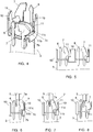
figure 4 is a perspective view of the proximal portion of the sleeve; -
figure 5 is a side view of this proximal portion; -
figures 6 to 8 are views of this proximal portion and a rib comprised by said body for locking the sleeve in three positions relative to said body; and -
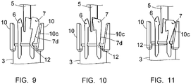
figures 9 to 11 are views similar tofigures 6 to 8 , respectively, of said proximal portion and said locking rib, according to a second embodiment of a locking leg comprised by this proximal portion, according to the present invention. - For simplification, the parts or elements of one embodiment which are found identically or similarly in another embodiment will be identified using the same numerical references and will not be described again.
-
Figures 2 and 3 illustrate adevice 1 for protecting an injection apparatus, in particular an injection apparatus for medical use, which, in the illustrated example, is a syringe. - The
device 1 comprises abody 2 in which are placed thesyringe body 100, asleeve 3 mobile in relation to thisbody 2, aspring 4 for moving thissleeve 3 in relation to thebody 2, and alocking assembly sleeve 3 in the illustrated position, called the "protective position". - In general, the device is very similar to that described in document N°
WO 2005/030301 , in the applicant's name, to which one may refer for more detailed explanations. - The
body 2 is tubular and has a length such that it can house thesyringe body 100, but that the needle of this syringe protrudes beyond the distal end of saidbody 2 when thesleeve 3 is in a "non-protective" position. In this position, thesleeve 3 is completely drawn into thebody 2, assuming a position between the wall of the latter and thesyringe body 100, and thespring 4, inserted between thesleeve 3 and a proximal ring which receives thebody 2, is stressed. - The
body 2 comprises two diametrically opposedribs 5, integral with said body and protruding inwardly, one of which is illustrated infigures 2 and 3 notwithstanding the longitudinal cross-section of thebody 2. Eachrib 5 comprises notched ends designed to cooperate with a pair ofproximal legs sleeve 3, in the same way as described in the aforementioned document N°WO 2005/030301 . In summary, in said non-protective position, theseproximal legs rib 5, and thereby ensure maintenance of thesleeve 3 in this position notwithstanding the elastic return force of thespring 4; at the end of injection, theselegs shaped projections 8 arranged on aproximal ring 9, itself moved by the piston rod of the syringe, such that they are unhooked from therib 5; thesleeve 3 thus being freed, thespring 4 relaxes and brings thissleeve 3 into the illustrated protective position, in which thesleeve 3 completely covers the needle of the syringe; among the twolegs leg 7 illustrated on the right infigures 2 and 3 slides along therib 5 and, when thesleeve 3 reaches said protective position, engages through elastic return in the distal notch formed by therib 5. A first bearingsurface 7a comprised by thisleg 7 at its proximal end then comes into the vicinity of a rim of therib 5 defining said distal notch, thereby locking thesleeve 3 in the protective position. - Besides the
legs sleeve 3 comprises, at its proximal part, as shown more particularly byfigures 3 to 5 ,fixed walls 10 adjacent to thelegs 7, which project in the proximal direction. - As appears by comparing
figures 1 on one hand and 2 to 5 on the other, it appears that eachleg 7 andadjacent wall 10 shown infigures 2 to 5 has a shape which differs from those of thecorresponding leg 7A and theprotruding wall 10A of the device according to the prior art illustrated infigure 1 . - Indeed, the
leg 7 illustrated infigures 2 to 5 has an enlarged upper portion, forming an extension in the circumferential direction, this extension having alower edge 7b which forms a first additional bearing surface and an end edge in thecircumferential direction 7c, which forms a second additional bearing surface. The bearing surface formed by theedge 7b is arranged substantially transversely in relation to the axis of thesleeve 3 and the bearing surface formed by theedge 7c is arranged substantially longitudinally in relation to the axis of thesleeve 3. These bearing surfaces are arranged substantially halfway up theleg 7. - The
adjacent wall 10 has, on its side adjacent to theleg 7, arectangular notch 11 forming arim 11 b which extends substantially in the transverse direction relative to the axis of sliding of thesleeve 3 and arim 11c which extends substantially in the longitudinal direction relative to the axis of sliding of thesleeve 3. - As appears in reference to
figures 6 to 8 , thenotch 11 enables engagement of theleg 7 in the distal notch of therib 5 notwithstanding the increased width of the proximal portion of this leg 7 (cf.figures 6 and 7 ). - When stress is exerted on the
sleeve 3 in the direction bringing thissleeve 3 back toward said non-protective position, theleg 7 tends to compress longitudinally. The respectiveadditional bearing surfaces figure 8 ), thesurfaces leg 7 according to the longitudinal direction of this leg and thesurfaces leg 7 according to the circumferential direction of thesleeve 3. Thesesurfaces leg 7 with the rest of thedevice 1 and therefore to better distribute the surface on which the stress undergone by theleg 7 is exerted during an attempt to force thesleeve 3 toward the non-protective position; moreover, the constraints of theleg 7 produced by these bearing surfaces take place at the median area of theleg 7, i.e. at the area of said leg most likely to undergo buckling. - As a result of the arrangement of these additional bearing surfaces, the
leg 7 has, relative to that of the device according to the prior art, greatly increased resistance, which makes it possible to effectively oppose forcing of thesleeve 3 toward the non-protective position. Moreover, within a same sample of a plurality ofdevices 1, the measured resistance to such forcing showed itself to be largely sufficient to obtain the desired protection in all cases. -
Figures 9 to 11 illustrate an embodiment of thedevice 1 according to the present invention, in which theleg 7 has, from the side of thewall 10, a rectilineartilted edge 7d extending over its entire length, while thewall 10 has, instead and in place of thenotch 11, a tiltedrectilinear edge 10c also extending over its entire length. - As shown in
figure 11 , upon an attempt to force thesleeve 3 toward the non-protective position, thetilted edge 7d realizes extended bearing against theedge 10c of thewall 10. The surface of this bearing increases as the intensity of the forcing increases. - In this other embodiment, the
leg 7 comprises anarea 12 having a reduced cross-section, located at its base, i.e. away from the additional bearing surfaces formed by theedges - This
area 12 makes it possible to increase the flexibility of theleg 7 in order to promote its engagement in the distal notch of therib 5; this flexibility also makes it possible to promote the mutual cooperation of saidadditional bearing surfaces leg 7 undergoes the stress generated by the action tending to return thesleeve 3 to the non-protective position. In particular, when it is necessary to provide for clearances between saidadditional bearing surfaces leg 7 in the distal notch of therib 5, thearea 12 may undergo compression in the longitudinal direction of theleg 7 ensuring the elimination of these clearances and therefore perfect mutual contact of thebearing surfaces - It appears from the preceding that the invention provides a device for protecting an injection apparatus, in particular an injection apparatus for medical use such as a syringe which, relative to the similar devices of the prior art, has determining advantages, described above.
- The invention has been described in reference to embodiments provided purely as examples. It goes without saying that it is not limited to these embodiments, but that it extends to all embodiments covered by the appended claims.
Claims (3)
- Device (1) for protecting an injection apparatus, in particular an injection apparatus for medical use such as a syringe, comprising a body (2) in which the injection apparatus is placed, a sleeve (3) mobile in relation to said body (2), means (4) for moving this sleeve (3) in relation to the body (2), and locking means (5, 6, 7) making it possible to lock the sleeve (3) in a protective position; the sleeve (3) can be moved between a non-protective position, in which an injection member comprised by the injection apparatus is exposed so as to allow injection, and said protective position, in which the sleeve (3) completely covers the injection member; said locking means (5, 6, 7) comprise at least one flexible proximal leg (7) integral with the sleeve (3), forming a first bearing surface (7a) through which said leg (7) engages, in said protective position, behind at least a first corresponding distal bearing surface arranged of said body (2); the flexible proximal leg (7) has a reduced thickness, such that it can assume a position between a body of the injection apparatus and the body (2) of the device (1);
the leg (7) comprises one additional bearing surface (7d) arranged thereon, and the device (1) comprises one corresponding additional bearing surface (10c), these respective additional bearing surfaces (7d, 10c) being able to bear against each other when a force is exerted on the sleeve (3) in the direction tending to return this sleeve (3) toward said non-protective position
characterized in that.- the leg (7) comprises a tilted edge (7d) extending over its entire length, forming said additional bearing surface comprised by said leg (7), and- the device comprises at least one wall (10) having a tilted rectilinear edge (10c) also extending over the entire length of this wall, forming said additional bearing surface (10c) of the device (1). - Device (1) according to claim 1, characterized in that said additional bearing surface (7d; 10c) of the leg (7) and the device (1) are arranged in a location located substantially between one-third and two-thirds of the length of the leg (7).
- Device (1) according to claim 1 or claim 2, characterized in that the leg (7) comprises an area (12) having a reduced cross-section, located away from said additional bearing surfaces.
Applications Claiming Priority (3)
| Application Number | Priority Date | Filing Date | Title |
|---|---|---|---|
| FR0800430A FR2926727B1 (en) | 2008-01-28 | 2008-01-28 | DEVICE FOR PROTECTING AN INJECTION APPARATUS, IN PARTICULAR A MEDICAL INJECTION APPARATUS SUCH AS A SERIGUE |
| PCT/IB2009/050134 WO2009095805A2 (en) | 2008-01-28 | 2009-01-14 | Device for protecting an injection apparatus, in particular an injection apparatus for medical use, such as a syringe |
| EP09705626.1A EP2237822B1 (en) | 2008-01-28 | 2009-01-14 | Device for protecting an injection apparatus, in particular an injection apparatus for medical use, such as a syringe |
Related Parent Applications (2)
| Application Number | Title | Priority Date | Filing Date |
|---|---|---|---|
| EP09705626.1A Division EP2237822B1 (en) | 2008-01-28 | 2009-01-14 | Device for protecting an injection apparatus, in particular an injection apparatus for medical use, such as a syringe |
| EP09705626.1A Division-Into EP2237822B1 (en) | 2008-01-28 | 2009-01-14 | Device for protecting an injection apparatus, in particular an injection apparatus for medical use, such as a syringe |
Publications (2)
| Publication Number | Publication Date |
|---|---|
| EP3241582A1 true EP3241582A1 (en) | 2017-11-08 |
| EP3241582B1 EP3241582B1 (en) | 2020-09-30 |
Family
ID=39301180
Family Applications (2)
| Application Number | Title | Priority Date | Filing Date |
|---|---|---|---|
| EP17171382.9A Active EP3241582B1 (en) | 2008-01-28 | 2009-01-14 | Device for protecting an injection apparatus, in particular an injection apparatus for medical use, such as a syringe |
| EP09705626.1A Active EP2237822B1 (en) | 2008-01-28 | 2009-01-14 | Device for protecting an injection apparatus, in particular an injection apparatus for medical use, such as a syringe |
Family Applications After (1)
| Application Number | Title | Priority Date | Filing Date |
|---|---|---|---|
| EP09705626.1A Active EP2237822B1 (en) | 2008-01-28 | 2009-01-14 | Device for protecting an injection apparatus, in particular an injection apparatus for medical use, such as a syringe |
Country Status (7)
| Country | Link |
|---|---|
| US (1) | US8900198B2 (en) |
| EP (2) | EP3241582B1 (en) |
| JP (1) | JP5475690B2 (en) |
| ES (2) | ES2637400T3 (en) |
| FR (1) | FR2926727B1 (en) |
| HU (1) | HUE037017T2 (en) |
| WO (1) | WO2009095805A2 (en) |
Families Citing this family (5)
| Publication number | Priority date | Publication date | Assignee | Title |
|---|---|---|---|---|
| US9233213B2 (en) | 2009-10-16 | 2016-01-12 | Janssen Biotech, Inc. | Palm activated drug delivery device |
| NZ705415A (en) | 2009-10-16 | 2016-01-29 | Janssen Biotech Inc | Palm activated drug delivery device |
| WO2012000836A1 (en) | 2010-07-02 | 2012-01-05 | Sanofi-Aventis Deutschland Gmbh | Safety device for a pre-filled syringe and injection device |
| USD731051S1 (en) | 2013-03-15 | 2015-06-02 | Janssen Biotech, Inc. | Drug delivery device |
| EP2784766A1 (en) | 2013-03-28 | 2014-10-01 | F. Hoffmann-La Roche AG | Training device for medicine injection devices and reset device for resetting such a training device |
Citations (6)
| Publication number | Priority date | Publication date | Assignee | Title |
|---|---|---|---|---|
| WO1999017823A1 (en) | 1997-10-02 | 1999-04-15 | Safety Syringes, Inc. | Disposable self-shielding unit dose syringe guard |
| WO2001085239A2 (en) | 2000-05-05 | 2001-11-15 | Safety Syringes, Inc. | Passive needle guard for syringes |
| WO2002083205A1 (en) | 2001-04-13 | 2002-10-24 | Becton Dickinson And Company, Inc. | Prefillable intradermal delivery device with hidden needle and passive shielding |
| WO2002098494A2 (en) * | 2001-06-07 | 2002-12-12 | Becton, Dickinson And Company | Safety shield system for prefilled syringes |
| WO2003013632A2 (en) | 2001-08-10 | 2003-02-20 | Owen Mumford Limited | Protective shroud for injection devices |
| WO2005030301A1 (en) | 2003-09-26 | 2005-04-07 | Becton Dickinson France | Device for protecting an injection device |
Family Cites Families (1)
| Publication number | Priority date | Publication date | Assignee | Title |
|---|---|---|---|---|
| US20050033230A1 (en) * | 2002-02-15 | 2005-02-10 | Alchas Paul G. | Prefillable intradermal delivery device with hidden needle and passive shielding |
-
2008
- 2008-01-28 FR FR0800430A patent/FR2926727B1/en active Active
-
2009
- 2009-01-14 ES ES09705626.1T patent/ES2637400T3/en active Active
- 2009-01-14 HU HUE09705626A patent/HUE037017T2/en unknown
- 2009-01-14 WO PCT/IB2009/050134 patent/WO2009095805A2/en not_active Ceased
- 2009-01-14 ES ES17171382T patent/ES2829276T3/en active Active
- 2009-01-14 EP EP17171382.9A patent/EP3241582B1/en active Active
- 2009-01-14 US US12/864,974 patent/US8900198B2/en active Active
- 2009-01-14 EP EP09705626.1A patent/EP2237822B1/en active Active
- 2009-01-14 JP JP2010544820A patent/JP5475690B2/en active Active
Patent Citations (6)
| Publication number | Priority date | Publication date | Assignee | Title |
|---|---|---|---|---|
| WO1999017823A1 (en) | 1997-10-02 | 1999-04-15 | Safety Syringes, Inc. | Disposable self-shielding unit dose syringe guard |
| WO2001085239A2 (en) | 2000-05-05 | 2001-11-15 | Safety Syringes, Inc. | Passive needle guard for syringes |
| WO2002083205A1 (en) | 2001-04-13 | 2002-10-24 | Becton Dickinson And Company, Inc. | Prefillable intradermal delivery device with hidden needle and passive shielding |
| WO2002098494A2 (en) * | 2001-06-07 | 2002-12-12 | Becton, Dickinson And Company | Safety shield system for prefilled syringes |
| WO2003013632A2 (en) | 2001-08-10 | 2003-02-20 | Owen Mumford Limited | Protective shroud for injection devices |
| WO2005030301A1 (en) | 2003-09-26 | 2005-04-07 | Becton Dickinson France | Device for protecting an injection device |
Also Published As
| Publication number | Publication date |
|---|---|
| FR2926727A1 (en) | 2009-07-31 |
| EP2237822A2 (en) | 2010-10-13 |
| WO2009095805A2 (en) | 2009-08-06 |
| ES2637400T3 (en) | 2017-10-13 |
| EP3241582B1 (en) | 2020-09-30 |
| JP2011510731A (en) | 2011-04-07 |
| FR2926727B1 (en) | 2010-12-24 |
| WO2009095805A3 (en) | 2010-10-28 |
| JP5475690B2 (en) | 2014-04-16 |
| US20110034880A1 (en) | 2011-02-10 |
| ES2829276T3 (en) | 2021-05-31 |
| EP2237822B1 (en) | 2017-08-02 |
| HUE037017T2 (en) | 2018-08-28 |
| US8900198B2 (en) | 2014-12-02 |
Similar Documents
| Publication | Publication Date | Title |
|---|---|---|
| EP3241582B1 (en) | Device for protecting an injection apparatus, in particular an injection apparatus for medical use, such as a syringe | |
| KR102330275B1 (en) | A shaving blade cartridge and a shaver comprising such shaving blade cartridge | |
| DK2776110T3 (en) | Intravenous catheter device | |
| US8801663B2 (en) | Protective device for an injection needle | |
| WO2014003632A1 (en) | Protective cover for disposable injection needles | |
| EP1693007A3 (en) | Surgical staple | |
| JP2006500172A5 (en) | ||
| US20110209309A1 (en) | Clip for holding two parts together | |
| EP4393416A3 (en) | Surgical clip | |
| CN107107862A (en) | Dead bolt with torsion bar | |
| ATE458449T1 (en) | SPINAL SUPPORT ROD KIT | |
| US20030042831A1 (en) | Jacket for use with a lock latch, a lock latch incorporating the same and a slide incorporating the lock latch and jacket | |
| EP2605937A1 (en) | Device for retaining an attached part on a carrier part and arrangement having such a device and having an attached part | |
| KR20200086308A (en) | Support structure | |
| CN108367448A (en) | Razor head | |
| WO2007053960A8 (en) | Intramedullary, longitudinal implant | |
| EP2837555A1 (en) | Variable-length rail cover for a seat rail | |
| US8016602B2 (en) | Multicontact connector with an incorporated rotary locking part | |
| US20040067095A1 (en) | Pin stop for mechanical joints | |
| EP3024514A1 (en) | Butterfly needle with a protective device | |
| US20150126905A1 (en) | Safety sleeve syringe | |
| US11660080B2 (en) | Biopsy gun | |
| US10617922B2 (en) | Adjustment device for use with athletic equipment | |
| ATE454056T1 (en) | CUFFLINK | |
| DE102022101096A1 (en) | Household appliance and pull-out guide for a household appliance |
Legal Events
| Date | Code | Title | Description |
|---|---|---|---|
| PUAI | Public reference made under article 153(3) epc to a published international application that has entered the european phase |
Free format text: ORIGINAL CODE: 0009012 |
|
| STAA | Information on the status of an ep patent application or granted ep patent |
Free format text: STATUS: THE APPLICATION HAS BEEN PUBLISHED |
|
| AC | Divisional application: reference to earlier application |
Ref document number: 2237822 Country of ref document: EP Kind code of ref document: P |
|
| AK | Designated contracting states |
Kind code of ref document: A1 Designated state(s): AT BE BG CH CY CZ DE DK EE ES FI FR GB GR HR HU IE IS IT LI LT LU LV MC MK MT NL NO PL PT RO SE SI SK TR |
|
| STAA | Information on the status of an ep patent application or granted ep patent |
Free format text: STATUS: REQUEST FOR EXAMINATION WAS MADE |
|
| 17P | Request for examination filed |
Effective date: 20180108 |
|
| RBV | Designated contracting states (corrected) |
Designated state(s): AT BE BG CH CY CZ DE DK EE ES FI FR GB GR HR HU IE IS IT LI LT LU LV MC MK MT NL NO PL PT RO SE SI SK TR |
|
| STAA | Information on the status of an ep patent application or granted ep patent |
Free format text: STATUS: EXAMINATION IS IN PROGRESS |
|
| 17Q | First examination report despatched |
Effective date: 20181001 |
|
| GRAP | Despatch of communication of intention to grant a patent |
Free format text: ORIGINAL CODE: EPIDOSNIGR1 |
|
| STAA | Information on the status of an ep patent application or granted ep patent |
Free format text: STATUS: GRANT OF PATENT IS INTENDED |
|
| INTG | Intention to grant announced |
Effective date: 20200604 |
|
| GRAS | Grant fee paid |
Free format text: ORIGINAL CODE: EPIDOSNIGR3 |
|
| GRAA | (expected) grant |
Free format text: ORIGINAL CODE: 0009210 |
|
| STAA | Information on the status of an ep patent application or granted ep patent |
Free format text: STATUS: THE PATENT HAS BEEN GRANTED |
|
| AC | Divisional application: reference to earlier application |
Ref document number: 2237822 Country of ref document: EP Kind code of ref document: P |
|
| AK | Designated contracting states |
Kind code of ref document: B1 Designated state(s): AT BE BG CH CY CZ DE DK EE ES FI FR GB GR HR HU IE IS IT LI LT LU LV MC MK MT NL NO PL PT RO SE SI SK TR |
|
| REG | Reference to a national code |
Ref country code: GB Ref legal event code: FG4D Ref country code: CH Ref legal event code: EP |
|
| REG | Reference to a national code |
Ref country code: AT Ref legal event code: REF Ref document number: 1318150 Country of ref document: AT Kind code of ref document: T Effective date: 20201015 Ref country code: DE Ref legal event code: R096 Ref document number: 602009062868 Country of ref document: DE |
|
| REG | Reference to a national code |
Ref country code: IE Ref legal event code: FG4D |
|
| PG25 | Lapsed in a contracting state [announced via postgrant information from national office to epo] |
Ref country code: BG Free format text: LAPSE BECAUSE OF FAILURE TO SUBMIT A TRANSLATION OF THE DESCRIPTION OR TO PAY THE FEE WITHIN THE PRESCRIBED TIME-LIMIT Effective date: 20201230 Ref country code: HR Free format text: LAPSE BECAUSE OF FAILURE TO SUBMIT A TRANSLATION OF THE DESCRIPTION OR TO PAY THE FEE WITHIN THE PRESCRIBED TIME-LIMIT Effective date: 20200930 Ref country code: FI Free format text: LAPSE BECAUSE OF FAILURE TO SUBMIT A TRANSLATION OF THE DESCRIPTION OR TO PAY THE FEE WITHIN THE PRESCRIBED TIME-LIMIT Effective date: 20200930 Ref country code: GR Free format text: LAPSE BECAUSE OF FAILURE TO SUBMIT A TRANSLATION OF THE DESCRIPTION OR TO PAY THE FEE WITHIN THE PRESCRIBED TIME-LIMIT Effective date: 20201231 Ref country code: SE Free format text: LAPSE BECAUSE OF FAILURE TO SUBMIT A TRANSLATION OF THE DESCRIPTION OR TO PAY THE FEE WITHIN THE PRESCRIBED TIME-LIMIT Effective date: 20200930 Ref country code: NO Free format text: LAPSE BECAUSE OF FAILURE TO SUBMIT A TRANSLATION OF THE DESCRIPTION OR TO PAY THE FEE WITHIN THE PRESCRIBED TIME-LIMIT Effective date: 20201230 |
|
| REG | Reference to a national code |
Ref country code: AT Ref legal event code: MK05 Ref document number: 1318150 Country of ref document: AT Kind code of ref document: T Effective date: 20200930 |
|
| PG25 | Lapsed in a contracting state [announced via postgrant information from national office to epo] |
Ref country code: LV Free format text: LAPSE BECAUSE OF FAILURE TO SUBMIT A TRANSLATION OF THE DESCRIPTION OR TO PAY THE FEE WITHIN THE PRESCRIBED TIME-LIMIT Effective date: 20200930 |
|
| REG | Reference to a national code |
Ref country code: NL Ref legal event code: MP Effective date: 20200930 |
|
| REG | Reference to a national code |
Ref country code: LT Ref legal event code: MG4D |
|
| PG25 | Lapsed in a contracting state [announced via postgrant information from national office to epo] |
Ref country code: LT Free format text: LAPSE BECAUSE OF FAILURE TO SUBMIT A TRANSLATION OF THE DESCRIPTION OR TO PAY THE FEE WITHIN THE PRESCRIBED TIME-LIMIT Effective date: 20200930 Ref country code: NL Free format text: LAPSE BECAUSE OF FAILURE TO SUBMIT A TRANSLATION OF THE DESCRIPTION OR TO PAY THE FEE WITHIN THE PRESCRIBED TIME-LIMIT Effective date: 20200930 Ref country code: CZ Free format text: LAPSE BECAUSE OF FAILURE TO SUBMIT A TRANSLATION OF THE DESCRIPTION OR TO PAY THE FEE WITHIN THE PRESCRIBED TIME-LIMIT Effective date: 20200930 Ref country code: PT Free format text: LAPSE BECAUSE OF FAILURE TO SUBMIT A TRANSLATION OF THE DESCRIPTION OR TO PAY THE FEE WITHIN THE PRESCRIBED TIME-LIMIT Effective date: 20210201 Ref country code: RO Free format text: LAPSE BECAUSE OF FAILURE TO SUBMIT A TRANSLATION OF THE DESCRIPTION OR TO PAY THE FEE WITHIN THE PRESCRIBED TIME-LIMIT Effective date: 20200930 Ref country code: EE Free format text: LAPSE BECAUSE OF FAILURE TO SUBMIT A TRANSLATION OF THE DESCRIPTION OR TO PAY THE FEE WITHIN THE PRESCRIBED TIME-LIMIT Effective date: 20200930 |
|
| PG25 | Lapsed in a contracting state [announced via postgrant information from national office to epo] |
Ref country code: IS Free format text: LAPSE BECAUSE OF FAILURE TO SUBMIT A TRANSLATION OF THE DESCRIPTION OR TO PAY THE FEE WITHIN THE PRESCRIBED TIME-LIMIT Effective date: 20210130 Ref country code: PL Free format text: LAPSE BECAUSE OF FAILURE TO SUBMIT A TRANSLATION OF THE DESCRIPTION OR TO PAY THE FEE WITHIN THE PRESCRIBED TIME-LIMIT Effective date: 20200930 Ref country code: AT Free format text: LAPSE BECAUSE OF FAILURE TO SUBMIT A TRANSLATION OF THE DESCRIPTION OR TO PAY THE FEE WITHIN THE PRESCRIBED TIME-LIMIT Effective date: 20200930 |
|
| REG | Reference to a national code |
Ref country code: ES Ref legal event code: FG2A Ref document number: 2829276 Country of ref document: ES Kind code of ref document: T3 Effective date: 20210531 |
|
| PG25 | Lapsed in a contracting state [announced via postgrant information from national office to epo] |
Ref country code: SK Free format text: LAPSE BECAUSE OF FAILURE TO SUBMIT A TRANSLATION OF THE DESCRIPTION OR TO PAY THE FEE WITHIN THE PRESCRIBED TIME-LIMIT Effective date: 20200930 |
|
| REG | Reference to a national code |
Ref country code: DE Ref legal event code: R097 Ref document number: 602009062868 Country of ref document: DE |
|
| PLBE | No opposition filed within time limit |
Free format text: ORIGINAL CODE: 0009261 |
|
| STAA | Information on the status of an ep patent application or granted ep patent |
Free format text: STATUS: NO OPPOSITION FILED WITHIN TIME LIMIT |
|
| PG25 | Lapsed in a contracting state [announced via postgrant information from national office to epo] |
Ref country code: DK Free format text: LAPSE BECAUSE OF FAILURE TO SUBMIT A TRANSLATION OF THE DESCRIPTION OR TO PAY THE FEE WITHIN THE PRESCRIBED TIME-LIMIT Effective date: 20200930 Ref country code: MC Free format text: LAPSE BECAUSE OF FAILURE TO SUBMIT A TRANSLATION OF THE DESCRIPTION OR TO PAY THE FEE WITHIN THE PRESCRIBED TIME-LIMIT Effective date: 20200930 |
|
| REG | Reference to a national code |
Ref country code: CH Ref legal event code: PL |
|
| 26N | No opposition filed |
Effective date: 20210701 |
|
| PG25 | Lapsed in a contracting state [announced via postgrant information from national office to epo] |
Ref country code: LU Free format text: LAPSE BECAUSE OF NON-PAYMENT OF DUE FEES Effective date: 20210114 |
|
| REG | Reference to a national code |
Ref country code: BE Ref legal event code: MM Effective date: 20210131 |
|
| PG25 | Lapsed in a contracting state [announced via postgrant information from national office to epo] |
Ref country code: LI Free format text: LAPSE BECAUSE OF NON-PAYMENT OF DUE FEES Effective date: 20210131 Ref country code: SI Free format text: LAPSE BECAUSE OF FAILURE TO SUBMIT A TRANSLATION OF THE DESCRIPTION OR TO PAY THE FEE WITHIN THE PRESCRIBED TIME-LIMIT Effective date: 20200930 Ref country code: CH Free format text: LAPSE BECAUSE OF NON-PAYMENT OF DUE FEES Effective date: 20210131 |
|
| PG25 | Lapsed in a contracting state [announced via postgrant information from national office to epo] |
Ref country code: IE Free format text: LAPSE BECAUSE OF NON-PAYMENT OF DUE FEES Effective date: 20210114 |
|
| PG25 | Lapsed in a contracting state [announced via postgrant information from national office to epo] |
Ref country code: IS Free format text: LAPSE BECAUSE OF FAILURE TO SUBMIT A TRANSLATION OF THE DESCRIPTION OR TO PAY THE FEE WITHIN THE PRESCRIBED TIME-LIMIT Effective date: 20210130 |
|
| PG25 | Lapsed in a contracting state [announced via postgrant information from national office to epo] |
Ref country code: BE Free format text: LAPSE BECAUSE OF NON-PAYMENT OF DUE FEES Effective date: 20210131 |
|
| PG25 | Lapsed in a contracting state [announced via postgrant information from national office to epo] |
Ref country code: HU Free format text: LAPSE BECAUSE OF FAILURE TO SUBMIT A TRANSLATION OF THE DESCRIPTION OR TO PAY THE FEE WITHIN THE PRESCRIBED TIME-LIMIT; INVALID AB INITIO Effective date: 20090114 Ref country code: CY Free format text: LAPSE BECAUSE OF FAILURE TO SUBMIT A TRANSLATION OF THE DESCRIPTION OR TO PAY THE FEE WITHIN THE PRESCRIBED TIME-LIMIT Effective date: 20200930 |
|
| PG25 | Lapsed in a contracting state [announced via postgrant information from national office to epo] |
Ref country code: MK Free format text: LAPSE BECAUSE OF FAILURE TO SUBMIT A TRANSLATION OF THE DESCRIPTION OR TO PAY THE FEE WITHIN THE PRESCRIBED TIME-LIMIT Effective date: 20200930 |
|
| PG25 | Lapsed in a contracting state [announced via postgrant information from national office to epo] |
Ref country code: TR Free format text: LAPSE BECAUSE OF FAILURE TO SUBMIT A TRANSLATION OF THE DESCRIPTION OR TO PAY THE FEE WITHIN THE PRESCRIBED TIME-LIMIT Effective date: 20200930 |
|
| PG25 | Lapsed in a contracting state [announced via postgrant information from national office to epo] |
Ref country code: MT Free format text: LAPSE BECAUSE OF FAILURE TO SUBMIT A TRANSLATION OF THE DESCRIPTION OR TO PAY THE FEE WITHIN THE PRESCRIBED TIME-LIMIT Effective date: 20200930 |
|
| PGFP | Annual fee paid to national office [announced via postgrant information from national office to epo] |
Ref country code: GB Payment date: 20251220 Year of fee payment: 18 |
|
| PGFP | Annual fee paid to national office [announced via postgrant information from national office to epo] |
Ref country code: FR Payment date: 20251217 Year of fee payment: 18 |
|
| PGFP | Annual fee paid to national office [announced via postgrant information from national office to epo] |
Ref country code: ES Payment date: 20260202 Year of fee payment: 18 |
|
| PGFP | Annual fee paid to national office [announced via postgrant information from national office to epo] |
Ref country code: DE Payment date: 20251217 Year of fee payment: 18 |
|
| PGFP | Annual fee paid to national office [announced via postgrant information from national office to epo] |
Ref country code: IT Payment date: 20260107 Year of fee payment: 18 |