EP3241513A1 - Current sensor with reduced voltage coupling - Google Patents
Current sensor with reduced voltage coupling Download PDFInfo
- Publication number
- EP3241513A1 EP3241513A1 EP17168928.4A EP17168928A EP3241513A1 EP 3241513 A1 EP3241513 A1 EP 3241513A1 EP 17168928 A EP17168928 A EP 17168928A EP 3241513 A1 EP3241513 A1 EP 3241513A1
- Authority
- EP
- European Patent Office
- Prior art keywords
- outer coil
- current
- coil
- lead
- coupled
- Prior art date
- Legal status (The legal status is an assumption and is not a legal conclusion. Google has not performed a legal analysis and makes no representation as to the accuracy of the status listed.)
- Granted
Links
- 230000008878 coupling Effects 0.000 title claims description 7
- 238000010168 coupling process Methods 0.000 title claims description 7
- 238000005859 coupling reaction Methods 0.000 title claims description 7
- 239000004020 conductor Substances 0.000 claims abstract description 47
- 230000005684 electric field Effects 0.000 claims abstract description 17
- 230000003750 conditioning effect Effects 0.000 claims description 14
- 238000000034 method Methods 0.000 description 5
- 238000007789 sealing Methods 0.000 description 5
- 238000010586 diagram Methods 0.000 description 3
- 238000002955 isolation Methods 0.000 description 3
- 238000005259 measurement Methods 0.000 description 3
- 238000004804 winding Methods 0.000 description 3
- 238000002679 ablation Methods 0.000 description 2
- 238000005520 cutting process Methods 0.000 description 2
- 230000000694 effects Effects 0.000 description 2
- 230000006870 function Effects 0.000 description 2
- 230000008569 process Effects 0.000 description 2
- 0 CCCC1C(N=O)=C(CC**CCN)CC1 Chemical compound CCCC1C(N=O)=C(CC**CCN)CC1 0.000 description 1
- 239000012190 activator Substances 0.000 description 1
- 239000011230 binding agent Substances 0.000 description 1
- 239000003990 capacitor Substances 0.000 description 1
- 230000015271 coagulation Effects 0.000 description 1
- 238000005345 coagulation Methods 0.000 description 1
- 239000002131 composite material Substances 0.000 description 1
- 238000010276 construction Methods 0.000 description 1
- 238000013461 design Methods 0.000 description 1
- 239000003989 dielectric material Substances 0.000 description 1
- 239000003822 epoxy resin Substances 0.000 description 1
- 239000004744 fabric Substances 0.000 description 1
- 239000011152 fibreglass Substances 0.000 description 1
- 230000023597 hemostasis Effects 0.000 description 1
- 239000000203 mixture Substances 0.000 description 1
- 238000012986 modification Methods 0.000 description 1
- 230000004048 modification Effects 0.000 description 1
- 238000012544 monitoring process Methods 0.000 description 1
- 230000003287 optical effect Effects 0.000 description 1
- 230000035699 permeability Effects 0.000 description 1
- 229920000647 polyepoxide Polymers 0.000 description 1
- 238000012545 processing Methods 0.000 description 1
- 230000003362 replicative effect Effects 0.000 description 1
- 239000000523 sample Substances 0.000 description 1
- 239000007921 spray Substances 0.000 description 1
- 230000000451 tissue damage Effects 0.000 description 1
- 231100000827 tissue damage Toxicity 0.000 description 1
Images




Classifications
-
- G—PHYSICS
- G01—MEASURING; TESTING
- G01R—MEASURING ELECTRIC VARIABLES; MEASURING MAGNETIC VARIABLES
- G01R15/00—Details of measuring arrangements of the types provided for in groups G01R17/00 - G01R29/00, G01R33/00 - G01R33/26 or G01R35/00
- G01R15/14—Adaptations providing voltage or current isolation, e.g. for high-voltage or high-current networks
- G01R15/18—Adaptations providing voltage or current isolation, e.g. for high-voltage or high-current networks using inductive devices, e.g. transformers
- G01R15/183—Adaptations providing voltage or current isolation, e.g. for high-voltage or high-current networks using inductive devices, e.g. transformers using transformers with a magnetic core
- G01R15/185—Adaptations providing voltage or current isolation, e.g. for high-voltage or high-current networks using inductive devices, e.g. transformers using transformers with a magnetic core with compensation or feedback windings or interacting coils, e.g. 0-flux sensors
-
- A—HUMAN NECESSITIES
- A61—MEDICAL OR VETERINARY SCIENCE; HYGIENE
- A61B—DIAGNOSIS; SURGERY; IDENTIFICATION
- A61B18/00—Surgical instruments, devices or methods for transferring non-mechanical forms of energy to or from the body
- A61B18/04—Surgical instruments, devices or methods for transferring non-mechanical forms of energy to or from the body by heating
- A61B18/12—Surgical instruments, devices or methods for transferring non-mechanical forms of energy to or from the body by heating by passing a current through the tissue to be heated, e.g. high-frequency current
- A61B18/1206—Generators therefor
-
- G—PHYSICS
- G01—MEASURING; TESTING
- G01R—MEASURING ELECTRIC VARIABLES; MEASURING MAGNETIC VARIABLES
- G01R15/00—Details of measuring arrangements of the types provided for in groups G01R17/00 - G01R29/00, G01R33/00 - G01R33/26 or G01R35/00
- G01R15/14—Adaptations providing voltage or current isolation, e.g. for high-voltage or high-current networks
- G01R15/18—Adaptations providing voltage or current isolation, e.g. for high-voltage or high-current networks using inductive devices, e.g. transformers
- G01R15/181—Adaptations providing voltage or current isolation, e.g. for high-voltage or high-current networks using inductive devices, e.g. transformers using coils without a magnetic core, e.g. Rogowski coils
-
- A—HUMAN NECESSITIES
- A61—MEDICAL OR VETERINARY SCIENCE; HYGIENE
- A61B—DIAGNOSIS; SURGERY; IDENTIFICATION
- A61B18/00—Surgical instruments, devices or methods for transferring non-mechanical forms of energy to or from the body
- A61B2018/00053—Mechanical features of the instrument of device
- A61B2018/00172—Connectors and adapters therefor
- A61B2018/00178—Electrical connectors
-
- A—HUMAN NECESSITIES
- A61—MEDICAL OR VETERINARY SCIENCE; HYGIENE
- A61B—DIAGNOSIS; SURGERY; IDENTIFICATION
- A61B18/00—Surgical instruments, devices or methods for transferring non-mechanical forms of energy to or from the body
- A61B2018/00636—Sensing and controlling the application of energy
- A61B2018/00773—Sensed parameters
- A61B2018/00827—Current
-
- A—HUMAN NECESSITIES
- A61—MEDICAL OR VETERINARY SCIENCE; HYGIENE
- A61B—DIAGNOSIS; SURGERY; IDENTIFICATION
- A61B18/00—Surgical instruments, devices or methods for transferring non-mechanical forms of energy to or from the body
- A61B2018/00636—Sensing and controlling the application of energy
- A61B2018/00773—Sensed parameters
- A61B2018/00827—Current
- A61B2018/00833—Differential current
-
- A—HUMAN NECESSITIES
- A61—MEDICAL OR VETERINARY SCIENCE; HYGIENE
- A61B—DIAGNOSIS; SURGERY; IDENTIFICATION
- A61B18/00—Surgical instruments, devices or methods for transferring non-mechanical forms of energy to or from the body
- A61B18/04—Surgical instruments, devices or methods for transferring non-mechanical forms of energy to or from the body by heating
- A61B18/12—Surgical instruments, devices or methods for transferring non-mechanical forms of energy to or from the body by heating by passing a current through the tissue to be heated, e.g. high-frequency current
- A61B18/1206—Generators therefor
- A61B2018/1286—Generators therefor having a specific transformer
-
- G—PHYSICS
- G01—MEASURING; TESTING
- G01R—MEASURING ELECTRIC VARIABLES; MEASURING MAGNETIC VARIABLES
- G01R1/00—Details of instruments or arrangements of the types included in groups G01R5/00 - G01R13/00 and G01R31/00
- G01R1/02—General constructional details
- G01R1/06—Measuring leads; Measuring probes
- G01R1/067—Measuring probes
- G01R1/06788—Hand-held or hand-manipulated probes, e.g. for oscilloscopes or for portable test instruments
Definitions
- the present disclosure relates to a current sensor for use with an electrosurgical generator configured to generate a radio frequency ("RF") waveform.
- RF radio frequency
- the present disclosure relates to a current sense coil configured to eliminate and/or minimize effects of external voltage coupling.
- Electrosurgery involves application of high radio frequency electrical current to a surgical site to cut, ablate, desiccate, or coagulate tissue.
- a source or active electrode delivers RF alternating current from the electrosurgical generator to the targeted tissue.
- a patient return electrode is placed remotely from the active electrode to conduct the current back to the generator.
- bipolar electrosurgery In bipolar electrosurgery, return and active electrodes are placed in close proximity to each other such that an electrical circuit is formed between the two electrodes (e.g., in the case of an electrosurgical forceps). In this manner, the applied electrical current is limited to the body tissue positioned between the electrodes. Accordingly, bipolar electrosurgery generally involves the use of instruments where it is desired to achieve a focused delivery of electrosurgical energy between two electrodes.
- a current sensor includes a current sense coil disposed about a conductive lead, the current sense coil configured to sense a current passing through the conductive lead.
- the current sense coil includes: a first outer coil configured to detect a first magnetic field generated by the current; a second outer coil configured to detect the first magnetic field, the second outer coil further configured to cancel an electrical field induced in the first outer coil; and an inner conductor disposed between the first outer coil and the second outer coil, the inner conductor configured to detect a second magnetic field generated by the current.
- an electrosurgical generator includes: a power supply configured to output a direct current; a power converter coupled to the power supply, the power converter configured to generate a radio frequency current based on the direct current; at least one lead coupling the power converter to a terminal configured to couple to an electrosurgical instrument; and a current sensor.
- the current sensor includes: a current sense coil disposed about the at least one lead, the current sense coil configured to sense the radio frequency current passing through the at least one lead.
- the current sense coil includes: a first outer coil configured to detect a first magnetic field generated by the radio frequency current; a second outer coil configured to detect the first magnetic field, the second outer coil further configured to cancel an electrical field induced in the first outer coil; and an inner conductor disposed between the first outer coil and the second outer coil, the inner conductor configured to detect a second magnetic field generated by the radio frequency current.
- each of the first outer coil and the second outer coil includes a first balancing portion and a second balancing potion.
- the first balancing portion of the first outer coil and the second balancing portion of the second outer coil are coupled to a first lead.
- the second balancing portion of the first outer coil and the first balancing portion of the second outer coil are coupled to a second lead.
- the current sensor further includes a conditioning circuit coupled to the first lead and the second lead.
- each of the first outer coil and the second outer coil are coupled to the inner conductor.
- the current sensor further includes a printed circuit board having a plurality of dielectric layers.
- each of the first outer coil, the second outer coil, and the inner conductor are disposed on a corresponding dielectric layer of the plurality of dielectric layers.
- an electrosurgical generator may be used in monopolar and/or bipolar electrosurgical procedures, including, for example, cutting, coagulation, ablation, and vessel sealing procedures.
- the generator may include a plurality of outputs for interfacing with various electrosurgical instruments (e.g., monopolar instruments, return electrode pads, bipolar electrosurgical forceps, footswitches, etc.).
- the generator may include electronic circuitry configured to generate radio frequency energy specifically suited for powering electrosurgical devices operating in various electrosurgical modes (e.g., cut, blend, coagulate, division with hemostasis, fulgurate, spray, etc.) and procedures (e.g., monopolar, bipolar, vessel sealing).
- an electrosurgical system 10 includes one or more monopolar electrosurgical instruments 20 having one or more active electrodes 23 (e.g., electrosurgical cutting probe, ablation electrode(s), etc.) for treating tissue of a patient.
- Electrosurgical alternating RF current is supplied to the instrument 20 by a generator 200 via a supply line 24 that is connected to an active terminal 350 ( FIG. 3 ) of the generator 200, allowing the instrument 20 to cut, coagulate, and/or otherwise treat tissue.
- the RF current is returned to the generator 200 through a return electrode pad 26 via a return line 28 at a return terminal 352 ( FIG. 3 ) of the generator 200.
- the system 10 may include a plurality of return electrode pads 26 that, in use, are disposed on a patient to minimize the chances of tissue damage by maximizing the overall contact area with the patient.
- the generator 200 and the return electrode pads 26 may be configured for monitoring tissue-to-patient contact to ensure that sufficient contact exists therebetween.
- the system 10 may also include one or more bipolar electrosurgical instruments, for example, a bipolar electrosurgical forceps 30 having one or more electrodes for treating tissue of a patient.
- the electrosurgical forceps 30 includes a housing 31 and opposing jaw members 33 and 35 disposed at a distal end of a shaft 32.
- the jaw members 33 and 35 have one or more active electrodes 34 and a return electrode 36 disposed therein, respectively.
- the active electrode 34 and the return electrode 36 are connected to the generator 200 through cable 38 that includes the supply and return lines 24, 28, which may be coupled to the active and return terminals 350, 352, respectively ( FIG. 3 ).
- the electrosurgical forceps 30 is coupled to the generator 200 at a port having connections to the active and return terminals 350 and 352 (e.g., pins) via a plug disposed at the end of the cable 38, wherein the plug includes contacts from the supply and return lines 24, 28 as described in more detail below.
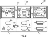
- the generator 200 may include a plurality of ports 250-262 to accommodate various types of electrosurgical instruments (e.g., monopolar electrosurgical instrument 20, electrosurgical forceps 30, etc.).
- electrosurgical instruments e.g., monopolar electrosurgical instrument 20, electrosurgical forceps 30, etc.
- the generator 200 includes a user interface 241 having one or more display screens 242, 244, 246 for providing the user with variety of output information (e.g., intensity settings, treatment complete indicators, etc.). Each of the screens 242, 244, 246 is associated with a corresponding port 250-262.
- the generator 200 includes suitable input controls (e.g., buttons, activators, switches, touch screen, etc.) for controlling the generator 200.
- the screens 242, 244, 246 are also configured as touch screens that display a corresponding menu for the instruments (e.g., electrosurgical forceps 30, etc.). The user may adjust inputs by simply touching corresponding menu options.
- Screen 242 controls monopolar output and the devices connected to the ports 250 and 252.
- Port 250 is configured to couple to a monopolar electrosurgical instrument (e.g., electrosurgical instrument 20) and port 252 is configured to couple to a foot switch (not shown). The foot switch provides for additional inputs (e.g., replicating inputs of the generator 200).
- the port 254 is configured to couple to the return electrode pad 26.
- Screen 244 controls monopolar and bipolar output and the devices connected to the ports 256 and 258.
- Port 256 is configured to couple to other monopolar instruments.
- Port 258 is configured to couple to a bipolar instrument (not shown).
- Screen 246 controls the electrosurgical forceps 30 that may be plugged into one of the ports 260 and 262, respectively.
- the generator 200 outputs energy through the ports 260 and 262 suitable for sealing tissue grasped by the electrosurgical forceps 30.
- screen 246 outputs a user interface that allows the user to input a user-defined intensity setting for each of the ports 260 and 262.
- the user-defined setting may be any setting that allows the user to adjust one or more energy delivery parameters, such as power, current, voltage, energy, etc. or sealing parameters, such as energy rate limiters, sealing duration, etc.
- the user-defined setting is transmitted to a controller 324 ( FIG. 3 ) where the setting may be saved in memory.
- the intensity setting may be a number scale, such as for example, from one to ten or one to five. In embodiments, the intensity setting may be associated with an output curve of the generator 200.
- the intensity settings may be specific for each electrosurgical forceps 30 being utilized, such that various instruments provide the user with a specific intensity scale corresponding to the electrosurgical forceps 30.
- the active and return terminals 350 and 352 may be coupled to any of the desired ports 250-262.
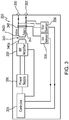
- the generator 200 also includes a controller 324, a power supply 326, and a power converter 332.
- the power supply 326 may be a high voltage, DC power supply connected to an AC source (e.g., line voltage) and provides high voltage, DC power to the power converter 332, which then converts high voltage, DC power into RF energy and delivers the energy to the active terminal 350. The energy is returned thereto via the return terminal 352.
- electrosurgical energy for energizing the monopolar electrosurgical instrument 20 and/or electrosurgical forceps 30 is delivered through the active and return terminals 350 and 352.
- the active and return terminals 350 and 352 are coupled to the power converter 332 through an isolation transformer 340.
- the isolation transformer 340 includes a primary winding 340a coupled to the power converter 332 and a secondary winding 340b having an active lead 342 coupled to the active terminal 350 and a return lead 344 coupled to the return lead 344.
- the output of power converter 332 transmits current through the isolation transformer 340 to the load "Z", e.g., tissue being treated.
- the power converter 332 is configured to operate in a plurality of modes, during which the generator 200 outputs corresponding waveforms having specific duty cycles, peak voltages, crest factors, etc. It is envisioned that in other embodiments, the generator 200 may be based on other types of suitable power supply topologies.
- Power converter 332 may be a resonant RF amplifier or a non-resonant RF amplifier.
- a non-resonant RF amplifier denotes an amplifier lacking any tuning components, e.g., conductors, capacitors, etc., disposed between the power converter and the load "Z.”
- the controller 324 includes a processor (not shown) operably connected to a memory (not shown), which may include one or more of volatile, non-volatile, magnetic, optical, or electrical media, such as read-only memory (ROM), random access memory (RAM), electrically-erasable programmable ROM (EEPROM), non-volatile RAM (NVRAM), or flash memory.
- the processor may be any suitable processor (e.g., control circuit) adapted to perform the operations, calculations, and/or set of instructions described in the present disclosure including, but not limited to, a hardware processor, a field programmable gate array (FPGA), a digital signal processor (DSP), a central processing unit (CPU), a microprocessor, and combinations thereof.
- FPGA field programmable gate array
- DSP digital signal processor
- CPU central processing unit
- microprocessor e.g., microprocessor
- the controller 324 includes output ports that are operably connected to the power supply 326 and/or the power converter 332 allowing the controller 324 to control the output of the generator 200 according to either open and/or closed control loop schemes.
- a closed loop control scheme is a feedback control loop, in which a plurality of sensors measure a variety of tissue and energy properties (e.g., tissue impedance, tissue temperature, output power, current and/or voltage, etc.), and provide feedback to the controller 324.
- the controller 324 then controls the power supply 326 and/or the power converter 332, which adjusts power delivered to and/or from the power converter 332, respectively.
- the controller 324 also receives input signals from the input controls of the generator 200, the instrument 20, and/or electrosurgical forceps 30.
- the controller 324 utilizes the input signals to adjust power outputted by the generator 200 and/or performs other control functions thereon.
- the controller 324 may perform various mathematical computations in order to control the power supply 326 and/or the power converter 332 to generate an RF waveform having a desired shape and energy content. Examples of computations performed by the controller 324 include, but are not limited to, calculating instantaneous and/or root mean square power levels, amount of energy delivered on a cycle by cycle basis, load impedance, etc.
- the generator 200 may also include a plurality of sensors, namely, a voltage sensor 336 and a current sensor 338.
- the voltage sensor 336 is coupled to the active and return leads 342, 344 and measure RF voltage supplied to the active and return terminals 350, 352.
- the current sensor 338 is coupled to the active and/or return leads 342, 344 and measures RF current supplied to the active and return terminals 350, 352.
- the generator 200 may also include additional sensors (not shown) coupled to the power supply 326.
- the current sensor 338 includes a current sense coil 360 and a conditioning circuit 362.
- the conditioning circuit 362 processes (e.g., integrates) the signal from the current sense coil 360, which is a time-derivative of the current being measured passing through the active lead 342.
- the current sense coil 360 includes an outer coil 370 (e.g., a toroid) that acts as an active conductor wrapped around an inner conductor 372 (e.g., a "Bucking coil”) that acts as a return conductor.
- the current sense coil 360 defines an opening 374, through which the current lead 342 is passed through. This configuration allows for the outer coil 370 and the inner conductor 372 to measure current passing through the active lead 342 based on the magnetic fields generated by the current.
- the outer coil 370 detects a first magnetic field generated by the current passing through the active lead 342 and produces a first voltage corresponding thereto.
- the outer coil 370 may also detect a second magnetic field, which produces a second voltage.
- the second magnetic field is orthogonal to the first magnetic field and is not related to the sensed current, and thus, its effects on the outer coil 370 is removed to achieve accurate current measurement.
- the inner conductor 372 senses the second magnetic field and produces a third voltage proportional to the second magnetic field.
- the second voltage and third voltage have approximately the same magnitude such that they cancel each other, which allows for the conditioning circuit 362 to determine the first voltage corresponding to the current passing through the active lead 342.
- the current sense coil 360 may be implemented on a printed circuit board.
- the current sense coil 360 may also be implemented by winding a wire around a core 343, which may be a toroidal magnetic core or a low permeability core.
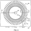
- a current sense coil 460 is disposed on a printed circuit board (“PCB") 400.
- the current sense coil 460 is substantially similar to the current sense coil 360 and only the differences therebetween are described below to avoid unnecessary repetition.
- the PCB 400 may be a multilayer PCB formed from any suitable dielectric material, including, but not limited to composite materials composed of woven fiberglass cloth with an epoxy resin binder such as FR-4 grade as designated by National Electrical Manufacturers Association.
- the PCB 400 defines an opening 402 therethrough for passage of the active lead 342.
- the current sense coil 460 includes an outer coil 470 and an inner conductor 472.
- the outer coil 470 is formed by a plurality of upper conductive traces 470a and lower conductive traces 470b interconnected by a plurality of inner conductive vias 470c and outer conductive vias 470d.
- the upper and lower conductive traces 470a and 470b may be printed on respective upper and lower surfaces 400a, 400b of the PCB 400.
- the inner conductor 472 is disposed in between the upper and lower conductive traces 470a and 470b and is embedded within the PCB 400 ( FIG. 6 ).
- a current sense coil 560 which is substantially similar to the current sense coil 360, includes two balancing portions 560a and 560b, which are symmetrical about an axis "X-X" ( FIG. 7 ).
- the current sense coil 560 is also configured to couple to the sense circuit 362 ( FIG. 4 ).
- the current sense coil 560 includes an outer coil 570 (e.g., toroid) that acts as an active conductor wrapped around an inner conductor 572.
- the current sense coil 560 defines an opening 574, through which the current lead 342 ( FIG. 4 ) is passed through.
- the outer coil 570 includes two balancing portions 570a and 570b, each of which is coupled to a conditioning circuit (e.g., conditioning circuit 362) by a lead 571a and 571b, respectively.
- the inner conductor 572 also includes two balancing portions 572a and 572b, both of which are coupled to the conditioning circuit 362 by a center-tapped lead 573.
- Balancing portion 570a of the outer coil 570 is coupled to the balancing portion 572a of the inner conductor 572 at a node 576 and the balancing portion 570b of the outer coil 570 is coupled to the balancing portion 572b of the inner conductor 572 at a node 578.
- the balancing portions 570a and 572a along with counterpart balancing portions 570b and 572b form the balancing portions 560a and 560b of the current sense coil 560.
- the current sense coil 560 acts as an inductively loaded, center-tapped dipole antenna with the balancing portions 560a and 560b acting as two poles.
- any near-field alternating current with a differential component in a plane "A-A" ( FIG. 8 ) defined by the current sense coil 560 induces a differential voltage (and therefore current) in the outer coil 570 as represented by electrical fields 580a and 580b.
- a current sense coil 660 which is configured to cancel out the induced electrical fields, includes a first outer coil 670, a second outer coil 690, and an inner conductor 672 disposed therebetween.
- the current sense coil 660 is also configured to couple to the sense circuit 362 ( FIG. 4 ). Similar to the current sense coil 560 of FIGS. 7 and 8 , the current sense coil 660 also includes two balancing portions 660a and 660b.
- the first outer coil 670 includes a first balancing portion 670a, and a second balancing portion 670b.
- the second outer coil 690 includes a first balancing portion 690a and a second balancing portion 690b.
- the inner conductor 672 includes a first balancing portion 672a and a second balancing portion 672b.
- the first and second balancing portions 672a and 672b are coupled to the conditioning circuit 362 ( FIG. 4 ) by a center-tapped lead 673.
- the first outer coil 670 and the second outer coil 690 have the same shape, namely, arcuate, and define a surface area sufficient to insure that they are affected by external electric fields in the same manner and thus pick up the same amount of interference.
- Each of the first and second outer coils 670 and 690 are configured to detect the first magnetic field generated by the current passing through the active lead 342.
- first balancing portion 670a of the first outer coil 670 and the second balancing portion 690b of the second outer coil 690 are coupled to a first lead 671a
- second balancing portion 670b of the first outer coil 670 and the first balancing portion 690a of the second outer coil 690 are coupled to a second lead 671b
- first balancing portions 670a and 690a of the first and second outer coils 670 and 690 respectively, are coupled to the first balancing portion 672a of the inner conductor 672 at a first node 674.
- the second balancing portions 670b and 690b of the first and second outer coils 670 and 690, respectively, are coupled to the second balancing portion 672b of the inner conductor 672 at a second node 676.
- the first and second balancing portions 690a and 690b of the second outer coil 690 are also wound in an opposite direction from that of the first and second balancing portions 670a and 670b of the first outer coil 670.
- first and second outer coils 670 and 690 namely, opposing pairs of the first balancing portions 670a and 690a and second balancing portions 690a and 690b being wound in opposite direction and coupled together at first and second leads 671a and 671b, respectively, cancels out induced electrical fields 680a and 680b since the voltage corresponding to each of the fields 680a and 680b is supplied to each of the leads 671a and 671b.
- a current sense coil 760 which is also configured to cancel out the induced electrical fields, includes an outer coil 770, a conductive plane 790, and an inner conductor 772 disposed therebetween.
- the current sense coil 760 is also configured to couple to the sense circuit 362 ( FIG. 4 ). Similar to the current sense coil 660 of FIG. 9 , the current sense coil 760 also includes two balancing portions 760a and 760b.
- the outer coil 770 includes a first balancing portion 770a, and a second balancing portion 770b.
- the conductive plane 790 includes a first balancing portion 790a and a second balancing portion 790b.
- the inner conductor 772 includes a first balancing portion 772a and a second balancing portion 772b.
- the first and second balancing portions 772a and 772b are coupled to the conditioning circuit 362 by a center-tapped lead 773.
- the conductive plane 790 has a hemispherical shape and defines a surface area which covers the circular shape and area defined by the outer coil 770, which is similar to the shape and surface area of the outer coil 560 of FIG. 7 . This ensures that the conductive plane 790 is affected by external electric fields in the same manner as the outer coil 770, and thus, picks up the same amount of interference to cancel out the induced electrical fields.
- the first balancing portion 770a of the first outer coil 770 and the second balancing portion 790b of the conductive plane 790 are coupled to a first lead 771a, whereas the second balancing portion 770b of the first outer coil 770 and the first balancing portion 790a of the conductive plane 790 are coupled to a second lead 771b.
- the first balancing portion 770a of the outer coil 770 is coupled to the first balancing portion 772a of the inner conductor 772 at a first node 774.
- the second balancing portion 770b of the outer coil 770 is coupled to the second balancing portion 772b of the inner conductor 772 at a second node 776.
- Each of the current sense coils 670 and 770 of FIGS. 9 and 10 are coupled to the conditioning circuit 362 ( FIG. 4 ), which processes the voltage signals passed thereto.
- the current sense coils 670 and 770 of FIGS. 9 and 10 may also be implemented within a multilayer PCB, namely, PCB 600 and PCB 700, respectively. With reference to FIGS.
- each of the components of the current sense coil 660 i.e., the first outer coil 670, the second outer coil 690, and the inner conductor 672 and counterpart components of the current sense coil 760 (i.e., the outer coil 770, the conductive plane 790, and the inner conductor 772) may be disposed across multiple layers of the PCB 600 and PCB 700, respectively, in a manner described above with respect to the current sense coil 460 and PCB 400.
- each of the components of the current sense coils 660 and/or 760 maybe formed by forming conductive traces on individual layers 600a, 600b, ... 600n of the PCB 600 and layers 700a, 700b, ... 700n of the PCB 700, respectively.
- the components of the current sense coils 660 and/or 760 may be interconnected across multiple layers by conductive vias, which pass through the dielectric layers of the PCB 600 and PCB 700.
Landscapes
- Engineering & Computer Science (AREA)
- Health & Medical Sciences (AREA)
- Physics & Mathematics (AREA)
- Power Engineering (AREA)
- Life Sciences & Earth Sciences (AREA)
- Surgery (AREA)
- General Physics & Mathematics (AREA)
- Biomedical Technology (AREA)
- Otolaryngology (AREA)
- Heart & Thoracic Surgery (AREA)
- Medical Informatics (AREA)
- Molecular Biology (AREA)
- Animal Behavior & Ethology (AREA)
- General Health & Medical Sciences (AREA)
- Public Health (AREA)
- Veterinary Medicine (AREA)
- Nuclear Medicine, Radiotherapy & Molecular Imaging (AREA)
- Plasma & Fusion (AREA)
- Surgical Instruments (AREA)
Abstract
Description
- The present disclosure relates to a current sensor for use with an electrosurgical generator configured to generate a radio frequency ("RF") waveform. In particular, the present disclosure relates to a current sense coil configured to eliminate and/or minimize effects of external voltage coupling.
- Electrosurgery involves application of high radio frequency electrical current to a surgical site to cut, ablate, desiccate, or coagulate tissue. In monopolar electrosurgery, a source or active electrode delivers RF alternating current from the electrosurgical generator to the targeted tissue. A patient return electrode is placed remotely from the active electrode to conduct the current back to the generator.
- In bipolar electrosurgery, return and active electrodes are placed in close proximity to each other such that an electrical circuit is formed between the two electrodes (e.g., in the case of an electrosurgical forceps). In this manner, the applied electrical current is limited to the body tissue positioned between the electrodes. Accordingly, bipolar electrosurgery generally involves the use of instruments where it is desired to achieve a focused delivery of electrosurgical energy between two electrodes.
- Conventional RF generators utilize a variety of sensors to measure properties of the generated RF waveforms. However, some of the sensors are more susceptible to external voltage coupling, which affects the accuracy and reliability of the measured signals. In particular, current sensors which utilize a sense coil are particularly susceptible to secondary or tertiary order current or voltage sources that are orthogonal to the flow of current being measured. This susceptibility introduces noise into the measured signals, thereby reducing inherent measurement accuracy of the sense coil. Accordingly, this makes measurements of very small currents, such as those generated by RF generators, inaccurate and unreliable. Although there have been attempts to design current sense coils by balancing and/or cancelling external electrical fields and other sources of interference, there is a need for an RF current sense coil configured to reduce and/or eliminate external voltage coupling.
- According to one embodiment of the present disclosure, a current sensor is disclosed. The current sensor includes a current sense coil disposed about a conductive lead, the current sense coil configured to sense a current passing through the conductive lead. The current sense coil includes: a first outer coil configured to detect a first magnetic field generated by the current; a second outer coil configured to detect the first magnetic field, the second outer coil further configured to cancel an electrical field induced in the first outer coil; and an inner conductor disposed between the first outer coil and the second outer coil, the inner conductor configured to detect a second magnetic field generated by the current.
- According to another embodiment of the present disclosure, an electrosurgical generator is disclosed. The electrosurgical generator includes: a power supply configured to output a direct current; a power converter coupled to the power supply, the power converter configured to generate a radio frequency current based on the direct current; at least one lead coupling the power converter to a terminal configured to couple to an electrosurgical instrument; and a current sensor. The current sensor includes: a current sense coil disposed about the at least one lead, the current sense coil configured to sense the radio frequency current passing through the at least one lead. The current sense coil includes: a first outer coil configured to detect a first magnetic field generated by the radio frequency current; a second outer coil configured to detect the first magnetic field, the second outer coil further configured to cancel an electrical field induced in the first outer coil; and an inner conductor disposed between the first outer coil and the second outer coil, the inner conductor configured to detect a second magnetic field generated by the radio frequency current.
- According to one aspect of any of the above embodiments, each of the first outer coil and the second outer coil includes a first balancing portion and a second balancing potion.
- According to one aspect of any of the above embodiments, the first balancing portion of the first outer coil and the second balancing portion of the second outer coil are coupled to a first lead.
- According to one aspect of any of the above embodiments, the second balancing portion of the first outer coil and the first balancing portion of the second outer coil are coupled to a second lead.
- According to one aspect of any of the above embodiments, the current sensor further includes a conditioning circuit coupled to the first lead and the second lead.
- According to one aspect of any of the above embodiments, each of the first outer coil and the second outer coil are coupled to the inner conductor.
- According to one aspect of any of the above embodiments, the current sensor further includes a printed circuit board having a plurality of dielectric layers.
- According to one aspect of any of the above embodiments, each of the first outer coil, the second outer coil, and the inner conductor are disposed on a corresponding dielectric layer of the plurality of dielectric layers.
- The present disclosure may be understood by reference to the accompanying drawings, when considered in conjunction with the subsequent detailed description, in which:
-
FIG. 1 is a perspective view of an electrosurgical system according to an embodiment of the present disclosure; -
FIG. 2 is a front view of an electrosurgical generator of the electrosurgical system ofFIG. 1 ; -
FIG. 3 is a schematic diagram of the electrosurgical generator ofFIG. 2 ; -
FIG. 4 is a schematic diagram of a current sensor of the electrosurgical generator ofFIG. 2 ; -
FIG. 5 is a schematic diagram of a current sense coil of the current sensor ofFIG. 4 disposed on a printed circuit board; -
FIG. 6 is a cross-sectional side view taken along a sectional line 6-6 of the current sense coil ofFIG. 5 ; -
FIG. 7 is a top schematic view of a current sense coil according to another embodiment of the present disclosure; -
FIG. 8 is a side schematic view of the current sense coil ofFIG. 7 ; -
FIG. 9 is a side schematic view of a current sense coil according to a further embodiment of the present disclosure; and -
FIG. 10 is a side schematic view of a current sense coil according to yet another embodiment of the present disclosure. - Particular embodiments of the present disclosure will be described below with reference to the accompanying drawings. In the following description, well-known functions or constructions are not described in detail to avoid obscuring the present disclosure in unnecessary detail. Those skilled in the art will understand that embodiments of the present disclosure may be adapted for use with any electrosurgical system, generator, and/or instrument. It should also be appreciated that different electrical and mechanical connections and other considerations may apply to each particular type of instrument.
- Briefly, an electrosurgical generator according to the present disclosure may be used in monopolar and/or bipolar electrosurgical procedures, including, for example, cutting, coagulation, ablation, and vessel sealing procedures. The generator may include a plurality of outputs for interfacing with various electrosurgical instruments (e.g., monopolar instruments, return electrode pads, bipolar electrosurgical forceps, footswitches, etc.). Further, the generator may include electronic circuitry configured to generate radio frequency energy specifically suited for powering electrosurgical devices operating in various electrosurgical modes (e.g., cut, blend, coagulate, division with hemostasis, fulgurate, spray, etc.) and procedures (e.g., monopolar, bipolar, vessel sealing).
- Referring to
FIG. 1 , anelectrosurgical system 10 according to the present disclosure includes one or more monopolarelectrosurgical instruments 20 having one or more active electrodes 23 (e.g., electrosurgical cutting probe, ablation electrode(s), etc.) for treating tissue of a patient. Electrosurgical alternating RF current is supplied to theinstrument 20 by agenerator 200 via asupply line 24 that is connected to an active terminal 350 (FIG. 3 ) of thegenerator 200, allowing theinstrument 20 to cut, coagulate, and/or otherwise treat tissue. The RF current is returned to thegenerator 200 through areturn electrode pad 26 via areturn line 28 at a return terminal 352 (FIG. 3 ) of thegenerator 200. For monopolar operation, thesystem 10 may include a plurality ofreturn electrode pads 26 that, in use, are disposed on a patient to minimize the chances of tissue damage by maximizing the overall contact area with the patient. In addition, thegenerator 200 and thereturn electrode pads 26 may be configured for monitoring tissue-to-patient contact to ensure that sufficient contact exists therebetween. - The
system 10 may also include one or more bipolar electrosurgical instruments, for example, a bipolarelectrosurgical forceps 30 having one or more electrodes for treating tissue of a patient. Theelectrosurgical forceps 30 includes ahousing 31 and opposingjaw members shaft 32. Thejaw members active electrodes 34 and areturn electrode 36 disposed therein, respectively. Theactive electrode 34 and thereturn electrode 36 are connected to thegenerator 200 throughcable 38 that includes the supply andreturn lines return terminals FIG. 3 ). Theelectrosurgical forceps 30 is coupled to thegenerator 200 at a port having connections to the active andreturn terminals 350 and 352 (e.g., pins) via a plug disposed at the end of thecable 38, wherein the plug includes contacts from the supply andreturn lines - With reference to
FIG. 2 , afront face 240 of thegenerator 200 is shown. Thegenerator 200 may include a plurality of ports 250-262 to accommodate various types of electrosurgical instruments (e.g., monopolarelectrosurgical instrument 20,electrosurgical forceps 30, etc.). - The
generator 200 includes auser interface 241 having one ormore display screens screens generator 200 includes suitable input controls (e.g., buttons, activators, switches, touch screen, etc.) for controlling thegenerator 200. Thescreens electrosurgical forceps 30, etc.). The user may adjust inputs by simply touching corresponding menu options. -
Screen 242 controls monopolar output and the devices connected to theports Port 250 is configured to couple to a monopolar electrosurgical instrument (e.g., electrosurgical instrument 20) andport 252 is configured to couple to a foot switch (not shown). The foot switch provides for additional inputs (e.g., replicating inputs of the generator 200). Theport 254 is configured to couple to thereturn electrode pad 26. Screen 244 controls monopolar and bipolar output and the devices connected to theports Port 256 is configured to couple to other monopolar instruments.Port 258 is configured to couple to a bipolar instrument (not shown). -
Screen 246 controls theelectrosurgical forceps 30 that may be plugged into one of theports generator 200 outputs energy through theports electrosurgical forceps 30. In particular,screen 246 outputs a user interface that allows the user to input a user-defined intensity setting for each of theports FIG. 3 ) where the setting may be saved in memory. In embodiments, the intensity setting may be a number scale, such as for example, from one to ten or one to five. In embodiments, the intensity setting may be associated with an output curve of thegenerator 200. The intensity settings may be specific for eachelectrosurgical forceps 30 being utilized, such that various instruments provide the user with a specific intensity scale corresponding to theelectrosurgical forceps 30. The active and returnterminals - With reference to
FIG. 3 , thegenerator 200 also includes acontroller 324, apower supply 326, and apower converter 332. Thepower supply 326 may be a high voltage, DC power supply connected to an AC source (e.g., line voltage) and provides high voltage, DC power to thepower converter 332, which then converts high voltage, DC power into RF energy and delivers the energy to theactive terminal 350. The energy is returned thereto via thereturn terminal 352. In particular, electrosurgical energy for energizing the monopolarelectrosurgical instrument 20 and/orelectrosurgical forceps 30 is delivered through the active and returnterminals terminals power converter 332 through anisolation transformer 340. More specifically, theisolation transformer 340 includes a primary winding 340a coupled to thepower converter 332 and a secondary winding 340b having anactive lead 342 coupled to theactive terminal 350 and areturn lead 344 coupled to thereturn lead 344. The output ofpower converter 332 transmits current through theisolation transformer 340 to the load "Z", e.g., tissue being treated. - The
power converter 332 is configured to operate in a plurality of modes, during which thegenerator 200 outputs corresponding waveforms having specific duty cycles, peak voltages, crest factors, etc. It is envisioned that in other embodiments, thegenerator 200 may be based on other types of suitable power supplytopologies. Power converter 332 may be a resonant RF amplifier or a non-resonant RF amplifier. A non-resonant RF amplifier, as used herein, denotes an amplifier lacking any tuning components, e.g., conductors, capacitors, etc., disposed between the power converter and the load "Z." - The
controller 324 includes a processor (not shown) operably connected to a memory (not shown), which may include one or more of volatile, non-volatile, magnetic, optical, or electrical media, such as read-only memory (ROM), random access memory (RAM), electrically-erasable programmable ROM (EEPROM), non-volatile RAM (NVRAM), or flash memory. The processor may be any suitable processor (e.g., control circuit) adapted to perform the operations, calculations, and/or set of instructions described in the present disclosure including, but not limited to, a hardware processor, a field programmable gate array (FPGA), a digital signal processor (DSP), a central processing unit (CPU), a microprocessor, and combinations thereof. Those skilled in the art will appreciate that the processor may be substituted for by using any logic processor (e.g., control circuit) adapted to perform the calculations and/or set of instructions described herein. - The
controller 324 includes output ports that are operably connected to thepower supply 326 and/or thepower converter 332 allowing thecontroller 324 to control the output of thegenerator 200 according to either open and/or closed control loop schemes. A closed loop control scheme is a feedback control loop, in which a plurality of sensors measure a variety of tissue and energy properties (e.g., tissue impedance, tissue temperature, output power, current and/or voltage, etc.), and provide feedback to thecontroller 324. Thecontroller 324 then controls thepower supply 326 and/or thepower converter 332, which adjusts power delivered to and/or from thepower converter 332, respectively. Thecontroller 324 also receives input signals from the input controls of thegenerator 200, theinstrument 20, and/orelectrosurgical forceps 30. Thecontroller 324 utilizes the input signals to adjust power outputted by thegenerator 200 and/or performs other control functions thereon. - The
controller 324 may perform various mathematical computations in order to control thepower supply 326 and/or thepower converter 332 to generate an RF waveform having a desired shape and energy content. Examples of computations performed by thecontroller 324 include, but are not limited to, calculating instantaneous and/or root mean square power levels, amount of energy delivered on a cycle by cycle basis, load impedance, etc. - The
generator 200 according to the present disclosure may also include a plurality of sensors, namely, avoltage sensor 336 and acurrent sensor 338. Thevoltage sensor 336 is coupled to the active and return leads 342, 344 and measure RF voltage supplied to the active and returnterminals current sensor 338 is coupled to the active and/or return leads 342, 344 and measures RF current supplied to the active and returnterminals generator 200 may also include additional sensors (not shown) coupled to thepower supply 326. - With reference to
FIG. 4 , thecurrent sensor 338 includes acurrent sense coil 360 and aconditioning circuit 362. Theconditioning circuit 362 processes (e.g., integrates) the signal from thecurrent sense coil 360, which is a time-derivative of the current being measured passing through theactive lead 342. Thecurrent sense coil 360 includes an outer coil 370 (e.g., a toroid) that acts as an active conductor wrapped around an inner conductor 372 (e.g., a "Bucking coil") that acts as a return conductor. Thecurrent sense coil 360 defines anopening 374, through which thecurrent lead 342 is passed through. This configuration allows for theouter coil 370 and theinner conductor 372 to measure current passing through theactive lead 342 based on the magnetic fields generated by the current. In particular, theouter coil 370 detects a first magnetic field generated by the current passing through theactive lead 342 and produces a first voltage corresponding thereto. Theouter coil 370 may also detect a second magnetic field, which produces a second voltage. The second magnetic field is orthogonal to the first magnetic field and is not related to the sensed current, and thus, its effects on theouter coil 370 is removed to achieve accurate current measurement. Theinner conductor 372 senses the second magnetic field and produces a third voltage proportional to the second magnetic field. The second voltage and third voltage have approximately the same magnitude such that they cancel each other, which allows for theconditioning circuit 362 to determine the first voltage corresponding to the current passing through theactive lead 342. In embodiments, thecurrent sense coil 360 may be implemented on a printed circuit board. In further embodiments, thecurrent sense coil 360 may also be implemented by winding a wire around acore 343, which may be a toroidal magnetic core or a low permeability core. - With reference to
FIGS. 5 and6 , acurrent sense coil 460 is disposed on a printed circuit board ("PCB") 400. Thecurrent sense coil 460 is substantially similar to thecurrent sense coil 360 and only the differences therebetween are described below to avoid unnecessary repetition. ThePCB 400 may be a multilayer PCB formed from any suitable dielectric material, including, but not limited to composite materials composed of woven fiberglass cloth with an epoxy resin binder such as FR-4 grade as designated by National Electrical Manufacturers Association. ThePCB 400 defines anopening 402 therethrough for passage of theactive lead 342. Thecurrent sense coil 460 includes anouter coil 470 and aninner conductor 472. Theouter coil 470 is formed by a plurality of upperconductive traces 470a and lowerconductive traces 470b interconnected by a plurality of innerconductive vias 470c and outerconductive vias 470d. The upper and lowerconductive traces lower surfaces PCB 400. Theinner conductor 472 is disposed in between the upper and lowerconductive traces FIG. 6 ). - With reference to
FIGS. 7 and 8 , acurrent sense coil 560, which is substantially similar to thecurrent sense coil 360, includes two balancingportions FIG. 7 ). Thecurrent sense coil 560 is also configured to couple to the sense circuit 362 (FIG. 4 ). Thecurrent sense coil 560 includes an outer coil 570 (e.g., toroid) that acts as an active conductor wrapped around aninner conductor 572. Thecurrent sense coil 560 defines anopening 574, through which the current lead 342 (FIG. 4 ) is passed through. Theouter coil 570 includes two balancingportions inner conductor 572 also includes two balancingportions conditioning circuit 362 by a center-tappedlead 573. Balancingportion 570a of theouter coil 570 is coupled to the balancingportion 572a of theinner conductor 572 at anode 576 and the balancingportion 570b of theouter coil 570 is coupled to the balancingportion 572b of theinner conductor 572 at anode 578. Thus, the balancingportions counterpart balancing portions balancing portions current sense coil 560. - Although, this configuration illustrated in
FIGS. 7 and 8 provides for cancellation of some unwanted external electric fields, it may result in other interference. In particular, thecurrent sense coil 560 acts as an inductively loaded, center-tapped dipole antenna with the balancingportions FIG. 8 ) defined by thecurrent sense coil 560, induces a differential voltage (and therefore current) in theouter coil 570 as represented byelectrical fields - With reference to
FIG. 9 , acurrent sense coil 660, which is configured to cancel out the induced electrical fields, includes a firstouter coil 670, a secondouter coil 690, and aninner conductor 672 disposed therebetween. Thecurrent sense coil 660 is also configured to couple to the sense circuit 362 (FIG. 4 ). Similar to thecurrent sense coil 560 ofFIGS. 7 and 8 , thecurrent sense coil 660 also includes two balancingportions outer coil 670 includes afirst balancing portion 670a, and asecond balancing portion 670b. The secondouter coil 690 includes afirst balancing portion 690a and asecond balancing portion 690b. Theinner conductor 672 includes afirst balancing portion 672a and asecond balancing portion 672b. The first andsecond balancing portions FIG. 4 ) by a center-tappedlead 673. - The first
outer coil 670 and the secondouter coil 690 have the same shape, namely, arcuate, and define a surface area sufficient to insure that they are affected by external electric fields in the same manner and thus pick up the same amount of interference. Each of the first and secondouter coils active lead 342. - With continued reference to
FIG. 9 , thefirst balancing portion 670a of the firstouter coil 670 and thesecond balancing portion 690b of the secondouter coil 690 are coupled to afirst lead 671a, whereas thesecond balancing portion 670b of the firstouter coil 670 and thefirst balancing portion 690a of the secondouter coil 690 are coupled to asecond lead 671b. In addition, thefirst balancing portions outer coils first balancing portion 672a of theinner conductor 672 at afirst node 674. Thesecond balancing portions outer coils second balancing portion 672b of theinner conductor 672 at asecond node 676. The first andsecond balancing portions outer coil 690 are also wound in an opposite direction from that of the first andsecond balancing portions outer coil 670. The inverse configuration of the first and secondouter coils first balancing portions second balancing portions second leads electrical fields fields leads - With reference to
FIG. 10 acurrent sense coil 760, which is also configured to cancel out the induced electrical fields, includes anouter coil 770, aconductive plane 790, and aninner conductor 772 disposed therebetween. Thecurrent sense coil 760 is also configured to couple to the sense circuit 362 (FIG. 4 ). Similar to thecurrent sense coil 660 ofFIG. 9 , thecurrent sense coil 760 also includes two balancingportions outer coil 770 includes afirst balancing portion 770a, and asecond balancing portion 770b. Theconductive plane 790 includes afirst balancing portion 790a and asecond balancing portion 790b. Theinner conductor 772 includes afirst balancing portion 772a and asecond balancing portion 772b. The first andsecond balancing portions conditioning circuit 362 by a center-tappedlead 773. - The
conductive plane 790 has a hemispherical shape and defines a surface area which covers the circular shape and area defined by theouter coil 770, which is similar to the shape and surface area of theouter coil 560 ofFIG. 7 . This ensures that theconductive plane 790 is affected by external electric fields in the same manner as theouter coil 770, and thus, picks up the same amount of interference to cancel out the induced electrical fields. Thefirst balancing portion 770a of the firstouter coil 770 and thesecond balancing portion 790b of theconductive plane 790 are coupled to afirst lead 771a, whereas thesecond balancing portion 770b of the firstouter coil 770 and thefirst balancing portion 790a of theconductive plane 790 are coupled to asecond lead 771b. In addition, thefirst balancing portion 770a of theouter coil 770 is coupled to thefirst balancing portion 772a of theinner conductor 772 at afirst node 774. Thesecond balancing portion 770b of theouter coil 770 is coupled to thesecond balancing portion 772b of theinner conductor 772 at asecond node 776. The inverse connection of theouter coil 770 and theconductive plane 790, namely, opposing pairs of thefirst balancing portions second balancing portions second leads electrical fields fields leads - Each of the current sense coils 670 and 770 of
FIGS. 9 and10 , respectively, are coupled to the conditioning circuit 362 (FIG. 4 ), which processes the voltage signals passed thereto. The current sense coils 670 and 770 ofFIGS. 9 and10 may also be implemented within a multilayer PCB, namely,PCB 600 andPCB 700, respectively. With reference toFIGS. 9 and10 , each of the components of the current sense coil 660 (i.e., the firstouter coil 670, the secondouter coil 690, and the inner conductor 672) and counterpart components of the current sense coil 760 (i.e., theouter coil 770, theconductive plane 790, and the inner conductor 772) may be disposed across multiple layers of thePCB 600 andPCB 700, respectively, in a manner described above with respect to thecurrent sense coil 460 andPCB 400. In particular, each of the components of the current sense coils 660 and/or 760 maybe formed by forming conductive traces onindividual layers PCB 600 andlayers PCB 700, respectively. In addition, the components of the current sense coils 660 and/or 760 may be interconnected across multiple layers by conductive vias, which pass through the dielectric layers of thePCB 600 andPCB 700. - While several embodiments of the disclosure have been shown in the drawings and/or described herein, it is not intended that the disclosure be limited thereto, as it is intended that the disclosure be as broad in scope as the art will allow and that the specification be read likewise. Therefore, the above description should not be construed as limiting, but merely as exemplifications of particular embodiments. Those skilled in the art will envision other modifications within the scope of the claims appended hereto.
- The invention may be described by reference to the following numbered paragraphs:-
- 1. A current sensor comprising:
- a current sense coil disposed about a conductive lead, the current sense coil configured to sense a current passing through the conductive lead, the current sense coil including:
- a first outer coil configured to detect a first magnetic field generated by the current;
- a second outer coil configured to detect the first magnetic field, the second outer coil further configured to cancel an electrical field induced in the first outer coil; and
- an inner conductor disposed between the first outer coil and the second outer coil, the inner conductor configured to detect a second magnetic field generated by the current.
- a current sense coil disposed about a conductive lead, the current sense coil configured to sense a current passing through the conductive lead, the current sense coil including:
- 2. The current sensor according to
paragraph 1, wherein each of the first outer coil and the second outer coil includes a first balancing portion and a second balancing portion. - 3. The current sensor according to
paragraph 2, wherein the first balancing portion of the first outer coil and the second balancing portion of the second outer coil are coupled to a first lead. - 4. The current sensor according to paragraph 3, wherein the second balancing portion of the first outer coil and the first balancing portion of the second outer coil is coupled to a second lead.
- 5. The current sensor according to paragraph 4, further comprising a conditioning circuit coupled to the first lead and the second lead.
- 6. The current sensor according to
paragraph 1, wherein each of the first outer coil and the second outer coil are coupled to the inner conductor. - 7. The current sensor according to
paragraph 1, further comprising a printed circuit board having a plurality of dielectric layers. - 8. The current sensor according to paragraph 7, wherein each of the first outer coil, the second outer coil, and the inner conductor is disposed on a corresponding dielectric layer of the plurality of dielectric layers.
- 9. An electrosurgical generator comprising:
- a power supply configured to output a direct current;
- a power converter coupled to the power supply, the power converter configured to generate a radio frequency current based on the direct current;
- at least one lead coupling the power converter to a terminal configured to couple to an electrosurgical instrument; and
- a current sensor including:
- a current sense coil disposed about the at least one lead, the current sense coil configured to sense the radio frequency current passing through the at least one lead, the current sense coil including:
- a first outer coil configured to detect a first magnetic field generated by the radio frequency current;
a second outer coil configured to detect the first magnetic field, the second outer coil further configured to cancel an electrical field induced in the first outer coil; and - an inner conductor disposed between the first outer coil and the second outer coil, the inner conductor configured to detect a second magnetic field generated by the radio frequency current.
- a first outer coil configured to detect a first magnetic field generated by the radio frequency current;
- a current sense coil disposed about the at least one lead, the current sense coil configured to sense the radio frequency current passing through the at least one lead, the current sense coil including:
- 10. The electrosurgical generator according to paragraph 9, wherein each of the first outer coil and the second outer coil includes a first balancing portion and a second balancing potion.
- 11. The electrosurgical generator according to
paragraph 10, wherein the first balancing portion of the first outer coil and the second balancing portion of the second outer coil are coupled to a first lead. - 12. The electrosurgical generator according to paragraph 11, wherein the second balancing portion of the first outer coil and the first balancing portion of the second outer coil are coupled to a second lead.
- 13. The electrosurgical generator according to paragraph 12, wherein the current sensor further includes a conditioning circuit coupled to the first lead and the second lead.
- 14. The electrosurgical generator according to paragraph 9, wherein each of the first outer coil and the second outer coil is coupled to the inner conductor.
- 15. The electrosurgical generator according to paragraph 9, wherein the current sensor further includes a printed circuit board having a plurality of dielectric layers.
- 16. The electrosurgical generator according to paragraph 15, wherein each of the first outer coil, the second outer coil, and the inner conductor is disposed on a corresponding dielectric layer of the plurality of dielectric layers.
Claims (15)
- A current sensor comprising:a current sense coil disposed about a conductive lead, the current sense coil configured to sense a current passing through the conductive lead, the current sense coil including:a first outer coil configured to detect a first magnetic field generated by the current;a second outer coil configured to detect the first magnetic field, the second outer coil further configured to cancel an electrical field induced in the first outer coil; andan inner conductor disposed between the first outer coil and the second outer coil, the inner conductor configured to detect a second magnetic field generated by the current.
- The current sensor according to claim 1, wherein each of the first outer coil and the second outer coil includes a first balancing portion and a second balancing portion.
- The current sensor according to claim 2, wherein the first balancing portion of the first outer coil and the second balancing portion of the second outer coil are coupled to a first lead.
- The current sensor according to claim 3, wherein the second balancing portion of the first outer coil and the first balancing portion of the second outer coil is coupled to a second lead.
- The current sensor according to claim 4, further comprising a conditioning circuit coupled to the first lead and the second lead.
- The current sensor according to any preceding claim, wherein each of the first outer coil and the second outer coil are coupled to the inner conductor.
- The current sensor according to any preceding claim, further comprising a printed circuit board having a plurality of dielectric layers, preferably wherein each of the first outer coil, the second outer coil, and the inner conductor is disposed on a corresponding dielectric layer of the plurality of dielectric layers.
- An electrosurgical generator comprising:a power supply configured to output a direct current;a power converter coupled to the power supply, the power converter configured to generate a radio frequency current based on the direct current;at least one lead coupling the power converter to a terminal configured to couple to an electrosurgical instrument; anda current sensor including:a current sense coil disposed about the at least one lead, the current sense coil configured to sense the radio frequency current passing through the at least one lead, the current sense coil including:a first outer coil configured to detect a first magnetic field generated by the radio frequency current;
a second outer coil configured to detect the first magnetic field, the second outer coil further configured to cancel an electrical field induced in the first outer coil; andan inner conductor disposed between the first outer coil and the second outer coil, the inner conductor configured to detect a second magnetic field generated by the radio frequency current. - The electrosurgical generator according to claim 8, wherein each of the first outer coil and the second outer coil includes a first balancing portion and a second balancing potion.
- The electrosurgical generator according to claim 9, wherein the first balancing portion of the first outer coil and the second balancing portion of the second outer coil are coupled to a first lead.
- The electrosurgical generator according to claim 10, wherein the second balancing portion of the first outer coil and the first balancing portion of the second outer coil are coupled to a second lead.
- The electrosurgical generator according to claim 11, wherein the current sensor further includes a conditioning circuit coupled to the first lead and the second lead.
- The electrosurgical generator according to any preceding claim, wherein each of the first outer coil and the second outer coil is coupled to the inner conductor.
- The electrosurgical generator according to any preceding claim, wherein the current sensor further includes a printed circuit board having a plurality of dielectric layers.
- The electrosurgical generator according to claim 14, wherein each of the first outer coil, the second outer coil, and the inner conductor is disposed on a corresponding dielectric layer of the plurality of dielectric layers.
Applications Claiming Priority (1)
| Application Number | Priority Date | Filing Date | Title |
|---|---|---|---|
| US15/144,341 US10908187B2 (en) | 2016-05-02 | 2016-05-02 | Current sensor with reduced voltage coupling |
Publications (2)
| Publication Number | Publication Date |
|---|---|
| EP3241513A1 true EP3241513A1 (en) | 2017-11-08 |
| EP3241513B1 EP3241513B1 (en) | 2020-04-01 |
Family
ID=58668759
Family Applications (1)
| Application Number | Title | Priority Date | Filing Date |
|---|---|---|---|
| EP17168928.4A Active EP3241513B1 (en) | 2016-05-02 | 2017-05-02 | Current sensor with reduced voltage coupling |
Country Status (2)
| Country | Link |
|---|---|
| US (2) | US10908187B2 (en) |
| EP (1) | EP3241513B1 (en) |
Cited By (2)
| Publication number | Priority date | Publication date | Assignee | Title |
|---|---|---|---|---|
| CN108362925A (en) * | 2018-02-22 | 2018-08-03 | 西安交通大学 | The Zero flux checking of great current system and method for double figure of eight three wires magnetic field cancellations |
| WO2020015949A1 (en) * | 2018-07-20 | 2020-01-23 | Siemens Aktiengesellschaft | Arrangement having a spiralled conductor strand, and method for producing such an arrangement |
Families Citing this family (5)
| Publication number | Priority date | Publication date | Assignee | Title |
|---|---|---|---|---|
| US10969409B2 (en) * | 2018-12-28 | 2021-04-06 | General Electric Company | Miniaturized current sensors |
| DE102019102567B3 (en) * | 2019-02-01 | 2020-03-05 | Dr. Ing. H.C. F. Porsche Aktiengesellschaft | Sensor device for measuring direct and alternating currents |
| EP4473642A1 (en) | 2022-02-03 | 2024-12-11 | WiTricity Corporation | Foreign object detection using hybrid inductive and capacitive sensing |
| KR20240146029A (en) * | 2022-02-03 | 2024-10-07 | 위트리시티 코포레이션 | Foreign body detection using combined inductive and thermal sensing |
| EP4706569A1 (en) * | 2024-09-05 | 2026-03-11 | Erbe Elektromedizin GmbH | Electrosurgical apparatus with current sensor for treatment current |
Citations (2)
| Publication number | Priority date | Publication date | Assignee | Title |
|---|---|---|---|---|
| EP2742887A1 (en) * | 2012-12-17 | 2014-06-18 | Covidien LP | System and method for voltage and current sensing |
| US20140167733A1 (en) * | 2012-12-17 | 2014-06-19 | Covidien Lp | System and method for voltage and current sensing |
Family Cites Families (43)
| Publication number | Priority date | Publication date | Assignee | Title |
|---|---|---|---|---|
| US3252052A (en) | 1963-08-23 | 1966-05-17 | Jacuzzi Bros Inc | Leakage detection and control circuit |
| US3601126A (en) | 1969-01-08 | 1971-08-24 | Electro Medical Systems Inc | High frequency electrosurgical apparatus |
| US3683923A (en) | 1970-09-25 | 1972-08-15 | Valleylab Inc | Electrosurgery safety circuit |
| US3697808A (en) | 1970-11-23 | 1972-10-10 | Safety Co The | System for monitoring chassis potential and ground continuity |
| US3885569A (en) | 1972-11-21 | 1975-05-27 | Birtcher Corp | Electrosurgical unit |
| US3913583A (en) | 1974-06-03 | 1975-10-21 | Sybron Corp | Control circuit for electrosurgical units |
| JPS5275882A (en) | 1975-12-20 | 1977-06-25 | Olympus Optical Co | High frequency electric knife |
| US4437464A (en) | 1981-11-09 | 1984-03-20 | C.R. Bard, Inc. | Electrosurgical generator safety apparatus |
| US4569345A (en) | 1984-02-29 | 1986-02-11 | Aspen Laboratories, Inc. | High output electrosurgical unit |
| DE3544443C2 (en) | 1985-12-16 | 1994-02-17 | Siemens Ag | HF surgery device |
| DE58906776D1 (en) | 1989-05-19 | 1994-03-03 | Siemens Ag | Circuit arrangement for controlling an electro-therapy device, in particular an HF surgical device. |
| US5540684A (en) | 1994-07-28 | 1996-07-30 | Hassler, Jr.; William L. | Method and apparatus for electrosurgically treating tissue |
| US5830212A (en) | 1996-10-21 | 1998-11-03 | Ndm, Inc. | Electrosurgical generator and electrode |
| US6566994B1 (en) * | 1997-03-17 | 2003-05-20 | Fluke Corporation | Coil for an AC current sensor |
| US5817091A (en) | 1997-05-20 | 1998-10-06 | Medical Scientific, Inc. | Electrosurgical device having a visible indicator |
| US6440157B1 (en) | 1998-07-10 | 2002-08-27 | Respiratory Support Products Inc. | Air warming system for providing a controlled temperature of air to an air blanket |
| EP1183543B1 (en) | 1999-05-25 | 2003-04-23 | Arbeitsgemeinschaft Prof. Hugel AGPH | Electrical current sensor |
| US20030181898A1 (en) | 1999-05-28 | 2003-09-25 | Bowers William J. | RF filter for an electrosurgical generator |
| US6313623B1 (en) | 2000-02-03 | 2001-11-06 | Mcgraw-Edison Company | High precision rogowski coil |
| US6511478B1 (en) | 2000-06-30 | 2003-01-28 | Scimed Life Systems, Inc. | Medical probe with reduced number of temperature sensor wires |
| DE20101454U1 (en) | 2001-01-27 | 2001-05-23 | Phoenix Contact Gmbh & Co., 32825 Blomberg | Circuit board-based current sensor |
| JP2003130894A (en) | 2001-10-29 | 2003-05-08 | Toshiba Corp | Current transformer |
| US6680608B2 (en) * | 2002-02-27 | 2004-01-20 | Mcgraw-Edison Company | Measuring current through an electrical conductor |
| JP2004119926A (en) | 2002-09-30 | 2004-04-15 | Toshiba Corp | Current transformer and current transformer system |
| US7041096B2 (en) | 2002-10-24 | 2006-05-09 | Synergetics Usa, Inc. | Electrosurgical generator apparatus |
| CA2432671C (en) | 2003-06-17 | 2008-11-04 | Kinectrics Inc. | Coreless current sensor |
| US7265533B2 (en) * | 2004-06-15 | 2007-09-04 | Power Measurement Ltd. | Non-intrusive power monitor |
| US20070063664A1 (en) | 2005-09-22 | 2007-03-22 | Avistar, Inc. | Phase identification apparatus having automatic gain control to prevent detector saturation |
| JP4674533B2 (en) * | 2005-12-02 | 2011-04-20 | パナソニック電工株式会社 | AC current detection coil |
| US7736359B2 (en) | 2006-01-12 | 2010-06-15 | Covidien Ag | RF return pad current detection system |
| US20080071260A1 (en) | 2006-09-15 | 2008-03-20 | Shores Ronald B | Electrosurgical generator and method using a high permeability, high resistivity transformer |
| US7579824B2 (en) | 2006-09-29 | 2009-08-25 | Gm Global Technology Operations, Inc. | High-precision Rogowski current transformer |
| CN101346047B (en) | 2007-07-13 | 2010-06-02 | 富葵精密组件(深圳)有限公司 | Manufacturing method of multilayer circuit board and inner substrate for manufacturing multilayer circuit board |
| US8152800B2 (en) | 2007-07-30 | 2012-04-10 | Vivant Medical, Inc. | Electrosurgical systems and printed circuit boards for use therewith |
| JP5069978B2 (en) * | 2007-08-31 | 2012-11-07 | 株式会社ダイヘン | Printed circuit board for current / voltage detection and current / voltage detector |
| US20090243590A1 (en) | 2008-04-01 | 2009-10-01 | Stephen James West | System and method for monitoring current in a conductor |
| US8398627B2 (en) | 2008-05-23 | 2013-03-19 | Gyrus Medical Limited | Electrosurgical generator and system |
| IT1391344B1 (en) | 2008-07-14 | 2011-12-05 | Lorenzo Peretto | ELECTRIC STABILIZABLE TRANSDUCER. |
| US8932282B2 (en) | 2009-08-03 | 2015-01-13 | Covidien Lp | Power level transitioning in a surgical instrument |
| US8636730B2 (en) | 2010-07-12 | 2014-01-28 | Covidien Lp | Polarity control of electrosurgical generator |
| US8968293B2 (en) | 2011-04-12 | 2015-03-03 | Covidien Lp | Systems and methods for calibrating power measurements in an electrosurgical generator |
| US9028482B2 (en) | 2011-07-19 | 2015-05-12 | Covidien Lp | Microwave and RF ablation system and related method for dynamic impedance matching |
| US8968297B2 (en) | 2011-07-19 | 2015-03-03 | Covidien Lp | Microwave and RF ablation system and related method for dynamic impedance matching |
-
2016
- 2016-05-02 US US15/144,341 patent/US10908187B2/en active Active
-
2017
- 2017-05-02 EP EP17168928.4A patent/EP3241513B1/en active Active
-
2021
- 2021-01-28 US US17/160,536 patent/US11703525B2/en active Active
Patent Citations (2)
| Publication number | Priority date | Publication date | Assignee | Title |
|---|---|---|---|---|
| EP2742887A1 (en) * | 2012-12-17 | 2014-06-18 | Covidien LP | System and method for voltage and current sensing |
| US20140167733A1 (en) * | 2012-12-17 | 2014-06-19 | Covidien Lp | System and method for voltage and current sensing |
Non-Patent Citations (2)
| Title |
|---|
| KOJOVIC L A ED - INSTITUTE OF ELECTRICAL AND ELECTRONICS ENGINEERS: "PCB Rogowski coil designs and performances for novel protective relaying", 2003 IEEE POWER ENGINEERING SOCIETY GENERAL MEETING. CONFERENCE PROCEEDINGS. TORONTO, ONTARIO, CANADA, JULY, 13 - 17, 2003; [IEEE POWER ENGINEERING SOCIETY], NEW YORK, NY : IEEE, US, vol. 2, 1 January 2003 (2003-01-01), pages 609 - 614, XP010685944, ISBN: 978-0-7803-7989-3, DOI: 10.1109/PES.2003.1270369 * |
| KOJOVIC L: "PCB Rogowski Coils Benefit Relay Protection", IEEE COMPUTER APPLICATIONS IN POWER, IEEE INC. NEW YORK, US, vol. 15, no. 3, 1 July 2002 (2002-07-01), pages 50 - 53, XP011092675, ISSN: 0895-0156, DOI: 10.1109/MCAP.2002.1018823 * |
Cited By (4)
| Publication number | Priority date | Publication date | Assignee | Title |
|---|---|---|---|---|
| CN108362925A (en) * | 2018-02-22 | 2018-08-03 | 西安交通大学 | The Zero flux checking of great current system and method for double figure of eight three wires magnetic field cancellations |
| CN108362925B (en) * | 2018-02-22 | 2020-03-17 | 西安交通大学 | Zero-flux large-current detection system and method for magnetic field cancellation of double-8-shaped three-wire |
| WO2020015949A1 (en) * | 2018-07-20 | 2020-01-23 | Siemens Aktiengesellschaft | Arrangement having a spiralled conductor strand, and method for producing such an arrangement |
| US11378596B2 (en) | 2018-07-20 | 2022-07-05 | Siemens Energy Global GmbH & Co. KG | Arrangement having a spiraled conductor strand, and method for producing such an arrangement |
Also Published As
| Publication number | Publication date |
|---|---|
| EP3241513B1 (en) | 2020-04-01 |
| US10908187B2 (en) | 2021-02-02 |
| US20210148953A1 (en) | 2021-05-20 |
| US11703525B2 (en) | 2023-07-18 |
| US20170315155A1 (en) | 2017-11-02 |
Similar Documents
| Publication | Publication Date | Title |
|---|---|---|
| EP3241513B1 (en) | Current sensor with reduced voltage coupling | |
| US9921243B2 (en) | System and method for voltage and current sensing | |
| US7794457B2 (en) | Transformer for RF voltage sensing | |
| EP2750618B1 (en) | System for dc tissue impedance sensing | |
| EP2742887B1 (en) | System for voltage and current sensing | |
| EP2620115B1 (en) | Electrosurgical apparatus with integrated energy sensing at tissue site | |
| EP2499983B1 (en) | Isolated current sensor | |
| US20200234872A1 (en) | Electrostatic shielding of planar magnetic devices of electrosurgical generators | |
| WO2025083577A1 (en) | Electrosurgical system and method for verifying accuracy of current sensor |
Legal Events
| Date | Code | Title | Description |
|---|---|---|---|
| PUAI | Public reference made under article 153(3) epc to a published international application that has entered the european phase |
Free format text: ORIGINAL CODE: 0009012 |
|
| STAA | Information on the status of an ep patent application or granted ep patent |
Free format text: STATUS: REQUEST FOR EXAMINATION WAS MADE |
|
| 17P | Request for examination filed |
Effective date: 20170502 |
|
| AK | Designated contracting states |
Kind code of ref document: A1 Designated state(s): AL AT BE BG CH CY CZ DE DK EE ES FI FR GB GR HR HU IE IS IT LI LT LU LV MC MK MT NL NO PL PT RO RS SE SI SK SM TR |
|
| AX | Request for extension of the european patent |
Extension state: BA ME |
|
| RBV | Designated contracting states (corrected) |
Designated state(s): AL AT BE BG CH CY CZ DE DK EE ES FI FR GB GR HR HU IE IS IT LI LT LU LV MC MK MT NL NO PL PT RO RS SE SI SK SM TR |
|
| STAA | Information on the status of an ep patent application or granted ep patent |
Free format text: STATUS: EXAMINATION IS IN PROGRESS |
|
| 17Q | First examination report despatched |
Effective date: 20190212 |
|
| GRAP | Despatch of communication of intention to grant a patent |
Free format text: ORIGINAL CODE: EPIDOSNIGR1 |
|
| STAA | Information on the status of an ep patent application or granted ep patent |
Free format text: STATUS: GRANT OF PATENT IS INTENDED |
|
| RIC1 | Information provided on ipc code assigned before grant |
Ipc: A61B 18/00 20060101ALN20191002BHEP Ipc: G01R 15/18 20060101ALI20191002BHEP Ipc: A61B 18/12 20060101AFI20191002BHEP |
|
| INTG | Intention to grant announced |
Effective date: 20191106 |
|
| RIN1 | Information on inventor provided before grant (corrected) |
Inventor name: SMITH, ROBERT B. |
|
| GRAS | Grant fee paid |
Free format text: ORIGINAL CODE: EPIDOSNIGR3 |
|
| GRAA | (expected) grant |
Free format text: ORIGINAL CODE: 0009210 |
|
| STAA | Information on the status of an ep patent application or granted ep patent |
Free format text: STATUS: THE PATENT HAS BEEN GRANTED |
|
| AK | Designated contracting states |
Kind code of ref document: B1 Designated state(s): AL AT BE BG CH CY CZ DE DK EE ES FI FR GB GR HR HU IE IS IT LI LT LU LV MC MK MT NL NO PL PT RO RS SE SI SK SM TR |
|
| REG | Reference to a national code |
Ref country code: GB Ref legal event code: FG4D |
|
| REG | Reference to a national code |
Ref country code: CH Ref legal event code: EP Ref country code: AT Ref legal event code: REF Ref document number: 1250348 Country of ref document: AT Kind code of ref document: T Effective date: 20200415 |
|
| REG | Reference to a national code |
Ref country code: DE Ref legal event code: R096 Ref document number: 602017013836 Country of ref document: DE |
|
| REG | Reference to a national code |
Ref country code: IE Ref legal event code: FG4D |
|
| PG25 | Lapsed in a contracting state [announced via postgrant information from national office to epo] |
Ref country code: BG Free format text: LAPSE BECAUSE OF FAILURE TO SUBMIT A TRANSLATION OF THE DESCRIPTION OR TO PAY THE FEE WITHIN THE PRESCRIBED TIME-LIMIT Effective date: 20200701 |
|
| REG | Reference to a national code |
Ref country code: NL Ref legal event code: MP Effective date: 20200401 |
|
| REG | Reference to a national code |
Ref country code: LT Ref legal event code: MG4D |
|
| PG25 | Lapsed in a contracting state [announced via postgrant information from national office to epo] |
Ref country code: CZ Free format text: LAPSE BECAUSE OF FAILURE TO SUBMIT A TRANSLATION OF THE DESCRIPTION OR TO PAY THE FEE WITHIN THE PRESCRIBED TIME-LIMIT Effective date: 20200401 Ref country code: IS Free format text: LAPSE BECAUSE OF FAILURE TO SUBMIT A TRANSLATION OF THE DESCRIPTION OR TO PAY THE FEE WITHIN THE PRESCRIBED TIME-LIMIT Effective date: 20200801 Ref country code: PT Free format text: LAPSE BECAUSE OF FAILURE TO SUBMIT A TRANSLATION OF THE DESCRIPTION OR TO PAY THE FEE WITHIN THE PRESCRIBED TIME-LIMIT Effective date: 20200817 Ref country code: LT Free format text: LAPSE BECAUSE OF FAILURE TO SUBMIT A TRANSLATION OF THE DESCRIPTION OR TO PAY THE FEE WITHIN THE PRESCRIBED TIME-LIMIT Effective date: 20200401 Ref country code: NO Free format text: LAPSE BECAUSE OF FAILURE TO SUBMIT A TRANSLATION OF THE DESCRIPTION OR TO PAY THE FEE WITHIN THE PRESCRIBED TIME-LIMIT Effective date: 20200701 Ref country code: FI Free format text: LAPSE BECAUSE OF FAILURE TO SUBMIT A TRANSLATION OF THE DESCRIPTION OR TO PAY THE FEE WITHIN THE PRESCRIBED TIME-LIMIT Effective date: 20200401 Ref country code: NL Free format text: LAPSE BECAUSE OF FAILURE TO SUBMIT A TRANSLATION OF THE DESCRIPTION OR TO PAY THE FEE WITHIN THE PRESCRIBED TIME-LIMIT Effective date: 20200401 Ref country code: SE Free format text: LAPSE BECAUSE OF FAILURE TO SUBMIT A TRANSLATION OF THE DESCRIPTION OR TO PAY THE FEE WITHIN THE PRESCRIBED TIME-LIMIT Effective date: 20200401 Ref country code: GR Free format text: LAPSE BECAUSE OF FAILURE TO SUBMIT A TRANSLATION OF THE DESCRIPTION OR TO PAY THE FEE WITHIN THE PRESCRIBED TIME-LIMIT Effective date: 20200702 |
|
| REG | Reference to a national code |
Ref country code: AT Ref legal event code: MK05 Ref document number: 1250348 Country of ref document: AT Kind code of ref document: T Effective date: 20200401 |
|
| PG25 | Lapsed in a contracting state [announced via postgrant information from national office to epo] |
Ref country code: RS Free format text: LAPSE BECAUSE OF FAILURE TO SUBMIT A TRANSLATION OF THE DESCRIPTION OR TO PAY THE FEE WITHIN THE PRESCRIBED TIME-LIMIT Effective date: 20200401 Ref country code: HR Free format text: LAPSE BECAUSE OF FAILURE TO SUBMIT A TRANSLATION OF THE DESCRIPTION OR TO PAY THE FEE WITHIN THE PRESCRIBED TIME-LIMIT Effective date: 20200401 Ref country code: LV Free format text: LAPSE BECAUSE OF FAILURE TO SUBMIT A TRANSLATION OF THE DESCRIPTION OR TO PAY THE FEE WITHIN THE PRESCRIBED TIME-LIMIT Effective date: 20200401 |
|
| PG25 | Lapsed in a contracting state [announced via postgrant information from national office to epo] |
Ref country code: AL Free format text: LAPSE BECAUSE OF FAILURE TO SUBMIT A TRANSLATION OF THE DESCRIPTION OR TO PAY THE FEE WITHIN THE PRESCRIBED TIME-LIMIT Effective date: 20200401 |
|
| REG | Reference to a national code |
Ref country code: DE Ref legal event code: R097 Ref document number: 602017013836 Country of ref document: DE |
|
| PG25 | Lapsed in a contracting state [announced via postgrant information from national office to epo] |
Ref country code: SM Free format text: LAPSE BECAUSE OF FAILURE TO SUBMIT A TRANSLATION OF THE DESCRIPTION OR TO PAY THE FEE WITHIN THE PRESCRIBED TIME-LIMIT Effective date: 20200401 Ref country code: RO Free format text: LAPSE BECAUSE OF FAILURE TO SUBMIT A TRANSLATION OF THE DESCRIPTION OR TO PAY THE FEE WITHIN THE PRESCRIBED TIME-LIMIT Effective date: 20200401 Ref country code: IT Free format text: LAPSE BECAUSE OF FAILURE TO SUBMIT A TRANSLATION OF THE DESCRIPTION OR TO PAY THE FEE WITHIN THE PRESCRIBED TIME-LIMIT Effective date: 20200401 Ref country code: DK Free format text: LAPSE BECAUSE OF FAILURE TO SUBMIT A TRANSLATION OF THE DESCRIPTION OR TO PAY THE FEE WITHIN THE PRESCRIBED TIME-LIMIT Effective date: 20200401 Ref country code: AT Free format text: LAPSE BECAUSE OF FAILURE TO SUBMIT A TRANSLATION OF THE DESCRIPTION OR TO PAY THE FEE WITHIN THE PRESCRIBED TIME-LIMIT Effective date: 20200401 Ref country code: EE Free format text: LAPSE BECAUSE OF FAILURE TO SUBMIT A TRANSLATION OF THE DESCRIPTION OR TO PAY THE FEE WITHIN THE PRESCRIBED TIME-LIMIT Effective date: 20200401 Ref country code: ES Free format text: LAPSE BECAUSE OF FAILURE TO SUBMIT A TRANSLATION OF THE DESCRIPTION OR TO PAY THE FEE WITHIN THE PRESCRIBED TIME-LIMIT Effective date: 20200401 Ref country code: CH Free format text: LAPSE BECAUSE OF NON-PAYMENT OF DUE FEES Effective date: 20200531 Ref country code: MC Free format text: LAPSE BECAUSE OF FAILURE TO SUBMIT A TRANSLATION OF THE DESCRIPTION OR TO PAY THE FEE WITHIN THE PRESCRIBED TIME-LIMIT Effective date: 20200401 Ref country code: LI Free format text: LAPSE BECAUSE OF NON-PAYMENT OF DUE FEES Effective date: 20200531 |
|
| PLBE | No opposition filed within time limit |
Free format text: ORIGINAL CODE: 0009261 |
|
| STAA | Information on the status of an ep patent application or granted ep patent |
Free format text: STATUS: NO OPPOSITION FILED WITHIN TIME LIMIT |
|
| PG25 | Lapsed in a contracting state [announced via postgrant information from national office to epo] |
Ref country code: PL Free format text: LAPSE BECAUSE OF FAILURE TO SUBMIT A TRANSLATION OF THE DESCRIPTION OR TO PAY THE FEE WITHIN THE PRESCRIBED TIME-LIMIT Effective date: 20200401 Ref country code: SK Free format text: LAPSE BECAUSE OF FAILURE TO SUBMIT A TRANSLATION OF THE DESCRIPTION OR TO PAY THE FEE WITHIN THE PRESCRIBED TIME-LIMIT Effective date: 20200401 |
|
| 26N | No opposition filed |
Effective date: 20210112 |
|
| REG | Reference to a national code |
Ref country code: BE Ref legal event code: MM Effective date: 20200531 |
|
| PG25 | Lapsed in a contracting state [announced via postgrant information from national office to epo] |
Ref country code: LU Free format text: LAPSE BECAUSE OF NON-PAYMENT OF DUE FEES Effective date: 20200502 |
|
| PG25 | Lapsed in a contracting state [announced via postgrant information from national office to epo] |
Ref country code: IE Free format text: LAPSE BECAUSE OF NON-PAYMENT OF DUE FEES Effective date: 20200502 |
|
| PG25 | Lapsed in a contracting state [announced via postgrant information from national office to epo] |
Ref country code: SI Free format text: LAPSE BECAUSE OF FAILURE TO SUBMIT A TRANSLATION OF THE DESCRIPTION OR TO PAY THE FEE WITHIN THE PRESCRIBED TIME-LIMIT Effective date: 20200401 Ref country code: BE Free format text: LAPSE BECAUSE OF NON-PAYMENT OF DUE FEES Effective date: 20200531 |
|
| PGFP | Annual fee paid to national office [announced via postgrant information from national office to epo] |
Ref country code: FR Payment date: 20210421 Year of fee payment: 5 Ref country code: DE Payment date: 20210421 Year of fee payment: 5 |
|
| GBPC | Gb: european patent ceased through non-payment of renewal fee |
Effective date: 20210502 |
|
| PG25 | Lapsed in a contracting state [announced via postgrant information from national office to epo] |
Ref country code: GB Free format text: LAPSE BECAUSE OF NON-PAYMENT OF DUE FEES Effective date: 20210502 |
|
| PG25 | Lapsed in a contracting state [announced via postgrant information from national office to epo] |
Ref country code: TR Free format text: LAPSE BECAUSE OF FAILURE TO SUBMIT A TRANSLATION OF THE DESCRIPTION OR TO PAY THE FEE WITHIN THE PRESCRIBED TIME-LIMIT Effective date: 20200401 Ref country code: MT Free format text: LAPSE BECAUSE OF FAILURE TO SUBMIT A TRANSLATION OF THE DESCRIPTION OR TO PAY THE FEE WITHIN THE PRESCRIBED TIME-LIMIT Effective date: 20200401 Ref country code: CY Free format text: LAPSE BECAUSE OF FAILURE TO SUBMIT A TRANSLATION OF THE DESCRIPTION OR TO PAY THE FEE WITHIN THE PRESCRIBED TIME-LIMIT Effective date: 20200401 |
|
| PG25 | Lapsed in a contracting state [announced via postgrant information from national office to epo] |
Ref country code: MK Free format text: LAPSE BECAUSE OF FAILURE TO SUBMIT A TRANSLATION OF THE DESCRIPTION OR TO PAY THE FEE WITHIN THE PRESCRIBED TIME-LIMIT Effective date: 20200401 |
|
| REG | Reference to a national code |
Ref country code: DE Ref legal event code: R119 Ref document number: 602017013836 Country of ref document: DE |
|
| PG25 | Lapsed in a contracting state [announced via postgrant information from national office to epo] |
Ref country code: FR Free format text: LAPSE BECAUSE OF NON-PAYMENT OF DUE FEES Effective date: 20220531 |
|
| PG25 | Lapsed in a contracting state [announced via postgrant information from national office to epo] |
Ref country code: DE Free format text: LAPSE BECAUSE OF NON-PAYMENT OF DUE FEES Effective date: 20221201 |