EP3241486A1 - Linear member delivering device for endoscope - Google Patents
Linear member delivering device for endoscope Download PDFInfo
- Publication number
- EP3241486A1 EP3241486A1 EP16869375.2A EP16869375A EP3241486A1 EP 3241486 A1 EP3241486 A1 EP 3241486A1 EP 16869375 A EP16869375 A EP 16869375A EP 3241486 A1 EP3241486 A1 EP 3241486A1
- Authority
- EP
- European Patent Office
- Prior art keywords
- endoscope
- linear member
- nozzle
- delivery device
- outlet
- Prior art date
- Legal status (The legal status is an assumption and is not a legal conclusion. Google has not performed a legal analysis and makes no representation as to the accuracy of the status listed.)
- Withdrawn
Links
Images






Classifications
-
- A—HUMAN NECESSITIES
- A61—MEDICAL OR VETERINARY SCIENCE; HYGIENE
- A61B—DIAGNOSIS; SURGERY; IDENTIFICATION
- A61B1/00—Instruments for performing medical examinations of the interior of cavities or tubes of the body by visual or photographical inspection, e.g. endoscopes; Illuminating arrangements therefor
- A61B1/00064—Constructional details of the endoscope body
- A61B1/00071—Insertion part of the endoscope body
-
- A—HUMAN NECESSITIES
- A61—MEDICAL OR VETERINARY SCIENCE; HYGIENE
- A61B—DIAGNOSIS; SURGERY; IDENTIFICATION
- A61B1/00—Instruments for performing medical examinations of the interior of cavities or tubes of the body by visual or photographical inspection, e.g. endoscopes; Illuminating arrangements therefor
- A61B1/00064—Constructional details of the endoscope body
- A61B1/00066—Proximal part of endoscope body, e.g. handles
- A61B1/00068—Valve switch arrangements
-
- A—HUMAN NECESSITIES
- A61—MEDICAL OR VETERINARY SCIENCE; HYGIENE
- A61B—DIAGNOSIS; SURGERY; IDENTIFICATION
- A61B1/00—Instruments for performing medical examinations of the interior of cavities or tubes of the body by visual or photographical inspection, e.g. endoscopes; Illuminating arrangements therefor
- A61B1/00064—Constructional details of the endoscope body
- A61B1/00071—Insertion part of the endoscope body
- A61B1/0008—Insertion part of the endoscope body characterised by distal tip features
- A61B1/00091—Nozzles
-
- A—HUMAN NECESSITIES
- A61—MEDICAL OR VETERINARY SCIENCE; HYGIENE
- A61B—DIAGNOSIS; SURGERY; IDENTIFICATION
- A61B1/00—Instruments for performing medical examinations of the interior of cavities or tubes of the body by visual or photographical inspection, e.g. endoscopes; Illuminating arrangements therefor
- A61B1/00112—Connection or coupling means
- A61B1/00121—Connectors, fasteners and adapters, e.g. on the endoscope handle
-
- A—HUMAN NECESSITIES
- A61—MEDICAL OR VETERINARY SCIENCE; HYGIENE
- A61B—DIAGNOSIS; SURGERY; IDENTIFICATION
- A61B1/00—Instruments for performing medical examinations of the interior of cavities or tubes of the body by visual or photographical inspection, e.g. endoscopes; Illuminating arrangements therefor
- A61B1/00131—Accessories for endoscopes
- A61B1/00133—Drive units for endoscopic tools inserted through or with the endoscope
-
- A—HUMAN NECESSITIES
- A61—MEDICAL OR VETERINARY SCIENCE; HYGIENE
- A61B—DIAGNOSIS; SURGERY; IDENTIFICATION
- A61B1/00—Instruments for performing medical examinations of the interior of cavities or tubes of the body by visual or photographical inspection, e.g. endoscopes; Illuminating arrangements therefor
- A61B1/12—Instruments for performing medical examinations of the interior of cavities or tubes of the body by visual or photographical inspection, e.g. endoscopes; Illuminating arrangements therefor with cooling or rinsing arrangements
- A61B1/121—Instruments for performing medical examinations of the interior of cavities or tubes of the body by visual or photographical inspection, e.g. endoscopes; Illuminating arrangements therefor with cooling or rinsing arrangements provided with means for cleaning post-use
- A61B1/122—Instruments for performing medical examinations of the interior of cavities or tubes of the body by visual or photographical inspection, e.g. endoscopes; Illuminating arrangements therefor with cooling or rinsing arrangements provided with means for cleaning post-use using cleaning tools, e.g. brushes
-
- A—HUMAN NECESSITIES
- A61—MEDICAL OR VETERINARY SCIENCE; HYGIENE
- A61B—DIAGNOSIS; SURGERY; IDENTIFICATION
- A61B1/00—Instruments for performing medical examinations of the interior of cavities or tubes of the body by visual or photographical inspection, e.g. endoscopes; Illuminating arrangements therefor
- A61B1/00112—Connection or coupling means
-
- A—HUMAN NECESSITIES
- A61—MEDICAL OR VETERINARY SCIENCE; HYGIENE
- A61B—DIAGNOSIS; SURGERY; IDENTIFICATION
- A61B90/00—Instruments, implements or accessories specially adapted for surgery or diagnosis and not covered by any of the groups A61B1/00 - A61B50/00, e.g. for luxation treatment or for protecting wound edges
- A61B90/70—Cleaning devices specially adapted for surgical instruments
- A61B2090/701—Cleaning devices specially adapted for surgical instruments for flexible tubular instruments, e.g. endoscopes
Definitions
- the present invention relates to a linear member delivery device for an endoscope.
- an adapter configured to lead out a cleaning brush configured by a linear member to an endoscope conduit so as to clean the endoscope conduit.
- an air/water feeding conduit cleaning adapter disclosed in Japanese Patent Application Laid-Open Publication No. H05-228107 is inserted into a cylinder of an endoscope and slid inside the cylinder and thus a lead-out position of a cleaning brush is adjusted to an air feeding conduit or a water feeding conduit opened inside the cylinder and a cleaning brush is led out.
- the conventional air/water feeding conduit cleaning adapter has a problem that a cautious operation is needed so as not to damage a cylinder inner wall when the adapter is inserted into the cylinder.
- an object of the present invention is to provide a linear member delivery device for an endoscope capable of easily delivering a linear member to a plurality of conduits opened inside a cylinder without damaging a cylinder inner wall.
- a linear member delivery device for an endoscope of one aspect of the present invention includes: a nozzle including an inlet configured to introduce a linear member, an outlet configured to lead out the linear member, and an insertion path connecting the inlet and the outlet; a fitting portion fitted to an endoscope such that the outlet faces an opening of the endoscope; a holding portion configured to hold the linear member such that a crossing angle of an axis of the linear member led out from the outlet and a center axis of the nozzle is in a predetermined range; and a switching portion connecting the fitting portion and the nozzle such that a crossing angle of the opening of the endoscope and the center axis of the nozzle can be switched to a plurality of angles in a state that the fitting portion is fitted to the endoscope.
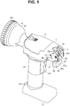
- Fig. 1 is a perspective view illustrating an appearance configuration of a linear member delivery device 1 for an endoscope, relating to the embodiment of the present invention.
- Fig. 2 is a sectional view illustrating a configuration of the linear member delivery device 1 for an endoscope, relating to the embodiment of the present invention.
- Fig. 3 is an enlarged sectional view illustrating the configuration of a nozzle 11, a fitting portion 21 and a switching portion 31 of the linear member delivery device 1 for an endoscope, relating to the embodiment of the present invention.
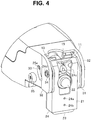
- Fig. 4 is an enlarged perspective view illustrating the appearance configuration of the nozzle 11, the fitting portion 21 and the switching portion 31 of the linear member delivery device 1 for an endoscope, relating to the embodiment of the present invention.
- Fig. 1 is a perspective view illustrating an appearance configuration of a linear member delivery device 1 for an endoscope, relating to the embodiment of the present invention.
- Fig. 2 is a sectional view illustrating a configuration of the linear member delivery device 1 for
- FIG. 5 is a rear perspective view illustrating the appearance configuration of the linear member delivery device 1 for an endoscope, relating to the embodiment of the present invention.
- Fig. 6 is a perspective view illustrating the appearance configuration of the linear member delivery device 1 for an endoscope in a state that a cover 2 is detached, relating to the embodiment of the present invention.
- an electrical connection line is omitted.
- the linear member delivery device 1 for an endoscope is configured including the nozzle 11, the fitting portion 21, the switching portion 31, a holding portion 41, a drive portion 51, a grasping portion 61, a pedestal portion 71, and an operation portion 81.
- the nozzle 11 is configured so as to deliver a cleaning brush B to be described later to a suction cylinder side opening E1 ( Fig. 9 ) of an endoscope E.
- the nozzle 11 is configured by plastic, for example.
- the nozzle 11 includes an inlet 12 configured to introduce the cleaning brush B, an outlet 13 configured to lead out the cleaning brush B, and an insertion path 14 configured to connect the inlet 12 and the outlet 13.
- the insertion path 14 is formed in a cylindrical shape narrowed from the inlet 12 toward the outlet 13.
- the outlet 13 is formed by inclining at least a portion of an end face to a direction orthogonal to a center axis of the nozzle such that the nozzle 11 does not butt into a pipe sleeve E11 of the suction cylinder side opening E1 when an angle of the nozzle 11 is switched.
- one side 15 of an edge of the outlet 13 is inclined to the direction orthogonal to the center axis of the nozzle and formed.
- the fitting portion 21 includes a fitting slit 24c to be described later, and can be fitted to the pipe sleeve E11 in an outward flange shape of the endoscope E.
- the outlet 13 faces the pipe sleeve E11. That is, the fitting portion 21 is fitted to the endoscope E so that the outlet 13 faces the opening of the endoscope E.
- the fitting portion 21 is configured including a connection guide 22, a slide piece 23, a case body 24, and an extension plate 25.
- connection guide 22 is configured by the plastic, for example.
- a body portion 22a is formed into a columnar shape and is formed such that a distal end is narrowed, and a shoulder portion 22b and a base portion 22c are formed into a flange shape.
- a compression spring 23a is externally fitted to the body portion 22a.
- the connection guide 22 is attached to a hollow portion 23b provided in the slide piece 23, the compression spring 23a is pressed to the shoulder portion 22b, and the connection guide 22 is energized in a distal end direction of the connection guide 22.
- thrusting-out is restricted by the base portion 22c being pressed to the case body 24.
- the slide piece 23 is configured by the plastic, for example.
- the slide piece 23 is freely slidably and internally fitted to the case body 24.
- the slide piece 23 is provided with the hollow portion 23b for attaching the connection guide 22.
- the slide piece 23 includes a ball plunger 23d incorporating a ball 23c energized in an extrusion direction by the compression spring 23a.
- the case body 24 is configured by a metal, for example.
- the case body 24 is externally fitted to the slide piece 23.
- the case body 24 includes positioning holes 24a and 24b to which the ball 23c of the ball plunger 23d is to be fitted so that a position in a sliding direction of the slide piece 23 can be switched in two stages.
- the case body 24 includes the fitting slit 24c so as to slide and fit the pipe sleeve E11 of the endoscope E.
- the fitting slit 24c is formed such that the nozzle 11 and the connection guide 22 are exposed.
- the case body 24 includes a turning shaft 24d pivoted to the switching portion 31.
- the fitting portion 21 is freely turnable around the turning shaft 24d.
- the extension plate 25 is extended respectively from both side portions of the case body 24 so as to be connected to the switching portion 31.
- Each extension plate 25 is provided with a pin 25a loosely fitted to a bent long hole 33 of the switching portion 31 so as to restrict a turning range of the fitting portion 21.
- Each extension plate 25 includes positioning holes 25b ( Fig. 12 ) and 25c to which a ball not shown in the figure of a ball plunger 35 (to be described later) is to be fitted so that the position in a turning direction of the fitting portion 21 can be switched in two stages.
- the switching portion 31 connects the fitting portion 21 and the nozzle 11 such that a crossing angle of the suction cylinder side opening E1 and a center axis AN of the nozzle 11 is switched to a plurality of angles in a plurality of stages in the state that the fitting portion 21 is fitted to the endoscope E.
- the switching portion 31 is configured by the plastic, for example.
- the switching portion 31 includes two support plates 32 arranged facing each other so as to hold the fitting portion 21 with each other.
- Each of the two support plates 32 includes a bearing hole 34 configured to pivot the turning shaft 24d of the fitting portion 21, the bent long hole 33 configured to restrict the turning range of the fitting portion 21, and the ball plunger 35 capable of switching a turning angle of the fitting portion 21 in two stages.
- the switching portion 31 can pivot the fitting portion 21 and switch the crossing angle of the suction cylinder side opening E1 and the center axis AN of the nozzle 11 in two stages.
- the holding portion 41 is configured to hold the cleaning brush B such that the crossing angle of an axis AB of the cleaning brush led out from the outlet 13 of the nozzle 11 (in Fig. 2 , the cleaning brush is omitted and only the axis is illustrated) and the center axis AN of the nozzle is in a predetermined range.
- the holding portion 41 is configured including a housing portion 42 and a connection portion 43.
- the housing portion 42 is configured to house the cleaning brush B in a wound state.
- the housing portion 42 is configured by the plastic, for example.
- the housing portion 42 is in a bottomed cylindrical shape, and includes a cylindrical sidewall 42b narrowed toward an opening 42a and a bottom portion 42c ( Fig. 5 ) configured by an attachable and detachable cap.
- a guide 43a (to be described later) is attached.
- the bottom portion 42c includes a ring draw-out hole 42d and a ring hook 42e.
- a ring B4 at a rear end of the cleaning brush B is drawn out from the ring draw-out hole 42d of the bottom portion 42c and hooked to the ring hook 42e.
- the housing portion 42 may not include the ring draw-out hole 42d and the ring hook 42e.
- connection portion 43 is configured to connect the housing portion 42 and the inlet 12 of the nozzle 11.
- the connection portion 43 is configured including the guide 43a and a roller 43b which is a transfer portion.
- the attachable and detachable cover 2 is provided so as to cover an upper part of the connection portion 43, and by detaching the cover 2, the connection portion 43 can be exposed.
- the guide 43a is provided between the roller 43b and the opening 42a of the housing portion 42, and is formed so as to be narrowed from the opening 42a to the roller 43b, in other words, to be widened from the roller 43b to the opening 42a.
- the guide 43a can house a brush B2 of the cleaning brush B, and guides the cleaning brush B sent out to the roller 43b.
- the roller 43b is arranged in the connection portion 43, and is configured to transfer the cleaning brush B at least from the inlet 12 toward the outlet 13.
- the roller 43b is arranged in the connection portion 43. Note that the roller 43b may be arranged inside the insertion path 14 of the nozzle 11 or the housing portion 42.
- the roller 43b is configured by a drive roller 43b1 and a driven roller 43b2 arranged facing each other.
- Each of the drive roller 43b1 and the driven roller 43b2 includes an anti-skid rubber ring 43c on an outer periphery.
- the drive roller 43b1 is connected to a drive shaft 52 of the drive portion 51, and is rotationally driven by the drive portion 51.
- Each of the drive roller 43b1 and the driven roller 43b2 includes two gears 43d that engage with each other at a proximal end.
- the drive roller 43b1 transmits rotating force to the driven roller 43b2 by the two gears 43d, and rotates the driven roller 43b2 in a direction opposite to the drive roller 43b1.
- the drive roller 43b1 and the driven roller 43b2 can transfer the cleaning brush B in a direction from the inlet 12 toward the outlet 13 or in a direction from the outlet 13 toward the inlet 12 by being rotationally driven.
- Fig. 7 is an explanatory diagram describing the configuration of the drive portion 51 and the operation portion 81 of the linear member delivery device 1 for an endoscope, relating to the embodiment of the present invention.
- the drive portion 51 is configured including a motor 53, a control board 54, and a battery 55.
- the motor 53 transmits the rotating force to a gear 53a connected to a motor shaft, a gear 53b that engages with the gear 53a, the drive shaft 52 connected to the gear 53b, and the drive roller 43b1 connected to the drive shaft 52.
- the motor 53 is provided inside the grasping portion 61.
- the motor 53 is connected to the control board 54.
- the motor 53 rotationally drives the roller 43b under control of the control board 54.
- the control board 54 is configured including a circuit configured to control rotation of the motor 53.
- the control board 54 is provided inside the pedestal portion 71.
- the control board 54 is connected to the battery 55 and the operation portion 81.
- the control board 54 supplies electric power of the battery 55 to the motor 53 and rotates the motor 53, according to instruction input inputted through the operation portion 81.
- the battery 55 supplies the electric power to the motor 53 under the control of the control board 54.
- the operation portion 81 is configured including a power switch 82 and an advance/retreat switch 83.
- the operation portion 81 is connected to the control board 54. When an instruction is inputted to the operation portion 81, the instruction input is outputted to the control board 54.
- the power switch 82 is configured to input the instruction of ON/OFF changeover of a power source.
- the advance/retreat switch 83 is configured to input the instruction of advance or retreat of the cleaning brush B, that is, delivery or draw-in of the cleaning brush B.
- Fig. 8 is a diagram illustrating an example of the cleaning brush B of the linear member delivery device 1 for an endoscope, relating to the embodiment of the present invention.
- the cleaning brush B is configured including a shaft B1, the brush B2, a distal end chip B3, and the ring B4.
- the shaft B1 is formed in a thin and long shape by tightly winding a thin metal wire in a coil shape.
- the shaft B1 has a sufficient length enough to be inserted into a conduit of the endoscope E and clean the conduit of the endoscope E by the brush B2 provided on a distal end.
- the shaft B1 is configured having restoration force to return to a straight shape.
- the brush B2 is provided on the distal end of the shaft B1.
- the brush B2 is formed in a size that can pass through while rubbing the conduit of the endoscope E.
- other members such as sponge or rubber that can pass through while rubbing the conduit of the endoscope E may be provided.
- the distal end chip B3 is provided on the distal end of the shaft B1 so that the roller 43b easily draws in the cleaning brush B.
- the ring B4 is provided on a rear end of the shaft B1, and can be hooked to the ring hook 42e of the holding portion 41. Note that the ring B4 may not be provided.
- the shaft B1 is successively bent along the sidewall 42b of the housing portion 42, and is housed in the housing portion 42 in the wound state.
- the cleaning brush B housed in the housing portion 42 in the wound state causes send-out force for sending out the cleaning brush B from the opening 42a of the housing portion 42 to be generated by the restoration force to return to the straight shape.
- the send-out force of the cleaning brush B By the send-out force of the cleaning brush B, the distal end chip B3 is pressed to the roller 43b, and the brush B2 is arranged inside the guide 43a.
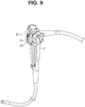
- Fig. 9 is a diagram illustrating an example of the appearance configuration of the endoscope E to which the linear member delivery device 1 for an endoscope is attached, relating to the embodiment of the present invention.
- Fig. 10 is an explanatory diagram describing a state that the nozzle 11 of the linear member delivery device 1 for an endoscope is turned to a universal cord side conduit E12c, relating to the embodiment of the present invention.
- Fig. 11 is an explanatory diagram describing a state that the cleaning brush B of the linear member delivery device 1 for an endoscope is housed in the housing portion 42, relating to the embodiment of the present invention.
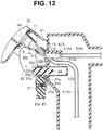
- Fig. 12 is an explanatory diagram describing a state that the nozzle 11 of the linear member delivery device 1 for an endoscope is turned to an insertion portion side conduit E12d, relating to the embodiment of the present invention.
- the endoscope E is configured including the suction cylinder side opening E1 and an air/water feeding cylinder side opening E2.
- a suction cylinder E12 is formed into the cylindrical shape, and includes a universal cord side opening E12a and an insertion portion side opening E12b.
- An air/water feeding cylinder E22 is formed into the cylindrical shape.
- connection guide 22 when the connection guide 22 is inserted into the air/water feeding cylinder E22, the air/water feeding cylinder side opening E2 is pressed to the shoulder portion 22b of the connection guide 22. Then, the shoulder portion 22b of the connection guide 22 is pushed down against energizing force of the compression spring 23a, and the pipe sleeve E11 of the suction cylinder E12 enters an inner side of the case body 24 of the fitting portion 21 from the fitting slit 24c.
- the instruction input is inputted to the control board 54, and the control board 54 makes a current flow to the motor 53, rotates the motor 53, and rotates the roller 43b.
- the roller 43b draws in the distal end chip B3 of the cleaning brush B pressed to the roller 43b, transfers the shaft B1 of the cleaning brush B to the nozzle 11, and delivers the cleaning brush B from the nozzle 11 to the suction cylinder E12.
- the delivered cleaning brush B enters the universal cord side conduit E12c from the universal cord side opening E12a, and rubs and cleans an inside of the universal cord side conduit E12c.
- the control board 54 rotates the motor 53 in the direction opposite to a delivery direction.
- the roller 43b draws in the shaft B1 of the cleaning brush B.
- the shaft B1 of the drawn-in cleaning brush B is bent along the sidewall 42b of the housing portion 42, and is successively housed in the housing portion 42 in the wound state.
- the cleaning brush B can be easily delivered without damaging a cylinder inner wall.
- the cleaning brush B passes through the inside of the suction cylinder E 12 so that the inside of the suction cylinder E 12 can be also cleaned together with cleaning of the universal cord side conduit E12c or the insertion portion side conduit E12d.
- the linear member delivery device 1 for an endoscope delivers the cleaning brush B from an outer side of the suction cylinder side opening E1 of the endoscope E
- the linear member delivery device 1 for an endoscope may be configured to deliver the linear member from the outer side of the other opening of the endoscope.
- the linear member is the cleaning brush B
- the linear member is not limited to the cleaning brush B, and may be a treatment instrument such as a cytodiagnosis brush, grasping forceps or a cannula.
- the present invention is not limited to the above-described embodiment and can be variously changed and modified or the like without changing a subject matter of the present invention.
- a linear member delivery device for an endoscope capable of easily delivering a linear member to a plurality of conduits opened inside a cylinder without damaging a cylinder inner wall can be provided.
Landscapes
- Health & Medical Sciences (AREA)
- Life Sciences & Earth Sciences (AREA)
- Surgery (AREA)
- Biomedical Technology (AREA)
- Medical Informatics (AREA)
- Optics & Photonics (AREA)
- Pathology (AREA)
- Radiology & Medical Imaging (AREA)
- Biophysics (AREA)
- Engineering & Computer Science (AREA)
- Physics & Mathematics (AREA)
- Heart & Thoracic Surgery (AREA)
- Nuclear Medicine, Radiotherapy & Molecular Imaging (AREA)
- Molecular Biology (AREA)
- Animal Behavior & Ethology (AREA)
- General Health & Medical Sciences (AREA)
- Public Health (AREA)
- Veterinary Medicine (AREA)
- Endoscopes (AREA)
- Instruments For Viewing The Inside Of Hollow Bodies (AREA)
Abstract
Description
- The present invention relates to a linear member delivery device for an endoscope.
- Conventionally, there is an adapter configured to lead out a cleaning brush configured by a linear member to an endoscope conduit so as to clean the endoscope conduit. For example, an air/water feeding conduit cleaning adapter disclosed in Japanese Patent Application Laid-Open Publication No.
H05-228107 - However, the conventional air/water feeding conduit cleaning adapter has a problem that a cautious operation is needed so as not to damage a cylinder inner wall when the adapter is inserted into the cylinder.
- Therefore, an object of the present invention is to provide a linear member delivery device for an endoscope capable of easily delivering a linear member to a plurality of conduits opened inside a cylinder without damaging a cylinder inner wall.
- A linear member delivery device for an endoscope of one aspect of the present invention includes: a nozzle including an inlet configured to introduce a linear member, an outlet configured to lead out the linear member, and an insertion path connecting the inlet and the outlet; a fitting portion fitted to an endoscope such that the outlet faces an opening of the endoscope; a holding portion configured to hold the linear member such that a crossing angle of an axis of the linear member led out from the outlet and a center axis of the nozzle is in a predetermined range; and a switching portion connecting the fitting portion and the nozzle such that a crossing angle of the opening of the endoscope and the center axis of the nozzle can be switched to a plurality of angles in a state that the fitting portion is fitted to the endoscope.
-
-
Fig. 1 is a perspective view illustrating an appearance configuration of a linear member delivery device for an endoscope, relating to an embodiment of the present invention; -
Fig. 2 is a sectional view illustrating a configuration of the linear member delivery device for an endoscope, relating to the embodiment of the present invention; -
Fig. 3 is an enlarged sectional view illustrating the configuration of a nozzle, a fitting portion and a switching portion of the linear member delivery device for an endoscope, relating to the embodiment of the present invention; -
Fig. 4 is an enlarged perspective view illustrating the appearance configuration of the nozzle, the fitting portion and the switching portion of the linear member delivery device for an endoscope, relating to the embodiment of the present invention; -
Fig. 5 is a rear perspective view illustrating the appearance configuration of the linear member delivery device for an endoscope, relating to the embodiment of the present invention; -
Fig. 6 is a perspective view illustrating the appearance configuration of the linear member delivery device for an endoscope in a state that a cover is detached, relating to the embodiment of the present invention; -
Fig. 7 is an explanatory diagram describing the configuration of a drive portion and an operation portion of the linear member delivery device for an endoscope, relating to the embodiment of the present invention; -
Fig. 8 is a diagram illustrating an example of a cleaning brush of the linear member delivery device for an endoscope, relating to the embodiment of the present invention; -
Fig. 9 is a diagram illustrating an example of the appearance configuration of the endoscope to which the linear member delivery device for an endoscope is attached, relating to the embodiment of the present invention; -
Fig. 10 is an explanatory diagram describing a state that the nozzle of the linear member delivery device for an endoscope is turned to a universal cord side conduit, relating to the embodiment of the present invention; -
Fig. 11 is an explanatory diagram describing a state that the cleaning brush of the linear member delivery device for an endoscope is housed in a housing portion, relating to the embodiment of the present invention; and -
Fig. 12 is an explanatory diagram describing a state that the nozzle of the linear member delivery device for an endoscope is turned to an insertion portion side conduit, relating to the embodiment of the present invention. - Hereinafter, an embodiment of the present invention will be described with reference to the drawings.
-
Fig. 1 is a perspective view illustrating an appearance configuration of a linearmember delivery device 1 for an endoscope, relating to the embodiment of the present invention.Fig. 2 is a sectional view illustrating a configuration of the linearmember delivery device 1 for an endoscope, relating to the embodiment of the present invention.Fig. 3 is an enlarged sectional view illustrating the configuration of anozzle 11, afitting portion 21 and aswitching portion 31 of the linearmember delivery device 1 for an endoscope, relating to the embodiment of the present invention.Fig. 4 is an enlarged perspective view illustrating the appearance configuration of thenozzle 11, thefitting portion 21 and theswitching portion 31 of the linearmember delivery device 1 for an endoscope, relating to the embodiment of the present invention.Fig. 5 is a rear perspective view illustrating the appearance configuration of the linearmember delivery device 1 for an endoscope, relating to the embodiment of the present invention.Fig. 6 is a perspective view illustrating the appearance configuration of the linearmember delivery device 1 for an endoscope in a state that acover 2 is detached, relating to the embodiment of the present invention. InFig. 2 , an electrical connection line is omitted. - The linear
member delivery device 1 for an endoscope is configured including thenozzle 11, thefitting portion 21, theswitching portion 31, aholding portion 41, adrive portion 51, agrasping portion 61, apedestal portion 71, and anoperation portion 81. - The
nozzle 11 is configured so as to deliver a cleaning brush B to be described later to a suction cylinder side opening E1 (Fig. 9 ) of an endoscope E. Thenozzle 11 is configured by plastic, for example. Thenozzle 11 includes aninlet 12 configured to introduce the cleaning brush B, anoutlet 13 configured to lead out the cleaning brush B, and aninsertion path 14 configured to connect theinlet 12 and theoutlet 13. Theinsertion path 14 is formed in a cylindrical shape narrowed from theinlet 12 toward theoutlet 13. Theoutlet 13 is formed by inclining at least a portion of an end face to a direction orthogonal to a center axis of the nozzle such that thenozzle 11 does not butt into a pipe sleeve E11 of the suction cylinder side opening E1 when an angle of thenozzle 11 is switched. In the present embodiment, oneside 15 of an edge of theoutlet 13 is inclined to the direction orthogonal to the center axis of the nozzle and formed. - The fitting
portion 21 includes afitting slit 24c to be described later, and can be fitted to the pipe sleeve E11 in an outward flange shape of the endoscope E. When thefitting portion 21 is fitted to the pipe sleeve E11, theoutlet 13 faces the pipe sleeve E11. That is, thefitting portion 21 is fitted to the endoscope E so that theoutlet 13 faces the opening of the endoscope E. Thefitting portion 21 is configured including aconnection guide 22, aslide piece 23, acase body 24, and anextension plate 25. - The
connection guide 22 is configured by the plastic, for example. In theconnection guide 22, abody portion 22a is formed into a columnar shape and is formed such that a distal end is narrowed, and ashoulder portion 22b and abase portion 22c are formed into a flange shape. In theconnection guide 22, acompression spring 23a is externally fitted to thebody portion 22a. When theconnection guide 22 is attached to ahollow portion 23b provided in theslide piece 23, thecompression spring 23a is pressed to theshoulder portion 22b, and theconnection guide 22 is energized in a distal end direction of theconnection guide 22. For theconnection guide 22 energized in the distal end direction, thrusting-out is restricted by thebase portion 22c being pressed to thecase body 24. - The
slide piece 23 is configured by the plastic, for example. Theslide piece 23 is freely slidably and internally fitted to thecase body 24. Theslide piece 23 is provided with thehollow portion 23b for attaching theconnection guide 22. Theslide piece 23 includes aball plunger 23d incorporating aball 23c energized in an extrusion direction by thecompression spring 23a. - The
case body 24 is configured by a metal, for example. Thecase body 24 is externally fitted to theslide piece 23. Thecase body 24 includespositioning holes ball 23c of theball plunger 23d is to be fitted so that a position in a sliding direction of theslide piece 23 can be switched in two stages. Thecase body 24 includes thefitting slit 24c so as to slide and fit the pipe sleeve E11 of the endoscope E. Thefitting slit 24c is formed such that thenozzle 11 and theconnection guide 22 are exposed. Thecase body 24 includes a turningshaft 24d pivoted to theswitching portion 31. Thefitting portion 21 is freely turnable around the turningshaft 24d. - The
extension plate 25 is extended respectively from both side portions of thecase body 24 so as to be connected to theswitching portion 31. Eachextension plate 25 is provided with apin 25a loosely fitted to a bentlong hole 33 of theswitching portion 31 so as to restrict a turning range of thefitting portion 21. Eachextension plate 25 includespositioning holes 25b (Fig. 12 ) and 25c to which a ball not shown in the figure of a ball plunger 35 (to be described later) is to be fitted so that the position in a turning direction of thefitting portion 21 can be switched in two stages. - The
switching portion 31 connects thefitting portion 21 and thenozzle 11 such that a crossing angle of the suction cylinder side opening E1 and a center axis AN of thenozzle 11 is switched to a plurality of angles in a plurality of stages in the state that thefitting portion 21 is fitted to the endoscope E. - The
switching portion 31 is configured by the plastic, for example. Theswitching portion 31 includes twosupport plates 32 arranged facing each other so as to hold thefitting portion 21 with each other. Each of the twosupport plates 32 includes abearing hole 34 configured to pivot the turningshaft 24d of thefitting portion 21, the bentlong hole 33 configured to restrict the turning range of thefitting portion 21, and the ball plunger 35 capable of switching a turning angle of thefitting portion 21 in two stages. Thus, theswitching portion 31 can pivot thefitting portion 21 and switch the crossing angle of the suction cylinder side opening E1 and the center axis AN of thenozzle 11 in two stages. - The
holding portion 41 is configured to hold the cleaning brush B such that the crossing angle of an axis AB of the cleaning brush led out from theoutlet 13 of the nozzle 11 (inFig. 2 , the cleaning brush is omitted and only the axis is illustrated) and the center axis AN of the nozzle is in a predetermined range. The holdingportion 41 is configured including ahousing portion 42 and aconnection portion 43. - The
housing portion 42 is configured to house the cleaning brush B in a wound state. Thehousing portion 42 is configured by the plastic, for example. Thehousing portion 42 is in a bottomed cylindrical shape, and includes acylindrical sidewall 42b narrowed toward anopening 42a and abottom portion 42c (Fig. 5 ) configured by an attachable and detachable cap. - To the
opening 42a, aguide 43a (to be described later) is attached. - The
bottom portion 42c includes a ring draw-outhole 42d and aring hook 42e. A ring B4 at a rear end of the cleaning brush B is drawn out from the ring draw-outhole 42d of thebottom portion 42c and hooked to thering hook 42e. Note that thehousing portion 42 may not include the ring draw-outhole 42d and thering hook 42e. - The
connection portion 43 is configured to connect thehousing portion 42 and theinlet 12 of thenozzle 11. Theconnection portion 43 is configured including theguide 43a and aroller 43b which is a transfer portion. As illustrated inFig. 6 , the attachable anddetachable cover 2 is provided so as to cover an upper part of theconnection portion 43, and by detaching thecover 2, theconnection portion 43 can be exposed. - The
guide 43a is provided between theroller 43b and theopening 42a of thehousing portion 42, and is formed so as to be narrowed from theopening 42a to theroller 43b, in other words, to be widened from theroller 43b to theopening 42a. Theguide 43a can house a brush B2 of the cleaning brush B, and guides the cleaning brush B sent out to theroller 43b. - The
roller 43b is arranged in theconnection portion 43, and is configured to transfer the cleaning brush B at least from theinlet 12 toward theoutlet 13. InFig. 2 andFig. 6 , theroller 43b is arranged in theconnection portion 43. Note that theroller 43b may be arranged inside theinsertion path 14 of thenozzle 11 or thehousing portion 42. - The
roller 43b is configured by a drive roller 43b1 and a driven roller 43b2 arranged facing each other. Each of the drive roller 43b1 and the driven roller 43b2 includes ananti-skid rubber ring 43c on an outer periphery. The drive roller 43b1 is connected to adrive shaft 52 of thedrive portion 51, and is rotationally driven by thedrive portion 51. Each of the drive roller 43b1 and the driven roller 43b2 includes twogears 43d that engage with each other at a proximal end. The drive roller 43b1 transmits rotating force to the driven roller 43b2 by the twogears 43d, and rotates the driven roller 43b2 in a direction opposite to the drive roller 43b1. The drive roller 43b1 and the driven roller 43b2 can transfer the cleaning brush B in a direction from theinlet 12 toward theoutlet 13 or in a direction from theoutlet 13 toward theinlet 12 by being rotationally driven. -
Fig. 7 is an explanatory diagram describing the configuration of thedrive portion 51 and theoperation portion 81 of the linearmember delivery device 1 for an endoscope, relating to the embodiment of the present invention. - As illustrated in
Fig. 7 , thedrive portion 51 is configured including amotor 53, acontrol board 54, and abattery 55. - The
motor 53 transmits the rotating force to agear 53a connected to a motor shaft, agear 53b that engages with thegear 53a, thedrive shaft 52 connected to thegear 53b, and the drive roller 43b1 connected to thedrive shaft 52. Themotor 53 is provided inside the graspingportion 61. Themotor 53 is connected to thecontrol board 54. Themotor 53 rotationally drives theroller 43b under control of thecontrol board 54. - The
control board 54 is configured including a circuit configured to control rotation of themotor 53. Thecontrol board 54 is provided inside thepedestal portion 71. Thecontrol board 54 is connected to thebattery 55 and theoperation portion 81. Thecontrol board 54 supplies electric power of thebattery 55 to themotor 53 and rotates themotor 53, according to instruction input inputted through theoperation portion 81. - The
battery 55 supplies the electric power to themotor 53 under the control of thecontrol board 54. - The
operation portion 81 is configured including apower switch 82 and an advance/retreat switch 83. Theoperation portion 81 is connected to thecontrol board 54. When an instruction is inputted to theoperation portion 81, the instruction input is outputted to thecontrol board 54. - The
power switch 82 is configured to input the instruction of ON/OFF changeover of a power source. - The advance/
retreat switch 83 is configured to input the instruction of advance or retreat of the cleaning brush B, that is, delivery or draw-in of the cleaning brush B. - Next, the cleaning brush B housed in the linear
member delivery device 1 for an endoscope and delivered from the linearmember delivery device 1 for an endoscope will be described. -
Fig. 8 is a diagram illustrating an example of the cleaning brush B of the linearmember delivery device 1 for an endoscope, relating to the embodiment of the present invention. - The cleaning brush B is configured including a shaft B1, the brush B2, a distal end chip B3, and the ring B4.
- The shaft B1 is formed in a thin and long shape by tightly winding a thin metal wire in a coil shape. The shaft B1 has a sufficient length enough to be inserted into a conduit of the endoscope E and clean the conduit of the endoscope E by the brush B2 provided on a distal end. The shaft B1 is configured having restoration force to return to a straight shape.
- The brush B2 is provided on the distal end of the shaft B1. The brush B2 is formed in a size that can pass through while rubbing the conduit of the endoscope E. Note that, instead of the brush B2, other members such as sponge or rubber that can pass through while rubbing the conduit of the endoscope E may be provided.
- The distal end chip B3 is provided on the distal end of the shaft B1 so that the
roller 43b easily draws in the cleaning brush B. - The ring B4 is provided on a rear end of the shaft B1, and can be hooked to the
ring hook 42e of the holdingportion 41. Note that the ring B4 may not be provided. - When the cleaning brush B is drawn into the
housing portion 42 by the rotation of theroller 43b, the shaft B1 is successively bent along thesidewall 42b of thehousing portion 42, and is housed in thehousing portion 42 in the wound state. - The cleaning brush B housed in the
housing portion 42 in the wound state causes send-out force for sending out the cleaning brush B from theopening 42a of thehousing portion 42 to be generated by the restoration force to return to the straight shape. By the send-out force of the cleaning brush B, the distal end chip B3 is pressed to theroller 43b, and the brush B2 is arranged inside theguide 43a. - Subsequently, the operation of the linear
member delivery device 1 for an endoscope will be described. -
Fig. 9 is a diagram illustrating an example of the appearance configuration of the endoscope E to which the linearmember delivery device 1 for an endoscope is attached, relating to the embodiment of the present invention.Fig. 10 is an explanatory diagram describing a state that thenozzle 11 of the linearmember delivery device 1 for an endoscope is turned to a universal cord side conduit E12c, relating to the embodiment of the present invention.Fig. 11 is an explanatory diagram describing a state that the cleaning brush B of the linearmember delivery device 1 for an endoscope is housed in thehousing portion 42, relating to the embodiment of the present invention.Fig. 12 is an explanatory diagram describing a state that thenozzle 11 of the linearmember delivery device 1 for an endoscope is turned to an insertion portion side conduit E12d, relating to the embodiment of the present invention. - As illustrated in
Fig. 9 , the endoscope E is configured including the suction cylinder side opening E1 and an air/water feeding cylinder side opening E2. A suction cylinder E12 is formed into the cylindrical shape, and includes a universal cord side opening E12a and an insertion portion side opening E12b. An air/water feeding cylinder E22 is formed into the cylindrical shape. - As illustrated in
Fig. 10 , when theconnection guide 22 is inserted into the air/water feeding cylinder E22, the air/water feeding cylinder side opening E2 is pressed to theshoulder portion 22b of theconnection guide 22. Then, theshoulder portion 22b of theconnection guide 22 is pushed down against energizing force of thecompression spring 23a, and the pipe sleeve E11 of the suction cylinder E12 enters an inner side of thecase body 24 of thefitting portion 21 from thefitting slit 24c. Next, when the endoscope E is slid in a direction from the suction cylinder E12 to the air/water feeding cylinder E22, theslide piece 23 is slid together with theconnection guide 22 inserted into the endoscope E, and theball 23c of theball plunger 23d is fitted to thepositioning hole 24b of thecase body 24 and positioned. Thus, the pipe sleeve E11 of the suction cylinder E12 is slid and fitted to thecase body 24, and thenozzle 11 is turned to the universal cord side opening E12a inside the suction cylinder E12. - When the power source is turned to an ON state by the
power switch 82 and the instruction to deliver the cleaning brush B is inputted by the advance/retreat switch 83, the instruction input is inputted to thecontrol board 54, and thecontrol board 54 makes a current flow to themotor 53, rotates themotor 53, and rotates theroller 43b. Then, theroller 43b draws in the distal end chip B3 of the cleaning brush B pressed to theroller 43b, transfers the shaft B1 of the cleaning brush B to thenozzle 11, and delivers the cleaning brush B from thenozzle 11 to the suction cylinder E12. The delivered cleaning brush B enters the universal cord side conduit E12c from the universal cord side opening E12a, and rubs and cleans an inside of the universal cord side conduit E12c. - When the instruction to draw in the cleaning brush B is inputted by the advance/
retreat switch 83, thecontrol board 54 rotates themotor 53 in the direction opposite to a delivery direction. When themotor 53 is rotated, theroller 43b draws in the shaft B1 of the cleaning brush B. As illustrated inFig. 11 , the shaft B1 of the drawn-in cleaning brush B is bent along thesidewall 42b of thehousing portion 42, and is successively housed in thehousing portion 42 in the wound state. When the distal end chip B3 at the distal end of the cleaning brush B passes through theroller 43b, the draw-in of the cleaning brush B is completed. - As illustrated in
Fig. 12 , when thefitting portion 21 is turned around the turningshaft 24d, the ball not shown in the figure of theball plunger 35 of the switchingportion 31 is fitted to thepositioning hole 25b of theextension plate 25 of thefitting portion 21, and thenozzle 11 is turned to the insertion portion side opening E12b inside thesuction cylinder E 12. When the instruction for delivering the cleaning brush B is inputted by the advance/retreat switch 83, the cleaning brush B enters the insertion portion side conduit E12d from the insertion portion side opening E12b, and cleans the inside of the insertion portion side conduit E12d. - According to the embodiment, to the universal cord side conduit E12c and the insertion portion side conduit E12d opened inside the suction cylinder E12, the cleaning brush B can be easily delivered without damaging a cylinder inner wall.
- According to the embodiment, the cleaning brush B passes through the inside of the
suction cylinder E 12 so that the inside of thesuction cylinder E 12 can be also cleaned together with cleaning of the universal cord side conduit E12c or the insertion portion side conduit E12d. - Note that, in the embodiment, the example is described in which the linear
member delivery device 1 for an endoscope delivers the cleaning brush B from an outer side of the suction cylinder side opening E1 of the endoscope E, however, the linearmember delivery device 1 for an endoscope may be configured to deliver the linear member from the outer side of the other opening of the endoscope. - Note that, in the embodiment, the example is described in which the linear member is the cleaning brush B, however, the linear member is not limited to the cleaning brush B, and may be a treatment instrument such as a cytodiagnosis brush, grasping forceps or a cannula.
- The present invention is not limited to the above-described embodiment and can be variously changed and modified or the like without changing a subject matter of the present invention.
- According to the present invention, a linear member delivery device for an endoscope capable of easily delivering a linear member to a plurality of conduits opened inside a cylinder without damaging a cylinder inner wall can be provided.
- The present application is filed based on and claiming priority from Japanese Patent Application No.
2016-014472
Claims (5)
- A linear member delivery device for an endoscope comprising:a nozzle including an inlet configured to introduce a linear member, an outlet configured to lead out the linear member, and an insertion path connecting the inlet and the outlet;a fitting portion fitted to an endoscope such that the outlet faces an opening of the endoscope;a holding portion configured to hold the linear member such that a crossing angle of an axis of the linear member led out from the outlet and a center axis of the nozzle is in a predetermined range; anda switching portion connecting the fitting portion and the nozzle such that a crossing angle of the opening of the endoscope and the center axis of the nozzle can be switched to a plurality of angles in a state that the fitting portion is fitted to the endoscope.
- The linear member delivery device for the endoscope according to claim 1,
wherein the switching portion switches the crossing angle of the opening of the endoscope and the center axis of the nozzle in a plurality of stages, and
the outlet is formed by inclining at least a portion of an end face to a direction orthogonal to the center axis of the nozzle. - The linear member delivery device for the endoscope according to claim 1,
wherein the holding portion includes:a housing portion where the linear member is housed in a wound state; anda connection portion configured to connect the housing portion and the inlet. - The linear member delivery device for the endoscope according to claim 1, comprising a transfer portion arranged in the insertion path or the holding portion and configured to transfer the linear member at least from the inlet toward the outlet.
- The linear member delivery device for the endoscope according to claim 1, wherein the fitting portion is fitted to a suction cylinder of the endoscope.
Applications Claiming Priority (2)
| Application Number | Priority Date | Filing Date | Title |
|---|---|---|---|
| JP2016014472 | 2016-01-28 | ||
| PCT/JP2016/079091 WO2017130465A1 (en) | 2016-01-28 | 2016-09-30 | Linear member delivering device for endoscope |
Publications (2)
| Publication Number | Publication Date |
|---|---|
| EP3241486A1 true EP3241486A1 (en) | 2017-11-08 |
| EP3241486A4 EP3241486A4 (en) | 2018-11-21 |
Family
ID=59397558
Family Applications (1)
| Application Number | Title | Priority Date | Filing Date |
|---|---|---|---|
| EP16869375.2A Withdrawn EP3241486A4 (en) | 2016-01-28 | 2016-09-30 | Linear member delivering device for endoscope |
Country Status (5)
| Country | Link |
|---|---|
| US (1) | US10194784B2 (en) |
| EP (1) | EP3241486A4 (en) |
| JP (1) | JP6113390B1 (en) |
| CN (1) | CN107405065B (en) |
| WO (1) | WO2017130465A1 (en) |
Families Citing this family (4)
| Publication number | Priority date | Publication date | Assignee | Title |
|---|---|---|---|---|
| US10716623B2 (en) * | 2016-05-05 | 2020-07-21 | Covidien Lp | Bronchoscope coupler |
| JP6604666B2 (en) * | 2018-01-31 | 2019-11-13 | 興研株式会社 | Endoscope cleaning device |
| US20200178783A1 (en) * | 2018-12-05 | 2020-06-11 | Asp Global Manufacturing Gmbh | Apparatus and system for guiding a cleaning implement and a method of use thereof |
| USD989299S1 (en) * | 2021-07-23 | 2023-06-13 | Intuitive Surgical Operations, Inc. | Connector assembly for a surgical instrument |
Family Cites Families (13)
| Publication number | Priority date | Publication date | Assignee | Title |
|---|---|---|---|---|
| EP0075188B1 (en) | 1981-09-17 | 1987-11-19 | Olympus Optical Co., Ltd. | A suction device for an endoscope |
| JPS5846933A (en) * | 1981-09-17 | 1983-03-18 | オリンパス光学工業株式会社 | Apparatus for washing suction pipeline of endoscope |
| JPH05228107A (en) | 1992-02-19 | 1993-09-07 | Asahi Optical Co Ltd | Air feed and water feed pipeline cleaning means for endoscope |
| JP4307831B2 (en) * | 2002-12-27 | 2009-08-05 | オリンパス株式会社 | Endoscope pipe cleaning device |
| JP4144666B2 (en) * | 2003-08-11 | 2008-09-03 | 興研株式会社 | Endoscope cleaning brush insertion guide and method of using the same |
| JP2008161383A (en) * | 2006-12-27 | 2008-07-17 | Olympus Medical Systems Corp | Endoscope cleaning disinfection device |
| JP5032272B2 (en) * | 2007-11-12 | 2012-09-26 | オリンパスメディカルシステムズ株式会社 | Endoscope cleaning disinfection device |
| JP5220435B2 (en) * | 2008-02-20 | 2013-06-26 | オリンパスメディカルシステムズ株式会社 | Cleaning tube and endoscope cleaning / disinfecting device |
| US9126241B2 (en) * | 2009-11-20 | 2015-09-08 | Ali Waqar Majeed | Cleaning apparatus |
| JP2011120788A (en) * | 2009-12-11 | 2011-06-23 | Koken Ltd | Guide of endoscope washing brush |
| EP2962619A4 (en) * | 2013-02-27 | 2017-01-11 | Olympus Corporation | Insertion/removal-support tool for endoscopic instrument |
| JP2016014472A (en) | 2014-06-13 | 2016-01-28 | 日本精工株式会社 | Snap ring |
| KR101675589B1 (en) * | 2015-02-09 | 2016-11-14 | 이동규 | Endoscope cleaner, endoscope cleaner with replacable casette, and brush casette for cleaning endoscope |
-
2016
- 2016-09-30 EP EP16869375.2A patent/EP3241486A4/en not_active Withdrawn
- 2016-09-30 CN CN201680004155.XA patent/CN107405065B/en active Active
- 2016-09-30 JP JP2017502280A patent/JP6113390B1/en active Active
- 2016-09-30 WO PCT/JP2016/079091 patent/WO2017130465A1/en not_active Ceased
-
2017
- 2017-06-12 US US15/619,603 patent/US10194784B2/en active Active
Also Published As
| Publication number | Publication date |
|---|---|
| US10194784B2 (en) | 2019-02-05 |
| CN107405065A (en) | 2017-11-28 |
| WO2017130465A1 (en) | 2017-08-03 |
| CN107405065B (en) | 2019-08-20 |
| JP6113390B1 (en) | 2017-04-12 |
| JPWO2017130465A1 (en) | 2018-02-01 |
| US20170273544A1 (en) | 2017-09-28 |
| EP3241486A4 (en) | 2018-11-21 |
Similar Documents
| Publication | Publication Date | Title |
|---|---|---|
| EP3241486A1 (en) | Linear member delivering device for endoscope | |
| JP3658130B2 (en) | Pipe-line separation type endoscopic device | |
| CN102355846B (en) | Endoscope for treatment | |
| EP3854292A1 (en) | Video endoscope with flexible tip | |
| CN109922705B (en) | Endoscope, endoscope wire installation method and endoscope wire removal method | |
| JP2018110924A (en) | Endoscope cap | |
| WO2006095336A2 (en) | Handheld portable medical viewing assembly for displaying medical images during endotracheal intubation, and intubation stylet for use therewith | |
| EP2016914A3 (en) | Insertion assisting device and endoscope apparatus | |
| JP2010508050A (en) | Joint between medical handpiece and supply hose | |
| JP2013523372A (en) | Lens protector for endoscope equipment | |
| WO2015024459A1 (en) | Endoscope apparatus | |
| US20190305474A1 (en) | Connector unit | |
| US8016753B2 (en) | Endoscope | |
| CN114098595B (en) | Front cover removal jig | |
| JP2021518231A (en) | Endoscope equipment and related methods | |
| CN112568859B (en) | Liquid feeding device, liquid feeding tube and liquid feeding device main body for endoscope | |
| US9700184B2 (en) | Floor care appliance | |
| US9700377B2 (en) | Surgical robot for changing position of surgical equipment | |
| EP3225152B1 (en) | Linear member transfer device | |
| CN216702509U (en) | Butt joint suitable for disposable endoscope | |
| CN105813539A (en) | Retaining mechanism for endoscope guide member, and endoscope | |
| US20200324421A1 (en) | End effector device, robotic hand device, and robotic device | |
| JPH10258028A (en) | Pipeline separate type endoscope apparatus | |
| JP4020321B2 (en) | Pipe-line separation type endoscopic device | |
| CN221903551U (en) | Endoscopic detector for lumen instrument |
Legal Events
| Date | Code | Title | Description |
|---|---|---|---|
| STAA | Information on the status of an ep patent application or granted ep patent |
Free format text: STATUS: UNKNOWN |
|
| STAA | Information on the status of an ep patent application or granted ep patent |
Free format text: STATUS: THE INTERNATIONAL PUBLICATION HAS BEEN MADE |
|
| PUAI | Public reference made under article 153(3) epc to a published international application that has entered the european phase |
Free format text: ORIGINAL CODE: 0009012 |
|
| STAA | Information on the status of an ep patent application or granted ep patent |
Free format text: STATUS: REQUEST FOR EXAMINATION WAS MADE |
|
| 17P | Request for examination filed |
Effective date: 20170608 |
|
| AK | Designated contracting states |
Kind code of ref document: A1 Designated state(s): AL AT BE BG CH CY CZ DE DK EE ES FI FR GB GR HR HU IE IS IT LI LT LU LV MC MK MT NL NO PL PT RO RS SE SI SK SM TR |
|
| AX | Request for extension of the european patent |
Extension state: BA ME |
|
| RIN1 | Information on inventor provided before grant (corrected) |
Inventor name: IWASAKI, TOMOKAZU Inventor name: ONISHI, HIDETO Inventor name: KIM, YOUNG CHUNG |
|
| A4 | Supplementary search report drawn up and despatched |
Effective date: 20181018 |
|
| RIC1 | Information provided on ipc code assigned before grant |
Ipc: A61B 1/00 20060101ALI20181012BHEP Ipc: A61B 1/12 20060101AFI20181012BHEP Ipc: B08B 9/043 20060101ALI20181012BHEP Ipc: A61B 90/70 20160101ALN20181012BHEP |
|
| RIN1 | Information on inventor provided before grant (corrected) |
Inventor name: KIM, YOUNG CHUNG Inventor name: ONISHI, HIDETO Inventor name: IWASAKI, TOMOKAZU |
|
| DAV | Request for validation of the european patent (deleted) | ||
| DAX | Request for extension of the european patent (deleted) | ||
| GRAP | Despatch of communication of intention to grant a patent |
Free format text: ORIGINAL CODE: EPIDOSNIGR1 |
|
| STAA | Information on the status of an ep patent application or granted ep patent |
Free format text: STATUS: GRANT OF PATENT IS INTENDED |
|
| RIC1 | Information provided on ipc code assigned before grant |
Ipc: A61B 90/70 20160101ALN20201013BHEP Ipc: A61B 1/12 20060101AFI20201013BHEP Ipc: A61B 1/00 20060101ALI20201013BHEP Ipc: B08B 9/043 20060101ALI20201013BHEP |
|
| INTG | Intention to grant announced |
Effective date: 20201030 |
|
| RIC1 | Information provided on ipc code assigned before grant |
Ipc: B08B 9/043 20060101ALI20201019BHEP Ipc: A61B 90/70 20160101ALN20201019BHEP Ipc: A61B 1/00 20060101ALI20201019BHEP Ipc: A61B 1/12 20060101AFI20201019BHEP |
|
| STAA | Information on the status of an ep patent application or granted ep patent |
Free format text: STATUS: THE APPLICATION IS DEEMED TO BE WITHDRAWN |
|
| 18D | Application deemed to be withdrawn |
Effective date: 20210310 |