EP3240727B1 - Seat suspension installation method and passenger seat - Google Patents
Seat suspension installation method and passenger seat Download PDFInfo
- Publication number
- EP3240727B1 EP3240727B1 EP14824947.7A EP14824947A EP3240727B1 EP 3240727 B1 EP3240727 B1 EP 3240727B1 EP 14824947 A EP14824947 A EP 14824947A EP 3240727 B1 EP3240727 B1 EP 3240727B1
- Authority
- EP
- European Patent Office
- Prior art keywords
- seat
- side frame
- seat suspension
- suspension layer
- frame member
- Prior art date
- Legal status (The legal status is an assumption and is not a legal conclusion. Google has not performed a legal analysis and makes no representation as to the accuracy of the status listed.)
- Active
Links
- 239000000725 suspension Substances 0.000 title claims description 141
- 238000000034 method Methods 0.000 title claims description 39
- 238000009434 installation Methods 0.000 title claims description 23
- 239000004744 fabric Substances 0.000 claims description 19
- 239000000463 material Substances 0.000 claims description 6
- 239000002184 metal Substances 0.000 claims description 5
- 239000002131 composite material Substances 0.000 claims description 4
- 239000004033 plastic Substances 0.000 claims description 4
- 238000012423 maintenance Methods 0.000 description 6
- 230000033001 locomotion Effects 0.000 description 4
- 238000009826 distribution Methods 0.000 description 3
- 230000010354 integration Effects 0.000 description 3
- 238000004519 manufacturing process Methods 0.000 description 3
- 230000013011 mating Effects 0.000 description 3
- 239000004677 Nylon Substances 0.000 description 2
- 229920001778 nylon Polymers 0.000 description 2
- 230000000712 assembly Effects 0.000 description 1
- 238000000429 assembly Methods 0.000 description 1
- 238000010276 construction Methods 0.000 description 1
- 239000006260 foam Substances 0.000 description 1
- 239000012528 membrane Substances 0.000 description 1
- 238000000465 moulding Methods 0.000 description 1
- 210000003205 muscle Anatomy 0.000 description 1
- 229920000728 polyester Polymers 0.000 description 1
- 230000003014 reinforcing effect Effects 0.000 description 1
- 230000000717 retained effect Effects 0.000 description 1
- 238000004513 sizing Methods 0.000 description 1
- 230000009466 transformation Effects 0.000 description 1
Images





Classifications
-
- B—PERFORMING OPERATIONS; TRANSPORTING
- B64—AIRCRAFT; AVIATION; COSMONAUTICS
- B64D—EQUIPMENT FOR FITTING IN OR TO AIRCRAFT; FLIGHT SUITS; PARACHUTES; ARRANGEMENT OR MOUNTING OF POWER PLANTS OR PROPULSION TRANSMISSIONS IN AIRCRAFT
- B64D11/00—Passenger or crew accommodation; Flight-deck installations not otherwise provided for
- B64D11/06—Arrangements of seats, or adaptations or details specially adapted for aircraft seats
- B64D11/0647—Seats characterised by special upholstery or cushioning features
-
- B—PERFORMING OPERATIONS; TRANSPORTING
- B64—AIRCRAFT; AVIATION; COSMONAUTICS
- B64D—EQUIPMENT FOR FITTING IN OR TO AIRCRAFT; FLIGHT SUITS; PARACHUTES; ARRANGEMENT OR MOUNTING OF POWER PLANTS OR PROPULSION TRANSMISSIONS IN AIRCRAFT
- B64D11/00—Passenger or crew accommodation; Flight-deck installations not otherwise provided for
- B64D11/06—Arrangements of seats, or adaptations or details specially adapted for aircraft seats
-
- Y—GENERAL TAGGING OF NEW TECHNOLOGICAL DEVELOPMENTS; GENERAL TAGGING OF CROSS-SECTIONAL TECHNOLOGIES SPANNING OVER SEVERAL SECTIONS OF THE IPC; TECHNICAL SUBJECTS COVERED BY FORMER USPC CROSS-REFERENCE ART COLLECTIONS [XRACs] AND DIGESTS
- Y02—TECHNOLOGIES OR APPLICATIONS FOR MITIGATION OR ADAPTATION AGAINST CLIMATE CHANGE
- Y02T—CLIMATE CHANGE MITIGATION TECHNOLOGIES RELATED TO TRANSPORTATION
- Y02T50/00—Aeronautics or air transport
- Y02T50/40—Weight reduction
Definitions
- the present invention relates generally to a seat suspension installation method and to a passenger seat.
- Backrest support of aviation seating system is traditionally made from rigid diaphragm, the design consideration of which has been primarily due to efforts in meeting flammability and load bearing compliance to aircraft interiors' cabin safety regulations.
- the rigid diaphragm construction increases the weight to the entire seating system, and therefore increases the associated operational costs from heavier payload.
- the stiff nature of this form of solution may cause passenger discomfort, which is highly undesirable especially for long flight.
- the compensation usually comes in the form of thicker backrest cushion. This in turn adds on cushion weight and is poorer aesthetically as well.
- suspension fabric material has been introduced to backrest supports.
- Such integration reduces overall seating system weight by reducing the amount of foams in the backrest cushion.
- the stretchable suspension fabric may be poorer in maintaining its elasticity in fatigue aspect, and this requires replacement as part of maintenance effort. Furthermore, the fabric is unable to hold required contour due to its inherent properties, unlike sheet metal solutions.
- the existing installation methods include a "wrapped-around" method.
- Fig. 1 illustrates the wrapped-around installation 100, wherein the suspension fabric 102 is wrapped around a seatback frame 104. Using the wrapped-around method, it may be difficult to install or remove the suspension fabric assemblies, and their installation /removal processes may induce high stress on the seatback frame.
- the wrapped-around method using a suspension fabric provided with zippers thereon may make it easier to install or remove the suspension fabric than the wrapped-around method of Fig. 1 using a suspension fabric without zippers, but the reliability of the system is subject to zipper's performances. In addition, such installation may not optimize the space utilization between the seatback frame.
- EP 0 738 490 describes a plane for the seat of armchairs, divans, chairs and similar of the type including a framework for the support of a plurality of belts forming the plane of the seat, where said framework includes two lateral sections that show a protruding tongue, provided with fixing U shaped elements inserted around said tongue, while the belt passes outside said U shaped sections and is then folded up backwards and inserted between said tongue and said U shaped element so that the tension exerted by said belt presses said U shaped element in order to block the end of said belt against said tongue.
- Various embodiments provide a method for installing a seat suspension player according to claim 1.
- Various embodiments provide a passenger seat according to claim 11.
- Various embodiments provide a method for installing a seat suspension onto a seat frame in an easier and space-saving manner.
- the method of various embodiments not only can be used during manufacturing, but also can be used during maintenance.
- exemplary is used herein to mean “serving as an example, instance, or illustration”. Any embodiment or design described herein as “exemplary” is not necessarily to be construed as preferred or advantageous over other embodiments or designs.
- the seat suspension installation method can be performed in various orientations, and thus it should be understood that the terms “side”, “top”, “bottom”, “left”, “right”, “front”, “back”, “forward”, “rear” etc., when used in the following description are used for convenience and to aid understanding of relative positions or directions, and not intended to limit the seat suspension installation method.
- Fig. 2 shows a flowchart 200 illustrating a method for installing a seat suspension.
- the seat frame may include a first side frame member and a second side frame member opposed to and spaced apart from each other.
- a retainer on a first side of the seat suspension is moved in a direction substantially perpendicular to a plane defined by the first and second side frame members for fastening onto a support member on the first side frame member.
- a retainer on the second side of the seat suspension is moved in the direction substantially perpendicular to the plane defined by the first and second side frame members for fastening onto a support member on the second side frame member.
- the second side of the seat suspension is opposed to and spaced apart from the first side of the seat suspension.
- the movement of the retainer on the first side of the seat suspension may include moving a plurality of retainers on the first side of the seat suspension in the direction substantially perpendicular to the plane defined by the first and second side frame members for fastening onto a plurality of support members on the first side frame member.
- the first side frame member may include a plurality of portions at an angle with each other, and the plurality of support members are respectively located on the plurality of portions of the first side frame member.
- the first side frame member may include a plurality of straight portions at an angle with each other, and the plurality of support members are respectively located on the plurality of portions of the first side frame member.
- the first side frame member may be of a curved shape, and the plurality of support members may be located corresponding to the curved shape of the first side frame member.
- the movement of the retainer on the second side of the seat suspension may include moving a plurality of retainers on the second side of the seat suspension in the direction substantially perpendicular to the plane defined by the first and second side frame members for fastening onto a plurality of support members on the second side frame member.
- the second side frame member may include a plurality of portions at an angle with each other, and the plurality of support members are respectively located on the plurality of portions of the second side frame member.
- the second side frame member may include a plurality of straight portions at an angle with each other, and the plurality of support members are respectively located on the plurality of portions of the second side frame member.
- the second side frame member may be of a curved shape, and the plurality of support members may be located corresponding to the curved shape of the second side frame member.
- the installation method may include stretching the seat suspension from the first side frame member towards the second side frame member.
- the seat suspension may be stretched towards the second side frame member after the first side of the seat suspension is installed on the first side frame member, so as to install the second side of the seat suspension onto the second side frame member.
- Fig. 3 shows a schematic drawing 300 illustrating a seat frame and a seat suspension to be installed onto the seat frame.
- Fig. 3 shows a seat suspension 310 and a seat frame 320.
- the seat suspension 310 may be a suspension fabric which is tailored to match seat back geometry and contour.
- the seat suspension 310 may also be a seat suspension membrane or sheet made of any suitable material.
- a first side 302 and a second side 304 of the seat suspension 310 are opposed to and spaced apart from each other.
- the first side 302 and the second side 304 are illustrated as the right side and the left side of the seat suspension, when the seat suspension is oriented upright in its installed state. It is understood that the first side 302 and the second side 304 may also be the top side and the bottom side of the seat suspension in its upright orientation.
- a retainer 306 may be provided on the first side 302, and a retainer 308 may be provided on the second side 304.
- the retainers 306, 308 may be sewn along the first side 302 and the second side 304, e.g. using the sewn threads as illustrated in Fig. 3 .
- Each of the retainers 306, 308 may include an elongated body extending along the first side 302 or the second side 304 of the seat suspension 310.
- the retainers 306, 308 may include J-shaped or C-shaped retainers.
- the J-shaped retainers 306, 308 are shown in Fig. 3 having an elongated body with a J-shaped cross-section.
- the retainers 306, 308 may be made of plastic, metal or composite.
- the retainers may be made of any other material having sufficient strength for the retainers to hold the seat suspension, when the seat suspension is loaded with or without passenger load.
- the retainers 306, 308 are sewn along the first side 302 and the second side 304 of the seat suspension 310, respectively.
- the retainers 306, 308 may be attached or fixed to the first side 302 and the second side 304 using other suitable means, such as heat staking or integrally forming or molding the retainers 306, 308 to the seat suspension 310.
- the seat frame 320 is a seat back frame.
- the seat frame 320 includes a first side frame member 322 and a second side frame member 324 opposed to and spaced apart from each other.
- the first side frame member 322 and the second side frame member 324 are illustrated as the right side frame member and the left side frame member of the seat frame 320 in its upright orientation. It is understood that the first side frame member 322 and the second side frame member 324 may also be the top side frame member and the bottom side frame member of the seat frame for the seat suspension 310 to be installed in such a manner.
- a support member 326 may be located on the first side frame member 322, and a support member 328 may be located on the second side frame member 324.
- the support members 326, 328 may be brackets or strips mounted on or attached to the first and second side frame members 322, 324, respectively.
- the support members 326, 328 may be of any shape that fits the shape of the female portion of the retainers 306, 308.
- the support members 326, 328 may be arranged to protrude substantially perpendicularly from the plane 332 defined by the first and second side frame members 322, 324.
- the support members 326, 328 are shown to protrude outward from the plane 332 of the seat frame 320 and extend backwardly.
- the support members 326, 328 may be made of plastic, metal, composite, or any suitable material that is strong enough to hold the load received by the seat suspension 310, with or without passenger load.
- the seat suspension 310 is installed onto the front side of the seat frame 320 in a rear-facing direction. It is understood that the seat suspension 310 may also be installed onto the back side of the seat frame in a forward-facing direction in other embodiments.
- the retainer 306 on the first side 302 of the seat suspension 310 is moved in the direction 330 substantially perpendicular to the plane 332 defined by the first and second side frame members 322, 324, for fastening onto the support member 326 on the first side frame member 322.
- the seat suspension 310 may be stretched towards the second side frame member 324 so that the retainer 308 on the second side 304 of the seat suspension 310 is sufficiently close to the support member 328 on the second side frame member 324.
- the seat suspension 310 may be stretched using a loop design and a rod, as will be described in more detail below.
- the retainer 308 on the second side 304 of the seat suspension 310 is moved in the direction 330 substantially perpendicular to the plane 332 so as to be fastened onto the support member 328 on the second side frame member 324. In this manner, the seat suspension 310 is installed onto the seat frame 320.
- Fig. 4 shows a schematic drawing illustrating a passenger seat 400 having a seat suspension installed onto a seat frame.
- the passenger seat 400 may include the seat suspension 310 and the seat frame 320 illustrated in Fig. 3 in an installed state, wherein the second side 304 of the seat suspension 310 installed onto the second side frame member 324 are shown.
- the support member 328 may protrude substantially perpendicularly from the plane 332 defined by the first and second side frame members of the seat frame 320.
- the support member 328 is shown to protrude outward and backward from the second seat frame member 324.
- the retainer 308 is fastened or latched onto the support member 328 on the second side frame member 324 in the direction 330 substantially perpendicular to the plane 332 defined by the first and second side frames of the seat frame 320.
- the retainer 308 installed in such a manner may be received on the mounting provision on the seat frame, e.g. on the support member 328 protruding substantially perpendicularly from the plane 332 as shown in Fig. 4 .
- the retainer 308 may include a pair of apposing edges connected by a connecting edge, wherein the retainer 308 is fastened to the support member 328 such that the pair of apposing edges extends in the direction 330 substantially perpendicular to the plane 332 defined by the first and second side frame members.
- retainers 306, 308 are J-shaped retainers as illustrated above, it is understood that the retainers may be of any suitable shape or form which is able to be fastened onto the seat frame, and may be of any suitable geometric sizing to allow continuous latching and quick installation onto the seat frame.
- the integration of the seat suspension and the seat frame is realized using retainers and support members with rear-facing engagement. This may ensure that the seat suspension conforms to the shape and contour of the seat back frame, and therefore the intent of creating comfortable sitting position at the interface to passenger is retained throughout the servicing operation after the seats are installed in aircraft.
- seat suspension may be easier to be installed during maintenance, in which situation there may be limited space at the side of an aircraft seat, e.g. for an aircraft seat next to the window.
- the perpendicular movement of the retainers is advantageous in that less space is needed on the sides of the seat frame.
- the retainers can be flat with a small thickness and yet have a good strength (e.g., in J shape). Whereas for clip-on designs in which clips/retainers move in from the side of the seat frame, the clips/retainers have to protrude the side before clip-on, requiring more space on the sides of the seat frame and requiring thick clips/retainers to clip onto the side of the seat frame. Further, compared to the clip-on designs in which clips/retainers move in from the side of the seat frame, the installation method is advantageous in that fastening of retainers may be more secure, since the retainers fastened in the manner are less likely to dislodge during use.
- the method install the seat suspension on either the front side or the back side of the seat frame and also provide additional usable space between the seat frame that may be used for seatback amenity or stowage.
- the seat suspension is installed from the front side of the seat frame, additional space at the backside of the seat frame is available and may be used for seatback amenity or stowage.
- retainers may ensure that the stretch load is evenly distributed along the two longitudinal sides of the seat back frame. This eliminates the existing requirement of locally reinforcing the seat back frame where the suspension fabric is connected.
- the thread sew lines, connecting the seat suspension and retainers, are designed for similar consideration.
- the seat suspension installation method and the passenger seat, an even distribution of stretch load onto the retainers may be achieved. This helps to increase the fatigue life of the seat back assembly which is constantly subjected to human seating loads and aircraft vibrations.
- the seat suspension may be adapted accordingly as described in more detail below.
- Figs. 5(a) and 5(b) respectively show an isometric view and a side view of a seat frame 500 according to various embodiments.
- the seat frame 500 includes a first side frame member and a second side frame member opposed to and spaced apart from the first side frame member.
- the first side frame member of the seat frame 500 includes a plurality of portions at an angle with each other.
- the first side frame member includes an upper portion 502 and a lower portion 504 at an angle with the upper portion 502.
- the second side frame member includes an upper portion 506 and a lower portion 508 at an angle with the upper portion 506.
- the upper portions 502, 506 of the first and second side frame members define an upper plane 532.
- the lower portions 504, 508 of the first and second side frame members define a lower plane 534.
- the lower plane 534 is inclined forward with respect to the upper plane 532 in an exemplary embodiment.
- the seat frame 500 may be a two-planed seat frame.
- the upper plane 532 runs vertically, e.g., to support human spinal in an upright position.
- the lower plane 534 is inclined forward, e.g., to seamlessly integrate with the lumbar support.
- the change of angle from the lower plane 534 to the upper plane 532 may be designed or configured based on the anthropometry data to achieve comfortable sitting position for passengers.
- the conformity may reduce uneven pressure distribution on the erector spinal and oblique muscles seen in the single plane seat frame design.
- an upper support member 512 and a lower support member 514 may be respectively located on the upper portion 502 and the lower portion 504 of the first side frame member, and an upper support member 516 and a lower support member 518 may be respectively located on the upper portion 506 and the lower portion 508 of the second side frame member.
- the upper support members 512, 516 may be longer than the lower support members 514, 518.
- the upper support members 512, 516 and the lower support members 514, 518 may be arranged to be parallel to the contour of the seat frame 500.
- exemplary embodiments above describes a two-planed seat frame
- various embodiments may be applied to a multiple-planed seat frame wherein more than two portions may be included in each of the first and second side frame members, or may be applied to a curved seat frame wherein a plurality of curved portions may be included in each of the first and second side frame members.
- the number of support members and the curvature of the support members may be adapted according to the curvature of the side frame members.
- Fig. 6 shows a schematic drawing illustrating a seat suspension 600 according to various embodiments.
- the seat suspension 600 may be configured for installation onto the seat frame 500 of Fig. 5 .
- the seat frame 500 includes a first side 602 and a second side 604 opposed to and spaced apart from each other.
- a plurality of retainers may be respectively provided on the first side 602 and the second side 604 of the seat suspension 600.
- an upper retainer 612 and a lower retainer 614 are provided on the first side 602
- an upper retainer 616 and a lower retainer 618 are provided on the second side 604.
- the first side 602 and the second side 604 of the seat suspension 600 may be sewn with threads 620, e.g. nylon threads, to fix the retainers 612, 614, 616, 618 thereon.
- the location and geometric size of the upper retainers and the lower retainers may be configured in accordance with the location and geometric size of the support members 512, 514, 516, 518.
- the use of plurality of retainers at each side of the seat suspension may ensure that the stretch load is evenly distributed along the two longitudinal sides of the seat back frame, for example, when the two longitudinal sides of the seat back frame is curved or inclined. According to various embodiments, an even distribution of stretch load onto the retainers may be achieved, thereby increasing the fatigue life of the seat suspension.
- the tension induced in the seat suspension fabric may be varied by controlling the lateral dimensions of the suspension fabric sewn on the retainers. This may allow preference to be exercised on the stiffness of the diaphragm created for ergonomic purposes.
- the seat suspension may further include a loop member 624 along the second side 604 of the seat suspension 600, wherein the loop member 624 is configured to receive a rod therein during installation of the seat suspension 600 onto the seat frame.
- the loop member 624 may be formed with excess fabric at the second side 604 of the seat suspension 600, and may be sewn with the threads 620 which are also used for holding the retainers.
- the loop member 624 may be formed as an integral part of the seat suspension 600, or as a separate part attached to the seat suspension 600.
- the loop member 624 may include or may be split into a plurality of loop portions.
- the loop member 624 may be split into the plurality of loop portions by forming a cut between adjacent loop portions.
- a V-shaped cut 626 is formed on the loop member 624 to separate adjacent loop portions, which may allow the option of using a loading rod to grip either each of the loop portion or both loop portions concurrently.
- the seat suspension 600 may further include a flap 628 at the bottom for integration with a seat pan.
- the flap 628 may help to retain the surface tension in the vertical orientation and may create gradually transformation to the seat pan.
- a loop fastener 630 may be sewn onto the edge of the flap 628, and a mating hook fastener 632 may be sewn in the vicinity of the loop fastener 630.
- the loop and hook fastener e.g. Velcro
- the loop fastener 630 and the mating hook fastener 632 may be made of fabric, e.g. nylon, polyester, etc.
- any other quick releasable fastener such as buttons, may be included in the seat suspension.
- the upper retainer 612 and the lower retainer 614 may be respectively moved in the respective directions substantially perpendicular to the upper plane 532 and the lower plane 534 defined by the first and second side frame members, and respectively latched onto the protrusion of the upper support members 512 and the lower support members 514 on the first side of the seat frame 500.
- a loading rod may be inserted or put through the loop member 624, and is used to stretch the seat suspension 600 across the forward surface of the seat frame 500 from the first side to the second side of the seat frame 500.
- the direction of the stretching for example, from left to right or from right to left, depends on the location of the loop member 624.
- the stretching according to the embodiments may allow the suspension fabric to hug tightly to the side and forward faces of the seat frame 500.
- the rod may be inserted into the plurality of loop portions of the loop member 624 concurrently, and the seat suspension is stretched from the first side frame member towards the second side frame member by means of the rod.
- the retainers 616, 618 on the second side 604 of the seat suspension 600 may be respectively moved in the directions substantially perpendicular to the upper plane 532 and the lower plane 534 defined by the first and second side frame members.
- the retainers 616, 618 on the second side 604 of the seat suspension 600 are close enough to the upper support member 516 and the lower support member 518 of the second side frame member, the retainers 616, 618 are respectively latched onto the upper support member 516 and the lower support member 518, to form the passenger 700 as shown in Fig. 7 .
- the rod may be inserted into one of the plurality of loop portions of the loop member 624, e.g. the upper loop portion, and the seat suspension 600 is stretched from the first side frame member towards the second side frame member by means of the rod.
- One of a plurality of retainers on the second side 604 of the seat suspension 600 e.g. the upper retainer 616 located corresponding to the upper loop portion with the rod inserted therein, is fastened onto one of a plurality of support members on the second side frame member, e.g. the upper support member 516 located corresponding to the upper retainer 616 which is moved.
- the rod may be removed and inserted into a subsequent loop portion of the plurality of loop portions, e.g.
- a subsequent retainer of the plurality of retainers, e.g. the lower retainer 618, on the second side 604 of the seat suspension 600 may be fastened onto a subsequent support member of the plurality of support members on the second side frame member, e.g. the lower support member 518.
- the above process may be repeated for all loop portions until all of the plurality of retainers on the second side of the seat suspension have been fastened onto the corresponding support members on the second side frame member.
- Fig. 7 shows a schematic drawing illustrating a passenger seat 700 according to various embodiments, wherein the seat suspension 600 of Fig. 6 has been installed on the seat frame 500 of Fig. 5 according to the method of various embodiments above.
- the installation method of various embodiments can be provided for aircraft seat production as well as for maintenance of seats already installed on aircrafts.
- the manual operation of using the loading loop member and the rod preferably allows the technician to ergonomically install the suspension fabric onto its receiving support members on the seat frame.
- the operation advantageously may only require a single technician to clutch onto both ends of the rod and pull inwards to install comfortably.
- the loading rod may be bent or contoured similarly to the seat frame for simultaneous gripping of two loading loops in a single motion.
- mechanized jigs can make use of the loading loop to mount the seat suspension onto the seat frame.
- the method of various embodiments in which retainers are moved and fastened in a perpendicular direction at the sides of the seat frame allows minimum removal effort, as accessibility is only required at the sides of seat frame (e.g. the left side and the right side of the seat frame) at its installed position. Accordingly, the installation method of various embodiments allows the removal and maintenance of the seat suspension on aircraft without having to remove the seatback frame.
- the wrapped-around seat design having a seat suspension without zipper to service each seat in a 3-seat arrangement, all seatback frames have to be removed from the aircraft in order to access the seat suspension.
- the installation method of various embodiments requiring accessibility at the side of the seat frame allows the removal of seat suspension while the seatback frame is still in its rigid position on aircraft.
- This installation method of various embodiments can be advantageously performed by any qualified technicians without additional training, thereby saving both time and cost.
Landscapes
- Engineering & Computer Science (AREA)
- Aviation & Aerospace Engineering (AREA)
- Seats For Vehicles (AREA)
Description
- The present invention relates generally to a seat suspension installation method and to a passenger seat.
- Backrest support of aviation seating system is traditionally made from rigid diaphragm, the design consideration of which has been primarily due to efforts in meeting flammability and load bearing compliance to aircraft interiors' cabin safety regulations.
- However, the rigid diaphragm construction increases the weight to the entire seating system, and therefore increases the associated operational costs from heavier payload. Moreover, the stiff nature of this form of solution may cause passenger discomfort, which is highly undesirable especially for long flight. The compensation usually comes in the form of thicker backrest cushion. This in turn adds on cushion weight and is poorer aesthetically as well.
- As an alternative to the rigid diaphragm, suspension fabric material has been introduced to backrest supports. Such integration reduces overall seating system weight by reducing the amount of foams in the backrest cushion.
- Compared to rigid diaphragm, the stretchable suspension fabric may be poorer in maintaining its elasticity in fatigue aspect, and this requires replacement as part of maintenance effort. Furthermore, the fabric is unable to hold required contour due to its inherent properties, unlike sheet metal solutions. The existing installation methods include a "wrapped-around" method.
Fig. 1 illustrates the wrapped-around installation 100, wherein thesuspension fabric 102 is wrapped around aseatback frame 104. Using the wrapped-around method, it may be difficult to install or remove the suspension fabric assemblies, and their installation /removal processes may induce high stress on the seatback frame. - The wrapped-around method using a suspension fabric provided with zippers thereon may make it easier to install or remove the suspension fabric than the wrapped-around method of
Fig. 1 using a suspension fabric without zippers, but the reliability of the system is subject to zipper's performances. In addition, such installation may not optimize the space utilization between the seatback frame. -
EP 0 738 490 describes a plane for the seat of armchairs, divans, chairs and similar of the type including a framework for the support of a plurality of belts forming the plane of the seat, where said framework includes two lateral sections that show a protruding tongue, provided with fixing U shaped elements inserted around said tongue, while the belt passes outside said U shaped sections and is then folded up backwards and inserted between said tongue and said U shaped element so that the tension exerted by said belt presses said U shaped element in order to block the end of said belt against said tongue. - Various embodiments provide a method for installing a seat suspension player according to
claim 1. - Various embodiments provide a passenger seat according to claim 11.
- In the drawings, like reference characters generally refer to the same parts throughout the different views. The drawings are not necessarily to scale, emphasis instead generally being placed upon illustrating the principles of the invention. In the following description, various embodiments are described with reference to the following drawings, in which:
-
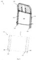
Fig. 1 shows a suspension fabric installed using a wrapped-around method. -
Fig. 2 shows a flowchart illustrating a method for installing a seat suspension. -
Fig. 3 shows a schematic drawing illustrating a seat frame and a seat suspension to be installed onto the seat frame. -
Fig. 4 shows a schematic drawing illustrating a passenger seat having a seat suspension installed onto a seat frame. -
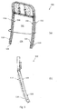
Figs. 5(a) and 5(b) show an isometric view and a side view of a seat frame according to various embodiments. -
Fig. 6 shows a schematic drawing illustrating a seat suspension according to various embodiments. -
Fig. 7 shows a schematic drawing illustrating a passenger seat according to various embodiments. - Various embodiments provide a method for installing a seat suspension onto a seat frame in an easier and space-saving manner. The method of various embodiments not only can be used during manufacturing, but also can be used during maintenance.
- In this context, the word "exemplary" is used herein to mean "serving as an example, instance, or illustration". Any embodiment or design described herein as "exemplary" is not necessarily to be construed as preferred or advantageous over other embodiments or designs.
- In this context, the seat suspension installation method can be performed in various orientations, and thus it should be understood that the terms "side", "top", "bottom", "left", "right", "front", "back", "forward", "rear" etc., when used in the following description are used for convenience and to aid understanding of relative positions or directions, and not intended to limit the seat suspension installation method.
-
Fig. 2 shows aflowchart 200 illustrating a method for installing a seat suspension. The seat frame may include a first side frame member and a second side frame member opposed to and spaced apart from each other. - At 202, a retainer on a first side of the seat suspension is moved in a direction substantially perpendicular to a plane defined by the first and second side frame members for fastening onto a support member on the first side frame member.
- At 204, a retainer on the second side of the seat suspension is moved in the direction substantially perpendicular to the plane defined by the first and second side frame members for fastening onto a support member on the second side frame member. The second side of the seat suspension is opposed to and spaced apart from the first side of the seat suspension.
- The movement of the retainer on the first side of the seat suspension may include moving a plurality of retainers on the first side of the seat suspension in the direction substantially perpendicular to the plane defined by the first and second side frame members for fastening onto a plurality of support members on the first side frame member. The first side frame member may include a plurality of portions at an angle with each other, and the plurality of support members are respectively located on the plurality of portions of the first side frame member. The first side frame member may include a plurality of straight portions at an angle with each other, and the plurality of support members are respectively located on the plurality of portions of the first side frame member. The first side frame member may be of a curved shape, and the plurality of support members may be located corresponding to the curved shape of the first side frame member.
- The movement of the retainer on the second side of the seat suspension may include moving a plurality of retainers on the second side of the seat suspension in the direction substantially perpendicular to the plane defined by the first and second side frame members for fastening onto a plurality of support members on the second side frame member. The second side frame member may include a plurality of portions at an angle with each other, and the plurality of support members are respectively located on the plurality of portions of the second side frame member. The second side frame member may include a plurality of straight portions at an angle with each other, and the plurality of support members are respectively located on the plurality of portions of the second side frame member. The second side frame member may be of a curved shape, and the plurality of support members may be located corresponding to the curved shape of the second side frame member.
- The installation method may include stretching the seat suspension from the first side frame member towards the second side frame member. The seat suspension may be stretched towards the second side frame member after the first side of the seat suspension is installed on the first side frame member, so as to install the second side of the seat suspension onto the second side frame member.
-
Fig. 3 shows aschematic drawing 300 illustrating a seat frame and a seat suspension to be installed onto the seat frame. -
Fig. 3 shows aseat suspension 310 and aseat frame 320. Theseat suspension 310 may be a suspension fabric which is tailored to match seat back geometry and contour. Theseat suspension 310 may also be a seat suspension membrane or sheet made of any suitable material. - A
first side 302 and asecond side 304 of theseat suspension 310 are opposed to and spaced apart from each other. Thefirst side 302 and thesecond side 304 are illustrated as the right side and the left side of the seat suspension, when the seat suspension is oriented upright in its installed state. It is understood that thefirst side 302 and thesecond side 304 may also be the top side and the bottom side of the seat suspension in its upright orientation. - A
retainer 306 may be provided on thefirst side 302, and aretainer 308 may be provided on thesecond side 304. Theretainers first side 302 and thesecond side 304, e.g. using the sewn threads as illustrated inFig. 3 . - Each of the
retainers first side 302 or thesecond side 304 of theseat suspension 310. - The
retainers shaped retainers Fig. 3 having an elongated body with a J-shaped cross-section. - The
retainers retainers first side 302 and thesecond side 304 of theseat suspension 310, respectively. Theretainers first side 302 and thesecond side 304 using other suitable means, such as heat staking or integrally forming or molding theretainers seat suspension 310. - In
Fig. 3 , theseat frame 320 is a seat back frame. - The
seat frame 320 includes a firstside frame member 322 and a secondside frame member 324 opposed to and spaced apart from each other. The firstside frame member 322 and the secondside frame member 324 are illustrated as the right side frame member and the left side frame member of theseat frame 320 in its upright orientation. It is understood that the firstside frame member 322 and the secondside frame member 324 may also be the top side frame member and the bottom side frame member of the seat frame for theseat suspension 310 to be installed in such a manner. - A
support member 326 may be located on the firstside frame member 322, and asupport member 328 may be located on the secondside frame member 324. Thesupport members side frame members support members retainers support members plane 332 defined by the first and secondside frame members support members plane 332 of theseat frame 320 and extend backwardly. Thesupport members seat suspension 310, with or without passenger load. - In
Fig. 3 , theseat suspension 310 is installed onto the front side of theseat frame 320 in a rear-facing direction. It is understood that theseat suspension 310 may also be installed onto the back side of the seat frame in a forward-facing direction in other embodiments. - The
retainer 306 on thefirst side 302 of theseat suspension 310 is moved in thedirection 330 substantially perpendicular to theplane 332 defined by the first and secondside frame members support member 326 on the firstside frame member 322. - After the
retainer 306 on thefirst side 302 of theseat suspension 310 is fastened onto thesupport member 326, theseat suspension 310 may be stretched towards the secondside frame member 324 so that theretainer 308 on thesecond side 304 of theseat suspension 310 is sufficiently close to thesupport member 328 on the secondside frame member 324. Theseat suspension 310 may be stretched using a loop design and a rod, as will be described in more detail below. - The
retainer 308 on thesecond side 304 of theseat suspension 310 is moved in thedirection 330 substantially perpendicular to theplane 332 so as to be fastened onto thesupport member 328 on the secondside frame member 324. In this manner, theseat suspension 310 is installed onto theseat frame 320. -
Fig. 4 shows a schematic drawing illustrating apassenger seat 400 having a seat suspension installed onto a seat frame. - The
passenger seat 400 may include theseat suspension 310 and theseat frame 320 illustrated inFig. 3 in an installed state, wherein thesecond side 304 of theseat suspension 310 installed onto the secondside frame member 324 are shown. - As shown in
Fig. 4 , thesupport member 328 may protrude substantially perpendicularly from theplane 332 defined by the first and second side frame members of theseat frame 320. For example, thesupport member 328 is shown to protrude outward and backward from the secondseat frame member 324. - The
retainer 308 is fastened or latched onto thesupport member 328 on the secondside frame member 324 in thedirection 330 substantially perpendicular to theplane 332 defined by the first and second side frames of theseat frame 320. Theretainer 308 installed in such a manner may be received on the mounting provision on the seat frame, e.g. on thesupport member 328 protruding substantially perpendicularly from theplane 332 as shown inFig. 4 . - In
Fig. 4 , theretainer 308 may include a pair of apposing edges connected by a connecting edge, wherein theretainer 308 is fastened to thesupport member 328 such that the pair of apposing edges extends in thedirection 330 substantially perpendicular to theplane 332 defined by the first and second side frame members. - Although the
retainers - The integration of the seat suspension and the seat frame is realized using retainers and support members with rear-facing engagement. This may ensure that the seat suspension conforms to the shape and contour of the seat back frame, and therefore the intent of creating comfortable sitting position at the interface to passenger is retained throughout the servicing operation after the seats are installed in aircraft. By moving the retainers in the direction substantially perpendicular to the plane defined by the side frame members and fastening the retainers thereby, seat suspension may be easier to be installed during maintenance, in which situation there may be limited space at the side of an aircraft seat, e.g. for an aircraft seat next to the window. Compared to clip-on designs in which the clips/retainers move sideways, the perpendicular movement of the retainers is advantageous in that less space is needed on the sides of the seat frame. The retainers can be flat with a small thickness and yet have a good strength (e.g., in J shape). Whereas for clip-on designs in which clips/retainers move in from the side of the seat frame, the clips/retainers have to protrude the side before clip-on, requiring more space on the sides of the seat frame and requiring thick clips/retainers to clip onto the side of the seat frame. Further, compared to the clip-on designs in which clips/retainers move in from the side of the seat frame, the installation method is advantageous in that fastening of retainers may be more secure, since the retainers fastened in the manner are less likely to dislodge during use.
- Compared to the wrapped-around installation, the method install the seat suspension on either the front side or the back side of the seat frame and also provide additional usable space between the seat frame that may be used for seatback amenity or stowage. The seat suspension is installed from the front side of the seat frame, additional space at the backside of the seat frame is available and may be used for seatback amenity or stowage.
- The use of retainers may ensure that the stretch load is evenly distributed along the two longitudinal sides of the seat back frame. This eliminates the existing requirement of locally reinforcing the seat back frame where the suspension fabric is connected. The thread sew lines, connecting the seat suspension and retainers, are designed for similar consideration. The seat suspension installation method and the passenger seat, an even distribution of stretch load onto the retainers may be achieved. This helps to increase the fatigue life of the seat back assembly which is constantly subjected to human seating loads and aircraft vibrations.
- Depending on the design and contour of the seat frame, the seat suspension may be adapted accordingly as described in more detail below.
-
Figs. 5(a) and 5(b) respectively show an isometric view and a side view of aseat frame 500 according to various embodiments. - Similar to the
seat frame 320 ofFig. 3 , theseat frame 500 includes a first side frame member and a second side frame member opposed to and spaced apart from the first side frame member. - The first side frame member of the
seat frame 500 includes a plurality of portions at an angle with each other. In the exemplary embodiments shown inFig. 5 , the first side frame member includes anupper portion 502 and alower portion 504 at an angle with theupper portion 502. The second side frame member includes anupper portion 506 and alower portion 508 at an angle with theupper portion 506. Theupper portions upper plane 532. Thelower portions lower plane 534. Thelower plane 534 is inclined forward with respect to theupper plane 532 in an exemplary embodiment. - According to the above exemplary embodiments, the
seat frame 500 may be a two-planed seat frame. Theupper plane 532 runs vertically, e.g., to support human spinal in an upright position. Thelower plane 534 is inclined forward, e.g., to seamlessly integrate with the lumbar support. The change of angle from thelower plane 534 to theupper plane 532 may be designed or configured based on the anthropometry data to achieve comfortable sitting position for passengers. The conformity may reduce uneven pressure distribution on the erector spinal and oblique muscles seen in the single plane seat frame design. - Corresponding to the first and second side frame members, an
upper support member 512 and alower support member 514 may be respectively located on theupper portion 502 and thelower portion 504 of the first side frame member, and anupper support member 516 and alower support member 518 may be respectively located on theupper portion 506 and thelower portion 508 of the second side frame member. - In exemplary embodiments, the
upper support members lower support members upper support members lower support members seat frame 500. - Although the exemplary embodiments above describes a two-planed seat frame, it is understood that various embodiments may be applied to a multiple-planed seat frame wherein more than two portions may be included in each of the first and second side frame members, or may be applied to a curved seat frame wherein a plurality of curved portions may be included in each of the first and second side frame members. The number of support members and the curvature of the support members may be adapted according to the curvature of the side frame members.
- Various details of the seat frame and the support members described above with respect to
Figs. 2 to 4 are analogously valid for theseat frame 500, and vice versa. -
Fig. 6 shows a schematic drawing illustrating aseat suspension 600 according to various embodiments. - The
seat suspension 600 may be configured for installation onto theseat frame 500 ofFig. 5 . In various embodiments, theseat frame 500 includes afirst side 602 and asecond side 604 opposed to and spaced apart from each other. - A plurality of retainers may be respectively provided on the
first side 602 and thesecond side 604 of theseat suspension 600. In exemplary embodiments ofFig. 6 , anupper retainer 612 and alower retainer 614 are provided on thefirst side 602, and anupper retainer 616 and alower retainer 618 are provided on thesecond side 604. Thefirst side 602 and thesecond side 604 of theseat suspension 600 may be sewn withthreads 620, e.g. nylon threads, to fix theretainers support members - According to various embodiments, the use of plurality of retainers at each side of the seat suspension may ensure that the stretch load is evenly distributed along the two longitudinal sides of the seat back frame, for example, when the two longitudinal sides of the seat back frame is curved or inclined. According to various embodiments, an even distribution of stretch load onto the retainers may be achieved, thereby increasing the fatigue life of the seat suspension.
- The tension induced in the seat suspension fabric may be varied by controlling the lateral dimensions of the suspension fabric sewn on the retainers. This may allow preference to be exercised on the stiffness of the diaphragm created for ergonomic purposes.
- Various details of the seat suspension and the retainers described above with reference to
Figs. 2 to 4 are analogously valid for theseat suspension 600 and the retainers, and vice versa. - In various embodiments, the seat suspension may further include a
loop member 624 along thesecond side 604 of theseat suspension 600, wherein theloop member 624 is configured to receive a rod therein during installation of theseat suspension 600 onto the seat frame. Theloop member 624 may be formed with excess fabric at thesecond side 604 of theseat suspension 600, and may be sewn with thethreads 620 which are also used for holding the retainers. Theloop member 624 may be formed as an integral part of theseat suspension 600, or as a separate part attached to theseat suspension 600. - In various embodiments, the
loop member 624 may include or may be split into a plurality of loop portions. Theloop member 624 may be split into the plurality of loop portions by forming a cut between adjacent loop portions. In exemplary embodiments ofFig. 6 , a V-shapedcut 626 is formed on theloop member 624 to separate adjacent loop portions, which may allow the option of using a loading rod to grip either each of the loop portion or both loop portions concurrently. - In various embodiments, the
seat suspension 600 may further include aflap 628 at the bottom for integration with a seat pan. Theflap 628 may help to retain the surface tension in the vertical orientation and may create gradually transformation to the seat pan. - In various embodiments, a
loop fastener 630 may be sewn onto the edge of theflap 628, and amating hook fastener 632 may be sewn in the vicinity of theloop fastener 630. The loop and hook fastener, e.g. Velcro, includes theloop fastener 630 and themating hook fastener 632 and is used to hold theflap 628 in place. Theloop fastener 630 and themating hook fastener 632 may be made of fabric, e.g. nylon, polyester, etc. In addition to hook and loop fastener, any other quick releasable fastener, such as buttons, may be included in the seat suspension. - During installation of the
seat suspension 600 onto theseat frame 500, theupper retainer 612 and thelower retainer 614 may be respectively moved in the respective directions substantially perpendicular to theupper plane 532 and thelower plane 534 defined by the first and second side frame members, and respectively latched onto the protrusion of theupper support members 512 and thelower support members 514 on the first side of theseat frame 500. - A loading rod may be inserted or put through the
loop member 624, and is used to stretch theseat suspension 600 across the forward surface of theseat frame 500 from the first side to the second side of theseat frame 500. The direction of the stretching, for example, from left to right or from right to left, depends on the location of theloop member 624. The stretching according to the embodiments may allow the suspension fabric to hug tightly to the side and forward faces of theseat frame 500. - In various embodiments, the rod may be inserted into the plurality of loop portions of the
loop member 624 concurrently, and the seat suspension is stretched from the first side frame member towards the second side frame member by means of the rod. By stretching theseat suspension 600 towards the second side frame member, theretainers second side 604 of theseat suspension 600 may be respectively moved in the directions substantially perpendicular to theupper plane 532 and thelower plane 534 defined by the first and second side frame members. - When the
retainers second side 604 of theseat suspension 600 are close enough to theupper support member 516 and thelower support member 518 of the second side frame member, theretainers upper support member 516 and thelower support member 518, to form thepassenger 700 as shown inFig. 7 . - In various embodiments, the rod may be inserted into one of the plurality of loop portions of the
loop member 624, e.g. the upper loop portion, and theseat suspension 600 is stretched from the first side frame member towards the second side frame member by means of the rod. One of a plurality of retainers on thesecond side 604 of theseat suspension 600, e.g. theupper retainer 616 located corresponding to the upper loop portion with the rod inserted therein, is fastened onto one of a plurality of support members on the second side frame member, e.g. theupper support member 516 located corresponding to theupper retainer 616 which is moved. The rod may be removed and inserted into a subsequent loop portion of the plurality of loop portions, e.g. the lower loop portion, for stretching theseat suspension 600. A subsequent retainer of the plurality of retainers, e.g. thelower retainer 618, on thesecond side 604 of theseat suspension 600 may be fastened onto a subsequent support member of the plurality of support members on the second side frame member, e.g. thelower support member 518. In embodiments wherein more than two loop portions are included in theloop member 624, the above process may be repeated for all loop portions until all of the plurality of retainers on the second side of the seat suspension have been fastened onto the corresponding support members on the second side frame member. -
Fig. 7 shows a schematic drawing illustrating apassenger seat 700 according to various embodiments, wherein theseat suspension 600 ofFig. 6 has been installed on theseat frame 500 ofFig. 5 according to the method of various embodiments above. - The installation method of various embodiments can be provided for aircraft seat production as well as for maintenance of seats already installed on aircrafts. For maintenance, the manual operation of using the loading loop member and the rod preferably allows the technician to ergonomically install the suspension fabric onto its receiving support members on the seat frame. The operation advantageously may only require a single technician to clutch onto both ends of the rod and pull inwards to install comfortably. The loading rod may be bent or contoured similarly to the seat frame for simultaneous gripping of two loading loops in a single motion. For production line runs, mechanized jigs can make use of the loading loop to mount the seat suspension onto the seat frame. Further, the method of various embodiments in which retainers are moved and fastened in a perpendicular direction at the sides of the seat frame allows minimum removal effort, as accessibility is only required at the sides of seat frame (e.g. the left side and the right side of the seat frame) at its installed position. Accordingly, the installation method of various embodiments allows the removal and maintenance of the seat suspension on aircraft without having to remove the seatback frame. For the wrapped-around seat design having a seat suspension without zipper, to service each seat in a 3-seat arrangement, all seatback frames have to be removed from the aircraft in order to access the seat suspension. Compared with the wrapped-around seat design, the installation method of various embodiments requiring accessibility at the side of the seat frame allows the removal of seat suspension while the seatback frame is still in its rigid position on aircraft. This installation method of various embodiments can be advantageously performed by any qualified technicians without additional training, thereby saving both time and cost.
- While the various embodiments above have been described with regard to a seat back frame and the installation of the seat suspension at the front side of the seat back frame, it is understood that the method of various embodiments may also be applied in the installation of the seat suspension at the back side of the seat back frame and may also be applied to a seat pan.
Claims (15)
- A method for installing a seat suspension layer (600) on a seat frame (500) having a first side frame member (502, 504) and a second side frame member (506, 508) opposed to and spaced apart from each other, the method comprising:moving a plurality of retainers (612, 614) on a first side (602) of the seat suspension layer (600) in respective directions substantially perpendicular to respective planes defined by the first (502, 504) and second (506, 508) side frame members for fastening onto a plurality of support members (512, 514) respectively located on a plurality of portions of the first side frame member (502, 504), wherein the respective planes defined by the first (502, 504) and second (506, 508) side frame members are inclined relative to each other; andmoving a plurality of retainers (616, 618) on a second side (604) of the seat suspension layer (600) in the respective directions substantially perpendicular to the respective planes defined by the first (502, 504) and second (506, 508) side frame members for fastening onto a plurality of support members (516, 518) respectively located on a plurality of portions of the second side frame member (506, 508), the second side (604) of the seat suspension layer (600) being opposed to and spaced apart from the first side (602) of the seat suspension layer (600);wherein the respective planes are defined by pairs of a respective portion of the plurality of portions of the first side frame member (502, 504) and a corresponding respective portion of the plurality of portions of the second side frame member (506, 508);wherein each retainer(612, 614) on the first side (602) of the seat suspension layer (600) comprises an elongated body extending along a respective one of the plurality of portions of the first side frame member (502, 504) and each retainer (616, 618) on the second side (604) of the seat suspension layer (600) comprises an elongated body extending along a respective one of the plurality of portions of the second side frame members (506, 508).
- The method according to claim 1, further comprising:inserting a rod into a loop member (624) provided along the second side (604) of the seat suspension layer (600), after the retainers (612, 614) on the first side (602) of the seat suspension layer (600) are fastened onto the support members (512, 514) on the first side frame member (502, 504); andstretching the seat suspension layer (600) from the first side frame member (502, 504) towards the second side frame member (506, 508) by means of the rod.
- The method according to claim 2, further comprising:
fastening the retainers (616, 618) on the second side (604) of the seat suspension layer (600) onto the support members (516, 518) on the second side frame member (506, 508); and removing the rod from the loop member (624). - The method according to claim 2 or 3,
wherein the loop member (624) is split into a plurality of loop portions;
preferably wherein the loop member (624) is split into the plurality of loop portions by forming a cut between adjacent loop portions. - The method according to claim 4, comprising:inserting the rod into the plurality of loop portions concurrently; andstretching the seat suspension layer (600) from the first side frame member (502, 504) towards the second side frame member (506, 508) by means of the rod.
- The method according to claim 4, comprising:inserting the rod into one of the plurality of loop portions;stretching the seat suspension layer (600) from the first side frame member(502, 504) towards the second side frame member (506, 508) by means of the rod;fastening one of the plurality of retainers (616, 618) on the second side (604) of the seat suspension layer (600) onto one of the plurality of support members on the second side frame member (506, 508).
- The method according to claim 6, further comprising:inserting the rod into a subsequent loop portion of the plurality of loop portions; andfastening a subsequent retainer (618) of the plurality of retainers (616, 618) on the second side (604) of the seat suspension layer (600) onto a subsequent support member of the plurality of support members on the second side frame member (506, 508).
- The method according to any one of claims 2 to 7,
wherein the loop member (624) is sewn along the second side (604) of the seat suspension layer (600). - The method according to any one of claims 1 to 8,
wherein the retainer (612, 614, 616, 618) comprises a pair of apposing edges connected by a connecting edge,
wherein the retainer (612, 614, 616, 618) is fastened to the support member such that the pair of apposing edges extends in the direction substantially perpendicular to the plane defined by the first (502, 504) and second (506. 508) side frame members. - The method according to any one of claims 1 to 9,
wherein the retainers (612, 614, 616, 618) are made of plastic, metal, composite, or a material having sufficient strength for the retainers (612, 614, 616, 618) to hold the seat suspension layer (600); and/or
wherein the support member is arranged to protrude substantially perpendicularly from the respective plane defined by the first (502, 504) and second (506. 508) side frame members; and/or
wherein the seat frame (500) is a seat back frame or a seat pan frame; and/or
wherein the seat suspension layer (600) comprises a seat suspension fabric. - A passenger seat, comprising
a seat frame (500) having a first side frame member (502, 504) and a second side frame member (506, 508) opposed to and spaced apart from each other, wherein the first side frame member (502, 504) comprises a plurality of portions and the second side frame member (506, 508) comprises a plurality of portions, wherein respective planes are defined by pairs of a respective one of the plurality of portions of the first side frame member (502, 504) and a corresponding respective one of the plurality of portions of the second side frame member (506, 508) and wherein the respective planes are inclined relative to each other;
a seat suspension layer (600) installed on the seat frame (500);
wherein a plurality of retainers (612, 614) on a first side (602) of the seat suspension layer (600) are fastened onto a plurality of support members respectively located on the plurality of portions of the first side frame member (502, 504), and a plurality of retainers (616, 618) on a second side (604) of the seat suspension layer (600) are fastened onto a plurality of support members respectively located on the plurality of portions of the second side frame member (506, 508), the second side (604) of the seat suspension layer (600) being opposed to and spaced apart from the first side (602) of the seat suspension layer (600);
wherein each retainer (612, 614, 616, 618) comprises a pair of apposing edges connected by a connecting edge;
wherein each retainer (612, 614, 616, 618) is fastened to one of the support members such that the pair of apposing edges extends in a direction substantially perpendicular to the respective planes; and
wherein each retainer (612, 614) on the first side (602) of the seat suspension layer (600) comprises an elongated body extending along a respective one of the plurality of portions of the first side frame member (502, 504) and each retainer (616, 618) on the second side (604) of the seat suspension layer (600) comprises an elongated body extending along a respective one of the plurality of portions of the second side frame members (506, 508). - The passenger seat according to claim 11,
wherein the seat suspension layer (600) comprises a loop member (624) along the second side (604) of the seat suspension layer (600), the loop member (624) being configured to receive a rod therein during installation of the seat suspension layer (600) onto the seat frame (500). - The passenger seat according to claim 12,
wherein the loop member (624) is split into a plurality of loop portions;
preferably wherein the loop member (624) is split into the plurality of loop portions by forming a cut between adjacent loop portions. - The passenger seat according to claim 12 or 13,
wherein the loop member (624) is sewn along the second side (604) of the seat suspension layer (600). - The passenger seat according to any one of claims 11 to 14,
wherein the retainers (612, 614, 616, 618) are made of plastic, metal, composite, or a material having sufficient strength for the retainers (612, 614, 616, 618) to hold the seat suspension layer (600); and/or
wherein the support member is arranged to protrude substantially perpendicularly from the respective plane defined by the first (502, 504) and second (506, 508) side frame members; and/or
wherein the seat frame (500) is a seat back frame or a seat pan frame; and/or
wherein the seat suspension layer (600) comprises a seat suspension fabric.
Applications Claiming Priority (1)
| Application Number | Priority Date | Filing Date | Title |
|---|---|---|---|
| PCT/SG2014/000630 WO2016108752A1 (en) | 2014-12-31 | 2014-12-31 | Seat suspension installation method and passenger seat |
Publications (2)
| Publication Number | Publication Date |
|---|---|
| EP3240727A1 EP3240727A1 (en) | 2017-11-08 |
| EP3240727B1 true EP3240727B1 (en) | 2020-11-25 |
Family
ID=52302291
Family Applications (1)
| Application Number | Title | Priority Date | Filing Date |
|---|---|---|---|
| EP14824947.7A Active EP3240727B1 (en) | 2014-12-31 | 2014-12-31 | Seat suspension installation method and passenger seat |
Country Status (6)
| Country | Link |
|---|---|
| US (1) | US10407174B2 (en) |
| EP (1) | EP3240727B1 (en) |
| JP (1) | JP6339296B2 (en) |
| CN (1) | CN107207094B (en) |
| SG (1) | SG11201703278WA (en) |
| WO (1) | WO2016108752A1 (en) |
Families Citing this family (3)
| Publication number | Priority date | Publication date | Assignee | Title |
|---|---|---|---|---|
| DE102020106035A1 (en) * | 2020-03-05 | 2021-09-09 | Zim Flugsitz Gmbh | Passenger seat with a connecting device and row of seats |
| US11396377B1 (en) * | 2021-05-05 | 2022-07-26 | B/E Aerospace, Inc. | Aircraft seatback cover attachment system |
| DE102022125858B4 (en) * | 2022-10-06 | 2025-01-23 | Grammer Aktiengesellschaft | Vehicle seat with backrest made of frame element and knitted fabric, manufacturing process therefor and interior fittings of a means of transport |
Family Cites Families (34)
| Publication number | Priority date | Publication date | Assignee | Title |
|---|---|---|---|---|
| JPS6019633Y2 (en) * | 1983-03-31 | 1985-06-13 | トヨタ車体株式会社 | seat cover |
| US4790496A (en) | 1987-07-31 | 1988-12-13 | The Jepson Burns Corporation | Aircraft seat with flexible lumbar panel |
| US4842257A (en) | 1987-11-13 | 1989-06-27 | General Motors Corporation | Vehicle seat suspension component and its method of manufacture |
| US4869554A (en) | 1988-05-17 | 1989-09-26 | General Motors Corporation | Elastomeric woven mat seat suspension |
| US5092654A (en) | 1989-03-30 | 1992-03-03 | Aisin Seiki Kabushiki Kaisha | Seatback spring device |
| US5013089A (en) | 1989-09-15 | 1991-05-07 | General Motors Corporation | Thin profile integrated suspension and seat trim cover |
| US5441331A (en) | 1990-04-19 | 1995-08-15 | Concept Seating, Inc. | Seating assembly |
| US5088747A (en) | 1990-09-12 | 1992-02-18 | International Marketing And Design Seating System, Inc. | Wheelchair seating system |
| DE4224063C2 (en) | 1991-07-23 | 1996-12-19 | Toyota Motor Co Ltd | Vehicle seat |
| US5716096A (en) * | 1993-09-20 | 1998-02-10 | Lear Corporation | Drawstring seat cover for attachment to a seat |
| US5439271A (en) | 1993-11-08 | 1995-08-08 | Hoover Universal, Inc. | Vehicle seat with extruded frame members |
| IL109446A (en) | 1994-04-26 | 1999-09-22 | Israel Aircraft Ind Ltd | Vehicle seat |
| US5735578A (en) * | 1995-03-27 | 1998-04-07 | Burns Aerospace Corporation | Quick replacement seat bottom diaphragm |
| IT236832Y1 (en) * | 1995-04-21 | 2000-08-17 | Giuseppe Seroldi | SEAT PLAN FOR ARMCHAIRS SOFAS CHAIRS OR SIMILAR WITH DEVICES FOR FASTENING THE BELTS THAT USE THE TENSION |
| US5560683A (en) | 1995-05-05 | 1996-10-01 | Burns Aerospace Corporation | Replacable seat back diaphragm |
| US6231125B1 (en) | 1997-12-26 | 2001-05-15 | Ts Tech Co., Ltd. | Seat with resilient sheet-formed seat cushion |
| GB9824704D0 (en) | 1998-11-12 | 1999-01-06 | Mgr Foamtex Ltd | Aircraft seats |
| US6983997B2 (en) | 2001-06-29 | 2006-01-10 | Haworth, Inc. | Chair having a suspension seat assembly |
| FR2828455B1 (en) * | 2001-08-09 | 2003-10-31 | Faurecia Sieges Automobile | VEHICLE SEAT AND PROTECTIVE PLUG, IN PARTICULAR FOR FITTING SUCH A SEAT |
| US6722742B2 (en) | 2001-09-05 | 2004-04-20 | Johnson Controls Technology Company | Suspension anchoring system for a seat |
| US7226130B2 (en) * | 2002-09-12 | 2007-06-05 | Steelcase Development Corporation | Seating with comfort surface |
| JP4081347B2 (en) | 2002-10-28 | 2008-04-23 | 株式会社デルタツーリング | Seat structure |
| US6802568B1 (en) | 2003-04-28 | 2004-10-12 | Be Aerospace, Inc. | Segmented beam aircraft passenger seat |
| US7523988B1 (en) | 2003-08-25 | 2009-04-28 | Milsco Manufacturing Company, A Unit Of Jason Incorporated | Seat, suspension, bolster and shell |
| CA2510843A1 (en) | 2005-06-22 | 2006-12-22 | Multina Inc. | Seat framework for bus |
| CA2540908A1 (en) * | 2005-06-22 | 2006-12-22 | Multina Inc. | Modular seat assembly and method of installation thereof |
| DE102006013231B4 (en) * | 2006-03-22 | 2010-08-05 | Lear Corporation, Southfield | Vehicle seat side air bag mount |
| US8465007B2 (en) * | 2006-03-22 | 2013-06-18 | Illinois Tool Works Inc. | Load bearing assembly with elastomeric edge |
| JP2009112698A (en) * | 2007-11-09 | 2009-05-28 | Kanto Auto Works Ltd | Attachment structure of seat cover |
| EP2293980B1 (en) | 2008-07-08 | 2016-03-23 | BE Aerospace, Inc. | Articulating passenger seat |
| FR2940029B1 (en) * | 2008-12-18 | 2011-02-25 | Comatel Casuel | SEAT BACKGROUND ELEMENT FOR SEAT |
| US10342352B2 (en) * | 2009-12-31 | 2019-07-09 | Illinois Tool Works Inc. | Load bearing support surface |
| JP2012125505A (en) * | 2010-12-17 | 2012-07-05 | Tachi S Co Ltd | Fixing structure of end of trim cover of vehicle seat |
| EP3416525B1 (en) * | 2016-03-31 | 2023-03-01 | Franklin Products, Inc. | Seating suspension diaphragm having integrated slide-in attachment means |
-
2014
- 2014-12-31 EP EP14824947.7A patent/EP3240727B1/en active Active
- 2014-12-31 WO PCT/SG2014/000630 patent/WO2016108752A1/en not_active Ceased
- 2014-12-31 CN CN201480084418.3A patent/CN107207094B/en active Active
- 2014-12-31 US US15/540,548 patent/US10407174B2/en active Active
- 2014-12-31 SG SG11201703278WA patent/SG11201703278WA/en unknown
- 2014-12-31 JP JP2017534838A patent/JP6339296B2/en active Active
Non-Patent Citations (1)
| Title |
|---|
| None * |
Also Published As
| Publication number | Publication date |
|---|---|
| EP3240727A1 (en) | 2017-11-08 |
| US10407174B2 (en) | 2019-09-10 |
| JP2018505807A (en) | 2018-03-01 |
| CN107207094A (en) | 2017-09-26 |
| US20180002022A1 (en) | 2018-01-04 |
| JP6339296B2 (en) | 2018-06-06 |
| CN107207094B (en) | 2019-08-23 |
| SG11201703278WA (en) | 2017-05-30 |
| WO2016108752A1 (en) | 2016-07-07 |
Similar Documents
| Publication | Publication Date | Title |
|---|---|---|
| EP2991898B1 (en) | Aircraft seat back assembly | |
| EP2828156B1 (en) | Seat cushion with integrated seat frame attachment structure | |
| EP2825459B1 (en) | Integral molded seat back for composite seat frame and method | |
| US7871039B2 (en) | Modular passenger seat for an aircraft | |
| CN111824428B (en) | Seat disc diaphragm | |
| US9669742B1 (en) | Car seat cover system and method | |
| EP3473544B1 (en) | Lightweight vehicle passenger seat assemblies | |
| US5735578A (en) | Quick replacement seat bottom diaphragm | |
| EP3446978B1 (en) | Contoured stowable seat | |
| CN108372817A (en) | Seat-assembly with bolster sub-component | |
| US10407174B2 (en) | Seat suspension installation method and passenger seat | |
| EP3362358B1 (en) | Passenger seat including a net backrest | |
| US10118704B2 (en) | Hybrid seat pan and diaphragm | |
| US7588297B1 (en) | Shaped fabric chair diaphragm and method of forming same | |
| EP4245663B1 (en) | Composite seat bottom diaphragm | |
| JP2024015195A (en) | vehicle seat | |
| US10358064B2 (en) | Headrest cover | |
| JP7397301B2 (en) | vehicle seat | |
| CN108340818B (en) | Comfortable bracket for chair back | |
| WO2015155688A1 (en) | Lightweight seat | |
| JP2019081545A (en) | Vehicle seat | |
| WO2010033965A1 (en) | Automotive seat back structure |
Legal Events
| Date | Code | Title | Description |
|---|---|---|---|
| STAA | Information on the status of an ep patent application or granted ep patent |
Free format text: STATUS: THE INTERNATIONAL PUBLICATION HAS BEEN MADE |
|
| PUAI | Public reference made under article 153(3) epc to a published international application that has entered the european phase |
Free format text: ORIGINAL CODE: 0009012 |
|
| STAA | Information on the status of an ep patent application or granted ep patent |
Free format text: STATUS: REQUEST FOR EXAMINATION WAS MADE |
|
| 17P | Request for examination filed |
Effective date: 20170425 |
|
| AK | Designated contracting states |
Kind code of ref document: A1 Designated state(s): AL AT BE BG CH CY CZ DE DK EE ES FI FR GB GR HR HU IE IS IT LI LT LU LV MC MK MT NL NO PL PT RO RS SE SI SK SM TR |
|
| AX | Request for extension of the european patent |
Extension state: BA ME |
|
| DAX | Request for extension of the european patent (deleted) | ||
| RAP1 | Party data changed (applicant data changed or rights of an application transferred) |
Owner name: ST ENGINEERING AEROSPACE LTD. |
|
| STAA | Information on the status of an ep patent application or granted ep patent |
Free format text: STATUS: EXAMINATION IS IN PROGRESS |
|
| 17Q | First examination report despatched |
Effective date: 20190128 |
|
| GRAP | Despatch of communication of intention to grant a patent |
Free format text: ORIGINAL CODE: EPIDOSNIGR1 |
|
| STAA | Information on the status of an ep patent application or granted ep patent |
Free format text: STATUS: GRANT OF PATENT IS INTENDED |
|
| INTG | Intention to grant announced |
Effective date: 20200625 |
|
| GRAS | Grant fee paid |
Free format text: ORIGINAL CODE: EPIDOSNIGR3 |
|
| GRAA | (expected) grant |
Free format text: ORIGINAL CODE: 0009210 |
|
| STAA | Information on the status of an ep patent application or granted ep patent |
Free format text: STATUS: THE PATENT HAS BEEN GRANTED |
|
| AK | Designated contracting states |
Kind code of ref document: B1 Designated state(s): AL AT BE BG CH CY CZ DE DK EE ES FI FR GB GR HR HU IE IS IT LI LT LU LV MC MK MT NL NO PL PT RO RS SE SI SK SM TR |
|
| REG | Reference to a national code |
Ref country code: GB Ref legal event code: FG4D |
|
| REG | Reference to a national code |
Ref country code: CH Ref legal event code: EP |
|
| REG | Reference to a national code |
Ref country code: AT Ref legal event code: REF Ref document number: 1338007 Country of ref document: AT Kind code of ref document: T Effective date: 20201215 |
|
| REG | Reference to a national code |
Ref country code: DE Ref legal event code: R096 Ref document number: 602014072753 Country of ref document: DE |
|
| REG | Reference to a national code |
Ref country code: IE Ref legal event code: FG4D |
|
| REG | Reference to a national code |
Ref country code: AT Ref legal event code: MK05 Ref document number: 1338007 Country of ref document: AT Kind code of ref document: T Effective date: 20201125 |
|
| REG | Reference to a national code |
Ref country code: NL Ref legal event code: MP Effective date: 20201125 |
|
| PG25 | Lapsed in a contracting state [announced via postgrant information from national office to epo] |
Ref country code: GR Free format text: LAPSE BECAUSE OF FAILURE TO SUBMIT A TRANSLATION OF THE DESCRIPTION OR TO PAY THE FEE WITHIN THE PRESCRIBED TIME-LIMIT Effective date: 20210226 Ref country code: PT Free format text: LAPSE BECAUSE OF FAILURE TO SUBMIT A TRANSLATION OF THE DESCRIPTION OR TO PAY THE FEE WITHIN THE PRESCRIBED TIME-LIMIT Effective date: 20210325 Ref country code: NO Free format text: LAPSE BECAUSE OF FAILURE TO SUBMIT A TRANSLATION OF THE DESCRIPTION OR TO PAY THE FEE WITHIN THE PRESCRIBED TIME-LIMIT Effective date: 20210225 Ref country code: FI Free format text: LAPSE BECAUSE OF FAILURE TO SUBMIT A TRANSLATION OF THE DESCRIPTION OR TO PAY THE FEE WITHIN THE PRESCRIBED TIME-LIMIT Effective date: 20201125 Ref country code: RS Free format text: LAPSE BECAUSE OF FAILURE TO SUBMIT A TRANSLATION OF THE DESCRIPTION OR TO PAY THE FEE WITHIN THE PRESCRIBED TIME-LIMIT Effective date: 20201125 |
|
| PG25 | Lapsed in a contracting state [announced via postgrant information from national office to epo] |
Ref country code: AT Free format text: LAPSE BECAUSE OF FAILURE TO SUBMIT A TRANSLATION OF THE DESCRIPTION OR TO PAY THE FEE WITHIN THE PRESCRIBED TIME-LIMIT Effective date: 20201125 Ref country code: BG Free format text: LAPSE BECAUSE OF FAILURE TO SUBMIT A TRANSLATION OF THE DESCRIPTION OR TO PAY THE FEE WITHIN THE PRESCRIBED TIME-LIMIT Effective date: 20210225 Ref country code: SE Free format text: LAPSE BECAUSE OF FAILURE TO SUBMIT A TRANSLATION OF THE DESCRIPTION OR TO PAY THE FEE WITHIN THE PRESCRIBED TIME-LIMIT Effective date: 20201125 Ref country code: IS Free format text: LAPSE BECAUSE OF FAILURE TO SUBMIT A TRANSLATION OF THE DESCRIPTION OR TO PAY THE FEE WITHIN THE PRESCRIBED TIME-LIMIT Effective date: 20210325 Ref country code: PL Free format text: LAPSE BECAUSE OF FAILURE TO SUBMIT A TRANSLATION OF THE DESCRIPTION OR TO PAY THE FEE WITHIN THE PRESCRIBED TIME-LIMIT Effective date: 20201125 Ref country code: LV Free format text: LAPSE BECAUSE OF FAILURE TO SUBMIT A TRANSLATION OF THE DESCRIPTION OR TO PAY THE FEE WITHIN THE PRESCRIBED TIME-LIMIT Effective date: 20201125 |
|
| REG | Reference to a national code |
Ref country code: LT Ref legal event code: MG9D |
|
| PG25 | Lapsed in a contracting state [announced via postgrant information from national office to epo] |
Ref country code: HR Free format text: LAPSE BECAUSE OF FAILURE TO SUBMIT A TRANSLATION OF THE DESCRIPTION OR TO PAY THE FEE WITHIN THE PRESCRIBED TIME-LIMIT Effective date: 20201125 |
|
| REG | Reference to a national code |
Ref country code: DE Ref legal event code: R119 Ref document number: 602014072753 Country of ref document: DE |
|
| PG25 | Lapsed in a contracting state [announced via postgrant information from national office to epo] |
Ref country code: LT Free format text: LAPSE BECAUSE OF FAILURE TO SUBMIT A TRANSLATION OF THE DESCRIPTION OR TO PAY THE FEE WITHIN THE PRESCRIBED TIME-LIMIT Effective date: 20201125 Ref country code: SK Free format text: LAPSE BECAUSE OF FAILURE TO SUBMIT A TRANSLATION OF THE DESCRIPTION OR TO PAY THE FEE WITHIN THE PRESCRIBED TIME-LIMIT Effective date: 20201125 Ref country code: RO Free format text: LAPSE BECAUSE OF FAILURE TO SUBMIT A TRANSLATION OF THE DESCRIPTION OR TO PAY THE FEE WITHIN THE PRESCRIBED TIME-LIMIT Effective date: 20201125 Ref country code: SM Free format text: LAPSE BECAUSE OF FAILURE TO SUBMIT A TRANSLATION OF THE DESCRIPTION OR TO PAY THE FEE WITHIN THE PRESCRIBED TIME-LIMIT Effective date: 20201125 Ref country code: EE Free format text: LAPSE BECAUSE OF FAILURE TO SUBMIT A TRANSLATION OF THE DESCRIPTION OR TO PAY THE FEE WITHIN THE PRESCRIBED TIME-LIMIT Effective date: 20201125 Ref country code: CZ Free format text: LAPSE BECAUSE OF FAILURE TO SUBMIT A TRANSLATION OF THE DESCRIPTION OR TO PAY THE FEE WITHIN THE PRESCRIBED TIME-LIMIT Effective date: 20201125 |
|
| REG | Reference to a national code |
Ref country code: CH Ref legal event code: PL |
|
| PG25 | Lapsed in a contracting state [announced via postgrant information from national office to epo] |
Ref country code: DK Free format text: LAPSE BECAUSE OF FAILURE TO SUBMIT A TRANSLATION OF THE DESCRIPTION OR TO PAY THE FEE WITHIN THE PRESCRIBED TIME-LIMIT Effective date: 20201125 Ref country code: MC Free format text: LAPSE BECAUSE OF FAILURE TO SUBMIT A TRANSLATION OF THE DESCRIPTION OR TO PAY THE FEE WITHIN THE PRESCRIBED TIME-LIMIT Effective date: 20201125 |
|
| REG | Reference to a national code |
Ref country code: BE Ref legal event code: MM Effective date: 20201231 |
|
| PLBE | No opposition filed within time limit |
Free format text: ORIGINAL CODE: 0009261 |
|
| STAA | Information on the status of an ep patent application or granted ep patent |
Free format text: STATUS: NO OPPOSITION FILED WITHIN TIME LIMIT |
|
| GBPC | Gb: european patent ceased through non-payment of renewal fee |
Effective date: 20210225 |
|
| PG25 | Lapsed in a contracting state [announced via postgrant information from national office to epo] |
Ref country code: LU Free format text: LAPSE BECAUSE OF NON-PAYMENT OF DUE FEES Effective date: 20201231 Ref country code: NL Free format text: LAPSE BECAUSE OF FAILURE TO SUBMIT A TRANSLATION OF THE DESCRIPTION OR TO PAY THE FEE WITHIN THE PRESCRIBED TIME-LIMIT Effective date: 20201125 Ref country code: FR Free format text: LAPSE BECAUSE OF NON-PAYMENT OF DUE FEES Effective date: 20210125 Ref country code: AL Free format text: LAPSE BECAUSE OF FAILURE TO SUBMIT A TRANSLATION OF THE DESCRIPTION OR TO PAY THE FEE WITHIN THE PRESCRIBED TIME-LIMIT Effective date: 20201125 Ref country code: IE Free format text: LAPSE BECAUSE OF NON-PAYMENT OF DUE FEES Effective date: 20201231 Ref country code: IT Free format text: LAPSE BECAUSE OF FAILURE TO SUBMIT A TRANSLATION OF THE DESCRIPTION OR TO PAY THE FEE WITHIN THE PRESCRIBED TIME-LIMIT Effective date: 20201125 |
|
| 26N | No opposition filed |
Effective date: 20210826 |
|
| PG25 | Lapsed in a contracting state [announced via postgrant information from national office to epo] |
Ref country code: LI Free format text: LAPSE BECAUSE OF NON-PAYMENT OF DUE FEES Effective date: 20201231 Ref country code: DE Free format text: LAPSE BECAUSE OF NON-PAYMENT OF DUE FEES Effective date: 20210701 Ref country code: CH Free format text: LAPSE BECAUSE OF NON-PAYMENT OF DUE FEES Effective date: 20201231 Ref country code: SI Free format text: LAPSE BECAUSE OF FAILURE TO SUBMIT A TRANSLATION OF THE DESCRIPTION OR TO PAY THE FEE WITHIN THE PRESCRIBED TIME-LIMIT Effective date: 20201125 |
|
| PG25 | Lapsed in a contracting state [announced via postgrant information from national office to epo] |
Ref country code: GB Free format text: LAPSE BECAUSE OF NON-PAYMENT OF DUE FEES Effective date: 20210225 Ref country code: ES Free format text: LAPSE BECAUSE OF FAILURE TO SUBMIT A TRANSLATION OF THE DESCRIPTION OR TO PAY THE FEE WITHIN THE PRESCRIBED TIME-LIMIT Effective date: 20201125 |
|
| PG25 | Lapsed in a contracting state [announced via postgrant information from national office to epo] |
Ref country code: IS Free format text: LAPSE BECAUSE OF FAILURE TO SUBMIT A TRANSLATION OF THE DESCRIPTION OR TO PAY THE FEE WITHIN THE PRESCRIBED TIME-LIMIT Effective date: 20210325 Ref country code: TR Free format text: LAPSE BECAUSE OF FAILURE TO SUBMIT A TRANSLATION OF THE DESCRIPTION OR TO PAY THE FEE WITHIN THE PRESCRIBED TIME-LIMIT Effective date: 20201125 Ref country code: MT Free format text: LAPSE BECAUSE OF FAILURE TO SUBMIT A TRANSLATION OF THE DESCRIPTION OR TO PAY THE FEE WITHIN THE PRESCRIBED TIME-LIMIT Effective date: 20201125 Ref country code: CY Free format text: LAPSE BECAUSE OF FAILURE TO SUBMIT A TRANSLATION OF THE DESCRIPTION OR TO PAY THE FEE WITHIN THE PRESCRIBED TIME-LIMIT Effective date: 20201125 |
|
| PG25 | Lapsed in a contracting state [announced via postgrant information from national office to epo] |
Ref country code: MK Free format text: LAPSE BECAUSE OF FAILURE TO SUBMIT A TRANSLATION OF THE DESCRIPTION OR TO PAY THE FEE WITHIN THE PRESCRIBED TIME-LIMIT Effective date: 20201125 |
|
| PG25 | Lapsed in a contracting state [announced via postgrant information from national office to epo] |
Ref country code: BE Free format text: LAPSE BECAUSE OF NON-PAYMENT OF DUE FEES Effective date: 20201231 |