EP3240643B1 - Locking sidewall brace for collapsible fluid containment devices - Google Patents
Locking sidewall brace for collapsible fluid containment devices Download PDFInfo
- Publication number
- EP3240643B1 EP3240643B1 EP15826007.5A EP15826007A EP3240643B1 EP 3240643 B1 EP3240643 B1 EP 3240643B1 EP 15826007 A EP15826007 A EP 15826007A EP 3240643 B1 EP3240643 B1 EP 3240643B1
- Authority
- EP
- European Patent Office
- Prior art keywords
- sidewall
- brace
- support arm
- support leg
- base support
- Prior art date
- Legal status (The legal status is an assumption and is not a legal conclusion. Google has not performed a legal analysis and makes no representation as to the accuracy of the status listed.)
- Active
Links
Images





Classifications
-
- F—MECHANICAL ENGINEERING; LIGHTING; HEATING; WEAPONS; BLASTING
- F16—ENGINEERING ELEMENTS AND UNITS; GENERAL MEASURES FOR PRODUCING AND MAINTAINING EFFECTIVE FUNCTIONING OF MACHINES OR INSTALLATIONS; THERMAL INSULATION IN GENERAL
- F16M—FRAMES, CASINGS OR BEDS OF ENGINES, MACHINES OR APPARATUS, NOT SPECIFIC TO ENGINES, MACHINES OR APPARATUS PROVIDED FOR ELSEWHERE; STANDS; SUPPORTS
- F16M11/00—Stands or trestles as supports for apparatus or articles placed thereon ; Stands for scientific apparatus such as gravitational force meters
- F16M11/20—Undercarriages with or without wheels
- F16M11/2007—Undercarriages with or without wheels comprising means allowing pivoting adjustment
- F16M11/2021—Undercarriages with or without wheels comprising means allowing pivoting adjustment around a horizontal axis
-
- B—PERFORMING OPERATIONS; TRANSPORTING
- B08—CLEANING
- B08B—CLEANING IN GENERAL; PREVENTION OF FOULING IN GENERAL
- B08B17/00—Methods preventing fouling
- B08B17/02—Preventing deposition of fouling or of dust
- B08B17/025—Prevention of fouling with liquids by means of devices for containing or collecting said liquids
-
- B—PERFORMING OPERATIONS; TRANSPORTING
- B64—AIRCRAFT; AVIATION; COSMONAUTICS
- B64F—GROUND OR AIRCRAFT-CARRIER-DECK INSTALLATIONS SPECIALLY ADAPTED FOR USE IN CONNECTION WITH AIRCRAFT; DESIGNING, MANUFACTURING, ASSEMBLING, CLEANING, MAINTAINING OR REPAIRING AIRCRAFT, NOT OTHERWISE PROVIDED FOR; HANDLING, TRANSPORTING, TESTING OR INSPECTING AIRCRAFT COMPONENTS, NOT OTHERWISE PROVIDED FOR
- B64F5/00—Designing, manufacturing, assembling, cleaning, maintaining or repairing aircraft, not otherwise provided for; Handling, transporting, testing or inspecting aircraft components, not otherwise provided for
- B64F5/30—Cleaning aircraft
-
- F—MECHANICAL ENGINEERING; LIGHTING; HEATING; WEAPONS; BLASTING
- F16—ENGINEERING ELEMENTS AND UNITS; GENERAL MEASURES FOR PRODUCING AND MAINTAINING EFFECTIVE FUNCTIONING OF MACHINES OR INSTALLATIONS; THERMAL INSULATION IN GENERAL
- F16N—LUBRICATING
- F16N31/00—Means for collecting, retaining, or draining-off lubricant in or on machines or apparatus
- F16N31/006—Drip trays
-
- B—PERFORMING OPERATIONS; TRANSPORTING
- B64—AIRCRAFT; AVIATION; COSMONAUTICS
- B64F—GROUND OR AIRCRAFT-CARRIER-DECK INSTALLATIONS SPECIALLY ADAPTED FOR USE IN CONNECTION WITH AIRCRAFT; DESIGNING, MANUFACTURING, ASSEMBLING, CLEANING, MAINTAINING OR REPAIRING AIRCRAFT, NOT OTHERWISE PROVIDED FOR; HANDLING, TRANSPORTING, TESTING OR INSPECTING AIRCRAFT COMPONENTS, NOT OTHERWISE PROVIDED FOR
- B64F1/00—Ground or aircraft-carrier-deck installations
- B64F1/28—Liquid-handling installations specially adapted for fuelling stationary aircraft
-
- F—MECHANICAL ENGINEERING; LIGHTING; HEATING; WEAPONS; BLASTING
- F16—ENGINEERING ELEMENTS AND UNITS; GENERAL MEASURES FOR PRODUCING AND MAINTAINING EFFECTIVE FUNCTIONING OF MACHINES OR INSTALLATIONS; THERMAL INSULATION IN GENERAL
- F16M—FRAMES, CASINGS OR BEDS OF ENGINES, MACHINES OR APPARATUS, NOT SPECIFIC TO ENGINES, MACHINES OR APPARATUS PROVIDED FOR ELSEWHERE; STANDS; SUPPORTS
- F16M2200/00—Details of stands or supports
- F16M2200/02—Locking means
- F16M2200/021—Locking means for rotational movement
- F16M2200/022—Locking means for rotational movement by friction
Definitions
- the present invention relates to collapsible fluid containment devices, and more particularly relates to locking sidewall support braces for use in fluid containment devices.
- Portable collapsible liquid containment devices are used to prevent hazardous fluids from entering the environment from, for example, spillage of the fluids during loading and unloading of transport vehicles, wash-down of equipment and vehicles, and repair/maintenance of equipment and vehicles.
- one or more sides of the containment device can be lowered and laid flat so that the equipment or vehicle can easily enter the containment area.
- the sidewall(s) are then raised to prevent fluids from escaping. Any spilled fluid or wash-down fluid is retained within the container and can be pumped out for proper disposal.
- the sidewall(s) can be lowered again to remove the equipment or vehicle.
- the container can then be folded or rolled-up for storage and transport.
- Such containment devices are typically made with a flexible barrier material, such as a rubberized fabric, reinforced polyvinyl chloride (PVC), reinforced thermoplastic polyurethane (TPU) and/or a heavy gauge polymer film.
- a flexible barrier material such as a rubberized fabric, reinforced polyvinyl chloride (PVC), reinforced thermoplastic polyurethane (TPU) and/or a heavy gauge polymer film.
- PVC polyvinyl chloride
- TPU thermoplastic polyurethane
- a heavy gauge polymer film a heavy gauge polymer film.
- collapsible sidewall braces may be employed, as exemplified in US Patent Nos. 5,316,175 ; 5,762,233 ; 6,092,686 ; 6,880,720 ; and 8,562,251 and published US Patent Application Nos. 2013/0240538 and 2014/0246441 .
- US Patent Application No. 2013/0240538 discloses a sidewall brace for use in a collapsible
- An aspect of the present invention is to provide portable collapsible fluid containment devices comprising sidewall support braces that rotate from a collapsed generally horizontal position to a raised generally vertical position and lock into place.
- the sidewall braces may be attached to at least one sidewall of the containment device, and when raised support the sidewall in a fluid containment configuration.
- the sidewall braces comprise a base support leg, a sidewall support arm rotatably mounted on the support leg, and a locking tab for holding the sidewall support arm in the generally vertical position.
- An aspect of the present invention is to provide a collapsible fluid containment device comprising a collapsible sidewall, and a plurality of sidewall braces attached to the collapsible sidewall, wherein each sidewall brace comprises a base support leg, and a sidewall support arm pivotably mounted on the base support leg around an axis of rotation, wherein the sidewall support arm comprises a locking tab including a radial projection extending from the locking tab radially from the axis of rotation engageable with an upper surface of the base support leg.
- a sidewall brace for use in a collapsible fluid containment device in accordance with claim 1 is provided.
- Fig. 1 illustrates a fluid containment device 5 in accordance with a preferred embodiment of the present invention.
- the containment device 5 includes a bottom panel 6 and multiple collapsible sidewalls 7.
- the bottom panel 6 and sidewalls 7 may be made of any suitable type of fluid-impermeable material, such as rubberized fabric, reinforced polyvinyl chloride (PVC), reinforced thermoplastic polyurethane (TPU) and/or a heavy gauge polymer film, and the like.
- PVC polyvinyl chloride
- TPU thermoplastic polyurethane
- Each sidewall 7 includes multiple bracket-receiving pockets 8. Each pocket 8 receives a sidewall support arm of a sidewall brace 10, as more fully described below. Similar pockets (not shown) may be provided under the bottom panel 6 to receive base support legs of the sidewall braces 10.
- Figs. 2-9 illustrate a locking sidewall brace 10 in accordance with an embodiment of the present invention.
- the locking sidewall brace 10 includes a base support leg 12 having a first end 14 and a second end 16.
- the base support leg 12 includes a contact surface 13.
- a raised portion 15 of the base support leg 12 is provided near the first end 14 of the base support leg 12.
- the base support leg 12 includes support ribs 17 terminating in stop members 18.
- a hole 19 is provided through the base support leg for receiving a stake (not shown) or other mechanical device for securing the locking sidewall brace 10 to the ground during use.
- the first end 14 of the base support leg 12 and the support ribs 17 form a low-profile ramp having a ramp angle A measured from a horizontal plane.
- the ramp angle A is selected to facilitate the travel of wheeled vehicles over the sidewall brace 10, e.g., when traversing the sidewall 7 upon entering or exiting the containment area of the containment device 5.
- the ramp angle A may typically range from 5° to 45°, for example, from 10° to 30°, or from 15° to 25°. This section is tapered downward and away from the containment area. This allows the wheels of vehicles and equipment entering the containment area when the sidewall is down roll easily over the brace.
- the locking sidewall brace 10 also includes a rotatable sidewall support arm 20 having a first end 22 and a second end 24. A cut-out portion 23 is provided in the sidewall support arm 20 near the first end 22. As shown most clearly in the sectional views of Figs. 7 and 9 , the rotatable sidewall support arm 20 includes an eccentric locking tab 25 near the first end 22. The locking tab 25 includes a notch 26 and a radial projection 27. As more fully described below, when the sidewall support arm 20 is rotated from the substantially horizontal collapsed position shown in Fig. 7 to the substantially vertical raised position shown in Fig.
- the radial projection 27 of the locking tab 25 presses against and moves across the contact surface 13 of the base support leg 12 when the sidewall support arm 20 reaches a pre-determined rotational position.
- the locking tab 25 acts to resist rotation of the sidewall support arm 20 back to its collapsed position.
- the notch 26 in the locking tab 25 provides resiliency and spring action for the radial projection 27 as it moves over the contact surface 13.
- a pivot hole 29 is provided through the sidewall support arm 20 for receiving a pivot pin 30 around which the sidewall support arm 20 rotates in relation to the base support leg 12.
- the stop members 18 of the base support leg 12 contact the first end 22 of the sidewall support arm 20 when it is in the raised position, thereby providing a mechanical stop that prevents the sidewall support arm 20 from rotating beyond the desired extended position.
- Figs. 10-15 illustrate a locking sidewall brace 110 in accordance with another embodiment of the present disclosure. Similar element numbers are used in Figs. 10-15 for common features that are present in the embodiment of Figs. 2-9 .
- Figs. 10 and 11 illustrate the locking sidewall brace 110 with its rotatable sidewall support arm 120 in a collapsed position.
- Figs. 12 and 13 illustrate the locking sidewall brace 110 with the rotatable sidewall support arm 120 in an intermediate position.
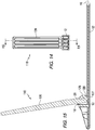
- Figs. 14 and 15 illustrate the locking sidewall brace 110 with the rotatable sidewall support arm 120 in a fully raised position.
- the rotatable support arm 120 includes an eccentric locking tab 125 having a curved contact surface 126 and a radial projection 127.
- the curved contact surface 126 may be circular and is circumferentially spaced from the radial projection 127, as measured around the axis of rotation of the sidewall support arm 120.
- the radial projection 127 contacts the contact surface 13 of the support leg 12 when the support arm 120 is rotated from the raised position to the collapsed position to thereby help hold the support arm 120 in its raised position.
- Figs. 16 and 17 illustrate a locking sidewall brace 210 in accordance with a further embodiment of the present disclosure.
- the locking sidewall brace 210 includes a rotatable sidewall support arm 220, which is shown in an intermediate position in Figs. 16 and 17 between a fully collapsed position and a fully raised position.
- the rotatable sidewall support arm 220 includes an eccentric locking tab 225 with a curved contact surface 226 and a radial projection 227.
- the curved contact surface 226 and radial projection 227 form a cammed configuration in which the radial projection provides a cam surface.
- the cam surface of the radial projection 227 contacts the contact surface 13 of the support leg 12 when the support arm 220 is rotated from the raised position to the collapsed position to thereby help hold the support arm 220 in its raised position.
- the sidewall support arms 20, 120 and 220 of the sidewall braces 10, 110 and 210 offer minimal resistance to rotation from their initial collapsed horizontal positions until the support arms have rotated upward, e.g., to approximately 75° from horizontal. At this point, resistance or torque increases, e.g., for approximately 5° to 15° of rotation, then returns to minimal resistance until the support arms 20, 120, 220 contact the mechanical stops 18.
- the frictional engagement between the locking tabs 25, 125 and 225 and the contact surface 13 of the base support leg 12 occurs at a resistance angle of from 60° to 90° from a horizontal plane, for example, from 70° to 80°.
- the locking tabs may have single or multiple radial projections.
- the radial projections may have a curvilinear profile as shown in the figures, or an angular profile such as a ratchet tooth.
- Projection(s) may also be included on the base support leg 12 to contact the radial projection(s) of the sidewall support arms 20, 120 and 220.
- either the locking tabs 25, 125 and 225, or the contacted surface 13 of the base support leg 12, or both, may flex to provide clearance for the sidewall support arms 20, 120 and 220 to continue rotation.
- Such flexing provides the rotational resistance for the locking mechanism.
- the rotation resistance may be lower than torque exerted by hydrostatic pressure of a contained liquid when it presses against the sidewall 7.
- the rotation resistance may be controlled by the spacing of the sidewall braces 10 from each other, the vertical design height of the containment device, and the specific gravity of the liquid being contained. For example, a minimal level may be about 0.45 Nm (4 pound-inch) in order to resist wind gusts and other forces from unintentionally lowering the sidewall when the containment device is empty of liquid.
- the mechanical stops 18 may be located to prevent the support arms 20, 120 and 220 from rotating past approximately 90° from horizontal.
- the mechanical stops 18 may stop rotation of the sidewall support arms 20, 120 and 220 at a stop angle of from 90° to 120°, or from 100° to 110°, or at about 105°, from horizontal.
- the support arms 20, 120 and 220 are thus trapped or locked in an upright position between the mechanical stops 18 and the high rotation resistance position of the support arms 20, 120 and 220 when their locking tabs 25, 125 and 225 engage the contact surface 13 of the base support leg 12.
- such an upright range may be from 60° to 120° from horizontal, typically between 70° and 110°, or between 75° and 105°, all of which are inclusive of 90°.
- a sufficient amount of torque is applied against the support arms 20, 120 and 220 to overcome the high rotation resistance of the locking tabs 25, 125 and 225.
- the base support leg 12 and the sidewall support arms 20, 120 and 220 may be made of any suitable material, e.g., injection molded from plastic.
- the legs and arms may be made from nylon or filled nylon for strength. Alternately any moldable plastic can be used or they can be cast or machined from metal such as aluminum.
- the support legs and support arms can be made of separate material types.
- the pivot pin 30 is preferably made from a non-oxidizing material such as stainless steel.
- the pivot pin 30 can be a stainless steel shoulder bolt retained by a stainless steel lock nut.
- the pivot pin 30 can be made of plastic and can be molded as an integral section of the either the horizontal support leg or the support arm.
- Each horizontal support leg 12 may be attached to the underside of the containment device floor 6, and each support arm 20, 120, 220 may be attached to the sidewall 7 of the containment device 5.
- the support arms 20, 120 and 220 may be inserted in the pockets 8 attached to the sidewalls 7.
- the base support legs 12 may be inserted in pockets (not shown) under the bottom panel 6.
- the pockets 8 are attached to the exterior side of the sidewall 7.
- pockets may be provided on the interior of the sidewall 7, in which case the sidewall braces 10 may be located inside the sidewall 7 with their sidewall support arms inside the pockets and their base support legs inserted into pockets located above the bottom panel 6.
- each sidewall support arm 20, 120 and 220 can be rotated from a horizontal position to an approximate vertical position as to raise the containment sidewall. To lower the sidewall the support arm is returned to the horizontal position.
- the direction of rotation of the support arms 20, 120 and 220 may be such that it pivots downward toward the interior of the containment device 5 when the sidewall 7 is lowered.
- An advantage of having little or no initial rotational resistance of the support arms 20, 120 and 220 when they are in their collapsed positions is that the hydrostatic pressure of a liquid entering the containment device 5 when the sidewall(s) 7 are lowered is sufficient to self-rise the sidewall(s) 7 to a position above the liquid height. As the height of the fluid level rises in the containment device 5, so does the sidewall height. When the sidewall(s) 7 reach a height corresponding to about 75° of rotation, the hydrostatic pressure of the liquid has increased enough to force the support arms 20, 120 and 220 through the high rotation resistant section and back against the mechanical stop 18 so that the sidewall 7 is in its fully raised and locked position.
- the liquid can easy rotate the sidewall braces 10 and sidewall 7 to a height of about 29.5 cm (11.6 inches) (75° of rotation).
- a liquid having a specific gravity of approximately 0.9 reaches a height of 28 cm (11 inches)
- the hydrostatic pressure will force the sidewall braces 10 and sidewall 7 they are attached to past the high rotation resistant section and toward the mechanical stop 18.
Landscapes
- Engineering & Computer Science (AREA)
- General Engineering & Computer Science (AREA)
- Mechanical Engineering (AREA)
- Manufacturing & Machinery (AREA)
- Transportation (AREA)
- Aviation & Aerospace Engineering (AREA)
- Clamps And Clips (AREA)
- Pivots And Pivotal Connections (AREA)
- Cleaning In General (AREA)
- Vehicle Cleaning, Maintenance, Repair, Refitting, And Outriggers (AREA)
- Supports For Pipes And Cables (AREA)
- Snaps, Bayonet Connections, Set Pins, And Snap Rings (AREA)
- Medical Preparation Storing Or Oral Administration Devices (AREA)
- Tents Or Canopies (AREA)
- Orthopedics, Nursing, And Contraception (AREA)
Description
- The present invention relates to collapsible fluid containment devices, and more particularly relates to locking sidewall support braces for use in fluid containment devices.
- Portable collapsible liquid containment devices are used to prevent hazardous fluids from entering the environment from, for example, spillage of the fluids during loading and unloading of transport vehicles, wash-down of equipment and vehicles, and repair/maintenance of equipment and vehicles. Typically one or more sides of the containment device can be lowered and laid flat so that the equipment or vehicle can easily enter the containment area. Once the equipment or vehicle is inside, the sidewall(s) are then raised to prevent fluids from escaping. Any spilled fluid or wash-down fluid is retained within the container and can be pumped out for proper disposal. After the container is emptied, the sidewall(s) can be lowered again to remove the equipment or vehicle. The container can then be folded or rolled-up for storage and transport.
- Such containment devices are typically made with a flexible barrier material, such as a rubberized fabric, reinforced polyvinyl chloride (PVC), reinforced thermoplastic polyurethane (TPU) and/or a heavy gauge polymer film. During use, the containment device is unfolded/unrolled and the sides extended to a generally vertical position to achieve its fluid retaining capability. To maintain the sidewalls in this generally vertical position, collapsible sidewall braces may be employed, as exemplified in
US Patent Nos. 5,316,175 ;5,762,233 ;6,092,686 ;6,880,720 ; and8,562,251 and publishedUS Patent Application Nos. 2013/0240538 and2014/0246441 .US Patent Application No. 2013/0240538 discloses a sidewall brace for use in a collapsible fluid containment device in accordance with the preamble of claim 1. - An aspect of the present invention is to provide portable collapsible fluid containment devices comprising sidewall support braces that rotate from a collapsed generally horizontal position to a raised generally vertical position and lock into place. The sidewall braces may be attached to at least one sidewall of the containment device, and when raised support the sidewall in a fluid containment configuration. The sidewall braces comprise a base support leg, a sidewall support arm rotatably mounted on the support leg, and a locking tab for holding the sidewall support arm in the generally vertical position.
- An aspect of the present invention is to provide a collapsible fluid containment device comprising a collapsible sidewall, and a plurality of sidewall braces attached to the collapsible sidewall, wherein each sidewall brace comprises a base support leg, and a sidewall support arm pivotably mounted on the base support leg around an axis of rotation, wherein the sidewall support arm comprises a locking tab including a radial projection extending from the locking tab radially from the axis of rotation engageable with an upper surface of the base support leg.
- In accordance with the present invention a sidewall brace for use in a collapsible fluid containment device in accordance with claim 1 is provided.
- These and other aspects of the present invention will be more apparent from the following description.
-
-
Fig. 1 is an isometric view of a fluid containment device including multiple locking sidewall braces in accordance with an embodiment of the present invention. -
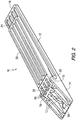
Fig. 2 is an isometric view of a locking sidewall brace in a collapsed position in accordance with an embodiment of the present invention. -
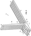
Fig. 3 is an isometric view of a locking sidewall brace in a raised position in accordance with an embodiment of the present invention. -
Fig. 4 is a side view of a locking sidewall brace in a collapsed position in accordance with an embodiment of the present invention. -
Fig. 5 is a side view of a locking sidewall brace in a raised position in accordance with an embodiment of the present invention. -
Fig. 6 is an end view of a collapsed locking sidewall brace in accordance with an embodiment of the present invention. -
Fig. 7 is a sectional view of the locking sidewall brace taken through section 7-7 ofFig. 6 . -
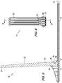
Fig. 8 is an end view of a raised locking sidewall brace in accordance with an embodiment of the present invention. -
Fig. 9 is a sectional view of the locking sidewall brace taken through section 9-9 ofFig. 8 . -
Fig. 10 is an end view of a collapsed locking sidewall brace in accordance with another embodiment of the present disclosure. -
Fig. 11 is a sectional view of the locking sidewall brace taken through section 11-11 ofFig. 10 . -
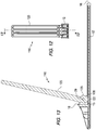
Fig. 12 is an end view of the locking sidewall brace ofFigs. 10 and 11 with its sidewall support arm rotated to an intermediate position. -
Fig. 13 is a sectional view of the locking sidewall brace taken through section 13-13 ofFig. 12 . -
Fig. 14 is an end view of the locking sidewall brace ofFigs. 10-13 in a fully raised position. -
Fig. 15 is a sectional view of the locking sidewall brace taken through section 15-15 ofFig. 14 . -
Fig. 16 is an end view of a locking sidewall brace in an intermediate position between a collapsed position and a fully raised position in accordance with an embodiment of the present diclosure. -
Fig. 17 is a sectional view of the locking sidewall brace taken through section 17-17 ofFig. 16 . -
Fig. 1 illustrates afluid containment device 5 in accordance with a preferred embodiment of the present invention. Thecontainment device 5 includes abottom panel 6 and multiplecollapsible sidewalls 7. Thebottom panel 6 andsidewalls 7 may be made of any suitable type of fluid-impermeable material, such as rubberized fabric, reinforced polyvinyl chloride (PVC), reinforced thermoplastic polyurethane (TPU) and/or a heavy gauge polymer film, and the like. Eachsidewall 7 includes multiple bracket-receivingpockets 8. Eachpocket 8 receives a sidewall support arm of asidewall brace 10, as more fully described below. Similar pockets (not shown) may be provided under thebottom panel 6 to receive base support legs of thesidewall braces 10. -
Figs. 2-9 illustrate alocking sidewall brace 10 in accordance with an embodiment of the present invention. Thelocking sidewall brace 10 includes abase support leg 12 having afirst end 14 and asecond end 16. Thebase support leg 12 includes acontact surface 13. A raisedportion 15 of thebase support leg 12 is provided near thefirst end 14 of thebase support leg 12. Thebase support leg 12 includessupport ribs 17 terminating instop members 18. Ahole 19 is provided through the base support leg for receiving a stake (not shown) or other mechanical device for securing thelocking sidewall brace 10 to the ground during use. - As shown in
Figs. 2 and4 , thefirst end 14 of thebase support leg 12 and thesupport ribs 17 form a low-profile ramp having a ramp angle A measured from a horizontal plane. The ramp angle A is selected to facilitate the travel of wheeled vehicles over thesidewall brace 10, e.g., when traversing thesidewall 7 upon entering or exiting the containment area of thecontainment device 5. The ramp angle A may typically range from 5° to 45°, for example, from 10° to 30°, or from 15° to 25°. This section is tapered downward and away from the containment area. This allows the wheels of vehicles and equipment entering the containment area when the sidewall is down roll easily over the brace. - The
locking sidewall brace 10 also includes a rotatablesidewall support arm 20 having afirst end 22 and asecond end 24. A cut-outportion 23 is provided in thesidewall support arm 20 near thefirst end 22. As shown most clearly in the sectional views ofFigs. 7 and9 , the rotatablesidewall support arm 20 includes aneccentric locking tab 25 near thefirst end 22. Thelocking tab 25 includes anotch 26 and aradial projection 27. As more fully described below, when thesidewall support arm 20 is rotated from the substantially horizontal collapsed position shown inFig. 7 to the substantially vertical raised position shown inFig. 9 , theradial projection 27 of thelocking tab 25 presses against and moves across thecontact surface 13 of thebase support leg 12 when thesidewall support arm 20 reaches a pre-determined rotational position. Once thesidewall support arm 20 is rotated to its fully raised position, thelocking tab 25 acts to resist rotation of thesidewall support arm 20 back to its collapsed position. Thenotch 26 in thelocking tab 25 provides resiliency and spring action for theradial projection 27 as it moves over thecontact surface 13. Apivot hole 29 is provided through thesidewall support arm 20 for receiving apivot pin 30 around which thesidewall support arm 20 rotates in relation to thebase support leg 12. As shown inFigs. 5 and9 , thestop members 18 of thebase support leg 12 contact thefirst end 22 of thesidewall support arm 20 when it is in the raised position, thereby providing a mechanical stop that prevents thesidewall support arm 20 from rotating beyond the desired extended position. -
Figs. 10-15 illustrate a lockingsidewall brace 110 in accordance with another embodiment of the present disclosure. Similar element numbers are used inFigs. 10-15 for common features that are present in the embodiment ofFigs. 2-9 .Figs. 10 and 11 illustrate the lockingsidewall brace 110 with its rotatablesidewall support arm 120 in a collapsed position.Figs. 12 and 13 illustrate the lockingsidewall brace 110 with the rotatablesidewall support arm 120 in an intermediate position.Figs. 14 and 15 illustrate the lockingsidewall brace 110 with the rotatablesidewall support arm 120 in a fully raised position. Therotatable support arm 120 includes aneccentric locking tab 125 having acurved contact surface 126 and aradial projection 127. Thecurved contact surface 126 may be circular and is circumferentially spaced from theradial projection 127, as measured around the axis of rotation of thesidewall support arm 120. Theradial projection 127 contacts thecontact surface 13 of thesupport leg 12 when thesupport arm 120 is rotated from the raised position to the collapsed position to thereby help hold thesupport arm 120 in its raised position. -
Figs. 16 and 17 illustrate a lockingsidewall brace 210 in accordance with a further embodiment of the present disclosure. In this embodiment, similar element numbers are used to describe the same features found in the previous embodiments. The lockingsidewall brace 210 includes a rotatablesidewall support arm 220, which is shown in an intermediate position inFigs. 16 and 17 between a fully collapsed position and a fully raised position. The rotatablesidewall support arm 220 includes aneccentric locking tab 225 with acurved contact surface 226 and aradial projection 227. Thecurved contact surface 226 andradial projection 227 form a cammed configuration in which the radial projection provides a cam surface. The cam surface of theradial projection 227 contacts thecontact surface 13 of thesupport leg 12 when thesupport arm 220 is rotated from the raised position to the collapsed position to thereby help hold thesupport arm 220 in its raised position. - Due to the eccentric shapes of the locking
tabs sidewall support arms support arms tabs contact surface 13 of thebase support leg 12 occurs at a resistance angle of from 60° to 90° from a horizontal plane, for example, from 70° to 80°. In certain embodiments, the locking tabs may have single or multiple radial projections. The radial projections may have a curvilinear profile as shown in the figures, or an angular profile such as a ratchet tooth. Projection(s) may also be included on thebase support leg 12 to contact the radial projection(s) of thesidewall support arms - In order for the
sidewall support arms tabs surface 13 of thebase support leg 12, or both, may flex to provide clearance for thesidewall support arms sidewall 7. The rotation resistance may be controlled by the spacing of the sidewall braces 10 from each other, the vertical design height of the containment device, and the specific gravity of the liquid being contained. For example, a minimal level may be about 0.45 Nm (4 pound-inch) in order to resist wind gusts and other forces from unintentionally lowering the sidewall when the containment device is empty of liquid. - The mechanical stops 18 may be located to prevent the
support arms mechanical stops 18 may stop rotation of thesidewall support arms support arms mechanical stops 18 and the high rotation resistance position of thesupport arms locking tabs contact surface 13 of thebase support leg 12. For example, such an upright range may be from 60° to 120° from horizontal, typically between 70° and 110°, or between 75° and 105°, all of which are inclusive of 90°. To lower thesupport arms support arms tabs - In the various embodiments illustrated in
Figs. 2-17 , thebase support leg 12 and thesidewall support arms pivot pin 30 is preferably made from a non-oxidizing material such as stainless steel. For example, thepivot pin 30 can be a stainless steel shoulder bolt retained by a stainless steel lock nut. Alternately, thepivot pin 30 can be made of plastic and can be molded as an integral section of the either the horizontal support leg or the support arm. - Each
horizontal support leg 12 may be attached to the underside of thecontainment device floor 6, and eachsupport arm sidewall 7 of thecontainment device 5. For example, thesupport arms pockets 8 attached to thesidewalls 7. In addition, thebase support legs 12 may be inserted in pockets (not shown) under thebottom panel 6. In the embodiment shown, thepockets 8 are attached to the exterior side of thesidewall 7. Alternatively, pockets may be provided on the interior of thesidewall 7, in which case the sidewall braces 10 may be located inside thesidewall 7 with their sidewall support arms inside the pockets and their base support legs inserted into pockets located above thebottom panel 6. As described above, eachsidewall support arm support arms containment device 5 when thesidewall 7 is lowered. - An advantage of having little or no initial rotational resistance of the
support arms containment device 5 when the sidewall(s) 7 are lowered is sufficient to self-rise the sidewall(s) 7 to a position above the liquid height. As the height of the fluid level rises in thecontainment device 5, so does the sidewall height. When the sidewall(s) 7 reach a height corresponding to about 75° of rotation, the hydrostatic pressure of the liquid has increased enough to force thesupport arms mechanical stop 18 so that thesidewall 7 is in its fully raised and locked position. - For example, in a containment device having a designed liquid retaining height of 30.5 cm (12 inches) and sidewall braces 10 spaced every 61 cm (2 feet), the liquid can easy rotate the sidewall braces 10 and
sidewall 7 to a height of about 29.5 cm (11.6 inches) (75° of rotation). When a liquid having a specific gravity of approximately 0.9 reaches a height of 28 cm (11 inches), it exerts torque (the hydrostatic pressure) against thesidewall 7 of approximately 7.68 Nm (68 pound-inch) along a 61 cm (2 foot) length ofsidewall 7. If the greatest rotational resistance of the sidewall braces 10 is less than approximately 7.68 Nm (68 pound-inch), the hydrostatic pressure will force the sidewall braces 10 andsidewall 7 they are attached to past the high rotation resistant section and toward themechanical stop 18. - Whereas particular embodiments of this invention have been described above for purposes of illustration, it will be evident to those skilled in the art that numerous variations of the details of the present invention may be made without departing from the invention as defined in the appended claims.
Claims (7)
- A sidewall brace (10) for use in a collapsible fluid containment device (5), the sidewall brace (10) comprising:a base support leg (12); anda sidewall support arm (20) pivotally mounted on the base support leg (12) and rotatable around an axis of rotation from a collapsed position in which the sidewall support arm (20) is substantially parallel with the base support leg (12) to a raised position in which the sidewall support arm (20) is substantially perpendicular to the base support leg (12), wherein the sidewall support arm (20) comprises a locking tab (25) including a radial projection (27) extending from the locking tab (25) radially from the axis of rotation frictionally engageable with a contact surface (13) of the base support leg (12) to thereby resist rotational movement of the sidewall support arm (20) when the sidewall support arm (20) is rotated from its raised position towards its collapsed position, characterized in that the locking tab (25) is eccentric around the axis of rotation, and in that the locking tab (25) comprises a notch (26) radially inside the radial projection (27) that provides resiliency and spring action for the radial projection (27) as it moves over the contact surface (13) of the base support leg (12).
- The sidewall brace (10) of Claim 1, wherein the frictional engagement occurs when the sidewall support arm (20) is rotated to a resistance angle of from 90° to 60° measured from a horizontal plane, and more preferably from 80° to 70°.
- The sidewall brace (10) of Claim 1, wherein a portion of the base support leg (12) comprises a ramp tapered downward and away from the axis of rotation.
- The sidewall brace (10) of Claim 3, wherein the ramp has a ramp angle of from 10° to 30° measured from a horizontal plane.
- The sidewall brace (10) of Claim 1, wherein the base support leg (12) comprises a lower cut-out portion (23) adjacent to the axis of rotation.
- A collapsible fluid containment device (5) comprising:a collapsible sidewall (7); anda plurality of sidewall braces (10) according to Claim 1 attached to the collapsible sidewall (7).
- The collapsible fluid containment device (5) of Claim 6, wherein the collapsible sidewall (7) and the support arms (20) of each of the sidewall braces (10) are movable from collapsed positions to raised positions when subjected to hydrostatic force applied by a fluid contained in the fluid containment device (5).
Applications Claiming Priority (2)
| Application Number | Priority Date | Filing Date | Title |
|---|---|---|---|
| US201462097903P | 2014-12-30 | 2014-12-30 | |
| PCT/US2015/068129 WO2016109711A1 (en) | 2014-12-30 | 2015-12-30 | Collapsible fluid containment devices with locking sidewall braces |
Publications (2)
| Publication Number | Publication Date |
|---|---|
| EP3240643A1 EP3240643A1 (en) | 2017-11-08 |
| EP3240643B1 true EP3240643B1 (en) | 2020-04-29 |
Family
ID=55174721
Family Applications (1)
| Application Number | Title | Priority Date | Filing Date |
|---|---|---|---|
| EP15826007.5A Active EP3240643B1 (en) | 2014-12-30 | 2015-12-30 | Locking sidewall brace for collapsible fluid containment devices |
Country Status (6)
| Country | Link |
|---|---|
| US (1) | US10024486B2 (en) |
| EP (1) | EP3240643B1 (en) |
| JP (1) | JP6899772B2 (en) |
| CN (1) | CN107405653B (en) |
| MX (1) | MX389617B (en) |
| WO (1) | WO2016109711A1 (en) |
Families Citing this family (9)
| Publication number | Priority date | Publication date | Assignee | Title |
|---|---|---|---|---|
| US9726323B2 (en) | 2015-03-24 | 2017-08-08 | Basic Concepts, Inc. | Fluid containment apparatuses and wall supports for fluid containment apparatuses |
| US20170122640A1 (en) * | 2015-10-30 | 2017-05-04 | Apex Billion Int'l Inv. Ltd. | Water storing and icing device for ice skating rink |
| USD850662S1 (en) * | 2017-03-31 | 2019-06-04 | 670988 Nb Inc. | Berm containment device |
| WO2019108244A1 (en) * | 2017-11-28 | 2019-06-06 | Matt Green | Portable liquid and material container |
| CN108662382A (en) * | 2017-12-13 | 2018-10-16 | 蔺枫 | The built-in more folding racks of computer |
| US11137111B1 (en) * | 2018-08-13 | 2021-10-05 | Pactec, Inc. | Hinge pocket assembly for containment berm |
| CA3084224C (en) | 2019-06-18 | 2024-06-04 | Donmark Holdings Inc. | Collapsible containment berm |
| FI20206309A1 (en) * | 2020-12-16 | 2022-06-17 | Lazy Car Wash Oy | Liquid collection arrangement for collecting washing liquid and method of mounting the liquid collection arrangement |
| CN113135365B (en) * | 2021-05-18 | 2025-10-17 | 中国华电科工集团有限公司 | A support device for rectangular silo |
Citations (1)
| Publication number | Priority date | Publication date | Assignee | Title |
|---|---|---|---|---|
| US3648909A (en) * | 1970-08-26 | 1972-03-14 | Bishop Wisecarver Corp | Carrying tray |
Family Cites Families (16)
| Publication number | Priority date | Publication date | Assignee | Title |
|---|---|---|---|---|
| US4020967A (en) * | 1975-09-15 | 1977-05-03 | Hoover Ball And Bearing Company | Collapsible container |
| GB8404237D0 (en) * | 1983-02-23 | 1984-03-21 | Clive Smith Martin | Corner mechanism |
| US5316175A (en) | 1992-11-05 | 1994-05-31 | Van Romer Edward W | Foldable spill collector container |
| ATE177390T1 (en) | 1994-05-19 | 1999-03-15 | Steiner Freizeitmoebel Gmbh | CONTAINERS, ESPECIALLY FOR THE STORAGE AND TRANSPORT OF CUPS |
| US5762233A (en) | 1997-05-07 | 1998-06-09 | Van Romer; Edward W. | Foldable spill collector container |
| US5924461A (en) * | 1997-06-27 | 1999-07-20 | Ultratech International, Inc. | Liquid containment apparatus with flexible side wall |
| US6092686A (en) | 1999-11-19 | 2000-07-25 | Ultratech International, Inc. | Collapsible liquid containment device |
| US6899242B2 (en) * | 2001-12-20 | 2005-05-31 | Rehrig Pacific Company | Collapsible container with recessed side-panel latch |
| JP4493907B2 (en) * | 2002-10-31 | 2010-06-30 | 株式会社ナショナルマリンプラスチック | Assembly tank |
| US6880720B2 (en) | 2003-02-27 | 2005-04-19 | Edward W. Van Romer | Portable containment |
| US7552970B2 (en) * | 2006-07-11 | 2009-06-30 | La-Z-Boy Incorporated | Furniture mechanism with tilt cam for multiple position tilt |
| US9586715B2 (en) | 2011-01-31 | 2017-03-07 | Basic Concepts, Inc | Fluid containment apparatus |
| US8562251B2 (en) | 2011-01-31 | 2013-10-22 | Basic Concepts, Inc. | Liquid containment apparatus with flexible wall supports |
| CN102853225A (en) * | 2011-06-28 | 2013-01-02 | 鸿富锦精密工业(深圳)有限公司 | Support device |
| US20140246441A1 (en) | 2013-03-01 | 2014-09-04 | New Pig Corporation | Collapsible fluid containment berms with rotating support brackets |
| CN203591020U (en) * | 2013-12-14 | 2014-05-14 | 黄宏桥 | Folding wall table |
-
2015
- 2015-12-30 CN CN201580071762.3A patent/CN107405653B/en active Active
- 2015-12-30 US US14/984,401 patent/US10024486B2/en active Active
- 2015-12-30 JP JP2017535434A patent/JP6899772B2/en active Active
- 2015-12-30 EP EP15826007.5A patent/EP3240643B1/en active Active
- 2015-12-30 WO PCT/US2015/068129 patent/WO2016109711A1/en not_active Ceased
- 2015-12-30 MX MX2017008771A patent/MX389617B/en unknown
Patent Citations (1)
| Publication number | Priority date | Publication date | Assignee | Title |
|---|---|---|---|---|
| US3648909A (en) * | 1970-08-26 | 1972-03-14 | Bishop Wisecarver Corp | Carrying tray |
Also Published As
| Publication number | Publication date |
|---|---|
| MX2017008771A (en) | 2017-12-07 |
| US10024486B2 (en) | 2018-07-17 |
| EP3240643A1 (en) | 2017-11-08 |
| MX389617B (en) | 2025-03-20 |
| JP2021501073A (en) | 2021-01-14 |
| US20160185523A1 (en) | 2016-06-30 |
| JP6899772B2 (en) | 2021-07-07 |
| WO2016109711A1 (en) | 2016-07-07 |
| CN107405653A (en) | 2017-11-28 |
| CN107405653B (en) | 2021-06-01 |
| CN107405653A8 (en) | 2018-01-16 |
Similar Documents
| Publication | Publication Date | Title |
|---|---|---|
| US10024486B2 (en) | Collapsible fluid containment devices with locking sidewall braces | |
| US6880720B2 (en) | Portable containment | |
| US5924461A (en) | Liquid containment apparatus with flexible side wall | |
| EP3191676B1 (en) | Rung assemblies for ladders and ladders | |
| US20190344964A1 (en) | Dump System | |
| US10745968B2 (en) | Caster assembly and apparatus incorporating same | |
| JP2002540328A (en) | Ladder stabilizer | |
| US20080201873A1 (en) | Vehicle ramp | |
| US20140231171A1 (en) | Leveling leg for a ladder | |
| US9586715B2 (en) | Fluid containment apparatus | |
| US5464071A (en) | Ladder leveling device | |
| EP3830376B1 (en) | Last step indicator for ladders and ladders incorporating same | |
| US8424136B2 (en) | Mobile treatment table | |
| CA2936878A1 (en) | Gangway having position locking assembly | |
| US20130042583A1 (en) | Bag assembly | |
| JP2020197077A (en) | Bicycle parking device | |
| US7878514B1 (en) | Self leveling mop bucket cart | |
| US7473061B1 (en) | Motorcycle turntable system | |
| GB2238289A (en) | A ramp | |
| US20190210574A1 (en) | Outrigger Stabilizer Pad Having a Frictional Surface | |
| WO2017146559A1 (en) | Hand truck having wings | |
| US10370219B2 (en) | Dock mountable floatation mat storage assembly | |
| US20220259021A1 (en) | Dump System | |
| US10633144B2 (en) | Locking and folding assembly for attachment to a bucket or other container | |
| MX2014006144A (en) | Tipping arrangement of a movable cleaning unit. |
Legal Events
| Date | Code | Title | Description |
|---|---|---|---|
| STAA | Information on the status of an ep patent application or granted ep patent |
Free format text: STATUS: THE INTERNATIONAL PUBLICATION HAS BEEN MADE |
|
| PUAI | Public reference made under article 153(3) epc to a published international application that has entered the european phase |
Free format text: ORIGINAL CODE: 0009012 |
|
| STAA | Information on the status of an ep patent application or granted ep patent |
Free format text: STATUS: REQUEST FOR EXAMINATION WAS MADE |
|
| 17P | Request for examination filed |
Effective date: 20170725 |
|
| AK | Designated contracting states |
Kind code of ref document: A1 Designated state(s): AL AT BE BG CH CY CZ DE DK EE ES FI FR GB GR HR HU IE IS IT LI LT LU LV MC MK MT NL NO PL PT RO RS SE SI SK SM TR |
|
| AX | Request for extension of the european patent |
Extension state: BA ME |
|
| DAV | Request for validation of the european patent (deleted) | ||
| DAX | Request for extension of the european patent (deleted) | ||
| STAA | Information on the status of an ep patent application or granted ep patent |
Free format text: STATUS: EXAMINATION IS IN PROGRESS |
|
| 17Q | First examination report despatched |
Effective date: 20180911 |
|
| GRAP | Despatch of communication of intention to grant a patent |
Free format text: ORIGINAL CODE: EPIDOSNIGR1 |
|
| STAA | Information on the status of an ep patent application or granted ep patent |
Free format text: STATUS: GRANT OF PATENT IS INTENDED |
|
| RIC1 | Information provided on ipc code assigned before grant |
Ipc: B08B 17/02 20060101AFI20191023BHEP Ipc: F16N 31/00 20060101ALI20191023BHEP |
|
| INTG | Intention to grant announced |
Effective date: 20191120 |
|
| GRAS | Grant fee paid |
Free format text: ORIGINAL CODE: EPIDOSNIGR3 |
|
| GRAA | (expected) grant |
Free format text: ORIGINAL CODE: 0009210 |
|
| STAA | Information on the status of an ep patent application or granted ep patent |
Free format text: STATUS: THE PATENT HAS BEEN GRANTED |
|
| AK | Designated contracting states |
Kind code of ref document: B1 Designated state(s): AL AT BE BG CH CY CZ DE DK EE ES FI FR GB GR HR HU IE IS IT LI LT LU LV MC MK MT NL NO PL PT RO RS SE SI SK SM TR |
|
| REG | Reference to a national code |
Ref country code: GB Ref legal event code: FG4D |
|
| REG | Reference to a national code |
Ref country code: CH Ref legal event code: EP |
|
| REG | Reference to a national code |
Ref country code: AT Ref legal event code: REF Ref document number: 1262525 Country of ref document: AT Kind code of ref document: T Effective date: 20200515 |
|
| REG | Reference to a national code |
Ref country code: DE Ref legal event code: R096 Ref document number: 602015051819 Country of ref document: DE |
|
| REG | Reference to a national code |
Ref country code: IE Ref legal event code: FG4D |
|
| REG | Reference to a national code |
Ref country code: NL Ref legal event code: FP |
|
| REG | Reference to a national code |
Ref country code: LT Ref legal event code: MG4D |
|
| PG25 | Lapsed in a contracting state [announced via postgrant information from national office to epo] |
Ref country code: NO Free format text: LAPSE BECAUSE OF FAILURE TO SUBMIT A TRANSLATION OF THE DESCRIPTION OR TO PAY THE FEE WITHIN THE PRESCRIBED TIME-LIMIT Effective date: 20200729 Ref country code: LT Free format text: LAPSE BECAUSE OF FAILURE TO SUBMIT A TRANSLATION OF THE DESCRIPTION OR TO PAY THE FEE WITHIN THE PRESCRIBED TIME-LIMIT Effective date: 20200429 Ref country code: FI Free format text: LAPSE BECAUSE OF FAILURE TO SUBMIT A TRANSLATION OF THE DESCRIPTION OR TO PAY THE FEE WITHIN THE PRESCRIBED TIME-LIMIT Effective date: 20200429 Ref country code: GR Free format text: LAPSE BECAUSE OF FAILURE TO SUBMIT A TRANSLATION OF THE DESCRIPTION OR TO PAY THE FEE WITHIN THE PRESCRIBED TIME-LIMIT Effective date: 20200730 Ref country code: SE Free format text: LAPSE BECAUSE OF FAILURE TO SUBMIT A TRANSLATION OF THE DESCRIPTION OR TO PAY THE FEE WITHIN THE PRESCRIBED TIME-LIMIT Effective date: 20200429 Ref country code: IS Free format text: LAPSE BECAUSE OF FAILURE TO SUBMIT A TRANSLATION OF THE DESCRIPTION OR TO PAY THE FEE WITHIN THE PRESCRIBED TIME-LIMIT Effective date: 20200829 Ref country code: PT Free format text: LAPSE BECAUSE OF FAILURE TO SUBMIT A TRANSLATION OF THE DESCRIPTION OR TO PAY THE FEE WITHIN THE PRESCRIBED TIME-LIMIT Effective date: 20200831 |
|
| REG | Reference to a national code |
Ref country code: AT Ref legal event code: MK05 Ref document number: 1262525 Country of ref document: AT Kind code of ref document: T Effective date: 20200429 |
|
| PG25 | Lapsed in a contracting state [announced via postgrant information from national office to epo] |
Ref country code: RS Free format text: LAPSE BECAUSE OF FAILURE TO SUBMIT A TRANSLATION OF THE DESCRIPTION OR TO PAY THE FEE WITHIN THE PRESCRIBED TIME-LIMIT Effective date: 20200429 Ref country code: BG Free format text: LAPSE BECAUSE OF FAILURE TO SUBMIT A TRANSLATION OF THE DESCRIPTION OR TO PAY THE FEE WITHIN THE PRESCRIBED TIME-LIMIT Effective date: 20200729 Ref country code: LV Free format text: LAPSE BECAUSE OF FAILURE TO SUBMIT A TRANSLATION OF THE DESCRIPTION OR TO PAY THE FEE WITHIN THE PRESCRIBED TIME-LIMIT Effective date: 20200429 Ref country code: HR Free format text: LAPSE BECAUSE OF FAILURE TO SUBMIT A TRANSLATION OF THE DESCRIPTION OR TO PAY THE FEE WITHIN THE PRESCRIBED TIME-LIMIT Effective date: 20200429 |
|
| PG25 | Lapsed in a contracting state [announced via postgrant information from national office to epo] |
Ref country code: AL Free format text: LAPSE BECAUSE OF FAILURE TO SUBMIT A TRANSLATION OF THE DESCRIPTION OR TO PAY THE FEE WITHIN THE PRESCRIBED TIME-LIMIT Effective date: 20200429 |
|
| PG25 | Lapsed in a contracting state [announced via postgrant information from national office to epo] |
Ref country code: ES Free format text: LAPSE BECAUSE OF FAILURE TO SUBMIT A TRANSLATION OF THE DESCRIPTION OR TO PAY THE FEE WITHIN THE PRESCRIBED TIME-LIMIT Effective date: 20200429 Ref country code: AT Free format text: LAPSE BECAUSE OF FAILURE TO SUBMIT A TRANSLATION OF THE DESCRIPTION OR TO PAY THE FEE WITHIN THE PRESCRIBED TIME-LIMIT Effective date: 20200429 Ref country code: CZ Free format text: LAPSE BECAUSE OF FAILURE TO SUBMIT A TRANSLATION OF THE DESCRIPTION OR TO PAY THE FEE WITHIN THE PRESCRIBED TIME-LIMIT Effective date: 20200429 Ref country code: RO Free format text: LAPSE BECAUSE OF FAILURE TO SUBMIT A TRANSLATION OF THE DESCRIPTION OR TO PAY THE FEE WITHIN THE PRESCRIBED TIME-LIMIT Effective date: 20200429 Ref country code: EE Free format text: LAPSE BECAUSE OF FAILURE TO SUBMIT A TRANSLATION OF THE DESCRIPTION OR TO PAY THE FEE WITHIN THE PRESCRIBED TIME-LIMIT Effective date: 20200429 Ref country code: SM Free format text: LAPSE BECAUSE OF FAILURE TO SUBMIT A TRANSLATION OF THE DESCRIPTION OR TO PAY THE FEE WITHIN THE PRESCRIBED TIME-LIMIT Effective date: 20200429 Ref country code: DK Free format text: LAPSE BECAUSE OF FAILURE TO SUBMIT A TRANSLATION OF THE DESCRIPTION OR TO PAY THE FEE WITHIN THE PRESCRIBED TIME-LIMIT Effective date: 20200429 |
|
| REG | Reference to a national code |
Ref country code: DE Ref legal event code: R097 Ref document number: 602015051819 Country of ref document: DE |
|
| PG25 | Lapsed in a contracting state [announced via postgrant information from national office to epo] |
Ref country code: SK Free format text: LAPSE BECAUSE OF FAILURE TO SUBMIT A TRANSLATION OF THE DESCRIPTION OR TO PAY THE FEE WITHIN THE PRESCRIBED TIME-LIMIT Effective date: 20200429 Ref country code: PL Free format text: LAPSE BECAUSE OF FAILURE TO SUBMIT A TRANSLATION OF THE DESCRIPTION OR TO PAY THE FEE WITHIN THE PRESCRIBED TIME-LIMIT Effective date: 20200429 |
|
| PLBE | No opposition filed within time limit |
Free format text: ORIGINAL CODE: 0009261 |
|
| STAA | Information on the status of an ep patent application or granted ep patent |
Free format text: STATUS: NO OPPOSITION FILED WITHIN TIME LIMIT |
|
| 26N | No opposition filed |
Effective date: 20210201 |
|
| PG25 | Lapsed in a contracting state [announced via postgrant information from national office to epo] |
Ref country code: SI Free format text: LAPSE BECAUSE OF FAILURE TO SUBMIT A TRANSLATION OF THE DESCRIPTION OR TO PAY THE FEE WITHIN THE PRESCRIBED TIME-LIMIT Effective date: 20200429 |
|
| REG | Reference to a national code |
Ref country code: CH Ref legal event code: PL |
|
| PG25 | Lapsed in a contracting state [announced via postgrant information from national office to epo] |
Ref country code: MC Free format text: LAPSE BECAUSE OF FAILURE TO SUBMIT A TRANSLATION OF THE DESCRIPTION OR TO PAY THE FEE WITHIN THE PRESCRIBED TIME-LIMIT Effective date: 20200429 |
|
| PG25 | Lapsed in a contracting state [announced via postgrant information from national office to epo] |
Ref country code: IE Free format text: LAPSE BECAUSE OF NON-PAYMENT OF DUE FEES Effective date: 20201230 Ref country code: LU Free format text: LAPSE BECAUSE OF NON-PAYMENT OF DUE FEES Effective date: 20201230 |
|
| PG25 | Lapsed in a contracting state [announced via postgrant information from national office to epo] |
Ref country code: LI Free format text: LAPSE BECAUSE OF NON-PAYMENT OF DUE FEES Effective date: 20201231 Ref country code: CH Free format text: LAPSE BECAUSE OF NON-PAYMENT OF DUE FEES Effective date: 20201231 |
|
| PG25 | Lapsed in a contracting state [announced via postgrant information from national office to epo] |
Ref country code: TR Free format text: LAPSE BECAUSE OF FAILURE TO SUBMIT A TRANSLATION OF THE DESCRIPTION OR TO PAY THE FEE WITHIN THE PRESCRIBED TIME-LIMIT Effective date: 20200429 Ref country code: MT Free format text: LAPSE BECAUSE OF FAILURE TO SUBMIT A TRANSLATION OF THE DESCRIPTION OR TO PAY THE FEE WITHIN THE PRESCRIBED TIME-LIMIT Effective date: 20200429 Ref country code: CY Free format text: LAPSE BECAUSE OF FAILURE TO SUBMIT A TRANSLATION OF THE DESCRIPTION OR TO PAY THE FEE WITHIN THE PRESCRIBED TIME-LIMIT Effective date: 20200429 |
|
| PG25 | Lapsed in a contracting state [announced via postgrant information from national office to epo] |
Ref country code: MK Free format text: LAPSE BECAUSE OF FAILURE TO SUBMIT A TRANSLATION OF THE DESCRIPTION OR TO PAY THE FEE WITHIN THE PRESCRIBED TIME-LIMIT Effective date: 20200429 |
|
| P01 | Opt-out of the competence of the unified patent court (upc) registered |
Effective date: 20230518 |
|
| PGFP | Annual fee paid to national office [announced via postgrant information from national office to epo] |
Ref country code: GB Payment date: 20251229 Year of fee payment: 11 |
|
| PGFP | Annual fee paid to national office [announced via postgrant information from national office to epo] |
Ref country code: IT Payment date: 20251219 Year of fee payment: 11 |
|
| PGFP | Annual fee paid to national office [announced via postgrant information from national office to epo] |
Ref country code: FR Payment date: 20251226 Year of fee payment: 11 Ref country code: NL Payment date: 20251226 Year of fee payment: 11 |
|
| PGFP | Annual fee paid to national office [announced via postgrant information from national office to epo] |
Ref country code: BE Payment date: 20251229 Year of fee payment: 11 |
|
| PGFP | Annual fee paid to national office [announced via postgrant information from national office to epo] |
Ref country code: DE Payment date: 20251229 Year of fee payment: 11 |