EP3240373A1 - Middle frame of mobile terminal and mobile terminal - Google Patents
Middle frame of mobile terminal and mobile terminal Download PDFInfo
- Publication number
- EP3240373A1 EP3240373A1 EP16198912.4A EP16198912A EP3240373A1 EP 3240373 A1 EP3240373 A1 EP 3240373A1 EP 16198912 A EP16198912 A EP 16198912A EP 3240373 A1 EP3240373 A1 EP 3240373A1
- Authority
- EP
- European Patent Office
- Prior art keywords
- metallic
- mobile terminal
- side plate
- metallic portion
- middle frame
- Prior art date
- Legal status (The legal status is an assumption and is not a legal conclusion. Google has not performed a legal analysis and makes no representation as to the accuracy of the status listed.)
- Granted
Links
Images


Classifications
-
- G—PHYSICS
- G06—COMPUTING OR CALCULATING; COUNTING
- G06F—ELECTRIC DIGITAL DATA PROCESSING
- G06F3/00—Input arrangements for transferring data to be processed into a form capable of being handled by the computer; Output arrangements for transferring data from processing unit to output unit, e.g. interface arrangements
- G06F3/01—Input arrangements or combined input and output arrangements for interaction between user and computer
- G06F3/03—Arrangements for converting the position or the displacement of a member into a coded form
- G06F3/041—Digitisers, e.g. for touch screens or touch pads, characterised by the transducing means
-
- H—ELECTRICITY
- H04—ELECTRIC COMMUNICATION TECHNIQUE
- H04M—TELEPHONIC COMMUNICATION
- H04M1/00—Substation equipment, e.g. for use by subscribers
- H04M1/02—Constructional features of telephone sets
- H04M1/18—Telephone sets specially adapted for use in ships, mines, or other places exposed to adverse environment
- H04M1/185—Improving the shock resistance of the housing, e.g. by increasing the rigidity
-
- H—ELECTRICITY
- H04—ELECTRIC COMMUNICATION TECHNIQUE
- H04M—TELEPHONIC COMMUNICATION
- H04M1/00—Substation equipment, e.g. for use by subscribers
- H04M1/02—Constructional features of telephone sets
- H04M1/0202—Portable telephone sets, e.g. cordless phones, mobile phones or bar type handsets
- H04M1/026—Details of the structure or mounting of specific components
-
- H—ELECTRICITY
- H04—ELECTRIC COMMUNICATION TECHNIQUE
- H04M—TELEPHONIC COMMUNICATION
- H04M1/00—Substation equipment, e.g. for use by subscribers
- H04M1/72—Mobile telephones; Cordless telephones, i.e. devices for establishing wireless links to base stations without route selection
- H04M1/725—Cordless telephones
-
- H—ELECTRICITY
- H05—ELECTRIC TECHNIQUES NOT OTHERWISE PROVIDED FOR
- H05K—PRINTED CIRCUITS; CASINGS OR CONSTRUCTIONAL DETAILS OF ELECTRIC APPARATUS; MANUFACTURE OF ASSEMBLAGES OF ELECTRICAL COMPONENTS
- H05K5/00—Casings, cabinets or drawers for electric apparatus
-
- H—ELECTRICITY
- H05—ELECTRIC TECHNIQUES NOT OTHERWISE PROVIDED FOR
- H05K—PRINTED CIRCUITS; CASINGS OR CONSTRUCTIONAL DETAILS OF ELECTRIC APPARATUS; MANUFACTURE OF ASSEMBLAGES OF ELECTRICAL COMPONENTS
- H05K5/00—Casings, cabinets or drawers for electric apparatus
- H05K5/02—Details
- H05K5/0217—Mechanical details of casings
-
- H—ELECTRICITY
- H04—ELECTRIC COMMUNICATION TECHNIQUE
- H04M—TELEPHONIC COMMUNICATION
- H04M2250/00—Details of telephonic subscriber devices
- H04M2250/22—Details of telephonic subscriber devices including a touch pad, a touch sensor or a touch detector
Definitions
- the disclosure relates generally to the art of mobile terminals and, more particularly, to a middle frame of mobile terminal and a mobile terminal.
- the middle frame of mobile terminal means a structure for separating a touch control assembly and a battery of the mobile terminal, wherein the touch sensor is included in the touch control assembly.
- a metallic middle frame is commonly adopted as the middle frame of mobile terminal.
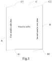
- the metallic middle frame may commonly include two metallic side plates and one metallic baffle.
- a long side A1 of a first metallic side plate A and a first long side C1 of a metallic baffle C are connected to each other
- a long side B1 of a second metallic side plate B and a second long side C2 of a metallic baffle C are connected to each other
- a first metallic side plate A and a second metallic side plate B are positioned at the same side of the metallic baffle C and are respectively perpendicular to the metallic baffle.
- the present disclosure provides a middle frame of mobile terminal and a mobile terminal.
- a middle frame of a mobile terminal comprises a first non-metallic side plate, a second non-metallic side plate and a metallic baffle.
- a long side of the first non-metallic side plate and a first long side of the metallic baffle are connected to each other, a long side of the second non-metallic side plate and a second long side of the metallic baffle are connected to each other, the first non-metallic side plate and the second non-metallic side plate are positioned at a same side of the metallic baffle and respectively perpendicular to the metallic baffle.
- a mobile terminal comprises the middle frame of the mobile terminal according to the above-mentioned first aspect.
- the middle frame of the mobile terminal comprises a first side plate, a second side plate and a metallic baffle, and the first side plate comprises a first metallic portion and a first non-metallic portion, the second side plate comprises a second metallic portion and a second non-metallic portion.
- a long side of the first metallic portion and a first long side of the metallic baffle are connected to each other, a side in the first metallic portion opposite the long side of the first metallic portion is provided with the first non-metallic portion, a long side of the second metallic portion and a second long side of the metallic baffle are connected to each other, and a side of the second metallic portion opposite the long side of the second metallic portion is provided with the second non-metallic portion.
- each of the first metallic portion and the first non-metallic portion is a cuboid side plate.
- each of the second metallic portion and the second non-metallic portion is cuboid side plate.
- the first metallic portion comprises at least one groove structure
- the first non-metallic portion comprises at least one protrusion structure
- the at least one protrusion structure of the first non-metallic portion is imbedded in the at least one groove structure of the first metallic portion.
- the second metallic portion comprises at least one groove structure
- the second non-metallic portion comprises at least one protrusion structure
- the at least one protrusion structure of the second non-metallic portion is imbedded in the at least one groove structure of the second metallic portion.
- each of the at least one groove structures of the first metallic portion has an opening positioned corresponding to the position of a touch sensor of the mobile terminal
- each of the at least one groove structures of the second metallic portion has an opening positioned corresponding to the position of the touch sensor of the mobile terminal.
- a mobile terminal which mobile terminal comprises the middle frame of mobile terminal according to any one selected from the above aspects.
- the technical solutions provided by the present disclosure may include the following advantageous effects: since the middle frame of the mobile terminal comprises the first non-metallic side plate and the second non-metallic side plate, when the mobile terminal is gathering the touch control signal, the first non-metallic side plate and the second non-metallic side plate will not shield the touch control signal, such that the mobile terminal can easily gather the touch control signal improving the efficiency for gathering the touch control signal, and improving the accuracy for gathering the touch control signal at the same time.
- the screen size of the mobile terminal is becoming larger and larger.
- a large screen may provide a broader operative space and screen sight for a user, the one-hand operative of the mobile terminal for the user is becoming lower.
- edge touch control is being added into the mobile terminal gradually.
- the touch control signal for acting the edge touch control is obtained through the detection of a touch sensor of the mobile terminal.
- a metallic middle frame is commonly adopted as the middle frame of mobile terminal.
- the embodiment of the present disclosure provides a middle frame of mobile terminal, so as to improve the efficiency and accuracy for the gathered touch signal of the mobile terminal.
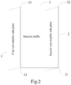
- Fig. 2 is a structural schematic view showing a middle frame of mobile terminal according to an exemplary embodiment.
- the middle frame of mobile terminal comprises a first non-metallic side plate 1, a second non-metallic side plate 2 and a metallic baffle 3.
- a long side 11 of the first non-metallic side plate 1 and a first long side 31 of the metallic baffle 3 are connected to each other, a long side 21 of the second non-metallic side plate 2 and a second long side 32 of the metallic baffle 3 are connected to each other, the first non-metallic side plate 1 and the second non-metallic side plate 2 are positioned at the same side of the metallic baffle 3 and are respectively perpendicular to the metallic baffle 3.
- the middle frame of mobile terminal comprises the first non-metallic side plate 1 and the second non-metallic side plate 2, i.e., the both side plates in the middle frame of mobile terminal are non-metallic side plates
- the first non-metallic side plate 1 and second non-metallic side plate 2 decrease the shielding to the touch control signal, such that the mobile terminal can easily gather the touch control signal, improving the efficiency for gathering the touch control signal, and the accuracy for gathering the touch control signal.
- first non-metallic side plate 1 can be formed by a inject-moulding material and, of course, can be formed by other non-metallic materials, such as ceramics, glass, and etc.
- the embodiments of the present disclosure are not limited to this.
- the second non-metallic side plate 2 can be formed by the inject-moulding material or other non-metallic materials, as well.
- the embodiments of the present disclosure are not limited to this.
- first non-metallic side plate 1 and the second non-metallic side plate 2 may be respectively perpendicular to the metallic side plate 3, and, of course, may be not perpendicular thereto.
- the embodiments of the present disclosure are not limited to this.
- the middle frame of mobile terminal comprises the first non-metallic side plate and the second non-metallic side plate, and the first non-metallic side plate and the second non-metallic side plate are formed by the non-metallic material, the first non-metallic side plate and second non-metallic material decrease the shielding to the touch control signal. Therefore, when the mobile terminal is gathering the touch control signal, the touch control signal may be easily gathered, improving the efficiency for gathering the touch control signal, and improving the accuracy for gathering the touch control signal at the same time.
- the embodiment of the present disclosure provides a mobile terminal, which mobile terminal comprises the middle frame of mobile terminal provided by the above embodiment.
- the mobile terminal may not only comprise the middle frame of mobile terminal of the above embodiment, but also comprise a touch sensor and other elements, such as, a processor, an antenna, etc.
- a touch sensor and other elements, such as, a processor, an antenna, etc.
- the embodiments of the present disclosure are not limited to this.
- the mobile terminal since the mobile terminal comprises the middle frame of mobile terminal for easily gathering the touch control signal, the mobile terminal can gather the touch control signal easily, so as to improve the efficiency for gathering the touch control signal.
- Fig. 3 is a structural schematic view showing another middle frame of mobile terminal according to an exemplary embodiment.
- the middle frame of mobile terminal comprises a first side plate 4, a second side plate 5 and a metallic baffle 3
- the first side plate 4 comprises a first metallic portion 41 and a first non-metallic portion 42
- the second side plate 5 comprises a second metallic portion 51 and a second non-metallic portion 52.
- a long side 411 of the first metallic portion 41 and a first long side 31 of the metallic baffle 3 are connected to each other.
- a side of the first metallic portion 41 opposite the long side 411 of the first metallic portion 41 is provided with a first non-metallic portion 42.
- a long side 511 of the second metallic portion 51 and a second long side 32 of the metallic baffle 3 are connected to each other.
- a side of the second metallic portion 51 opposite the long side 511 of the second metallic portion 51 is provided with a second non-metallic portion 52.
- the first side plate 4 comprises the first non-metallic portion 42
- the second side plate 5 comprises the second non-metallic portion 52
- the first non-metallic portion 42 is positioned at the side opposite the long side 411 of the first metallic portion 41
- the second non-metallic portion 52 is positioned at the side opposite the long side 511 of the second metallic portion 51, i.e., the first non-metallic portion 42 is the portion in the first side plate 4 distant to the metallic baffle 3
- the second non-metallic portion 52 is the portion in the second side plate 5 distant to the metallic baffle 3
- the first side plate 4 and the second side plate 5 may decrease the shielding to the touch control signal, such that the mobile terminal may gather the touch control signal easily, improving the efficiency for gathering the touch control signal.
- the first side plate 4 comprises the first metallic portion 41
- the second side plate 5 comprises the second metallic portion 51
- the first side plate 4 and the second side plate 5 can ensure the sturdy structure for the middle frame of mobile terminal and, at the same time, can effectively prevent the static electricity generated at the battery side from entering the touch control assembly, so as to improve the accuracy for gathering the touch control signal.
- first non-metallic portion 42 is positioned at the side opposite the long side 411 of the first metallic portion 41, and the second non-metallic portion 52 is positioned at the side opposite the long side 511 of the second metallic portion 51
- first metallic portion 41 and the first non-metallic portion 42 are in a same plane
- second metallic portion 51 and the second non-metallic portion 52 are in another same plane.
- the first non-metallic portion 42 may be formed by injection-moulding material, ceramic, glass and other non-metallic materials.
- the embodiments of the present disclosure are not limited to this.
- the second non-metallic portion 52 may be formed by injection-moulding material, ceramic, glass and other non-metallic materials, as well.
- the embodiments of the present disclosure are not limited to this.
- each of the first metallic portion 41 and the first non-metallic portion 42 is a cuboid side plate.
- each of the second metallic portion 51 and the second non-metallic portion 52 is a cuboid side plate.
- the middle frame of mobile terminal can be conveniently mounted, and the appurtenance of the mobile terminal can be ensured to an extent.
- the side surface of the first metallic portion 41 and the first non-metallic portion 42 may be a cuboid side plate, and may be a side plate of other shapes, as well.
- the embodiments of the present disclosure are not limited to this.
- the side surface of the second metallic portion 51 and the second non-metallic portion 52 may be a cuboid side plate, and may be a side plate of other shapes, as well.
- the embodiments of the present disclosure are not limited to this.
- Fig. 4 is a side view showing a first side plate according to an exemplary embodiment. Please refer to Fig. 4 , in which the first metallic portion 41 comprises at least one groove structure, the first non-metallic portion 42 comprises at least one protrusion structure, and the at least one protrusion structure of the first non-metallic portion 42 is imbedded in the at least one groove structure of the first metallic portion 41.
- the middle frame of mobile terminal has a sturdy structure, such that the elements in the mobile terminal can be well fixed.
- the at least one groove structure may be a groove having a rectangular shape, or having another shape, such as a zigzag shape, a waving shape, and etc.
- the at least one protrusion structure may be a protrusion having a rectangular shape, or having another shape, such as a zigzag shape, a waving shape, and etc.
- the embodiments of the present disclosure are not limited to this.
- Fig. 5 is a side view showing a second side plate according to an exemplary embodiment.
- the second metallic portion 51 comprises at least one groove structure
- the second non-metallic portion 52 comprises at least one protrusion structure
- the at least one protrusion structure of the second non-metallic portion 52 is imbedded in the at least one groove structure of the second metallic portion 51.
- the middle frame of mobile terminal has a sturdy structure, such that the elements in the mobile terminal can be well fixed.
- the at least one groove structure may be a groove having a rectangular shape, or having another shape, such as a zigzag shape, a waving shape, and etc.
- the at least one protrusion structure may be a protrusion having a rectangular shape, or having another shape, such as a zigzag shape, a waving shape, and etc.
- the embodiments of the present disclosure are not limited to this.
- the embodiments of the present disclosure are not specifically limited to the shapes of the first non-metallic portion 42 and the first metallic portion 41, so long as the touch sensor 6 is close to the first non-metallic portion 42 and distant from the first metallic portion 41.
- the embodiments of the present disclosure are not specifically limited to the shapes of the second non-metallic portion 52 and the second metallic portion 51, so long as the touch sensor 6 is close to the second non-metallic portion 52 and distant from the second metallic portion 51.
- each of the at least one groove structure of the first metallic portion 41 has an opening positioned corresponding to the position of one of the touch sensors 6 of the mobile terminal.
- each of the at least one groove structure of the second metallic portion 51 has an opening positioned corresponding to the position of one of the touch sensors 6 of the mobile terminal.
- the touch sensors are positioned at the openings of each of the at least one groove structures of the first metallic portion 41, and the touch sensors are positioned at the openings of each of the at least one groove structure of the second metallic portion 5, i.e., the first non-metallic portion 42 is provided with the touch sensors 6 correspondingly, and the second non-metallic portion 52 is provided with the touch sensors 6 correspondingly, as well.
- the touch sensor 6 when the touch sensor 6 is positioned at the opening of each of the groove structures, the touch sensor 6 has a position corresponding to that of the first non-metallic portion 42, and the touch sensor is positioned relatively distant from the first metallic portion 41, so as to decrease the shielding to the touch control signal caused by the first metallic portion.
- the touch sensor 6 when the touch sensor 6 is positioned in the opening of each of the groove structures of the second metallic portion, the touch sensor 6 has a position corresponding to that of the second non-metallic portion, and the touch sensor 6 is positioned relatively distant from the second metallic portion, so as to decrease the shielding to the touch control signal caused by the second metallic portion, and the efficiency of the mobile terminal for gathering the touch control signal can be improved.
- the first side plate comprises the first non-metallic portion
- the second side plate comprises the second non-metallic portion
- the first non-metallic portion is positioned at the side opposite the long side of the first metallic portion
- the second non-metallic portion is positioned at the side opposite the long side of the second metallic portion, i.e., the first non-metallic portion is the portion in the first side plate distant from the metallic baffle
- the second non-metallic portion is the portion in the second side plate distant from the metallic baffle
- the first side plate comprises the first metallic portion
- the second side plate comprises the second metallic portion
- the first side plate and the second side plate can ensure the sturdy structure of the middle frame of mobile terminal and, at the same time, can effectively prevent the static current generated at the battery side from entering the touch control assembly, so as to improve the accuracy for gathering the touch control signal.
- the embodiment of the present disclosure provides a mobile terminal, which mobile terminal comprises the middle frame of mobile terminal provided by the above-mentioned embodiments.
- the mobile terminal further comprises the touch sensor provided by the above-mentioned embodiments.
- the mobile terminal may not only comprise the middle frame of mobile terminal and the touch sensor of the above-mentioned embodiment, but also comprise other elements, such as, a processor, an antenna, and etc.
- the embodiments of the present disclosure are not limited to this.
- the mobile terminal since the mobile terminal comprises the middle frame of mobile terminal for easily gathering the touch control signal, the mobile terminal can gather the touch control signal easily, so as to improve the efficiency for gathering the touch control signal.
Landscapes
- Engineering & Computer Science (AREA)
- Signal Processing (AREA)
- Microelectronics & Electronic Packaging (AREA)
- General Engineering & Computer Science (AREA)
- Theoretical Computer Science (AREA)
- Computer Networks & Wireless Communication (AREA)
- Human Computer Interaction (AREA)
- Physics & Mathematics (AREA)
- General Physics & Mathematics (AREA)
- Telephone Set Structure (AREA)
Abstract
Description
- The disclosure relates generally to the art of mobile terminals and, more particularly, to a middle frame of mobile terminal and a mobile terminal.
- With the development of the terminal technology, screen sizes of the mobile terminals are larger and larger. Though a large screen may provide a broader operative space and screen sight for a user, the one-hand operative of the mobile terminal for the user is becoming lower. Thus, edge touch control is coming into sight. However, the touch control signal for acting the edge touch control is obtained through the detection of a touch sensor of the mobile terminal, and the strength of the touch control signal is dependent from the middle frame of mobile terminal. The middle frame of mobile terminal means a structure for separating a touch control assembly and a battery of the mobile terminal, wherein the touch sensor is included in the touch control assembly.
- In the related arts, in order to prevent the static electricity generated at the battery side from entering the touch control assembly and causing undesirable effects to the touch control assembly, a metallic middle frame is commonly adopted as the middle frame of mobile terminal. Please refer to
Fig. 1 , in which the metallic middle frame may commonly include two metallic side plates and one metallic baffle. Here, a long side A1 of a first metallic side plate A and a first long side C1 of a metallic baffle C are connected to each other, a long side B1 of a second metallic side plate B and a second long side C2 of a metallic baffle C are connected to each other, and a first metallic side plate A and a second metallic side plate B are positioned at the same side of the metallic baffle C and are respectively perpendicular to the metallic baffle. - To overcome the problems existing in the relative arts, the present disclosure provides a middle frame of mobile terminal and a mobile terminal.
- According to a first aspect of the embodiments of the present disclosure, there is provided a middle frame of a mobile terminal. The middle frame of the mobile terminal comprises a first non-metallic side plate, a second non-metallic side plate and a metallic baffle.
- A long side of the first non-metallic side plate and a first long side of the metallic baffle are connected to each other, a long side of the second non-metallic side plate and a second long side of the metallic baffle are connected to each other, the first non-metallic side plate and the second non-metallic side plate are positioned at a same side of the metallic baffle and respectively perpendicular to the metallic baffle.
- According to a second aspect of the embodiments of the present disclosure, there is provided a mobile terminal. The mobile terminal comprises the middle frame of the mobile terminal according to the above-mentioned first aspect.
- According to a third aspect of the embodiments of the present disclosure, there is provided another middle frame of the mobile terminal. The middle frame of the mobile terminal comprises a first side plate, a second side plate and a metallic baffle, and the first side plate comprises a first metallic portion and a first non-metallic portion, the second side plate comprises a second metallic portion and a second non-metallic portion.
- A long side of the first metallic portion and a first long side of the metallic baffle are connected to each other, a side in the first metallic portion opposite the long side of the first metallic portion is provided with the first non-metallic portion, a long side of the second metallic portion and a second long side of the metallic baffle are connected to each other, and a side of the second metallic portion opposite the long side of the second metallic portion is provided with the second non-metallic portion.
- With reference to the third aspect, in a first possible implement of the above-mentioned third aspect, each of the first metallic portion and the first non-metallic portion is a cuboid side plate.
- With reference to the third aspect or the first possible implement of the third aspect, in a second possible implement of the above-mentioned third aspect, each of the second metallic portion and the second non-metallic portion is cuboid side plate.
- With reference to the third aspect, in a third possible implement of the above-mentioned third aspect, the first metallic portion comprises at least one groove structure, the first non-metallic portion comprises at least one protrusion structure, and the at least one protrusion structure of the first non-metallic portion is imbedded in the at least one groove structure of the first metallic portion.
- With reference to the any one selected from the third aspect to the third possible implement of the third aspect, in a fourth possible implement of the above-mentioned third aspect, the second metallic portion comprises at least one groove structure, the second non-metallic portion comprises at least one protrusion structure, and the at least one protrusion structure of the second non-metallic portion is imbedded in the at least one groove structure of the second metallic portion.
- With reference to the third or fourth possible implement of the third aspect, in a fifth possible implement of the above-mentioned third aspect, each of the at least one groove structures of the first metallic portion has an opening positioned corresponding to the position of a touch sensor of the mobile terminal, each of the at least one groove structures of the second metallic portion has an opening positioned corresponding to the position of the touch sensor of the mobile terminal.
- According to a fourth aspect of the embodiments of the present disclosure, there is provided a mobile terminal, which mobile terminal comprises the middle frame of mobile terminal according to any one selected from the above aspects.
- The technical solutions provided by the present disclosure may include the following advantageous effects: since the middle frame of the mobile terminal comprises the first non-metallic side plate and the second non-metallic side plate, when the mobile terminal is gathering the touch control signal, the first non-metallic side plate and the second non-metallic side plate will not shield the touch control signal, such that the mobile terminal can easily gather the touch control signal improving the efficiency for gathering the touch control signal, and improving the accuracy for gathering the touch control signal at the same time.
- It is to be understood that both the foregoing general description and the following detailed description are exemplary and explanatory only and are not restrictive of the disclosure.
- The accompanying drawings, which are incorporated in and constitute a part of this specification, illustrate embodiments consistent with the disclosure and, together with the description, serve to explain the principles of the disclosure.
-
Fig. 1 is a structural schematic view showing a metallic middle frame according to an exemplary embodiment. -
Fig. 2 is a structural schematic view showing a middle frame of mobile terminal according to an exemplary embodiment. -
Fig. 3 is a structural schematic view showing another middle frame of mobile terminal according to an exemplary embodiment. -
Fig. 4 is a side view showing a first side plate according to an exemplary embodiment. -
Fig. 5 is a side view showing a second side plate according to an exemplary embodiment. -
Fig. 6 is a figure showing the positional relationship between a first metallic portion and a touch sensor according to an exemplary embodiment. -
Fig. 7 is a figure showing the positional relationship between a second metallic portion and a touch sensor according to an exemplary embodiment. -
- A:
- first metallic side plate;
- B:
- second metallic side plate;
- C:
- metallic baffle;
- A1:
- long side of the first metallic side plate;
- B1:
- long side of the second metallic side plate;
- C1:
- first long side of the metallic baffle;
- C2:
- second long side of the metallic baffle;
- 1:
- first non-metallic side plate;
- 2:
- second non-metallic side plate;
- 3:
- metallic baffle;
- 11:
- long side of the first non-metallic side plate;
- 21:
- long side of the second non-metallic side plate;
- 31:
- first long side of the metallic baffle;
- 32:
- second long side of the metallic baffle;
- 4:
- first side plate;
- 5:
- second side plate;
- 6:
- touch sensor;
- 41:
- first metallic portion;
- 42:
- first non-metallic portion;
- 51:
- second metallic portion;
- 52:
- second non-metallic portion;
- 411:
- long side of the first metallic portion;
- 511:
- long side of the second metallic portion.
- Reference will now be made in detail to exemplary embodiments, examples of which are illustrated in the accompanying drawings. The following description refers to the accompanying drawings in which the same numbers in different drawings represent the same or similar elements unless otherwise represented. The implementations set forth in the following description of exemplary embodiments do not represent all implementations consistent with the disclosure. Instead, they are merely examples of devices and methods consistent with some aspects related to the disclosure as recited in the appended claims.
- An application environment of the present disclosure will be introduced before the detailed explanation to the embodiments of the present disclosure. At present, the screen size of the mobile terminal is becoming larger and larger. Though a large screen may provide a broader operative space and screen sight for a user, the one-hand operative of the mobile terminal for the user is becoming lower. To solve this problem, edge touch control is being added into the mobile terminal gradually. Here, the touch control signal for acting the edge touch control is obtained through the detection of a touch sensor of the mobile terminal. At the same time, in order to prevent the static electricity generated at the battery side from entering the touch control assembly, a metallic middle frame is commonly adopted as the middle frame of mobile terminal. However, since the metallic middle frame shields the touch control signal to an extent, a part of the touch signal may be shielded when the metallic middle frame is preventing the static electricity from entering the touch control assembly, causing a decreased efficiency and accuracy for the gathered touch signal of the mobile terminal. Thus, the embodiment of the present disclosure provides a middle frame of mobile terminal, so as to improve the efficiency and accuracy for the gathered touch signal of the mobile terminal.
-
Fig. 2 is a structural schematic view showing a middle frame of mobile terminal according to an exemplary embodiment. As show inFig. 2 , the middle frame of mobile terminal comprises a first non-metallic side plate 1, a second non-metallic side plate 2 and ametallic baffle 3. - A
long side 11 of the first non-metallic side plate 1 and a firstlong side 31 of themetallic baffle 3 are connected to each other, along side 21 of the second non-metallic side plate 2 and a secondlong side 32 of themetallic baffle 3 are connected to each other, the first non-metallic side plate 1 and the second non-metallic side plate 2 are positioned at the same side of themetallic baffle 3 and are respectively perpendicular to themetallic baffle 3. - Since the middle frame of mobile terminal comprises the first non-metallic side plate 1 and the second non-metallic side plate 2, i.e., the both side plates in the middle frame of mobile terminal are non-metallic side plates, when the mobile terminal is gathering the touch control signal, the first non-metallic side plate 1 and second non-metallic side plate 2 decrease the shielding to the touch control signal, such that the mobile terminal can easily gather the touch control signal, improving the efficiency for gathering the touch control signal, and the accuracy for gathering the touch control signal.
- It should be noted that, first non-metallic side plate 1 can be formed by a inject-moulding material and, of course, can be formed by other non-metallic materials, such as ceramics, glass, and etc. The embodiments of the present disclosure are not limited to this.
- For the similar reason, the second non-metallic side plate 2 can be formed by the inject-moulding material or other non-metallic materials, as well. The embodiments of the present disclosure are not limited to this.
- It should be also noted that, in the embodiment of the present disclosure, the first non-metallic side plate 1 and the second non-metallic side plate 2 may be respectively perpendicular to the
metallic side plate 3, and, of course, may be not perpendicular thereto. The embodiments of the present disclosure are not limited to this. - In the embodiments of the present disclosure, since the middle frame of mobile terminal comprises the first non-metallic side plate and the second non-metallic side plate, and the first non-metallic side plate and the second non-metallic side plate are formed by the non-metallic material, the first non-metallic side plate and second non-metallic material decrease the shielding to the touch control signal. Therefore, when the mobile terminal is gathering the touch control signal, the touch control signal may be easily gathered, improving the efficiency for gathering the touch control signal, and improving the accuracy for gathering the touch control signal at the same time.
- The embodiment of the present disclosure provides a mobile terminal, which mobile terminal comprises the middle frame of mobile terminal provided by the above embodiment.
- It should be noted that, the mobile terminal may not only comprise the middle frame of mobile terminal of the above embodiment, but also comprise a touch sensor and other elements, such as, a processor, an antenna, etc. The embodiments of the present disclosure are not limited to this.
- In the embodiments of the present disclosure, since the mobile terminal comprises the middle frame of mobile terminal for easily gathering the touch control signal, the mobile terminal can gather the touch control signal easily, so as to improve the efficiency for gathering the touch control signal.
-
Fig. 3 is a structural schematic view showing another middle frame of mobile terminal according to an exemplary embodiment. Please refer toFig. 3 , in which the middle frame of mobile terminal comprises afirst side plate 4, asecond side plate 5 and ametallic baffle 3, and thefirst side plate 4 comprises a firstmetallic portion 41 and a firstnon-metallic portion 42, thesecond side plate 5 comprises a secondmetallic portion 51 and a secondnon-metallic portion 52. - A
long side 411 of the firstmetallic portion 41 and a firstlong side 31 of themetallic baffle 3 are connected to each other. A side of the firstmetallic portion 41 opposite thelong side 411 of the firstmetallic portion 41 is provided with a firstnon-metallic portion 42. Along side 511 of the secondmetallic portion 51 and a secondlong side 32 of themetallic baffle 3 are connected to each other. A side of the secondmetallic portion 51 opposite thelong side 511 of the secondmetallic portion 51 is provided with a secondnon-metallic portion 52. - Since the
first side plate 4 comprises the firstnon-metallic portion 42, thesecond side plate 5 comprises the secondnon-metallic portion 52, and the firstnon-metallic portion 42 is positioned at the side opposite thelong side 411 of the firstmetallic portion 41, the secondnon-metallic portion 52 is positioned at the side opposite thelong side 511 of the secondmetallic portion 51, i.e., the firstnon-metallic portion 42 is the portion in thefirst side plate 4 distant to themetallic baffle 3, and the secondnon-metallic portion 52 is the portion in thesecond side plate 5 distant to themetallic baffle 3, when the mobile terminal is gathering the touch control signal, thefirst side plate 4 and thesecond side plate 5 may decrease the shielding to the touch control signal, such that the mobile terminal may gather the touch control signal easily, improving the efficiency for gathering the touch control signal. At the same time, since thefirst side plate 4 comprises the firstmetallic portion 41, and thesecond side plate 5 comprises the secondmetallic portion 51, thefirst side plate 4 and thesecond side plate 5 can ensure the sturdy structure for the middle frame of mobile terminal and, at the same time, can effectively prevent the static electricity generated at the battery side from entering the touch control assembly, so as to improve the accuracy for gathering the touch control signal. - Here, when the first
non-metallic portion 42 is positioned at the side opposite thelong side 411 of the firstmetallic portion 41, and the secondnon-metallic portion 52 is positioned at the side opposite thelong side 511 of the secondmetallic portion 51, the firstmetallic portion 41 and the firstnon-metallic portion 42 are in a same plane, and the secondmetallic portion 51 and the secondnon-metallic portion 52 are in another same plane. - It should be noted that, the first
non-metallic portion 42 may be formed by injection-moulding material, ceramic, glass and other non-metallic materials. The embodiments of the present disclosure are not limited to this. - It should be also noted that, the second
non-metallic portion 52 may be formed by injection-moulding material, ceramic, glass and other non-metallic materials, as well. The embodiments of the present disclosure are not limited to this. - Please refer to
Fig. 3 , in which each of the firstmetallic portion 41 and the firstnon-metallic portion 42 is a cuboid side plate. For the similar reason, each of the secondmetallic portion 51 and the secondnon-metallic portion 52 is a cuboid side plate. - It should be noted that, when each of the first
metallic portion 41 and the firstnon-metallic portion 42 is the cuboid side plate, and each of the secondmetallic portion 51 and the secondnon-metallic portion 52 the cuboid side plate, the middle frame of mobile terminal can be conveniently mounted, and the appurtenance of the mobile terminal can be ensured to an extent. - It should be also noted that, the side surface of the first
metallic portion 41 and the firstnon-metallic portion 42 may be a cuboid side plate, and may be a side plate of other shapes, as well. The embodiments of the present disclosure are not limited to this. - For the similar reason, the side surface of the second
metallic portion 51 and the secondnon-metallic portion 52 may be a cuboid side plate, and may be a side plate of other shapes, as well. The embodiments of the present disclosure are not limited to this. -
Fig. 4 is a side view showing a first side plate according to an exemplary embodiment. Please refer toFig. 4 , in which the firstmetallic portion 41 comprises at least one groove structure, the firstnon-metallic portion 42 comprises at least one protrusion structure, and the at least one protrusion structure of the firstnon-metallic portion 42 is imbedded in the at least one groove structure of the firstmetallic portion 41. - Here, when the at least one protrusion structure of the first
non-metallic portion 42 is imbedded in the at least one groove structure of the firstmetallic portion 41, the middle frame of mobile terminal has a sturdy structure, such that the elements in the mobile terminal can be well fixed. - It should be noted that, the at least one groove structure may be a groove having a rectangular shape, or having another shape, such as a zigzag shape, a waving shape, and etc. Similarly, the at least one protrusion structure may be a protrusion having a rectangular shape, or having another shape, such as a zigzag shape, a waving shape, and etc. The embodiments of the present disclosure are not limited to this.
- In addition,
Fig. 5 is a side view showing a second side plate according to an exemplary embodiment. Similarly, the secondmetallic portion 51 comprises at least one groove structure, the secondnon-metallic portion 52 comprises at least one protrusion structure, and the at least one protrusion structure of the secondnon-metallic portion 52 is imbedded in the at least one groove structure of the secondmetallic portion 51. - Here, when the at least one protrusion structure of the second
non-metallic portion 52 is imbedded in the at least one groove structure of the secondmetallic portion 51, the middle frame of mobile terminal has a sturdy structure, such that the elements in the mobile terminal can be well fixed. - It should be noted that, the at least one groove structure may be a groove having a rectangular shape, or having another shape, such as a zigzag shape, a waving shape, and etc. Similarly, the at least one protrusion structure may be a protrusion having a rectangular shape, or having another shape, such as a zigzag shape, a waving shape, and etc. The embodiments of the present disclosure are not limited to this.
- It should be also noted that, based on the above description, the embodiments of the present disclosure are not specifically limited to the shapes of the first
non-metallic portion 42 and the firstmetallic portion 41, so long as thetouch sensor 6 is close to the firstnon-metallic portion 42 and distant from the firstmetallic portion 41. For the similar reason, the embodiments of the present disclosure are not specifically limited to the shapes of the secondnon-metallic portion 52 and the secondmetallic portion 51, so long as thetouch sensor 6 is close to the secondnon-metallic portion 52 and distant from the secondmetallic portion 51. - Please refer to
Fig. 6 , in which each of the at least one groove structure of the firstmetallic portion 41 has an opening positioned corresponding to the position of one of thetouch sensors 6 of the mobile terminal. Please refer toFig. 7 , in which each of the at least one groove structure of the secondmetallic portion 51 has an opening positioned corresponding to the position of one of thetouch sensors 6 of the mobile terminal. - Here, the touch sensors are positioned at the openings of each of the at least one groove structures of the first
metallic portion 41, and the touch sensors are positioned at the openings of each of the at least one groove structure of the secondmetallic portion 5, i.e., the firstnon-metallic portion 42 is provided with thetouch sensors 6 correspondingly, and the secondnon-metallic portion 52 is provided with thetouch sensors 6 correspondingly, as well. - It should be noted that, when the
touch sensor 6 is positioned at the opening of each of the groove structures, thetouch sensor 6 has a position corresponding to that of the firstnon-metallic portion 42, and the touch sensor is positioned relatively distant from the firstmetallic portion 41, so as to decrease the shielding to the touch control signal caused by the first metallic portion. For the similar reason, when thetouch sensor 6 is positioned in the opening of each of the groove structures of the second metallic portion, thetouch sensor 6 has a position corresponding to that of the second non-metallic portion, and thetouch sensor 6 is positioned relatively distant from the second metallic portion, so as to decrease the shielding to the touch control signal caused by the second metallic portion, and the efficiency of the mobile terminal for gathering the touch control signal can be improved. - In the embodiments of the present disclosure, since the first side plate comprises the first non-metallic portion, the second side plate comprises the second non-metallic portion, and the first non-metallic portion is positioned at the side opposite the long side of the first metallic portion, the second non-metallic portion is positioned at the side opposite the long side of the second metallic portion, i.e., the first non-metallic portion is the portion in the first side plate distant from the metallic baffle, and the second non-metallic portion is the portion in the second side plate distant from the metallic baffle, when the mobile terminal is gathering the touch control signal, the first side plate and the second side plate decrease the shielding to the gathering for the touch control signal, such that the mobile terminal can easily gather the touch control signal, and the efficiency of gathering the touch control signal is improved. At the same time, since the first side plate comprises the first metallic portion, and the second side plate comprises the second metallic portion, the first side plate and the second side plate can ensure the sturdy structure of the middle frame of mobile terminal and, at the same time, can effectively prevent the static current generated at the battery side from entering the touch control assembly, so as to improve the accuracy for gathering the touch control signal.
- The embodiment of the present disclosure provides a mobile terminal, which mobile terminal comprises the middle frame of mobile terminal provided by the above-mentioned embodiments.
- Here, the mobile terminal further comprises the touch sensor provided by the above-mentioned embodiments.
- It should be noted that, the mobile terminal may not only comprise the middle frame of mobile terminal and the touch sensor of the above-mentioned embodiment, but also comprise other elements, such as, a processor, an antenna, and etc. The embodiments of the present disclosure are not limited to this.
- In the embodiments of the present disclosure, since the mobile terminal comprises the middle frame of mobile terminal for easily gathering the touch control signal, the mobile terminal can gather the touch control signal easily, so as to improve the efficiency for gathering the touch control signal.
Claims (9)
- A middle frame of a mobile terminal, characterized in that the middle frame of mobile terminal comprises a first non-metallic side plate (1), a second non-metallic side plate (2) and a metallic baffle (3);
a long side (11) of the first non-metallic side plate (1) and a first long side (31) of the metallic baffle (3) are connected to each other, a long side (21) of the second non-metallic side plate (2) and a second long side (32) of the metallic baffle (3) are connected to each other, and the first non-metallic side plate (1) and the second non-metallic side plate (2) are positioned at a same side of the metallic baffle (3) and respectively perpendicular to the metallic baffle (3). - A mobile terminal, characterized in that the mobile terminal comprises the middle frame according to claim 1.
- A middle frame of a mobile terminal, characterized in that the middle frame of mobile terminal comprises a first side plate (4), a second side plate (5) and a metallic baffle (3), and the first side plate (4) comprises a first metallic portion (41) and a first non-metallic portion (42), the second side plate (5) comprises a second metallic portion (51) and a second non-metallic portion (52);
a long side (411) of the first metallic portion (41) and a first long side (31) of the metallic baffle (3) are connected to each other, a side in the first metallic portion (41) opposite the long side (411) of the first metallic portion (41) is provided with the first non-metallic portion (42), a long side (511) of the second metallic portion (51) and a second long side (32) of the metallic baffle (3) are connected to each other, and a side of the second metallic portion (51) opposite the long side (511) of the second metallic portion (51) is provided with the second non-metallic portion (52). - The middle frame of mobile terminal according to claim 3, characterized in that each of the first metallic portion (41) and the first non-metallic portion (42) is a cuboid side plate.
- The middle frame of mobile terminal according to claim 3 or 4, characterized in that each of the second metallic portion (51) and the second non-metallic portion (52) is cuboid side plate.
- The middle frame of mobile terminal according to claim 3, characterized in that the first metallic portion (41) comprises at least one groove structure, the first non-metallic portion (42) comprises at least one protrusion structure, and the at least one protrusion structure of the first non-metallic portion (42) is imbedded in the at least one groove structure of the first metallic portion (41).
- The middle frame of mobile terminal according to any one of claims 3-6, characterized in that the second metallic portion (51) comprises at least one groove structure, the second non-metallic portion (52) comprises at least one protrusion structure, and the at least one protrusion structure of the second non-metallic portion (52) is imbedded in the at least one groove structure of the second metallic portion (51).
- The middle frame of mobile terminal according to claim 6 or 7, characterized in that each of the at least one groove structures of the first metallic portion (41) has an opening positioned corresponding to the position of a touch sensor (6) of the mobile terminal, each of the at least one groove structures of the second metallic portion (51) has an opening positioned corresponding to the position of the touch sensor (6) of the mobile terminal.
- A mobile terminal, characterized in that the mobile terminal comprises the middle frame according to any one of claims 3-8.
Applications Claiming Priority (1)
| Application Number | Priority Date | Filing Date | Title |
|---|---|---|---|
| CN201610282788.9A CN107340900B (en) | 2016-04-29 | 2016-04-29 | Mobile terminal middle frame and mobile terminal |
Publications (2)
| Publication Number | Publication Date |
|---|---|
| EP3240373A1 true EP3240373A1 (en) | 2017-11-01 |
| EP3240373B1 EP3240373B1 (en) | 2019-04-03 |
Family
ID=57345730
Family Applications (1)
| Application Number | Title | Priority Date | Filing Date |
|---|---|---|---|
| EP16198912.4A Not-in-force EP3240373B1 (en) | 2016-04-29 | 2016-11-15 | Middle frame of mobile terminal and mobile terminal |
Country Status (7)
| Country | Link |
|---|---|
| US (1) | US10129990B2 (en) |
| EP (1) | EP3240373B1 (en) |
| JP (1) | JP6427204B2 (en) |
| KR (1) | KR101966833B1 (en) |
| CN (1) | CN107340900B (en) |
| RU (1) | RU2660662C2 (en) |
| WO (1) | WO2017185560A1 (en) |
Cited By (1)
| Publication number | Priority date | Publication date | Assignee | Title |
|---|---|---|---|---|
| CN108737613A (en) * | 2018-03-30 | 2018-11-02 | 谢宝金 | One kind can touch screen electronic device protective shell |
Citations (3)
| Publication number | Priority date | Publication date | Assignee | Title |
|---|---|---|---|---|
| EP2176049A2 (en) * | 2007-07-13 | 2010-04-21 | Apple Inc. | Methods and systems for forming a dual layer housing |
| US20120133608A1 (en) * | 2010-11-29 | 2012-05-31 | Inventec Corporation | Touch display assembly structure |
| EP2742674A1 (en) * | 2011-09-27 | 2014-06-18 | Apple Inc. | Electronic devices with sidewall displays |
Family Cites Families (16)
| Publication number | Priority date | Publication date | Assignee | Title |
|---|---|---|---|---|
| US2724047A (en) * | 1952-09-04 | 1955-11-15 | Garden City Plating & Mfg Co | Fluorescent light fixture |
| US7436678B2 (en) * | 2004-10-18 | 2008-10-14 | E.I. Du Pont De Nemours And Company | Capacitive/resistive devices and printed wiring boards incorporating such devices and methods of making thereof |
| US9110580B2 (en) * | 2011-08-05 | 2015-08-18 | Nokia Technologies Oy | Apparatus comprising a display and a method and computer program |
| US8517172B1 (en) * | 2012-10-01 | 2013-08-27 | Match U International Co., Ltd. | Protective housing assembly for electronic devices |
| US9207800B1 (en) * | 2014-09-23 | 2015-12-08 | Neonode Inc. | Integrated light guide and touch screen frame and multi-touch determination method |
| CN203433482U (en) * | 2013-07-30 | 2014-02-12 | 信利半导体有限公司 | Handheld mobile device with touch control display screen |
| CN107613700B (en) * | 2013-08-27 | 2020-12-15 | 华为终端有限公司 | Electronic terminal equipment |
| JP2016046601A (en) * | 2014-08-20 | 2016-04-04 | シャープ株式会社 | Mobile terminal, control program, and mobile terminal control method |
| US9894192B2 (en) * | 2014-09-04 | 2018-02-13 | James L. Cox, III | Case with interchangeable back plate |
| CN204168352U (en) * | 2014-10-28 | 2015-02-18 | 广东欧珀移动通信有限公司 | Metallic mobile phone housing and mobile phone |
| RU155093U1 (en) * | 2014-10-31 | 2015-09-20 | Алексей Николаевич Фролов | MOBILE COMMUNICATION |
| CN204291096U (en) * | 2014-12-30 | 2015-04-22 | 广东欧珀移动通信有限公司 | A kind of metal center mobile terminal |
| CN104853549A (en) * | 2015-04-22 | 2015-08-19 | 奥捷五金(江苏)有限公司 | Mobile electronic product metal middle frame and processing technique thereof |
| CN104850183A (en) * | 2015-05-21 | 2015-08-19 | 小米科技有限责任公司 | Mobile terminal display structure and mobile terminal |
| CN104883841A (en) * | 2015-05-22 | 2015-09-02 | 奥捷五金(江苏)有限公司 | Middle frame structure manufacturing technology and middle frame structure |
| CN105188291A (en) * | 2015-09-14 | 2015-12-23 | 小米科技有限责任公司 | Electronic equipment shell body and electronic equipment |
-
2016
- 2016-04-29 CN CN201610282788.9A patent/CN107340900B/en not_active Expired - Fee Related
- 2016-09-09 RU RU2016145112A patent/RU2660662C2/en active
- 2016-09-09 KR KR1020187000294A patent/KR101966833B1/en not_active Expired - Fee Related
- 2016-09-09 WO PCT/CN2016/094342 patent/WO2017185560A1/en not_active Ceased
- 2016-09-09 JP JP2016564264A patent/JP6427204B2/en not_active Expired - Fee Related
- 2016-11-15 EP EP16198912.4A patent/EP3240373B1/en not_active Not-in-force
-
2017
- 2017-04-24 US US15/494,597 patent/US10129990B2/en active Active
Patent Citations (3)
| Publication number | Priority date | Publication date | Assignee | Title |
|---|---|---|---|---|
| EP2176049A2 (en) * | 2007-07-13 | 2010-04-21 | Apple Inc. | Methods and systems for forming a dual layer housing |
| US20120133608A1 (en) * | 2010-11-29 | 2012-05-31 | Inventec Corporation | Touch display assembly structure |
| EP2742674A1 (en) * | 2011-09-27 | 2014-06-18 | Apple Inc. | Electronic devices with sidewall displays |
Cited By (2)
| Publication number | Priority date | Publication date | Assignee | Title |
|---|---|---|---|---|
| CN108737613A (en) * | 2018-03-30 | 2018-11-02 | 谢宝金 | One kind can touch screen electronic device protective shell |
| CN108737613B (en) * | 2018-03-30 | 2020-08-11 | 台州中知英健机械自动化有限公司 | Touch screen electronic device protective shell |
Also Published As
| Publication number | Publication date |
|---|---|
| RU2016145112A3 (en) | 2018-05-17 |
| US20170318698A1 (en) | 2017-11-02 |
| EP3240373B1 (en) | 2019-04-03 |
| KR101966833B1 (en) | 2019-04-08 |
| KR20180014820A (en) | 2018-02-09 |
| CN107340900A (en) | 2017-11-10 |
| CN107340900B (en) | 2020-09-18 |
| JP6427204B2 (en) | 2018-11-21 |
| RU2660662C2 (en) | 2018-07-09 |
| US10129990B2 (en) | 2018-11-13 |
| WO2017185560A1 (en) | 2017-11-02 |
| RU2016145112A (en) | 2018-05-17 |
| JP2018517309A (en) | 2018-06-28 |
Similar Documents
| Publication | Publication Date | Title |
|---|---|---|
| US10171896B2 (en) | Electronic device with side speaker hole | |
| US10910718B2 (en) | Transparent antenna and transparent antenna-attached display device | |
| KR101946655B1 (en) | Method of disposing sensor in display terminal | |
| CN106603776B (en) | Terminal device | |
| CN103346383B (en) | Loop aerial assembly and there is the electronic equipment of this loop aerial assembly | |
| CN104951132B (en) | Touch display panel structure | |
| CN108111643A (en) | Mobile terminal | |
| EP3240373A1 (en) | Middle frame of mobile terminal and mobile terminal | |
| US10459592B2 (en) | Touch apparatus | |
| CN105633449B (en) | rechargeable battery | |
| CN103336559B (en) | Touch-control module and portable electron device | |
| JP2021526273A (en) | Electromagnetic touch structure, direct backlight display module and display | |
| EP3506420A1 (en) | Electronic device with advanced antenna | |
| WO2014166445A1 (en) | Shielding device | |
| US20160179140A1 (en) | Chassis Design for Wireless-Charging Coil Integration for Computing Systems | |
| CN209526744U (en) | Mobile phone motherboard and mobile phone | |
| CN203706160U (en) | Touch control device | |
| KR20150031981A (en) | Portable terminal | |
| CN209133097U (en) | Comprehensive screen assembly and electronic equipment | |
| CN204335204U (en) | terminal | |
| CN215769285U (en) | Anti-magnetic field interference structure for electronic ink screen module | |
| CN210072351U (en) | Window assembly and electronic instrument | |
| CN203616733U (en) | Touch device | |
| CN105868729A (en) | Press button device and terminal | |
| CN206179735U (en) | Button device of fixed fastness of reinforcing |
Legal Events
| Date | Code | Title | Description |
|---|---|---|---|
| PUAI | Public reference made under article 153(3) epc to a published international application that has entered the european phase |
Free format text: ORIGINAL CODE: 0009012 |
|
| STAA | Information on the status of an ep patent application or granted ep patent |
Free format text: STATUS: THE APPLICATION HAS BEEN PUBLISHED |
|
| AK | Designated contracting states |
Kind code of ref document: A1 Designated state(s): AL AT BE BG CH CY CZ DE DK EE ES FI FR GB GR HR HU IE IS IT LI LT LU LV MC MK MT NL NO PL PT RO RS SE SI SK SM TR |
|
| AX | Request for extension of the european patent |
Extension state: BA ME |
|
| STAA | Information on the status of an ep patent application or granted ep patent |
Free format text: STATUS: REQUEST FOR EXAMINATION WAS MADE |
|
| 17P | Request for examination filed |
Effective date: 20180426 |
|
| RBV | Designated contracting states (corrected) |
Designated state(s): AL AT BE BG CH CY CZ DE DK EE ES FI FR GB GR HR HU IE IS IT LI LT LU LV MC MK MT NL NO PL PT RO RS SE SI SK SM TR |
|
| GRAP | Despatch of communication of intention to grant a patent |
Free format text: ORIGINAL CODE: EPIDOSNIGR1 |
|
| STAA | Information on the status of an ep patent application or granted ep patent |
Free format text: STATUS: GRANT OF PATENT IS INTENDED |
|
| INTG | Intention to grant announced |
Effective date: 20181015 |
|
| GRAS | Grant fee paid |
Free format text: ORIGINAL CODE: EPIDOSNIGR3 |
|
| GRAA | (expected) grant |
Free format text: ORIGINAL CODE: 0009210 |
|
| STAA | Information on the status of an ep patent application or granted ep patent |
Free format text: STATUS: THE PATENT HAS BEEN GRANTED |
|
| AK | Designated contracting states |
Kind code of ref document: B1 Designated state(s): AL AT BE BG CH CY CZ DE DK EE ES FI FR GB GR HR HU IE IS IT LI LT LU LV MC MK MT NL NO PL PT RO RS SE SI SK SM TR |
|
| REG | Reference to a national code |
Ref country code: GB Ref legal event code: FG4D |
|
| REG | Reference to a national code |
Ref country code: CH Ref legal event code: EP Ref country code: AT Ref legal event code: REF Ref document number: 1117387 Country of ref document: AT Kind code of ref document: T Effective date: 20190415 |
|
| REG | Reference to a national code |
Ref country code: DE Ref legal event code: R096 Ref document number: 602016011823 Country of ref document: DE |
|
| REG | Reference to a national code |
Ref country code: IE Ref legal event code: FG4D |
|
| REG | Reference to a national code |
Ref country code: NL Ref legal event code: MP Effective date: 20190403 |
|
| REG | Reference to a national code |
Ref country code: LT Ref legal event code: MG4D |
|
| REG | Reference to a national code |
Ref country code: AT Ref legal event code: MK05 Ref document number: 1117387 Country of ref document: AT Kind code of ref document: T Effective date: 20190403 |
|
| PG25 | Lapsed in a contracting state [announced via postgrant information from national office to epo] |
Ref country code: NL Free format text: LAPSE BECAUSE OF FAILURE TO SUBMIT A TRANSLATION OF THE DESCRIPTION OR TO PAY THE FEE WITHIN THE PRESCRIBED TIME-LIMIT Effective date: 20190403 |
|
| PG25 | Lapsed in a contracting state [announced via postgrant information from national office to epo] |
Ref country code: AL Free format text: LAPSE BECAUSE OF FAILURE TO SUBMIT A TRANSLATION OF THE DESCRIPTION OR TO PAY THE FEE WITHIN THE PRESCRIBED TIME-LIMIT Effective date: 20190403 Ref country code: CZ Free format text: LAPSE BECAUSE OF FAILURE TO SUBMIT A TRANSLATION OF THE DESCRIPTION OR TO PAY THE FEE WITHIN THE PRESCRIBED TIME-LIMIT Effective date: 20190403 Ref country code: ES Free format text: LAPSE BECAUSE OF FAILURE TO SUBMIT A TRANSLATION OF THE DESCRIPTION OR TO PAY THE FEE WITHIN THE PRESCRIBED TIME-LIMIT Effective date: 20190403 Ref country code: SE Free format text: LAPSE BECAUSE OF FAILURE TO SUBMIT A TRANSLATION OF THE DESCRIPTION OR TO PAY THE FEE WITHIN THE PRESCRIBED TIME-LIMIT Effective date: 20190403 Ref country code: PT Free format text: LAPSE BECAUSE OF FAILURE TO SUBMIT A TRANSLATION OF THE DESCRIPTION OR TO PAY THE FEE WITHIN THE PRESCRIBED TIME-LIMIT Effective date: 20190803 Ref country code: NO Free format text: LAPSE BECAUSE OF FAILURE TO SUBMIT A TRANSLATION OF THE DESCRIPTION OR TO PAY THE FEE WITHIN THE PRESCRIBED TIME-LIMIT Effective date: 20190703 Ref country code: HR Free format text: LAPSE BECAUSE OF FAILURE TO SUBMIT A TRANSLATION OF THE DESCRIPTION OR TO PAY THE FEE WITHIN THE PRESCRIBED TIME-LIMIT Effective date: 20190403 Ref country code: LT Free format text: LAPSE BECAUSE OF FAILURE TO SUBMIT A TRANSLATION OF THE DESCRIPTION OR TO PAY THE FEE WITHIN THE PRESCRIBED TIME-LIMIT Effective date: 20190403 Ref country code: FI Free format text: LAPSE BECAUSE OF FAILURE TO SUBMIT A TRANSLATION OF THE DESCRIPTION OR TO PAY THE FEE WITHIN THE PRESCRIBED TIME-LIMIT Effective date: 20190403 |
|
| PG25 | Lapsed in a contracting state [announced via postgrant information from national office to epo] |
Ref country code: LV Free format text: LAPSE BECAUSE OF FAILURE TO SUBMIT A TRANSLATION OF THE DESCRIPTION OR TO PAY THE FEE WITHIN THE PRESCRIBED TIME-LIMIT Effective date: 20190403 Ref country code: RS Free format text: LAPSE BECAUSE OF FAILURE TO SUBMIT A TRANSLATION OF THE DESCRIPTION OR TO PAY THE FEE WITHIN THE PRESCRIBED TIME-LIMIT Effective date: 20190403 Ref country code: BG Free format text: LAPSE BECAUSE OF FAILURE TO SUBMIT A TRANSLATION OF THE DESCRIPTION OR TO PAY THE FEE WITHIN THE PRESCRIBED TIME-LIMIT Effective date: 20190703 Ref country code: GR Free format text: LAPSE BECAUSE OF FAILURE TO SUBMIT A TRANSLATION OF THE DESCRIPTION OR TO PAY THE FEE WITHIN THE PRESCRIBED TIME-LIMIT Effective date: 20190704 Ref country code: PL Free format text: LAPSE BECAUSE OF FAILURE TO SUBMIT A TRANSLATION OF THE DESCRIPTION OR TO PAY THE FEE WITHIN THE PRESCRIBED TIME-LIMIT Effective date: 20190403 |
|
| PG25 | Lapsed in a contracting state [announced via postgrant information from national office to epo] |
Ref country code: IS Free format text: LAPSE BECAUSE OF FAILURE TO SUBMIT A TRANSLATION OF THE DESCRIPTION OR TO PAY THE FEE WITHIN THE PRESCRIBED TIME-LIMIT Effective date: 20190803 Ref country code: AT Free format text: LAPSE BECAUSE OF FAILURE TO SUBMIT A TRANSLATION OF THE DESCRIPTION OR TO PAY THE FEE WITHIN THE PRESCRIBED TIME-LIMIT Effective date: 20190403 |
|
| REG | Reference to a national code |
Ref country code: DE Ref legal event code: R097 Ref document number: 602016011823 Country of ref document: DE |
|
| PG25 | Lapsed in a contracting state [announced via postgrant information from national office to epo] |
Ref country code: DK Free format text: LAPSE BECAUSE OF FAILURE TO SUBMIT A TRANSLATION OF THE DESCRIPTION OR TO PAY THE FEE WITHIN THE PRESCRIBED TIME-LIMIT Effective date: 20190403 Ref country code: SK Free format text: LAPSE BECAUSE OF FAILURE TO SUBMIT A TRANSLATION OF THE DESCRIPTION OR TO PAY THE FEE WITHIN THE PRESCRIBED TIME-LIMIT Effective date: 20190403 Ref country code: EE Free format text: LAPSE BECAUSE OF FAILURE TO SUBMIT A TRANSLATION OF THE DESCRIPTION OR TO PAY THE FEE WITHIN THE PRESCRIBED TIME-LIMIT Effective date: 20190403 Ref country code: RO Free format text: LAPSE BECAUSE OF FAILURE TO SUBMIT A TRANSLATION OF THE DESCRIPTION OR TO PAY THE FEE WITHIN THE PRESCRIBED TIME-LIMIT Effective date: 20190403 |
|
| PLBE | No opposition filed within time limit |
Free format text: ORIGINAL CODE: 0009261 |
|
| STAA | Information on the status of an ep patent application or granted ep patent |
Free format text: STATUS: NO OPPOSITION FILED WITHIN TIME LIMIT |
|
| PG25 | Lapsed in a contracting state [announced via postgrant information from national office to epo] |
Ref country code: SM Free format text: LAPSE BECAUSE OF FAILURE TO SUBMIT A TRANSLATION OF THE DESCRIPTION OR TO PAY THE FEE WITHIN THE PRESCRIBED TIME-LIMIT Effective date: 20190403 Ref country code: IT Free format text: LAPSE BECAUSE OF FAILURE TO SUBMIT A TRANSLATION OF THE DESCRIPTION OR TO PAY THE FEE WITHIN THE PRESCRIBED TIME-LIMIT Effective date: 20190403 |
|
| 26N | No opposition filed |
Effective date: 20200106 |
|
| PG25 | Lapsed in a contracting state [announced via postgrant information from national office to epo] |
Ref country code: TR Free format text: LAPSE BECAUSE OF FAILURE TO SUBMIT A TRANSLATION OF THE DESCRIPTION OR TO PAY THE FEE WITHIN THE PRESCRIBED TIME-LIMIT Effective date: 20190403 |
|
| PG25 | Lapsed in a contracting state [announced via postgrant information from national office to epo] |
Ref country code: SI Free format text: LAPSE BECAUSE OF FAILURE TO SUBMIT A TRANSLATION OF THE DESCRIPTION OR TO PAY THE FEE WITHIN THE PRESCRIBED TIME-LIMIT Effective date: 20190403 |
|
| REG | Reference to a national code |
Ref country code: CH Ref legal event code: PL |
|
| PG25 | Lapsed in a contracting state [announced via postgrant information from national office to epo] |
Ref country code: LI Free format text: LAPSE BECAUSE OF NON-PAYMENT OF DUE FEES Effective date: 20191130 Ref country code: CH Free format text: LAPSE BECAUSE OF NON-PAYMENT OF DUE FEES Effective date: 20191130 Ref country code: MC Free format text: LAPSE BECAUSE OF FAILURE TO SUBMIT A TRANSLATION OF THE DESCRIPTION OR TO PAY THE FEE WITHIN THE PRESCRIBED TIME-LIMIT Effective date: 20190403 Ref country code: LU Free format text: LAPSE BECAUSE OF NON-PAYMENT OF DUE FEES Effective date: 20191115 |
|
| REG | Reference to a national code |
Ref country code: BE Ref legal event code: MM Effective date: 20191130 |
|
| PG25 | Lapsed in a contracting state [announced via postgrant information from national office to epo] |
Ref country code: IE Free format text: LAPSE BECAUSE OF NON-PAYMENT OF DUE FEES Effective date: 20191115 |
|
| PG25 | Lapsed in a contracting state [announced via postgrant information from national office to epo] |
Ref country code: BE Free format text: LAPSE BECAUSE OF NON-PAYMENT OF DUE FEES Effective date: 20191130 |
|
| PG25 | Lapsed in a contracting state [announced via postgrant information from national office to epo] |
Ref country code: CY Free format text: LAPSE BECAUSE OF FAILURE TO SUBMIT A TRANSLATION OF THE DESCRIPTION OR TO PAY THE FEE WITHIN THE PRESCRIBED TIME-LIMIT Effective date: 20190403 |
|
| PG25 | Lapsed in a contracting state [announced via postgrant information from national office to epo] |
Ref country code: HU Free format text: LAPSE BECAUSE OF FAILURE TO SUBMIT A TRANSLATION OF THE DESCRIPTION OR TO PAY THE FEE WITHIN THE PRESCRIBED TIME-LIMIT; INVALID AB INITIO Effective date: 20161115 Ref country code: MT Free format text: LAPSE BECAUSE OF FAILURE TO SUBMIT A TRANSLATION OF THE DESCRIPTION OR TO PAY THE FEE WITHIN THE PRESCRIBED TIME-LIMIT Effective date: 20190403 |
|
| PG25 | Lapsed in a contracting state [announced via postgrant information from national office to epo] |
Ref country code: MK Free format text: LAPSE BECAUSE OF FAILURE TO SUBMIT A TRANSLATION OF THE DESCRIPTION OR TO PAY THE FEE WITHIN THE PRESCRIBED TIME-LIMIT Effective date: 20190403 |
|
| P01 | Opt-out of the competence of the unified patent court (upc) registered |
Effective date: 20230523 |
|
| PGFP | Annual fee paid to national office [announced via postgrant information from national office to epo] |
Ref country code: GB Payment date: 20231123 Year of fee payment: 8 |
|
| PGFP | Annual fee paid to national office [announced via postgrant information from national office to epo] |
Ref country code: FR Payment date: 20231120 Year of fee payment: 8 Ref country code: DE Payment date: 20231121 Year of fee payment: 8 |
|
| REG | Reference to a national code |
Ref country code: DE Ref legal event code: R119 Ref document number: 602016011823 Country of ref document: DE |
|
| GBPC | Gb: european patent ceased through non-payment of renewal fee |
Effective date: 20241115 |
|
| PG25 | Lapsed in a contracting state [announced via postgrant information from national office to epo] |
Ref country code: DE Free format text: LAPSE BECAUSE OF NON-PAYMENT OF DUE FEES Effective date: 20250603 |
|
| PG25 | Lapsed in a contracting state [announced via postgrant information from national office to epo] |
Ref country code: GB Free format text: LAPSE BECAUSE OF NON-PAYMENT OF DUE FEES Effective date: 20241115 |
|
| PG25 | Lapsed in a contracting state [announced via postgrant information from national office to epo] |
Ref country code: FR Free format text: LAPSE BECAUSE OF NON-PAYMENT OF DUE FEES Effective date: 20241130 |