EP3240147A1 - Rotating-electric-machine stator coil, rotating-electric-machine stator provided with said coil, and rotating electric machine provided with said stator - Google Patents
Rotating-electric-machine stator coil, rotating-electric-machine stator provided with said coil, and rotating electric machine provided with said stator Download PDFInfo
- Publication number
- EP3240147A1 EP3240147A1 EP15872558.0A EP15872558A EP3240147A1 EP 3240147 A1 EP3240147 A1 EP 3240147A1 EP 15872558 A EP15872558 A EP 15872558A EP 3240147 A1 EP3240147 A1 EP 3240147A1
- Authority
- EP
- European Patent Office
- Prior art keywords
- bonding
- conductor
- electric
- rotary
- stator coil
- Prior art date
- Legal status (The legal status is an assumption and is not a legal conclusion. Google has not performed a legal analysis and makes no representation as to the accuracy of the status listed.)
- Granted
Links
Images





Classifications
-
- H—ELECTRICITY
- H02—GENERATION; CONVERSION OR DISTRIBUTION OF ELECTRIC POWER
- H02K—DYNAMO-ELECTRIC MACHINES
- H02K3/00—Details of windings
- H02K3/04—Windings characterised by the conductor shape, form or construction, e.g. with bar conductors
- H02K3/12—Windings characterised by the conductor shape, form or construction, e.g. with bar conductors arranged in slots
-
- H—ELECTRICITY
- H02—GENERATION; CONVERSION OR DISTRIBUTION OF ELECTRIC POWER
- H02K—DYNAMO-ELECTRIC MACHINES
- H02K3/00—Details of windings
- H02K3/04—Windings characterised by the conductor shape, form or construction, e.g. with bar conductors
- H02K3/28—Layout of windings or of connections between windings
-
- H—ELECTRICITY
- H01—ELECTRIC ELEMENTS
- H01R—ELECTRICALLY-CONDUCTIVE CONNECTIONS; STRUCTURAL ASSOCIATIONS OF A PLURALITY OF MUTUALLY-INSULATED ELECTRICAL CONNECTING ELEMENTS; COUPLING DEVICES; CURRENT COLLECTORS
- H01R4/00—Electrically-conductive connections between two or more conductive members in direct contact, i.e. touching one another; Means for effecting or maintaining such contact; Electrically-conductive connections having two or more spaced connecting locations for conductors and using contact members penetrating insulation
- H01R4/02—Soldered or welded connections
- H01R4/021—Soldered or welded connections between two or more cables or wires
- H01R4/022—Soldered or welded connections between two or more cables or wires comprising preapplied solder
-
- H—ELECTRICITY
- H02—GENERATION; CONVERSION OR DISTRIBUTION OF ELECTRIC POWER
- H02K—DYNAMO-ELECTRIC MACHINES
- H02K15/00—Processes or apparatus specially adapted for manufacturing, assembling, maintaining or repairing of dynamo-electric machines
- H02K15/30—Manufacture of winding connections
- H02K15/33—Connecting winding sections; Forming leads; Connecting leads to terminals
- H02K15/35—Form-wound windings
Definitions
- the present invention relates to a rotary-electric-machine stator coil, a rotary-electric-machine stator having the same, and a rotary electric machine having the same.
- JP 2009-81980 A JP 2009-81980 A
- JP 2009-81980 A JP 2009-81980 A
- this patent literature there is a description "to simplify a manufacturing process of the stator coil and improve a bonding property in a bonding target portion of a coil segment and short-circuit prevention reliability” (see Abstract).
- an object of the present invention is to propose a conductor bonding method capable of substituting with the background art described above and provide a rotary-electric-machine stator coil, a rotary-electric-machine stator having the same, and a rotary electric machine having the same, capable of improving a bonding strength and insulation reliability in the conductor bonding portion.
- the present application includes a plurality of means to solve the above issue, and an example thereof includes: a conductor having a bonding portion bonded to other conductors; and a bonding member having a melting point lower than a melting point of the conductor, wherein a tip of the bonding portion has an alloy layer formed of an alloy of the conductor and the bonding member, and a root of the bonding portion is electrically connected by the bonding member.
- a rotary-electric-machine stator coil a rotary-electric-machine stator having the same, and a rotary electric machine having the same, capable of improving a bonding strength and insulation reliability in the conductor bonding portion.
- an "axial direction” refers to a direction along a rotational axis of the rotary electric machine.
- a “circumferential direction” refers to a direction along a rotational direction of the rotary electric machine.
- a “radial direction” refers to a radius vector direction (radius direction) with respect to a rotational center of the rotary electric machine.
- the embodiments described herein relate to a coil structure of a stator of the rotary electric machine.
- the rotary electric machine can be roughly divided into a cylindrical stator and a rotor disposed in an inner circumference side of the stator by interposing a predetermined gap.
- the stator has a plurality of magnetic poles arranged such that their polarities are alternately changed along the rotational direction and includes a cylindrical stator core and a plurality of stator coils wound around the stator core.
- the stator core is provided with a plurality of slots that penetrate in the axial direction and are arranged along a circumferential direction to store the stator coil. While each stator coil extends in the axial direction inside each slot, the stator coil extends across a plurality of slots separated by an extracted wire portion extracted from one end of the axial direction of the slot with a predetermined circumferential pitch to match a plurality of magnetic poles.
- Each stator coil electrically bonds a plurality of conductors stored and disposed inside each slot using a bonding member having a melting point lower than that of the coil conductor.
- a tip of the bonding portion of the bonded coil conductor is formed of an alloy layer of the coil conductor and the bonding member, and a root of the bonding portion between the coil conductors is electrically connected by the bonding member.
- the alloy layer of the coil conductor and the bonding member having a melting point lower than that of the coil conductor, and bonding of the coil conductor through brazing using the bonding member, influence of a heat input from the outside of the coil conductor is minimized. Therefore, it is possible to shorten the coil end by reducing a strip length of the insulation coating of the coil relative to the background art while satisfying a dielectric strength, and secure a sufficient gap from other components such as a transmission unit.
- FIG. 1 is a block diagram illustrating a hybrid electric vehicle mounted with a rotary electric machine according to an embodiment of the present invention.
- An engine 2 and a rotary electric machine 3 as a vehicle power source are mounted on the vehicle 1.
- two rotary electric machines having different roles may also be used together. In this case, one of the rotary electric machines performs both electricity generation and vehicle driving operation, and the other rotary electric machine performs vehicle driving operation.
- a rotation torque caused by the engine 2 and the rotary electric machine 3 is transmitted to vehicle wheels (driving wheels) 6 through a transmission unit 4 such as a continuously variable transmission or a stepped-speed automatic transmission and a differential gear 5.
- the rotary electric machine 3 is mounted between the engine 2 and the transmission unit 4 or in the transmission unit 4. Therefore, the rotary electric machine 3 is required to have a small size and output high power in order to minimize an influence on the space of the vehicle 1.
- FIG. 2 is a partial cross-sectional view schematically illustrating the rotary electric machine 3.
- the left side with respect to the shaft 201 is illustrated as a cross-sectional view
- the right side is illustrated as a side view.
- the rotary electric machine 3 is housed in a casing 7.
- the casing 7 may be incorporated into a casing of the engine 2 or a casing of the transmission unit 4.
- the casing 7 is incorporated into the casing of the transmission unit 4.
- the rotary electric machine 3 has a stator 100 and a rotor 200.
- the rotor 200 is disposed in the inner circumference side of the stator 100 with a gap 11.
- the rotor 200 is fixed to the shaft 201 and is rotated in synchronization with the shaft 201. Both ends of the shaft 201 are rotatably supported by the casing 7 by interposing bearings 202A and 202B.
- the outer circumference side of the stator 100 is fixed to the inner circumference side of the casing 7 using a bolt 12 and the like.
- This rotary electric machine 3 is a three-phase synchronous type motor provided with a permanent magnet in the rotor 200 and is operated as a motor by supplying a large three-phase AC current (for example, approximately 300 A) to the stator 100.
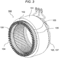
- FIG. 3 is a perspective view illustrating a single body of the stator 100 of the rotary electric machine 1
- FIG. 4 is a cross-sectional view illustrating the inside of each slot 105.
- this stator 100 has a stator core (also referred to as a stator iron core) 101 provided with a plurality of slots 105 in its inner circumference side and three stator coils 102 wound around the stator core 101 corresponding a U-phase, a V-phase, and a W-phase.
- the slots 105 are formed to penetrate in the axial direction and are arranged with equal intervals in the circumferential direction at a predetermined circumferential pitch.
- slits 108 extending in the axial direction are formed in the inner circumference side.
- each stator coil 102 is formed as a rectangular conductor provided with an insulation coating 110, and a plurality of conductors 106 are inserted into and held by the slots 105 as described below.
- the neighboring conductors 106 inside the same slot 105 are welded to each other in welding portions 104 provided in one end side (lower end side of FIG. 3 ) of the stator core 101, so as to form a long stator coil 102 where a plurality of conductors 106 are electrically connected in the welding portions 104.
- a part of this conductor 106 in the bonding target portion side protrudes to the outside in the axial direction of the slot 105, and the insulation coating is stripped off across the entire circumference of the bonding target portion 104.
- An insulation paper 103 is inserted into each slot 105, so that a straight portion 109 of the conductor 106 inserted into the inside of the slot 105 and the stator core 101 are insulated from each other by this insulation paper 103.
- the insulation paper 103 is provided to bind two neighboring conductors 106 out of four conductors 106 arranged in each slot 105. That is, two insulation papers 103 are provided in each slot 105.
- Each stator coil 102 extends across a plurality of slots 105 separated with a predetermined circumferential pitch by the extracted wire portion 107 that is extracted from one end of the axial direction of the slot 105 and has an approximately U-shape or V-shape.
- the stator coils 102 intersect each other and are disposed to neighbor each other while a portion 111 where the insulation coating 110 is removed is erected.
- a plurality of stator coils 102 generate a plurality of magnetic poles arranged to form polarities alternating in the rotational direction.
- conductors 106A, 106B, 106C, and 106D inserted into the slot 105 are arranged in a line in the radial direction of the stator core 101 so as to form concentric layers.
- the conductors 106A, 106B, 106C, and 106D inserted to each slot 105 are defined as first, second, third, and fourth layers in order from the inner diameter direction. That is, the conductor portion 106A is disposed in the first layer, the conductor portion 106B is disposed in the second layer, the conductor portion 106C is disposed in the third layer, and the conductor portion 106D is disposed in the fourth layer.
- FIG. 5 is a diagram illustrating a state that the coil is inserted into the stator core as seen from the inner diameter side.
- Each conductor 106 of the stator coil 102 is a rectangular cross-sectional coil as illustrated in FIGS. 4 and 5 .
- the stator coil is formed of oxygen-free copper or oxygen-containing copper.
- the level of oxygen is set to approximately 10 ppm or higher and approximately 1000 ppm or lower.
- Each conductor 106 has a straight portion 110 penetrating through the slot 105 in the axial direction, and one of the extracted wire portions 107 extracted from one end (right end in FIG. 3 ) in the axial direction of the slot 105 is formed in a U-shape or a V-shape.
- each conductor 106 has the bonding portions 104 in both ends.
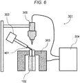
- a bonding member feeder 302 for supplying the bonding member 401 to the bonding target portion 104 is operated in synchronization with a gas arc welder 301 to bond the bonding target portions 104.
- the bonding target portions 104 of the stator coils 102 are pressed by a bonding target portion gripper 303, and an electric current then flows between the bonding target portions 104 of the stator coils 102 through a welding power source 304 and an electrode 305, so that the bonding member 401 supplied from the bonding member feeder 302 and the stator coil 102 are heated and melted by arc.
- the electrode 305 is preferably formed of a tungsten (W)-based or molybdenum (Mo)-based material.
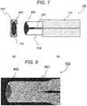
- a bonding member 401 having a melting point lower than that of the bonding target portion is interposed between the bonding target portions of the stator coils 102.
- the stator coil bonding portion 104 is melted such that a tip of the bonding portion becomes an alloy layer 402 between the stator coil conductor 102 and the bonding member 401, and a root of the bonding portion is electrically bonded through brazing of the bonding member 401.
- a shape of the tip of the bonding portion as seen in a top view since a melting area of the bonding target portion 104 is small, a part of the end surface forms an angled portion 501. Therefore, it is possible to secure a distance from the neighboring bonding portion 104 and improve insulation reliability.
- a cross-sectional shape after the bonding is characterized in that a portion (alloy layer) 402 formed of an alloy of the stator coil conductor 102 and the bonding member 401 at the tip of the bonding portion is formed in an approximately T-shape. Since the alloy layer 402 having an approximately T-shaped cross section and the root of the bonding portion are electrically bonded through brazing of the bonding member, the heat amount applied to the bonding target portion 104 can be halved, compared to the arc bonding method of the background art.
- FIG. 9(a) is a top view illustrating a bonding portion as seen from a coil end surface side
- FIG. 9(b) is a cross-sectional view illustrating the bonding portion of the coil taken along the axial direction.
- the stator coil 102 is formed as a rectangular conductor provided with an insulation coating 110, and the insulation coating 401 is removed at the bonding target portion 104.
- This embodiment is different from the first embodiment in that the melting amount of the bonding target portion 104 increases, and the area of the alloy layer 402 increases, so that the shape of the coil tip become circular as seen from the top.
- the shape of the coil tip is circular, it is possible to alleviate stress concentration on the bonding portion 104 while obtaining the same effects as those of the first embodiment in which the alloy layer 402 has an approximately T-shaped cross section.
- the bonding may be similarly performed by employing an electron beam instead of the arc as a heat source to melt the bonding member 401 and the stator coil 102.
- the bonding may also be performed similarly through laser welding, plasma welding, gas welding, metal inert gas (MIG) welding, and the like.
- FIGS. 10(a) and 10(b) illustrate a third bonding example between the stator coil 102 and the bonding member 401.
- FIG. 10(a) is a top view illustrating the bonding portion as seen from the coil end surface side
- FIG. 10(b) is a cross-sectional view illustrating the bonding portion of the coil taken along the axial direction.
- the conductors of the stator coils 102 have a circular cross-sectional shape. Components of each conductor, and the configuration, the bonding method, and the effects of the bonding member 401 are similar to those of the first and second embodiments.
- FIGS. 11(a) and 11(b) illustrate a fourth bonding example between the stator coil 102 and the bonding member 401.
- FIG. 11 (a) is a top view illustrating the bonding portion as seen from the coil end surface side
- FIG. 11 (b) is a cross-sectional view illustrating the bonding portion of the coil taken along the axial direction.
- a bundle of wires obtained by collecting a plurality of conductors are used in the stator coil 102.
- Components of each conductor, and the configuration, the bonding method, and the effects of the bonding member 401 are similar to those of the first to third embodiments.
- This embodiment is different from the first to third embodiments in that the bonding target portions are formed across a plurality of conductors, and thus, the cross section of the bonded alloy layer 403 has an approximately comb tooth shape. Since the alloy layer 403 has a comb tooth shape, it is possible to increase a contact area with the bonding target portion and secure a sufficient bonding strength.
- FIGS. 12(a) and 12(b) illustrate a fifth bonding example between the stator coil 102 and the bonding member 401.
- FIG. 12 (a) is a top view illustrating the bonding portion as seen from the coil end surface side
- FIG. 12 (b) is a cross-sectional view illustrating the bonding portion of the coil taken along the axial direction.
- stator coil 102 serving as the bonding target portion may be any other cross-sectional shape such as rectangular, circular, or polygonal shapes without a limitation.
- This embodiment is different from the first to third embodiments in that three or more stator coils 102 disposed in the outer diameter direction of the stator are bonded. Components of each conductor, and the configuration, the bonding method, and the effects of the bonding member 401 are similar to those of the fourth embodiment.
- FIGS. 13(a) and 13(b) illustrate a sixth bonding example between the stator coil 102 and the bonding member 401.
- FIG. 13(a) is a top view illustrating the bonding portion as seen from the coil end surface side
- FIG. 13(b) is a cross-sectional view illustrating the bonding portion of the coil taken along the axial direction.
- one of the stator coils 102 of the conductor serving as the bonding target portion has a rectangular cross-sectional shape
- the other stator coil 102 has a circular cross-sectional shape.
- any other shapes may also be employed.
- the bonding target portion may have, for example, rectangular, circular, or polygonal shapes. Components of each conductor, and the configuration, the bonding method, and the effects of the bonding member 401 are similar to those of the first to third embodiments.
- a bonding area through brazing can be secured using an approximately T-shaped alloy layer 402 even when the bonding target conductors have different cross-sectional shapes. Therefore, it is possible to improve electric resistance while improving the bonding strength.
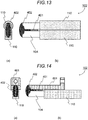
- FIGS. 14(a) and 14(b) illustrate a seventh bonding example between the stator coil 102 and the bonding member 401.
- FIG. 14 (a) is a top view illustrating the bonding portion as seen from the coil end surface side
- FIG. 14 (b) is a cross-sectional view illustrating the bonding portion of the coil taken along the axial direction.
- the stator coil 102 and a flat-plate-shaped conductor 601 for connection to an external power source for example, copper terminal
- an external power source for example, copper terminal
- the bonding portion of the conductor serving as the stator coil of the rotary electric machine it is possible to bond the conductors with a sufficient bonding strength while suppressing a heat amount applied to the base material of the conductor to the minimum.
- it is possible to reduce a damage to the insulation coating of the coil segment caused by the heat input from the outside it is possible to lower the height of the coil end and improve electric resistance.
- the present invention is not limited to the embodiments described above, and may include various modifications.
- the aforementioned embodiments have been described in details for illustrative purposes, the present invention is not necessarily limited to a case where all of the aforementioned configurations are provided.
- a part of the configuration of a certain embodiment may be substitute with any configuration of other embodiments, and a configuration of one embodiment may be added to any configuration of other embodiments.
- various other additions, deletions, or substitutions may also be possible.
Landscapes
- Engineering & Computer Science (AREA)
- Power Engineering (AREA)
- Manufacturing & Machinery (AREA)
- Windings For Motors And Generators (AREA)
- Manufacture Of Motors, Generators (AREA)
- Insulation, Fastening Of Motor, Generator Windings (AREA)
Abstract
Description
- The present invention relates to a rotary-electric-machine stator coil, a rotary-electric-machine stator having the same, and a rotary electric machine having the same.
- As a background art of this technical field, there is known
JP 2009-81980 A - PTL 1: Japanese Patent Application Laid-Open No.
2009-81980 - If conductors of coil segments are bonded to each other through TIG welding, the heat input for melting and bonding a base material easily increases, and an insulation coating on the coil conductor surface is easily damaged. As a countermeasure, as discussed in
PTL 1, a spacer applied with a bonding member having a low melting point in advance is inserted between both surfaces for providing a gap between the bonding conductors, and the spacer is melted and bonded through TIG welding, so that a damage to the insulation coating is suppressed. In this technique, an alloy layer is necessary because a bonding strength between the bonding conductors is insufficient. - In this regard, an object of the present invention is to propose a conductor bonding method capable of substituting with the background art described above and provide a rotary-electric-machine stator coil, a rotary-electric-machine stator having the same, and a rotary electric machine having the same, capable of improving a bonding strength and insulation reliability in the conductor bonding portion.
- In order to address the aforementioned problems, for example, the configurations described in claims are employed.
- The present application includes a plurality of means to solve the above issue, and an example thereof includes: a conductor having a bonding portion bonded to other conductors; and a bonding member having a melting point lower than a melting point of the conductor, wherein a tip of the bonding portion has an alloy layer formed of an alloy of the conductor and the bonding member, and a root of the bonding portion is electrically connected by the bonding member.
- According to the present invention, it is possible to provide a rotary-electric-machine stator coil, a rotary-electric-machine stator having the same, and a rotary electric machine having the same, capable of improving a bonding strength and insulation reliability in the conductor bonding portion.
- Other object, configurations, and effects will become apparent by reading the following description of the embodiments.
-
- [
FIG. 1] FIG. 1 is a block diagram illustrating a hybrid electric vehicle. - [
FIG. 2] FIG. 2 is a cross-sectional view illustrating a rotary electric machine according to an embodiment of the present invention. - [
FIG. 3] FIG. 3 is an exterior view illustrating a rotary-electric-machine stator. - [
FIG. 4] FIG. 4 is a diagram schematically illustrating a coil inserted into a single slot. - [
FIG. 5] FIG. 5 is a diagram illustrating a state that the coil is inserted into the stator core as seen from an inner diameter side. - [
FIG. 6] FIG. 6 is a diagram illustrating a bonding method using an arc welder according to a first embodiment. - [
FIGS. 7(a) and 7(b)] FIGS. 7(a) and 7(b) are diagrams illustrating a bonding example between a stator coil conductor using a rectangular conductor and a bonding member, in whichFIG. 7(a) is a top view illustrating a bonding portion as seen in a coil end surface side, andFIG. 7(b) is a cross-sectional view illustrating a bonding portion of the coil taken along an axial direction. - [
FIG. 8] FIG. 8 is a photograph taken to show a cross section obtained by applying the first embodiment. - [
FIGS. 9(a) and 9(b)] FIGS. 9(a) and 9(b) are diagrams illustrating a second bonding example between a stator coil conductor using a rectangular conductor and a bonding member, in whichFIG. 9 (a) is a top view illustrating the bonding portion as seen in the coil end surface side, andFIG. 9(b) is a cross-sectional view illustrating the bonding portion of the coil taken along the axial direction. - [
FIGS. 10(a) and 10(b)] FIGS. 10 (a) and 10 (b) are diagrams illustrating a third bonding example between a stator coil conductor using a round wire and the bonding member, in whichFIG. 10(a) is a top view illustrating the bonding portion as seen in the coil end surface side, andFIG. 10(b) is a cross-sectional view illustrating the bonding portion of the coil taken along the axial direction. - [
FIGS. 11 (a) and 11(b)] FIGS. 11 (a) and 11 (b) are diagrams illustrating the second bonding example between a stator coil conductor using a wire obtained by collecting a plurality of conductors (for example, a bundle of wires) and the bonding member, in whichFIG. 11 (a) is a top view illustrating the bonding portion as seen in the coil end surface side, andFIG. 11(b) is a cross-sectional view illustrating the bonding portion of the coil taken along the axial direction. - [
FIGS. 12(a) and 12(b)] FIGS. 12(a) and 12(b) are diagrams illustrating a bonding example between three or more stator coil conductors and the bonding member, in whichFIG. 12(a) is a top view illustrating the bonding portion as seen in the coil end surface side, andFIG. 12(b) is a cross-sectional view illustrating the bonding portion of the coil taken along the axial direction. - [
FIGS. 13(a) and 13(b)] FIGS. 13(a) and 13(b) are diagrams illustrating a sixth bonding example between the stator coil conductor and the bonding member, in whichFIG. 13(a) is a top view illustrating the bonding portion as seen in the coil end surface side, andFIG. 13 (b) is a cross-sectional view illustrating the bonding portion of the coil taken along the axial direction. - [
FIGS. 14(a) and 14(b)] FIGS. 14(a) and 14(b) are diagrams illustrating a bonding example between the stator coil conductor, an external power connection conductor, and the bonding member, in whichFIG. 14 (a) is a top view illustrating the bonding portion as seen in the coil end surface side, andFIG. 14(b) is a cross-sectional view illustrating the bonding portion of the coil taken along the axial direction. - Embodiments of the present invention will now be described with reference to the accompanying drawings.
- In the following description, a rotary electric machine for a hybrid electric vehicle will be described as an example of the rotary electric machine. In addition, in the following description, an "axial direction" refers to a direction along a rotational axis of the rotary electric machine. A "circumferential direction" refers to a direction along a rotational direction of the rotary electric machine. A "radial direction" refers to a radius vector direction (radius direction) with respect to a rotational center of the rotary electric machine.
- The embodiments described herein relate to a coil structure of a stator of the rotary electric machine. The rotary electric machine can be roughly divided into a cylindrical stator and a rotor disposed in an inner circumference side of the stator by interposing a predetermined gap.
- The stator has a plurality of magnetic poles arranged such that their polarities are alternately changed along the rotational direction and includes a cylindrical stator core and a plurality of stator coils wound around the stator core. The stator core is provided with a plurality of slots that penetrate in the axial direction and are arranged along a circumferential direction to store the stator coil. While each stator coil extends in the axial direction inside each slot, the stator coil extends across a plurality of slots separated by an extracted wire portion extracted from one end of the axial direction of the slot with a predetermined circumferential pitch to match a plurality of magnetic poles. Each stator coil electrically bonds a plurality of conductors stored and disposed inside each slot using a bonding member having a melting point lower than that of the coil conductor. A tip of the bonding portion of the bonded coil conductor is formed of an alloy layer of the coil conductor and the bonding member, and a root of the bonding portion between the coil conductors is electrically connected by the bonding member.
- According to the present invention, due to the alloy layer of the coil conductor and the bonding member having a melting point lower than that of the coil conductor, and bonding of the coil conductor through brazing using the bonding member, influence of a heat input from the outside of the coil conductor is minimized. Therefore, it is possible to shorten the coil end by reducing a strip length of the insulation coating of the coil relative to the background art while satisfying a dielectric strength, and secure a sufficient gap from other components such as a transmission unit.
-
FIG. 1 is a block diagram illustrating a hybrid electric vehicle mounted with a rotary electric machine according to an embodiment of the present invention. Anengine 2 and a rotaryelectric machine 3 as a vehicle power source are mounted on thevehicle 1. Note that two rotary electric machines having different roles may also be used together. In this case, one of the rotary electric machines performs both electricity generation and vehicle driving operation, and the other rotary electric machine performs vehicle driving operation. - A rotation torque caused by the
engine 2 and the rotaryelectric machine 3 is transmitted to vehicle wheels (driving wheels) 6 through atransmission unit 4 such as a continuously variable transmission or a stepped-speed automatic transmission and adifferential gear 5. The rotaryelectric machine 3 is mounted between theengine 2 and thetransmission unit 4 or in thetransmission unit 4. Therefore, the rotaryelectric machine 3 is required to have a small size and output high power in order to minimize an influence on the space of thevehicle 1. -
FIG. 2 is a partial cross-sectional view schematically illustrating the rotaryelectric machine 3. InFIG. 2 , the left side with respect to theshaft 201 is illustrated as a cross-sectional view, and the right side is illustrated as a side view. The rotaryelectric machine 3 is housed in acasing 7. Here, if the rotaryelectric machine 3 is interposed between theengine 2 and thetransmission unit 4 as illustrated inFIG. 1 , thecasing 7 may be incorporated into a casing of theengine 2 or a casing of thetransmission unit 4. In addition, if the rotaryelectric machine 3 is mounted on thetransmission unit 4, thecasing 7 is incorporated into the casing of thetransmission unit 4. - The rotary
electric machine 3 has astator 100 and arotor 200. Therotor 200 is disposed in the inner circumference side of thestator 100 with agap 11. Therotor 200 is fixed to theshaft 201 and is rotated in synchronization with theshaft 201. Both ends of theshaft 201 are rotatably supported by thecasing 7 by interposingbearings stator 100 is fixed to the inner circumference side of thecasing 7 using abolt 12 and the like. This rotaryelectric machine 3 is a three-phase synchronous type motor provided with a permanent magnet in therotor 200 and is operated as a motor by supplying a large three-phase AC current (for example, approximately 300 A) to thestator 100. -
FIG. 3 is a perspective view illustrating a single body of thestator 100 of the rotaryelectric machine 1, andFIG. 4 is a cross-sectional view illustrating the inside of eachslot 105. - As illustrated in
FIGS. 3 and4 , thisstator 100 has a stator core (also referred to as a stator iron core) 101 provided with a plurality ofslots 105 in its inner circumference side and threestator coils 102 wound around thestator core 101 corresponding a U-phase, a V-phase, and a W-phase. Theslots 105 are formed to penetrate in the axial direction and are arranged with equal intervals in the circumferential direction at a predetermined circumferential pitch. In addition, slits 108 extending in the axial direction are formed in the inner circumference side. - According to this embodiment, each
stator coil 102 is formed as a rectangular conductor provided with aninsulation coating 110, and a plurality ofconductors 106 are inserted into and held by theslots 105 as described below. In addition, the neighboringconductors 106 inside thesame slot 105 are welded to each other inwelding portions 104 provided in one end side (lower end side ofFIG. 3 ) of thestator core 101, so as to form along stator coil 102 where a plurality ofconductors 106 are electrically connected in thewelding portions 104. A part of thisconductor 106 in the bonding target portion side protrudes to the outside in the axial direction of theslot 105, and the insulation coating is stripped off across the entire circumference of thebonding target portion 104. Aninsulation paper 103 is inserted into eachslot 105, so that astraight portion 109 of theconductor 106 inserted into the inside of theslot 105 and thestator core 101 are insulated from each other by thisinsulation paper 103. As illustrated inFIG. 4 , theinsulation paper 103 is provided to bind two neighboringconductors 106 out of fourconductors 106 arranged in eachslot 105. That is, twoinsulation papers 103 are provided in eachslot 105. - Each
stator coil 102 extends across a plurality ofslots 105 separated with a predetermined circumferential pitch by the extractedwire portion 107 that is extracted from one end of the axial direction of theslot 105 and has an approximately U-shape or V-shape. The stator coils 102 intersect each other and are disposed to neighbor each other while aportion 111 where theinsulation coating 110 is removed is erected. In addition, a plurality of stator coils 102 generate a plurality of magnetic poles arranged to form polarities alternating in the rotational direction. - As illustrated in
FIG. 4 , fourconductors slot 105 are arranged in a line in the radial direction of thestator core 101 so as to form concentric layers. Theconductors slot 105 are defined as first, second, third, and fourth layers in order from the inner diameter direction. That is, theconductor portion 106A is disposed in the first layer, theconductor portion 106B is disposed in the second layer, theconductor portion 106C is disposed in the third layer, and theconductor portion 106D is disposed in the fourth layer. -
FIG. 5 is a diagram illustrating a state that the coil is inserted into the stator core as seen from the inner diameter side. - Each
conductor 106 of thestator coil 102 is a rectangular cross-sectional coil as illustrated inFIGS. 4 and5 . The stator coil is formed of oxygen-free copper or oxygen-containing copper. For example, in the case of the oxygen-containing copper, the level of oxygen is set to approximately 10 ppm or higher and approximately 1000 ppm or lower. Eachconductor 106 has astraight portion 110 penetrating through theslot 105 in the axial direction, and one of the extractedwire portions 107 extracted from one end (right end inFIG. 3 ) in the axial direction of theslot 105 is formed in a U-shape or a V-shape. In addition, eachconductor 106 has thebonding portions 104 in both ends. - As illustrated in
FIG. 6 , in a bonding process according to the present invention, abonding member feeder 302 for supplying thebonding member 401 to thebonding target portion 104 is operated in synchronization with agas arc welder 301 to bond thebonding target portions 104. In the bonding, thebonding target portions 104 of the stator coils 102 are pressed by a bondingtarget portion gripper 303, and an electric current then flows between thebonding target portions 104 of the stator coils 102 through awelding power source 304 and anelectrode 305, so that thebonding member 401 supplied from thebonding member feeder 302 and thestator coil 102 are heated and melted by arc. In this case, theelectrode 305 is preferably formed of a tungsten (W)-based or molybdenum (Mo)-based material. - As illustrated in
FIGS. 7(a), 7(b), and 8 , abonding member 401 having a melting point lower than that of the bonding target portion is interposed between the bonding target portions of the stator coils 102. The statorcoil bonding portion 104 is melted such that a tip of the bonding portion becomes analloy layer 402 between thestator coil conductor 102 and thebonding member 401, and a root of the bonding portion is electrically bonded through brazing of thebonding member 401. In a shape of the tip of the bonding portion as seen in a top view, since a melting area of thebonding target portion 104 is small, a part of the end surface forms anangled portion 501. Therefore, it is possible to secure a distance from the neighboringbonding portion 104 and improve insulation reliability. - As illustrated in
FIG. 7(b) , a cross-sectional shape after the bonding is characterized in that a portion (alloy layer) 402 formed of an alloy of thestator coil conductor 102 and thebonding member 401 at the tip of the bonding portion is formed in an approximately T-shape. Since thealloy layer 402 having an approximately T-shaped cross section and the root of the bonding portion are electrically bonded through brazing of the bonding member, the heat amount applied to thebonding target portion 104 can be halved, compared to the arc bonding method of the background art. - Using the bonding method described above, it is possible to shorten the strip length of the insulation coating for reducing a damage to the
insulation coating 110 in the outer circumference of the stator coil caused by the heat generated during the bonding and lower a height of the coil end while satisfying the bonding strength. - A second bonding example between the
stator coil 102 and thebonding member 401 will be described.FIG. 9(a) is a top view illustrating a bonding portion as seen from a coil end surface side, andFIG. 9(b) is a cross-sectional view illustrating the bonding portion of the coil taken along the axial direction. - Similarly, according to this embodiment, the
stator coil 102 is formed as a rectangular conductor provided with aninsulation coating 110, and theinsulation coating 401 is removed at thebonding target portion 104. This embodiment is different from the first embodiment in that the melting amount of thebonding target portion 104 increases, and the area of thealloy layer 402 increases, so that the shape of the coil tip become circular as seen from the top. - Similarly, in this embodiment, since the shape of the coil tip is circular, it is possible to alleviate stress concentration on the
bonding portion 104 while obtaining the same effects as those of the first embodiment in which thealloy layer 402 has an approximately T-shaped cross section. - Note that the bonding may be similarly performed by employing an electron beam instead of the arc as a heat source to melt the
bonding member 401 and thestator coil 102. In addition, the bonding may also be performed similarly through laser welding, plasma welding, gas welding, metal inert gas (MIG) welding, and the like. -
FIGS. 10(a) and 10(b) illustrate a third bonding example between thestator coil 102 and thebonding member 401.FIG. 10(a) is a top view illustrating the bonding portion as seen from the coil end surface side, andFIG. 10(b) is a cross-sectional view illustrating the bonding portion of the coil taken along the axial direction. - In this embodiment, the conductors of the stator coils 102 have a circular cross-sectional shape. Components of each conductor, and the configuration, the bonding method, and the effects of the
bonding member 401 are similar to those of the first and second embodiments. -
FIGS. 11(a) and 11(b) illustrate a fourth bonding example between thestator coil 102 and thebonding member 401.FIG. 11 (a) is a top view illustrating the bonding portion as seen from the coil end surface side, andFIG. 11 (b) is a cross-sectional view illustrating the bonding portion of the coil taken along the axial direction. - In this embodiment, for example, a bundle of wires obtained by collecting a plurality of conductors are used in the
stator coil 102. Components of each conductor, and the configuration, the bonding method, and the effects of thebonding member 401 are similar to those of the first to third embodiments. This embodiment is different from the first to third embodiments in that the bonding target portions are formed across a plurality of conductors, and thus, the cross section of the bondedalloy layer 403 has an approximately comb tooth shape. Since thealloy layer 403 has a comb tooth shape, it is possible to increase a contact area with the bonding target portion and secure a sufficient bonding strength. -
FIGS. 12(a) and 12(b) illustrate a fifth bonding example between thestator coil 102 and thebonding member 401.FIG. 12 (a) is a top view illustrating the bonding portion as seen from the coil end surface side, andFIG. 12 (b) is a cross-sectional view illustrating the bonding portion of the coil taken along the axial direction. - In
FIGS. 12(a) and 12(b) , a conductor having a rectangular cross-sectional shape is employed. However, thestator coil 102 serving as the bonding target portion may be any other cross-sectional shape such as rectangular, circular, or polygonal shapes without a limitation. - This embodiment is different from the first to third embodiments in that three or more stator coils 102 disposed in the outer diameter direction of the stator are bonded. Components of each conductor, and the configuration, the bonding method, and the effects of the
bonding member 401 are similar to those of the fourth embodiment. - According to this embodiment, even when three or more bonding target conductors are employed, it is possible to bond them simultaneously. Therefore, it is possible to reduce a work load in the bonding without degrading the bonding strength.
-
FIGS. 13(a) and 13(b) illustrate a sixth bonding example between thestator coil 102 and thebonding member 401.FIG. 13(a) is a top view illustrating the bonding portion as seen from the coil end surface side, andFIG. 13(b) is a cross-sectional view illustrating the bonding portion of the coil taken along the axial direction. - In
FIGS. 13(a) and 13(b) , one of the stator coils 102 of the conductor serving as the bonding target portion has a rectangular cross-sectional shape, and theother stator coil 102 has a circular cross-sectional shape. Without limiting to a combination of two or more shapes of the bonding target portions, any other shapes may also be employed. For example, the bonding target portion may have, for example, rectangular, circular, or polygonal shapes. Components of each conductor, and the configuration, the bonding method, and the effects of thebonding member 401 are similar to those of the first to third embodiments. - According to this embodiment, a bonding area through brazing can be secured using an approximately T-shaped
alloy layer 402 even when the bonding target conductors have different cross-sectional shapes. Therefore, it is possible to improve electric resistance while improving the bonding strength. -
FIGS. 14(a) and 14(b) illustrate a seventh bonding example between thestator coil 102 and thebonding member 401.FIG. 14 (a) is a top view illustrating the bonding portion as seen from the coil end surface side, andFIG. 14 (b) is a cross-sectional view illustrating the bonding portion of the coil taken along the axial direction. In this embodiment, thestator coil 102 and a flat-plate-shapedconductor 601 for connection to an external power source (for example, copper terminal) are employed. Since an approximately T-shapedalloy layer 402 is provided, components of each conductor, and the configuration, the bonding method, and the effects of thebonding member 401 are similar to those of the sixth embodiment. - As described above, according to the present invention, in the bonding portion of the conductor serving as the stator coil of the rotary electric machine, it is possible to bond the conductors with a sufficient bonding strength while suppressing a heat amount applied to the base material of the conductor to the minimum. In addition, since it is possible to reduce a damage to the insulation coating of the coil segment caused by the heat input from the outside, it is possible to lower the height of the coil end and improve electric resistance.
- Note that the present invention is not limited to the embodiments described above, and may include various modifications. For example, while the aforementioned embodiments have been described in details for illustrative purposes, the present invention is not necessarily limited to a case where all of the aforementioned configurations are provided. In addition, a part of the configuration of a certain embodiment may be substitute with any configuration of other embodiments, and a configuration of one embodiment may be added to any configuration of other embodiments. Furthermore, for a part of the configuration of each embodiment, various other additions, deletions, or substitutions may also be possible.
-
- 1 vehicle
- 2 engine
- 3 rotary electric machine
- 4 transmission unit
- 5 differential gear
- 6 vehicle wheel
- 7 casing
- 100 stator
- 101 stator core
- 102 conductor
- 103 insulation paper
- 104 conductor welding portion
- 105 slot
- 106a to 106d coil conductor portion
- 107 extracted portion of conductor formed in U-shape or V-shape
- 108 slit provided slot
- 109 conductor straight portion in slot
- 110 insulation coating of conductor
- 111 strip portion of insulation coating of conductor
- 200 rotor
- 201 shaft
- 202A, 202B bearing
- 301 gas arc welder
- 302 bonding member feeder
- 303 bonding target portion gripper
- 304 welding power source
- 305 welding electrode
- 401 bonding member
- 402 T-shaped alloy layer of bonding member and conductor
- 403 comb-tooth-shaped alloy layer of bonding member and conductor
- 501 angled portion of conductor after welding
- 601 flat-plate-shaped conductor for connection to external power source
Claims (10)
- A rotary-electric-machine stator coil comprising:a conductor having a bonding portion bonded to other conductors; anda bonding member having a melting point lower than a melting point of the conductor,wherein a tip of the bonding portion has an alloy layer formed of an alloy of the conductor and the bonding member, anda root of the bonding portion is electrically connected by the bonding member.
- The rotary-electric-machine stator coil according to claim 1, wherein the alloy layer has an approximately T-shape.
- The rotary-electric-machine stator coil according to claim 1, wherein the alloy layer is formed by collectively bonding tips of three or more bonding portions and has an approximately comb tooth shape.
- The rotary-electric-machine stator coil according to any one of claims 1 to 3, wherein the conductor is formed of oxygen-free copper or oxygen-containing copper.
- The rotary-electric-machine stator coil according to any one of claims 1 to 4, wherein an angled portion or a spherical portion is provided in the tip of the bonding portion.
- The rotary-electric-machine stator coil according to any one of claims 1 to 5, wherein a cross-sectional shape of the conductor is rectangular or circular.
- The rotary-electric-machine stator coil according to any one of claims 1 to 6, wherein a bonding member having a melting point lower than a melting point of a conductor bonding target portion is provided between the stator coil serving as the conductor bonding target portion and a conductor for connection to an external power source,
a tip of the conductor bonding target portion and a tip of the conductor for connection to the external power source are formed of an alloy of the conductor of the conductor bonding target portion and the tip of the conductor for connection between the bonding member and the external power source, and
a root of the conductor bonding target portion and a root of the conductor for connection to the external power source are electrically connected by the bonding member. - A rotary-electric-machine stator comprising:the rotary-electric-machine stator coil according to any one of claims 1 to 7; anda stator core,wherein the conductor is continuously wound around the entire circumference of the stator core to form the stator coil.
- A rotary electric machine comprising:the rotary-electric-machine stator according to claim 8; anda rotor.
- A method of manufacturing a rotary-electric-machine stator coil formed by bonding a plurality of conductors using a bonding portion, the method comprising:supplying a bonding member having a melting point lower than a melting point of the conductor to the bonding portion; andmelting the bonding member and the conductor by electrically conducting the bonding portions to form an alloy layer,wherein the alloy layer is formed in a tip of the bonding portion, anda root of the bonding portion is electrically bonded using the bonding member.
Applications Claiming Priority (2)
| Application Number | Priority Date | Filing Date | Title |
|---|---|---|---|
| JP2014263810 | 2014-12-26 | ||
| PCT/JP2015/082330 WO2016103989A1 (en) | 2014-12-26 | 2015-11-18 | Rotating-electric-machine stator coil, rotating-electric-machine stator provided with said coil, and rotating electric machine provided with said stator |
Publications (3)
| Publication Number | Publication Date |
|---|---|
| EP3240147A1 true EP3240147A1 (en) | 2017-11-01 |
| EP3240147A4 EP3240147A4 (en) | 2018-08-15 |
| EP3240147B1 EP3240147B1 (en) | 2022-08-10 |
Family
ID=56150022
Family Applications (1)
| Application Number | Title | Priority Date | Filing Date |
|---|---|---|---|
| EP15872558.0A Active EP3240147B1 (en) | 2014-12-26 | 2015-11-18 | Method of manufacturing a rotary-electric-machine stator coil |
Country Status (5)
| Country | Link |
|---|---|
| US (1) | US11088583B2 (en) |
| EP (1) | EP3240147B1 (en) |
| JP (1) | JP6448664B2 (en) |
| CN (1) | CN107005116B (en) |
| WO (1) | WO2016103989A1 (en) |
Cited By (3)
| Publication number | Priority date | Publication date | Assignee | Title |
|---|---|---|---|---|
| CN107005116A (en) * | 2014-12-26 | 2017-08-01 | 日立汽车系统株式会社 | Stator coil of rotating electric machine, stator of rotating electric machine having the coil, and rotating electric machine having the stator |
| CN112335157A (en) * | 2018-09-10 | 2021-02-05 | 日立汽车系统株式会社 | Stator of rotating electric machine and rotating electric machine having the same |
| US11777382B2 (en) | 2017-07-27 | 2023-10-03 | Strama-Mps Maschinenbau Gmbh & Co. Kg | Method and device for processing conductor segments of a winding support of an electric machine |
Families Citing this family (22)
| Publication number | Priority date | Publication date | Assignee | Title |
|---|---|---|---|---|
| CN108141083B (en) * | 2015-09-25 | 2020-04-21 | 日立汽车系统株式会社 | Rotary electric machine and method of making the same |
| JP6642123B2 (en) * | 2016-03-04 | 2020-02-05 | 株式会社デンソー | Rotating electric machine |
| JP2019118159A (en) * | 2017-12-26 | 2019-07-18 | トヨタ自動車株式会社 | Welding method for segment conductor |
| GB2570927B (en) * | 2018-02-12 | 2023-05-31 | Epropelled Ltd | Electromagnetic devices |
| EP3780014A4 (en) * | 2018-03-30 | 2021-12-29 | Furukawa Electric Co., Ltd. | Insulated electric wire material, method for manufacturing insulated electric wire material, coil, and electric/electronic device |
| KR20190139864A (en) * | 2018-03-30 | 2019-12-18 | 후루카와 덴키 고교 가부시키가이샤 | Insulated wire material and manufacturing method thereof, coil and electric / electronic device |
| US11374463B2 (en) * | 2018-07-12 | 2022-06-28 | Hitachi Astemo, Ltd. | Stator for rotating electrical machine, rotating electrical machine and method of producing stator for rotating electrical machine |
| JP7061194B2 (en) * | 2018-08-09 | 2022-04-27 | 日立Astemo株式会社 | Stator of rotary electric machine and its manufacturing method |
| JP6846391B2 (en) * | 2018-09-12 | 2021-03-24 | 本田技研工業株式会社 | Wire segment and stator |
| JP2020102981A (en) * | 2018-12-25 | 2020-07-02 | トヨタ自動車株式会社 | Stator for rotary electric machine and manufacturing method therefor |
| JP7131373B2 (en) * | 2018-12-26 | 2022-09-06 | トヨタ自動車株式会社 | Coil wire welding method |
| JP6752323B1 (en) * | 2019-04-10 | 2020-09-09 | 三菱電機株式会社 | Stator winding of rotary electric machine and its manufacturing method |
| JP7541223B2 (en) * | 2019-06-10 | 2024-08-28 | ダイキン工業株式会社 | Rotating electric machine and method of manufacturing same |
| DE102019119666A1 (en) * | 2019-07-19 | 2021-01-21 | Gehring E-Tech Gmbh | Method for welding conductor pieces in a component of an electromechanical transducer and component of an electromechanical transducer with welded conductor pieces |
| US12301075B2 (en) * | 2019-11-20 | 2025-05-13 | Hitachi Astemo, Ltd. | Method for manufacturing stator of rotating electrical machine, stator of rotating electrical machine, and rotating electrical machine |
| FR3105640B1 (en) | 2019-12-20 | 2021-12-03 | Valeo Equip Electr Moteur | electrical conductor for a coiled part of a rotating electrical machine |
| DE102020208921A1 (en) * | 2020-07-16 | 2022-01-20 | Robert Bosch Gesellschaft mit beschränkter Haftung | Stator of an electrical machine |
| CN112803687B (en) * | 2021-02-18 | 2022-05-13 | 江苏胜牌科技有限公司 | Workbench for inserting insulating paper into stator |
| JP7660016B2 (en) * | 2021-04-02 | 2025-04-10 | 株式会社プロテリアル | Welding method and manufacturing method for rotating electric machine |
| FR3130467A1 (en) * | 2021-12-15 | 2023-06-16 | Thales | Rotor for electrical machines wound in oxidized aluminum strip. |
| JP7601056B2 (en) * | 2022-06-17 | 2024-12-17 | トヨタ自動車株式会社 | Manufacturing method of stator coil |
| JP2024047194A (en) * | 2022-09-26 | 2024-04-05 | 日産自動車株式会社 | Rotating electric machine stator and manufacturing method thereof |
Family Cites Families (12)
| Publication number | Priority date | Publication date | Assignee | Title |
|---|---|---|---|---|
| JP2001231205A (en) * | 2000-02-14 | 2001-08-24 | Mitsubishi Electric Corp | Alternator stator |
| JP2002119003A (en) * | 2000-10-10 | 2002-04-19 | Mitsubishi Electric Corp | Stator of rotating electric machine and method of manufacturing the same |
| JP4497102B2 (en) * | 2006-02-10 | 2010-07-07 | 株式会社デンソー | Rotating electrical machine stator for vehicles |
| DE102006019314A1 (en) | 2006-04-26 | 2007-10-31 | Robert Bosch Gmbh | Stator`s bar winding manufacturing method for e.g. claw pole generator, of motor vehicle, involves forming fusion zone by arrangement of ends of segments at contacting area, and connecting ends in pairs by contactless fusion welding process |
| JPWO2008020471A1 (en) * | 2006-08-15 | 2010-01-07 | 株式会社日立製作所 | Rotating electric machine |
| JP5048438B2 (en) * | 2007-09-27 | 2012-10-17 | 日立オートモティブシステムズ株式会社 | Rotating electric machine and its stator |
| JP2012257366A (en) * | 2011-06-08 | 2012-12-27 | Toyota Motor Corp | Rotary electric machine stator and manufacturing method of the same |
| JP5585657B2 (en) * | 2011-12-28 | 2014-09-10 | トヨタ自動車株式会社 | Rotating electric machine and stator manufacturing method |
| US8878414B2 (en) * | 2012-08-09 | 2014-11-04 | GM Global Technology Operations LLC | Stator weld joints and methods of forming same |
| JP5860782B2 (en) * | 2012-08-31 | 2016-02-16 | 日立オートモティブシステムズ株式会社 | Rotating electric machine and manufacturing method thereof |
| JP5554383B2 (en) * | 2012-09-11 | 2014-07-23 | 三菱電機株式会社 | Stator for rotating electric machine and method for manufacturing the stator |
| EP3240147B1 (en) * | 2014-12-26 | 2022-08-10 | Hitachi Astemo, Ltd. | Method of manufacturing a rotary-electric-machine stator coil |
-
2015
- 2015-11-18 EP EP15872558.0A patent/EP3240147B1/en active Active
- 2015-11-18 CN CN201580067870.3A patent/CN107005116B/en active Active
- 2015-11-18 US US15/538,063 patent/US11088583B2/en active Active
- 2015-11-18 WO PCT/JP2015/082330 patent/WO2016103989A1/en not_active Ceased
- 2015-11-18 JP JP2016566036A patent/JP6448664B2/en active Active
Cited By (7)
| Publication number | Priority date | Publication date | Assignee | Title |
|---|---|---|---|---|
| CN107005116A (en) * | 2014-12-26 | 2017-08-01 | 日立汽车系统株式会社 | Stator coil of rotating electric machine, stator of rotating electric machine having the coil, and rotating electric machine having the stator |
| CN107005116B (en) * | 2014-12-26 | 2020-01-10 | 日立汽车系统株式会社 | Stator coil for rotating electrical machine, stator for rotating electrical machine having the coil, and rotating electrical machine having the stator |
| US11777382B2 (en) | 2017-07-27 | 2023-10-03 | Strama-Mps Maschinenbau Gmbh & Co. Kg | Method and device for processing conductor segments of a winding support of an electric machine |
| CN112335157A (en) * | 2018-09-10 | 2021-02-05 | 日立汽车系统株式会社 | Stator of rotating electric machine and rotating electric machine having the same |
| EP3829032A4 (en) * | 2018-09-10 | 2022-04-06 | Hitachi Astemo, Ltd. | ROTATING ELECTRIC MACHINE STATOR AND ROTATING ELECTRIC MACHINE COMPRISING SAME STATOR |
| CN112335157B (en) * | 2018-09-10 | 2024-01-05 | 日立安斯泰莫株式会社 | Stator of a rotating electrical machine and a rotating electrical machine having the stator |
| US12062954B2 (en) | 2018-09-10 | 2024-08-13 | Hitachi Astemo, Ltd. | Stator of rotary electric machine and rotary electric machine including stator |
Also Published As
| Publication number | Publication date |
|---|---|
| US11088583B2 (en) | 2021-08-10 |
| CN107005116B (en) | 2020-01-10 |
| US20170346358A1 (en) | 2017-11-30 |
| JP6448664B2 (en) | 2019-01-09 |
| EP3240147B1 (en) | 2022-08-10 |
| JPWO2016103989A1 (en) | 2017-08-31 |
| CN107005116A (en) | 2017-08-01 |
| WO2016103989A1 (en) | 2016-06-30 |
| EP3240147A4 (en) | 2018-08-15 |
Similar Documents
| Publication | Publication Date | Title |
|---|---|---|
| US11088583B2 (en) | Rotary-electric-machine stator coil, rotary-electric-machine stator having the same, and rotary electric machine having the same | |
| JP7160936B2 (en) | Rotating electrical machine stator and rotating electrical machine provided with the stator | |
| US11387698B2 (en) | Rotating-electrical-machine stator, and rotating electrical machine provided with same | |
| JP6259115B2 (en) | Rotating electric machine stator | |
| US10523073B2 (en) | Rotating electric machine and method of manufacturing same | |
| JP6232449B2 (en) | Rotating electric machine | |
| CN110086280B (en) | Stator and rotating electrical machine provided with the same | |
| JP5991261B2 (en) | Manufacturing method of electric motor | |
| CN109478814B (en) | Stator of rotating electric machine and rotating electric machine | |
| JP6011437B2 (en) | Manufacturing method of electric motor | |
| CN106487142B (en) | The wiring units of electric rotating machine | |
| JP6657258B2 (en) | Stator, rotating electric machine | |
| US20220037945A1 (en) | Rotary electric machine stator | |
| JP2014116993A (en) | Rotary electric machine | |
| JP6118610B2 (en) | Junction structure between terminal and conducting wire and joining method between terminal and conducting wire |
Legal Events
| Date | Code | Title | Description |
|---|---|---|---|
| STAA | Information on the status of an ep patent application or granted ep patent |
Free format text: STATUS: THE INTERNATIONAL PUBLICATION HAS BEEN MADE |
|
| PUAI | Public reference made under article 153(3) epc to a published international application that has entered the european phase |
Free format text: ORIGINAL CODE: 0009012 |
|
| STAA | Information on the status of an ep patent application or granted ep patent |
Free format text: STATUS: REQUEST FOR EXAMINATION WAS MADE |
|
| 17P | Request for examination filed |
Effective date: 20170726 |
|
| AK | Designated contracting states |
Kind code of ref document: A1 Designated state(s): AL AT BE BG CH CY CZ DE DK EE ES FI FR GB GR HR HU IE IS IT LI LT LU LV MC MK MT NL NO PL PT RO RS SE SI SK SM TR |
|
| AX | Request for extension of the european patent |
Extension state: BA ME |
|
| DAV | Request for validation of the european patent (deleted) | ||
| DAX | Request for extension of the european patent (deleted) | ||
| REG | Reference to a national code |
Ref country code: DE Ref legal event code: R079 Ref document number: 602015080305 Country of ref document: DE Free format text: PREVIOUS MAIN CLASS: H02K0003280000 Ipc: H02K0003120000 |
|
| A4 | Supplementary search report drawn up and despatched |
Effective date: 20180718 |
|
| RIC1 | Information provided on ipc code assigned before grant |
Ipc: H02K 15/00 20060101ALI20180712BHEP Ipc: H02K 3/12 20060101AFI20180712BHEP |
|
| STAA | Information on the status of an ep patent application or granted ep patent |
Free format text: STATUS: EXAMINATION IS IN PROGRESS |
|
| 17Q | First examination report despatched |
Effective date: 20201209 |
|
| RAP3 | Party data changed (applicant data changed or rights of an application transferred) |
Owner name: HITACHI ASTEMO, LTD. |
|
| GRAP | Despatch of communication of intention to grant a patent |
Free format text: ORIGINAL CODE: EPIDOSNIGR1 |
|
| STAA | Information on the status of an ep patent application or granted ep patent |
Free format text: STATUS: GRANT OF PATENT IS INTENDED |
|
| INTG | Intention to grant announced |
Effective date: 20220329 |
|
| GRAS | Grant fee paid |
Free format text: ORIGINAL CODE: EPIDOSNIGR3 |
|
| GRAA | (expected) grant |
Free format text: ORIGINAL CODE: 0009210 |
|
| STAA | Information on the status of an ep patent application or granted ep patent |
Free format text: STATUS: THE PATENT HAS BEEN GRANTED |
|
| AK | Designated contracting states |
Kind code of ref document: B1 Designated state(s): AL AT BE BG CH CY CZ DE DK EE ES FI FR GB GR HR HU IE IS IT LI LT LU LV MC MK MT NL NO PL PT RO RS SE SI SK SM TR |
|
| RIN1 | Information on inventor provided before grant (corrected) |
Inventor name: YAMAZAKI SHINJI Inventor name: SHIMIZU HISAYA Inventor name: ONOSE SHIN Inventor name: OJIMA KAZUO Inventor name: NAKAYAMA KENICHI Inventor name: FUKUDA TOMOHIRO |
|
| REG | Reference to a national code |
Ref country code: AT Ref legal event code: REF Ref document number: 1511289 Country of ref document: AT Kind code of ref document: T Effective date: 20220815 Ref country code: CH Ref legal event code: EP |
|
| REG | Reference to a national code |
Ref country code: IE Ref legal event code: FG4D |
|
| REG | Reference to a national code |
Ref country code: DE Ref legal event code: R096 Ref document number: 602015080305 Country of ref document: DE |
|
| REG | Reference to a national code |
Ref country code: NL Ref legal event code: MP Effective date: 20220810 |
|
| REG | Reference to a national code |
Ref country code: LT Ref legal event code: MG9D |
|
| PG25 | Lapsed in a contracting state [announced via postgrant information from national office to epo] |
Ref country code: SE Free format text: LAPSE BECAUSE OF FAILURE TO SUBMIT A TRANSLATION OF THE DESCRIPTION OR TO PAY THE FEE WITHIN THE PRESCRIBED TIME-LIMIT Effective date: 20220810 Ref country code: RS Free format text: LAPSE BECAUSE OF FAILURE TO SUBMIT A TRANSLATION OF THE DESCRIPTION OR TO PAY THE FEE WITHIN THE PRESCRIBED TIME-LIMIT Effective date: 20220810 Ref country code: PT Free format text: LAPSE BECAUSE OF FAILURE TO SUBMIT A TRANSLATION OF THE DESCRIPTION OR TO PAY THE FEE WITHIN THE PRESCRIBED TIME-LIMIT Effective date: 20221212 Ref country code: NO Free format text: LAPSE BECAUSE OF FAILURE TO SUBMIT A TRANSLATION OF THE DESCRIPTION OR TO PAY THE FEE WITHIN THE PRESCRIBED TIME-LIMIT Effective date: 20221110 Ref country code: NL Free format text: LAPSE BECAUSE OF FAILURE TO SUBMIT A TRANSLATION OF THE DESCRIPTION OR TO PAY THE FEE WITHIN THE PRESCRIBED TIME-LIMIT Effective date: 20220810 Ref country code: LV Free format text: LAPSE BECAUSE OF FAILURE TO SUBMIT A TRANSLATION OF THE DESCRIPTION OR TO PAY THE FEE WITHIN THE PRESCRIBED TIME-LIMIT Effective date: 20220810 Ref country code: LT Free format text: LAPSE BECAUSE OF FAILURE TO SUBMIT A TRANSLATION OF THE DESCRIPTION OR TO PAY THE FEE WITHIN THE PRESCRIBED TIME-LIMIT Effective date: 20220810 Ref country code: FI Free format text: LAPSE BECAUSE OF FAILURE TO SUBMIT A TRANSLATION OF THE DESCRIPTION OR TO PAY THE FEE WITHIN THE PRESCRIBED TIME-LIMIT Effective date: 20220810 Ref country code: ES Free format text: LAPSE BECAUSE OF FAILURE TO SUBMIT A TRANSLATION OF THE DESCRIPTION OR TO PAY THE FEE WITHIN THE PRESCRIBED TIME-LIMIT Effective date: 20220810 |
|
| REG | Reference to a national code |
Ref country code: AT Ref legal event code: MK05 Ref document number: 1511289 Country of ref document: AT Kind code of ref document: T Effective date: 20220810 |
|
| PG25 | Lapsed in a contracting state [announced via postgrant information from national office to epo] |
Ref country code: PL Free format text: LAPSE BECAUSE OF FAILURE TO SUBMIT A TRANSLATION OF THE DESCRIPTION OR TO PAY THE FEE WITHIN THE PRESCRIBED TIME-LIMIT Effective date: 20220810 Ref country code: IS Free format text: LAPSE BECAUSE OF FAILURE TO SUBMIT A TRANSLATION OF THE DESCRIPTION OR TO PAY THE FEE WITHIN THE PRESCRIBED TIME-LIMIT Effective date: 20221210 Ref country code: HR Free format text: LAPSE BECAUSE OF FAILURE TO SUBMIT A TRANSLATION OF THE DESCRIPTION OR TO PAY THE FEE WITHIN THE PRESCRIBED TIME-LIMIT Effective date: 20220810 Ref country code: GR Free format text: LAPSE BECAUSE OF FAILURE TO SUBMIT A TRANSLATION OF THE DESCRIPTION OR TO PAY THE FEE WITHIN THE PRESCRIBED TIME-LIMIT Effective date: 20221111 |
|
| PG25 | Lapsed in a contracting state [announced via postgrant information from national office to epo] |
Ref country code: SM Free format text: LAPSE BECAUSE OF FAILURE TO SUBMIT A TRANSLATION OF THE DESCRIPTION OR TO PAY THE FEE WITHIN THE PRESCRIBED TIME-LIMIT Effective date: 20220810 Ref country code: RO Free format text: LAPSE BECAUSE OF FAILURE TO SUBMIT A TRANSLATION OF THE DESCRIPTION OR TO PAY THE FEE WITHIN THE PRESCRIBED TIME-LIMIT Effective date: 20220810 Ref country code: DK Free format text: LAPSE BECAUSE OF FAILURE TO SUBMIT A TRANSLATION OF THE DESCRIPTION OR TO PAY THE FEE WITHIN THE PRESCRIBED TIME-LIMIT Effective date: 20220810 Ref country code: CZ Free format text: LAPSE BECAUSE OF FAILURE TO SUBMIT A TRANSLATION OF THE DESCRIPTION OR TO PAY THE FEE WITHIN THE PRESCRIBED TIME-LIMIT Effective date: 20220810 Ref country code: AT Free format text: LAPSE BECAUSE OF FAILURE TO SUBMIT A TRANSLATION OF THE DESCRIPTION OR TO PAY THE FEE WITHIN THE PRESCRIBED TIME-LIMIT Effective date: 20220810 |
|
| REG | Reference to a national code |
Ref country code: DE Ref legal event code: R097 Ref document number: 602015080305 Country of ref document: DE |
|
| PG25 | Lapsed in a contracting state [announced via postgrant information from national office to epo] |
Ref country code: SK Free format text: LAPSE BECAUSE OF FAILURE TO SUBMIT A TRANSLATION OF THE DESCRIPTION OR TO PAY THE FEE WITHIN THE PRESCRIBED TIME-LIMIT Effective date: 20220810 Ref country code: EE Free format text: LAPSE BECAUSE OF FAILURE TO SUBMIT A TRANSLATION OF THE DESCRIPTION OR TO PAY THE FEE WITHIN THE PRESCRIBED TIME-LIMIT Effective date: 20220810 |
|
| PLBE | No opposition filed within time limit |
Free format text: ORIGINAL CODE: 0009261 |
|
| STAA | Information on the status of an ep patent application or granted ep patent |
Free format text: STATUS: NO OPPOSITION FILED WITHIN TIME LIMIT |
|
| PG25 | Lapsed in a contracting state [announced via postgrant information from national office to epo] |
Ref country code: MC Free format text: LAPSE BECAUSE OF FAILURE TO SUBMIT A TRANSLATION OF THE DESCRIPTION OR TO PAY THE FEE WITHIN THE PRESCRIBED TIME-LIMIT Effective date: 20220810 Ref country code: AL Free format text: LAPSE BECAUSE OF FAILURE TO SUBMIT A TRANSLATION OF THE DESCRIPTION OR TO PAY THE FEE WITHIN THE PRESCRIBED TIME-LIMIT Effective date: 20220810 |
|
| REG | Reference to a national code |
Ref country code: CH Ref legal event code: PL |
|
| 26N | No opposition filed |
Effective date: 20230511 |
|
| GBPC | Gb: european patent ceased through non-payment of renewal fee |
Effective date: 20221118 |
|
| REG | Reference to a national code |
Ref country code: BE Ref legal event code: MM Effective date: 20221130 |
|
| PG25 | Lapsed in a contracting state [announced via postgrant information from national office to epo] |
Ref country code: LI Free format text: LAPSE BECAUSE OF NON-PAYMENT OF DUE FEES Effective date: 20221130 Ref country code: CH Free format text: LAPSE BECAUSE OF NON-PAYMENT OF DUE FEES Effective date: 20221130 |
|
| PG25 | Lapsed in a contracting state [announced via postgrant information from national office to epo] |
Ref country code: SI Free format text: LAPSE BECAUSE OF FAILURE TO SUBMIT A TRANSLATION OF THE DESCRIPTION OR TO PAY THE FEE WITHIN THE PRESCRIBED TIME-LIMIT Effective date: 20220810 Ref country code: LU Free format text: LAPSE BECAUSE OF NON-PAYMENT OF DUE FEES Effective date: 20221118 |
|
| PG25 | Lapsed in a contracting state [announced via postgrant information from national office to epo] |
Ref country code: IE Free format text: LAPSE BECAUSE OF NON-PAYMENT OF DUE FEES Effective date: 20221118 Ref country code: GB Free format text: LAPSE BECAUSE OF NON-PAYMENT OF DUE FEES Effective date: 20221118 |
|
| PG25 | Lapsed in a contracting state [announced via postgrant information from national office to epo] |
Ref country code: FR Free format text: LAPSE BECAUSE OF NON-PAYMENT OF DUE FEES Effective date: 20221130 Ref country code: BE Free format text: LAPSE BECAUSE OF NON-PAYMENT OF DUE FEES Effective date: 20221130 |
|
| PG25 | Lapsed in a contracting state [announced via postgrant information from national office to epo] |
Ref country code: HU Free format text: LAPSE BECAUSE OF FAILURE TO SUBMIT A TRANSLATION OF THE DESCRIPTION OR TO PAY THE FEE WITHIN THE PRESCRIBED TIME-LIMIT; INVALID AB INITIO Effective date: 20151118 |
|
| PG25 | Lapsed in a contracting state [announced via postgrant information from national office to epo] |
Ref country code: CY Free format text: LAPSE BECAUSE OF FAILURE TO SUBMIT A TRANSLATION OF THE DESCRIPTION OR TO PAY THE FEE WITHIN THE PRESCRIBED TIME-LIMIT Effective date: 20220810 |
|
| PG25 | Lapsed in a contracting state [announced via postgrant information from national office to epo] |
Ref country code: MK Free format text: LAPSE BECAUSE OF FAILURE TO SUBMIT A TRANSLATION OF THE DESCRIPTION OR TO PAY THE FEE WITHIN THE PRESCRIBED TIME-LIMIT Effective date: 20220810 Ref country code: IT Free format text: LAPSE BECAUSE OF FAILURE TO SUBMIT A TRANSLATION OF THE DESCRIPTION OR TO PAY THE FEE WITHIN THE PRESCRIBED TIME-LIMIT Effective date: 20220810 |
|
| PG25 | Lapsed in a contracting state [announced via postgrant information from national office to epo] |
Ref country code: BG Free format text: LAPSE BECAUSE OF FAILURE TO SUBMIT A TRANSLATION OF THE DESCRIPTION OR TO PAY THE FEE WITHIN THE PRESCRIBED TIME-LIMIT Effective date: 20220810 |
|
| PG25 | Lapsed in a contracting state [announced via postgrant information from national office to epo] |
Ref country code: MT Free format text: LAPSE BECAUSE OF FAILURE TO SUBMIT A TRANSLATION OF THE DESCRIPTION OR TO PAY THE FEE WITHIN THE PRESCRIBED TIME-LIMIT Effective date: 20220810 |
|
| PG25 | Lapsed in a contracting state [announced via postgrant information from national office to epo] |
Ref country code: TR Free format text: LAPSE BECAUSE OF FAILURE TO SUBMIT A TRANSLATION OF THE DESCRIPTION OR TO PAY THE FEE WITHIN THE PRESCRIBED TIME-LIMIT Effective date: 20220810 |
|
| PGFP | Annual fee paid to national office [announced via postgrant information from national office to epo] |
Ref country code: DE Payment date: 20250930 Year of fee payment: 11 |