EP3239753A2 - Optical fiber organizer - Google Patents
Optical fiber organizer Download PDFInfo
- Publication number
- EP3239753A2 EP3239753A2 EP17174566.4A EP17174566A EP3239753A2 EP 3239753 A2 EP3239753 A2 EP 3239753A2 EP 17174566 A EP17174566 A EP 17174566A EP 3239753 A2 EP3239753 A2 EP 3239753A2
- Authority
- EP
- European Patent Office
- Prior art keywords
- section
- support
- optical fiber
- area
- fiber organizer
- Prior art date
- Legal status (The legal status is an assumption and is not a legal conclusion. Google has not performed a legal analysis and makes no representation as to the accuracy of the status listed.)
- Granted
Links
Images


Classifications
-
- G—PHYSICS
- G02—OPTICS
- G02B—OPTICAL ELEMENTS, SYSTEMS OR APPARATUS
- G02B6/00—Light guides; Structural details of arrangements comprising light guides and other optical elements, e.g. couplings
- G02B6/44—Mechanical structures for providing tensile strength and external protection for fibres, e.g. optical transmission cables
- G02B6/4439—Auxiliary devices
- G02B6/444—Systems or boxes with surplus lengths
- G02B6/4453—Cassettes
- G02B6/4455—Cassettes characterised by the way of extraction or insertion of the cassette in the distribution frame, e.g. pivoting, sliding, rotating or gliding
-
- G—PHYSICS
- G02—OPTICS
- G02B—OPTICAL ELEMENTS, SYSTEMS OR APPARATUS
- G02B6/00—Light guides; Structural details of arrangements comprising light guides and other optical elements, e.g. couplings
- G02B6/44—Mechanical structures for providing tensile strength and external protection for fibres, e.g. optical transmission cables
- G02B6/4439—Auxiliary devices
- G02B6/444—Systems or boxes with surplus lengths
- G02B6/4453—Cassettes
Definitions
- the present invention relates to the management of optical fiber connections and in particular concerns an optical fiber organizer and splice holder.
- the optical fiber organizer comprises an optical fiber storage means which is fixed to a support.
- the support comprises a cable termination retention means for securing incoming/outgoing cables having at least one optical fiber.
- the support is fixed to a casing of the optical fiber organizer.
- For each optical fiber storage means one cable termination retention means is provided.
- the optical fiber storage means is rotatably connected to the support. The cable is guided in an area between the fiber storage means and the support.
- the object of the invention is to provide an improved optical fiber organizer.
- the object of the invention is achieved by the optical fiber organizer according to claim 1.
- the optical fiber organizer has the advantage that the proposed organizer provides a higher flexibility. This advantage is attained by a first support which is rotatably connected to a further element.
- An embodiment of the optical fiber organizer has the advantage that the area between the first support of the fiber storage means and a second support can easily be accessed. This advantage is achieved by rotatably connecting the first support to a second support. For this reason, it is possible to rotate the first support away from the second support. Thus, it is possible to more easily access elements such as the cable, splitters, optical fiber etc. which may be arranged between the first and the second support.
- the storage means and the first support comprise clip means which clip the storage means in an open position relative to an adjacent storage means. For this reason, it is possible to fix the position of the storage means and, if it is advantageous, to loosen the clip means and to rotate the storage means in a further position.
- the first support comprises a first and a second section, which are rotatably connected. Therefore, it is possible to use the first support in different application, for example for a FOSC application or a FIST application. It is not necessary to produce different first supports. Furthermore, the application can be changed without having the need to use different first supports.
- there is a second locking means which allows the locking of the first section in an inclined position referred to the second section.
- the first and/or second section may be fixed to a second support.
- the first and the second support comprise second clip means which allow clipping the first support in a closed position relative to the second support.
- the second clip means fix the first support closely to the second support. This provides a fiber organizer with a small constructed space. If it is necessary to access the space between the first and the second support, the second clip means can be loosened and the first support can be moved into an open position which means that through the larger space available between the first and the second support elements such as the cable, the fiber, optical components and/or splitters can easily be accessed.
- several storage means are fixed to a first support and/or to a first and second section of the first support.
- the optical fiber organizer comprises several first supports which are adjacently arranged and which are rotatably connected to the second support. As a result, it is possible to access all sections of the second support for accessing the elements.
- the storage means is embodied as a plate with a guiding means for an optical fiber and/or a fixing means for a splice of optical fibers.
- the optical fiber organizer comprises two first supports with a first and at least one second section, whereby the first supports are adjacently arranged and the respective first sections are rotatably connected to the respective second section in opposite directions.
- the fiber storing means are arranged in parallel to the second support or with a predetermined angle.
- the first support is embodied as a groove plate, e.g. as a T-groove plate.
- the T-groove plate allows bending and straight routing of the fiber.
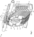
- Figure 1 shows the main parts of the optical fiber organizer 1 with a second support 2 with a first support 3 and several storage means 4.
- the second support 2 is embodied as a base plate 8, e.g. as a grooved plate which comprises first means 5 for receiving, storing and guiding optical cables and optical fibers.
- the second support 2 may be part of a housing for the organizer.
- the first means 5 may be embodied as walls, openings or pins.
- the second support 2 furthermore provides a receiving area 6 for receiving a cable 7 which may comprise several optical fibers.
- the cable 7 may end in the receiving area 6 or may be guided through the receiving area 6.
- the receiving area 6 is disposed in an edge region defined by the base plate 8 of the second support 2 and a sidewall 9 of the second support 2.
- the cable 7 may be fixed to the second support 2 by cable-fixing elements (not shown).
- the organizer trays 10 have a basic shape of a plate and are arranged in parallel to each other and in parallel to the base plate 8.
- the organizer trays 10 may be constructed identically.
- Each organizer tray 10 may comprise fiber guiding means 11 and splice fixing means 12.
- Each of the organizer trays 10 is rotatably connected to the first support 3 by hinge means 13.
- the hinge means 13 allows for a rotation of the organizer tray 10 around a predetermined rotational axis. In this embodiment, the rotational axis is arranged in parallel to the direction of the cable 7 in the receiving area 6 and to a plane of the first support 3.
- the first support 3 may be embodied in the shape of a plate which is also rotatably fixed to the second support 2 by means of a second hinge means 15.
- the second hinge means 15 is arranged at a first rim of the first support 3 which is dedicated to the base plate 8.
- second clip means 16 are disposed which fix the first support 3 in the shown closed position.
- the second clip means 16 comprise a nose and a recess which are arranged on the first support 3 and on the sidewall 9.
- the sidewall 9 has two bars 17, 18. At free ends of the first and second bar 17, 18, a part of the second clip means 16 are disposed.
- the trays 10 constitute individual optical fiber storage means for storing lengths of fiber, commonly referred to as "pig tails" for connecting to other optical fibers or components located on or in the individual trays.
- the trays comprise fiber guide elements and holders 12 which are designed to hold optical fiber splices.
- the first support 3 comprises a molded structure having a plurality of pairs of mounting means in the form of integrally molded protrusions containing apertures for receiving hinge pins formed on the respective optical fiber storage trays 10.
- the protrusions and the respective hinge pins define a hinge axis around which the respective trays 10 rotate relative to the first support 3.
- the second support 2 has a second sidewall 44 which is arranged in parallel to the first sidewall 9.
- the second sidewall 44 has a recess 50 in an area adjacent to rims of the trays 10.
- Each of the trays comprises a slit 52 which is arranged in the middle of the tray 10 and in parallel to a moving direction of the trays from an open to a closed position. Therefore, it is possible to fix the trays 10 with one bolt which is screwed in a thread 53 on the bottom of the base plate 8 ( Fig. 3 ).
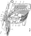
- Figure 2 shows the upper organizer tray 10 which is rotated from the close position of Figure 1 into an open position. In the open position, a second organizer tray 19 is accessible. This is necessary for mounting the fiber and/or the splices in the second organizer tray 19.
- the first clip means 20 are constructed for example as a nose and a recess which are configured to fix the trays 10, 19 in the closed position ( Figure 1 ) relative to the first support 3 and in the open position ( Figure 2 ) relative to the first support 3.
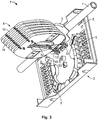
- Figure 3 shows the situation in which all the trays 10, 19 are rotated in the open position.
- the second hinge means 15 can be seen, which rotatably connect the first support 3 to the second support 2.
- Figure 4 shows the situation that the first clip means 20 are loosened and the first support 3 is rotated in an open position.
- the first support 3 In the open position, the first support 3 is arranged vertically to the base plate 8.
- the first support 3 comprises two snap arms 21, 22 at a side which is dedicated to the sidewall 9.
- the snap arms 21, 22 engage with recesses 23, 24 of the first and second bars 17, 18 to fix the first support 3 in the closed position.
- the snap arms 21, 22 and the recesses 23, 24 constitute the second clip means 16.
- a locking means 26 is arranged which locks the first support 3 in the open position.
- the locking means 26 is embodied as a pin which is stuck into the second opening 27 of the base plate 8. If the first support 3 is in the open position as shown in Figure 4 , the area 28 between the first support 3 and the second support 2 can easily be accessed. In the area 28, the optical fiber cable 7 is broken out to separate the individual mini-tubes, each of which may contain a dozen or so optical fibers that are to be arranged and spliced within the optical fiber organizer. Thus, it is possible to easily access a cable 7, optical components, splitters or other elements which may be disposed in the area 28. In the open position of the first support 3, rims of the trays 10, 11 protrude in the recess 50 of the second sidewall 44.
- the height of the staple of the trays 10, 19 of the optical fiber organizer 1 in Figure 4 is higher than in the position of Figure 1 . Furthermore, free space is available for accessing the cable 7 in the area 28 between the first support 3 and the second support 2 in the position of the first support of Figure 4 .
- Figure 5 shows a basic embodiment of the optical fiber organizer with a first support 3 comprising a first and a second section 31, 32.
- the first and the second section are connected by third hinge means 33, which allows a rotation of the first section 31 relative to the second section 32 as shown in Figure 5 and as depicted by the arrow.
- second locking means 51 disposed which lock the two sections 31, 32 in a straight and/or in an inclined position as shown.
- the locking means 51 may be embodied as a pair of a latch and a recess.
- the main difference between the FIST organizer the FOSC organizer is that in the FIST organizer, the storage means are arranged at a predetermined angle relative to the plane of the first support 3.
- the FOSC organizer uses storage means 4 which are basically arranged in parallel to the plane of the first support 3.
- the first section 31 is locked in the inclined position.
- the first section 31 is locked in the straight position.
- the first and second section may be embodied identical, especially have fixing means for fixing storage means 4, especially storage trays.
- the first support comprises a third and a fourth section 34, 35. Each section may be rotatably connected by third hinge means may be arranged between adjacent sections.
- the embodiment of the optical fiber organizer shown in Figures 1 to 4 relates to a FIST application.
- FIG. 6 shows a schematic drawing of a FOSC application, whereby on a second support 2 two first supports 3 are disposed. Between the two first supports 3, the cable 7 and/or further elements are arranged.
- Each first support 3 comprises several sections 31, 32, 34, 35 which are connected to the second support 2.
- the first section 31 of the first support 3 is detachably connected to the second support 2 by first clip means 20.
- the two first sections 31 of the two adjacently arranged first supports 3 are disposed at a predetermined angle of about 45° with regard to the plane of the second support 2.
- first chip means 20 there might be a second locking means 51 which locks the first section in the inclined position as explained referring to fig. 5 with third hinge means 33 and second locking means 51 between two adjacent section of a first support 3.
- two first supports 3 may be designed as explained referring to fig. 5 .
- the storage means 4 are rotatably connected to the first section 31 by a hinge means 13, as explained in Figures 1 to 4 .
- the first clip means 20 of the first sections 31 of the two first supports 3 are removed and the first sections 31 are rotated away from the area 28, as shown in Figure 7 . In this position, it is possible to have an enlarged free space in order to access the area 28 or the cable 7. Furthermore, in the area 28, several elements, e.g. optical components, splitters etc. may be disposed. If there are second locking means between the first and the second section 31, 32, the first chip means 20 is not required.
- each first support 3 is rotatably connected to the second section 32 of the respective first support 3 by third hinge means 33.
- Figure 8 shows a further embodiment of a FOSC optical fiber organizer 1 with a first support 3 with a first, second, third and fourth section 31, 32, 34, 35.
- the second, third and/or the fourth section 32, 34, 35 are fixed to the second support 2.
- the first section 31 is arranged with a predetermined angle relative to the other sections 32, 34, 35 being disposed above the other sections 32, 34, 35.
- the first section 31 covers the area 28 in which the cable 7 or further elements, e.g. splitters, optical components etc., are arranged.
- the first section 31 is rotatably connected to the second support 2 by second clip means 16.
- the storage means 4 which are disposed as trays 10, 19 are rotatably connected to the first section 31 by hinge means 13.
- the first section 31 is rotatably connected to the second section 32 by third hinge means 33.
- the first section 31 of the first support 3 may be connected to a sidewall 9 of the second support 2 by the second clip means 16. If the area 28 is to be accessed, the second clip means 16 are loosened and the first section 31 can be rotated via the rotational axis of third hinge means 33 away from the sidewall 9 as depicted by the arrow shown in Figure 8 . Thus, it is possible to access the area 28.
- the first support 3 may be embodied in the same design as the first support 3 of figure 5 , whereby each section is rotatably connected to one adjacent section and second locking means are arranged between two adjacent sections.
- Figure 9 shows a further embodiment of a FIST optical fiber organizer 1 with a second support 2 and a first support 3.
- the first support 3 is made of a first, a second, a third and a fourth section 31, 32, 34, 35. At least the fourth section 35 is detachable fixed to the base plate 8.
- the first section 31 is connected to the second support 2 by a second clip means 16, e.g. to the sidewall 9.
- each section 31, 32, 34, 35 is rotatably connected to the adjacent section by a third hinge means 33.
- storage means 4 are also rotatably connected to the first, the second and the third section 31, 32 and 34.
- the storage means 4 are embodied as trays 10, 19 which are connected by hinge means (not shown), as shown in detail in Figures 1 to 4 .
- second locking means 51 are arranged between the first and the second section 31, 32 and between the second and the third section 32, 34.
- the locking means 51 hold the first, second and third section 31, 32, 34 in one plane in a stable manner. If the area between the base plate 8 of the second support 2 and the first support 3 in which e.g. the cable 7 or further elements are disposed is to be accessed, the second clip means 16 is removed and the first, the second and the third section 31, 32, 34 are rotated around the rotational axis of the third hinge means 33 which is disposed between the third and the fourth section 34, 35. Depending on the used embodiment, the second clip means 16 is not provided.
- the first support 3 is designed as explained referring to fig. 5 .
- Figure 10 shows a combination of a FIST and a FOSC optical fiber organizer 1 with a first support 3 and a further first support 43.
- the further first support 43 comprises a first and a second section 31, 32, the first and the second section 31, 32 being fixed to one another and to the second support 2.
- the second section 32 is rotatably connected to the second support 2 by second hinge means 15. Furthermore, the first and/or the second section 31, 32 are connected to the second support 2 by detachable second clip means 16. If the area 26 between the first and the second support 3, 2 is to be accessed, the second clip means 16 is released and the first support 3 is rotated in the direction of the adjacent sidewall 9 of the second support 2, as depicted by the arrow.
- a further first support 43 Adjacent and in one plane to the first support 3, a further first support 43 is disposed.
- the further first support 43 comprises a T-groove plate 45.
- Two storage means 4 embodied e.g. as trays 10, 19 are rotatably connected to the T-groove plate 45 by hinge means.
- the storage means 4 are arranged in parallel to the plane of the further sections 32, 31 of the further first support 43.
- the T-groove plate 45 is fixed to the second support 2 by a further clip means 46.
- the T-grooved plate 45 is rotatably connected to a second section 32 of the first support 3 by a third hinge means 33.
- the further clip means 46 is removed and the T-groove plate 45 is rotated around the rotational axis of the third hinge means 33 in the direction of a second sidewall 4, as depicted by the arrow.
- Figure 11 shows a further embodiment of an optical fiber organizer 1 with a first support 3 with a first, second, third, fourth, fifth and sixth section 31, 32, 34, 35, 36, 37.
- the first and the second section 31, 32 are fixed to each other by second locking means 51 and several storage means 4 are fixed to the first and second section 31, 32 by hinge means (not shown).
- the third section 34 is fixed to the second support 2.
- the third, the fourth and the fifth section 34, 35, 36 are fixed to one another.
- the sixth section 37 is rotatably connected to the fifth section 36 by a third hinge means 33.
- second locking means 51 arranged between the fifth and sixth section 36, 37.
- the sixths section 37 is fixed in the inclined position as shown.
- the second section 32 is rotatably connected to the third section 34 by a third hinge means 33.
- the sixth section 37 is bent away from the base plate 8 of the second support 2.
- Storage means 4 are rotatably connected to the sixth section 37 by hinge means 13.
- the storage means 4 of the sixth section 37 are arranged as plate-shaped trays which are disposed in parallel to the base plate 8.
- the first section 31 and the fifth section 36 may be connected to the second support 2 by means of second clip means 16. Between the first section 31 and the base plate 8 or between the sixth section 37 and the base plate 8, the cable or other optical components such as splitters may be disposed.
- the respective second clip means 16 and/or the second locking means 51 is loosened.
- the first and the second section 31, 32 can then be rotated in the direction of the sixth section 37 around the axis disposed by the third hinge means 33.
- the respective second clip means 16 and/or the second locking means 51 is loosened and the sixth section 37 is rotated around the rotational axis which is disposed by the third hinge means 33, as depicted by an arrow in Figure 11 .
- Figure 12 shows a further embodiment of an optical fiber organizer 1 with a first support 3 comprising a first, second, third, fourth, fifth and a sixth section 31, 32, 34, 35, 36, 37.
- the first and the second section 31, 32 are connected to the second support 2.
- the third section 34 is rotatably connected by a third hinge means 33 to the second section 32.
- the third section 34 is e.g. embodied as a T-groove plate.
- a part of the third section 34 is inclined in a direction away from the base plate 8.
- storage means 4 are rotatably connected to the third section 34 by hinge means 13.
- the third section 34 is connected to the base plate 8 by second clip means 16.
- the fourth and fifth section 35, 36 are connected to the base plate 8 of the second support 2.
- the sixth section 37 is rotatably connected to the fifth section 36 by a hinge means 33.
- An end part of the sixth section 37 is inclined in a direction away from the base plate 8.
- two storage means 4 are rotatably connected to the sixth section 37 by hinge means 13.
- the sixth section 37 is connected to a sidewall 9 of the second support 2 by further clip means 46. If the area 28 between the third section 34 or the sixth section 37 is to be accessed, the second clip means 16 or the further clip means 46 have to be released.
- the third section 34 can then be rotated around the rotational axis of the third hinge means 33 in direction of a second sidewall 44 of the second support 2, as it is depicted by an arrow.
- the sixth section 37 can be rotated around the axis of the third hinge means 33 in the direction of the second sidewall 4, as it is depicted by the arrow.
- the cable 7 or other components e.g. optical components of splitters may be disposed.
- each section may be connected with an adjacent section rotatably by a third hinge means and by a second locking means 51 as explained referring to fig. 5 .
- Figure 13 shows an embodiment with two first sections 3 as explained in fig. 5 .
- the first sections 31 are detachably fixed by a second clip means 16 to the second support 2.
- At least one of the fourth, third or second section 35, 34, 32 is detachable fixed to the second support 2.
- the second support 2 may be part of a housing.
- one of the first support 3 may be proposed as shown in figure 9 in a straight position with trays arranged in an inclined manner relative to the plane of the second support 2.
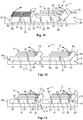
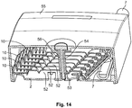
- Figure 14 shows a cross-sectional view of a housing for the embodiment of the figures 1 to 4
- the second support 2 is covered by a cover 55.
- a bolt 54 is guided from the cover 55 via the slits 52 of the trays 10 to the thread 53 fixing the cover 55 to the second support 2.
Landscapes
- Physics & Mathematics (AREA)
- General Physics & Mathematics (AREA)
- Optics & Photonics (AREA)
- Light Guides In General And Applications Therefor (AREA)
- Mechanical Coupling Of Light Guides (AREA)
Abstract
Description
- The present invention relates to the management of optical fiber connections and in particular concerns an optical fiber organizer and splice holder.
- A known type of optical fiber organizer is described in
PCT application WO 97/32231 A1 PCT application WO 2009/106874 A1 . The optical fiber organizer comprises an optical fiber storage means which is fixed to a support. The support comprises a cable termination retention means for securing incoming/outgoing cables having at least one optical fiber. The support is fixed to a casing of the optical fiber organizer. For each optical fiber storage means, one cable termination retention means is provided. The optical fiber storage means is rotatably connected to the support. The cable is guided in an area between the fiber storage means and the support. - The object of the invention is to provide an improved optical fiber organizer. The object of the invention is achieved by the optical fiber organizer according to
claim 1. The optical fiber organizer has the advantage that the proposed organizer provides a higher flexibility. This advantage is attained by a first support which is rotatably connected to a further element. - Further embodiments of the invention are disclosed in the dependent claims.
- An embodiment of the optical fiber organizer has the advantage that the area between the first support of the fiber storage means and a second support can easily be accessed. This advantage is achieved by rotatably connecting the first support to a second support. For this reason, it is possible to rotate the first support away from the second support. Thus, it is possible to more easily access elements such as the cable, splitters, optical fiber etc. which may be arranged between the first and the second support.
- In one embodiment, the storage means and the first support comprise clip means which clip the storage means in an open position relative to an adjacent storage means. For this reason, it is possible to fix the position of the storage means and, if it is advantageous, to loosen the clip means and to rotate the storage means in a further position.
- In a further embodiment the first support comprises a first and a second section, which are rotatably connected. Therefore, it is possible to use the first support in different application, for example for a FOSC application or a FIST application. It is not necessary to produce different first supports. Furthermore, the application can be changed without having the need to use different first supports. Preferably, there is a second locking means which allows the locking of the first section in an inclined position referred to the second section. Furthermore, the first and/or second section may be fixed to a second support.
- In a further embodiment, the first and the second support comprise second clip means which allow clipping the first support in a closed position relative to the second support. This means that, if it is not necessary to access the space between the first and the second support, the second clip means fix the first support closely to the second support. This provides a fiber organizer with a small constructed space. If it is necessary to access the space between the first and the second support, the second clip means can be loosened and the first support can be moved into an open position which means that through the larger space available between the first and the second support elements such as the cable, the fiber, optical components and/or splitters can easily be accessed.
- In a further embodiment, several storage means are fixed to a first support and/or to a first and second section of the first support.
- In a further embodiment, the optical fiber organizer comprises several first supports which are adjacently arranged and which are rotatably connected to the second support. As a result, it is possible to access all sections of the second support for accessing the elements.
- In a further embodiment, the storage means is embodied as a plate with a guiding means for an optical fiber and/or a fixing means for a splice of optical fibers.
- In a further embodiment, the optical fiber organizer comprises two first supports with a first and at least one second section, whereby the first supports are adjacently arranged and the respective first sections are rotatably connected to the respective second section in opposite directions.
- Depending on the used embodiment, the fiber storing means are arranged in parallel to the second support or with a predetermined angle.
- In a further embodiment, the first support is embodied as a groove plate, e.g. as a T-groove plate. The T-groove plate allows bending and straight routing of the fiber.
- Various embodiments of the present invention will now be described in more detail by way of example only, with reference to the accompanying drawings in which:
-
Figure 1 is a perspective view of a part of an optical fiber organizer with fiber storage means, a first support and a second support and a fiber cable; -
Figure 2 shows the optical fiber organizer ofFigure 1 whereby a storage means is in an open position; -
Figure 3 shows the optical fiber organizer ofFigure 1 whereby all fiber storage means are arranged in the open position; -
Figure 4 shows the optical fiber organizer with a first support being in an open position; -
Figure 5 shows a schematic drawing of a first support with two sections; -
Figure 6 shows a further embodiment of an optical fiber organizer with two first supports with fiber storage means which are arranged in parallel to the second support; -
Figure 7 is a schematic drawing of the optical fiber organizer ofFig. 6 with the first supports being in an open position; -
Figure 8 is a further embodiment of an optical fiber organizer; -
Figure 9 is a further embodiment of an optical fiber organizer; -
Figure 10 is a further embodiment with an optical fiber organizer; -
Figure 11 shows a further embodiment of an optical fiber organizer; -
Figure 12 is a further embodiment of an optical fiber organizer; and -
Figure 13 shows a further embodiment of an optical fiber organizer. -
Figure 14 shows a cross sectional view of a housing of the optical fiber organizer. -
Figure 1 shows the main parts of theoptical fiber organizer 1 with asecond support 2 with afirst support 3 and several storage means 4. Thesecond support 2 is embodied as abase plate 8, e.g. as a grooved plate which comprisesfirst means 5 for receiving, storing and guiding optical cables and optical fibers. Thesecond support 2 may be part of a housing for the organizer. Thefirst means 5 may be embodied as walls, openings or pins. Thesecond support 2 furthermore provides a receiving area 6 for receiving acable 7 which may comprise several optical fibers. Thecable 7 may end in the receiving area 6 or may be guided through the receiving area 6. The receiving area 6 is disposed in an edge region defined by thebase plate 8 of thesecond support 2 and asidewall 9 of thesecond support 2. Thecable 7 may be fixed to thesecond support 2 by cable-fixing elements (not shown). - Above the
base plate 8, several storage means 4 which are embodied asorganizer trays 10 are disposed. Theorganizer trays 10 have a basic shape of a plate and are arranged in parallel to each other and in parallel to thebase plate 8. Theorganizer trays 10 may be constructed identically. Eachorganizer tray 10 may comprise fiber guiding means 11 and splice fixing means 12. Each of theorganizer trays 10 is rotatably connected to thefirst support 3 by hinge means 13. The hinge means 13 allows for a rotation of theorganizer tray 10 around a predetermined rotational axis. In this embodiment, the rotational axis is arranged in parallel to the direction of thecable 7 in the receiving area 6 and to a plane of thefirst support 3. - The
first support 3 may be embodied in the shape of a plate which is also rotatably fixed to thesecond support 2 by means of a second hinge means 15. The second hinge means 15 is arranged at a first rim of thefirst support 3 which is dedicated to thebase plate 8. At an opposite rim, second clip means 16 are disposed which fix thefirst support 3 in the shown closed position. The second clip means 16 comprise a nose and a recess which are arranged on thefirst support 3 and on thesidewall 9. In the shown embodiment, thesidewall 9 has twobars second bar - The
trays 10 constitute individual optical fiber storage means for storing lengths of fiber, commonly referred to as "pig tails" for connecting to other optical fibers or components located on or in the individual trays. The trays comprise fiber guide elements andholders 12 which are designed to hold optical fiber splices. Thefirst support 3 comprises a molded structure having a plurality of pairs of mounting means in the form of integrally molded protrusions containing apertures for receiving hinge pins formed on the respective opticalfiber storage trays 10. The protrusions and the respective hinge pins define a hinge axis around which therespective trays 10 rotate relative to thefirst support 3. - The
second support 2 has asecond sidewall 44 which is arranged in parallel to thefirst sidewall 9. Thesecond sidewall 44 has arecess 50 in an area adjacent to rims of thetrays 10. - Each of the trays comprises a
slit 52 which is arranged in the middle of thetray 10 and in parallel to a moving direction of the trays from an open to a closed position. Therefore, it is possible to fix thetrays 10 with one bolt which is screwed in athread 53 on the bottom of the base plate 8 (Fig. 3 ). -
Figure 2 shows theupper organizer tray 10 which is rotated from the close position ofFigure 1 into an open position. In the open position, asecond organizer tray 19 is accessible. This is necessary for mounting the fiber and/or the splices in thesecond organizer tray 19. There are first clip means 20 disposed on thefirst support 3 and thetrays tray 10 in the closed and/or open position. - The first clip means 20 are constructed for example as a nose and a recess which are configured to fix the
trays Figure 1 ) relative to thefirst support 3 and in the open position (Figure 2 ) relative to thefirst support 3. -
Figure 3 shows the situation in which all thetrays first support 3 to thesecond support 2. -
Figure 4 shows the situation that the first clip means 20 are loosened and thefirst support 3 is rotated in an open position. In the open position, thefirst support 3 is arranged vertically to thebase plate 8. Thefirst support 3 comprises twosnap arms sidewall 9. Thesnap arms recesses second bars first support 3 in the closed position. Thesnap arms recesses - Furthermore, a locking means 26 is arranged which locks the
first support 3 in the open position. The locking means 26 is embodied as a pin which is stuck into thesecond opening 27 of thebase plate 8. If thefirst support 3 is in the open position as shown inFigure 4 , thearea 28 between thefirst support 3 and thesecond support 2 can easily be accessed. In thearea 28, theoptical fiber cable 7 is broken out to separate the individual mini-tubes, each of which may contain a dozen or so optical fibers that are to be arranged and spliced within the optical fiber organizer. Thus, it is possible to easily access acable 7, optical components, splitters or other elements which may be disposed in thearea 28. In the open position of thefirst support 3, rims of thetrays recess 50 of thesecond sidewall 44. - Due to this new construction, it is possible to provide an optical fiber organizer with a small constructed size which allows large free access to the
cable 7 and other components which are arranged in thearea 28 between the first and thesecond support - As becomes obvious when comparing the situation of
Figure 1 andFigure 4 , the height of the staple of thetrays optical fiber organizer 1 inFigure 4 is higher than in the position ofFigure 1 . Furthermore, free space is available for accessing thecable 7 in thearea 28 between thefirst support 3 and thesecond support 2 in the position of the first support ofFigure 4 . - In
Figures 1 to 4 , a cover is not shown which is fixed to the base plate in order to enclose the optical fiber organizer. -
Figure 5 shows a basic embodiment of the optical fiber organizer with afirst support 3 comprising a first and asecond section first section 31 relative to thesecond section 32 as shown inFigure 5 and as depicted by the arrow. Furthermore, there are second locking means 51 disposed which lock the twosections first support 3 with several sections can be applied to different types of optical fiber organizers, e.g. the type FIST application, and to the type FOSC application, as shown inFigure 5 . The main difference between the FIST organizer the FOSC organizer is that in the FIST organizer, the storage means are arranged at a predetermined angle relative to the plane of thefirst support 3. The FOSC organizer uses storage means 4 which are basically arranged in parallel to the plane of thefirst support 3. For the FOCS application thefirst section 31 is locked in the inclined position. For the FIST application thefirst section 31 is locked in the straight position. The first and second section may be embodied identical, especially have fixing means for fixing storage means 4, especially storage trays. In the shown embodiment, the first support comprises a third and afourth section Figures 1 to 4 relates to a FIST application. -
Figure 6 shows a schematic drawing of a FOSC application, whereby on asecond support 2 twofirst supports 3 are disposed. Between the twofirst supports 3, thecable 7 and/or further elements are arranged. Eachfirst support 3 comprisesseveral sections second support 2. Thefirst section 31 of thefirst support 3 is detachably connected to thesecond support 2 by first clip means 20. The twofirst sections 31 of the two adjacently arranged first supports 3 are disposed at a predetermined angle of about 45° with regard to the plane of thesecond support 2. The twofirst sections 31 of thefirst supports 3, which are arranged in an inclined manner, cover thearea 28 in which thecable 7 and/or other optical components is disposed. Instead of the first chip means 20, there might be a second locking means 51 which locks the first section in the inclined position as explained referring tofig. 5 with third hinge means 33 and second locking means 51 between two adjacent section of afirst support 3. In a further embodiment, twofirst supports 3 may be designed as explained referring tofig. 5 . - The storage means 4 are rotatably connected to the
first section 31 by a hinge means 13, as explained inFigures 1 to 4 . - If a free space for accessing the
area 28 or thecable 7 is required, the first clip means 20 of thefirst sections 31 of the twofirst supports 3 are removed and thefirst sections 31 are rotated away from thearea 28, as shown inFigure 7 . In this position, it is possible to have an enlarged free space in order to access thearea 28 or thecable 7. Furthermore, in thearea 28, several elements, e.g. optical components, splitters etc. may be disposed. If there are second locking means between the first and thesecond section - The
first section 31 of eachfirst support 3 is rotatably connected to thesecond section 32 of the respectivefirst support 3 by third hinge means 33. -
Figure 8 shows a further embodiment of a FOSCoptical fiber organizer 1 with afirst support 3 with a first, second, third andfourth section fourth section second support 2. Thefirst section 31 is arranged with a predetermined angle relative to theother sections other sections first section 31 covers thearea 28 in which thecable 7 or further elements, e.g. splitters, optical components etc., are arranged. Thefirst section 31 is rotatably connected to thesecond support 2 by second clip means 16. The storage means 4 which are disposed astrays first section 31 by hinge means 13. Thefirst section 31 is rotatably connected to thesecond section 32 by third hinge means 33. Thefirst section 31 of thefirst support 3 may be connected to asidewall 9 of thesecond support 2 by the second clip means 16. If thearea 28 is to be accessed, the second clip means 16 are loosened and thefirst section 31 can be rotated via the rotational axis of third hinge means 33 away from thesidewall 9 as depicted by the arrow shown inFigure 8 . Thus, it is possible to access thearea 28. Thefirst support 3 may be embodied in the same design as thefirst support 3 offigure 5 , whereby each section is rotatably connected to one adjacent section and second locking means are arranged between two adjacent sections. -
Figure 9 shows a further embodiment of a FISToptical fiber organizer 1 with asecond support 2 and afirst support 3. Thefirst support 3 is made of a first, a second, a third and afourth section fourth section 35 is detachable fixed to thebase plate 8. Thefirst section 31 is connected to thesecond support 2 by a second clip means 16, e.g. to thesidewall 9. In the shown embodiment, eachsection third section trays Figures 1 to 4 . For this reason, second locking means 51 are arranged between the first and thesecond section third section third section base plate 8 of thesecond support 2 and thefirst support 3 in which e.g. thecable 7 or further elements are disposed is to be accessed, the second clip means 16 is removed and the first, the second and thethird section fourth section first support 3 is designed as explained referring tofig. 5 . -
Figure 10 shows a combination of a FIST and a FOSCoptical fiber organizer 1 with afirst support 3 and a furtherfirst support 43. The furtherfirst support 43 comprises a first and asecond section second section second support 2. Thesecond section 32 is rotatably connected to thesecond support 2 by second hinge means 15. Furthermore, the first and/or thesecond section second support 2 by detachable second clip means 16. If thearea 26 between the first and thesecond support first support 3 is rotated in the direction of theadjacent sidewall 9 of thesecond support 2, as depicted by the arrow. Adjacent and in one plane to thefirst support 3, a furtherfirst support 43 is disposed. The furtherfirst support 43 comprises a T-groove plate 45. Two storage means 4 embodied e.g. astrays groove plate 45 by hinge means. The storage means 4 are arranged in parallel to the plane of thefurther sections first support 43. The T-groove plate 45 is fixed to thesecond support 2 by a further clip means 46. Furthermore, the T-groovedplate 45 is rotatably connected to asecond section 32 of thefirst support 3 by a third hinge means 33. If thearea 28 between the T-groovedplate 45 and thebase plate 8 of thesecond support 2 is to be accessed, the further clip means 46 is removed and the T-groove plate 45 is rotated around the rotational axis of the third hinge means 33 in the direction of asecond sidewall 4, as depicted by the arrow. -
Figure 11 shows a further embodiment of anoptical fiber organizer 1 with afirst support 3 with a first, second, third, fourth, fifth andsixth section second section second section third section 34 is fixed to thesecond support 2. The third, the fourth and thefifth section sixth section 37 is rotatably connected to thefifth section 36 by a third hinge means 33. Furthermore, there are second locking means 51 arranged between the fifth andsixth section sixths section 37 is fixed in the inclined position as shown. Moreover, thesecond section 32 is rotatably connected to thethird section 34 by a third hinge means 33. Thesixth section 37 is bent away from thebase plate 8 of thesecond support 2. Storage means 4 are rotatably connected to thesixth section 37 by hinge means 13. The storage means 4 of thesixth section 37 are arranged as plate-shaped trays which are disposed in parallel to thebase plate 8. Depending on the embodiment, thefirst section 31 and thefifth section 36 may be connected to thesecond support 2 by means of second clip means 16. Between thefirst section 31 and thebase plate 8 or between thesixth section 37 and thebase plate 8, the cable or other optical components such as splitters may be disposed. If thearea 28 between thefirst section 31 and thebase plate 8 or thearea 28 between thesixth section 37 and thebase plate 8 are to be accessed, the respective second clip means 16 and/or the second locking means 51is loosened. The first and thesecond section sixth section 37 around the axis disposed by the third hinge means 33. Furthermore, if a person would like to access thearea 28 beneath thesixth section 37, the respective second clip means 16 and/or the second locking means 51 is loosened and thesixth section 37 is rotated around the rotational axis which is disposed by the third hinge means 33, as depicted by an arrow inFigure 11 . -
Figure 12 shows a further embodiment of anoptical fiber organizer 1 with afirst support 3 comprising a first, second, third, fourth, fifth and asixth section second section second support 2. Thethird section 34 is rotatably connected by a third hinge means 33 to thesecond section 32. Thethird section 34 is e.g. embodied as a T-groove plate. A part of thethird section 34 is inclined in a direction away from thebase plate 8. At the inclined section, storage means 4 are rotatably connected to thethird section 34 by hinge means 13. Thethird section 34 is connected to thebase plate 8 by second clip means 16. The fourth andfifth section base plate 8 of thesecond support 2. Thesixth section 37 is rotatably connected to thefifth section 36 by a hinge means 33. An end part of thesixth section 37 is inclined in a direction away from thebase plate 8. At the inclined section, two storage means 4 are rotatably connected to thesixth section 37 by hinge means 13. Thesixth section 37 is connected to asidewall 9 of thesecond support 2 by further clip means 46. If thearea 28 between thethird section 34 or thesixth section 37 is to be accessed, the second clip means 16 or the further clip means 46 have to be released. Thethird section 34 can then be rotated around the rotational axis of the third hinge means 33 in direction of asecond sidewall 44 of thesecond support 2, as it is depicted by an arrow. Furthermore, thesixth section 37 can be rotated around the axis of the third hinge means 33 in the direction of thesecond sidewall 4, as it is depicted by the arrow. In thearea 28, thecable 7 or other components, e.g. optical components of splitters may be disposed. Depending on the used embodiment each section may be connected with an adjacent section rotatably by a third hinge means and by a second locking means 51 as explained referring tofig. 5 . -
Figure 13 shows an embodiment with twofirst sections 3 as explained infig. 5 . Thefirst sections 31 are detachably fixed by a second clip means 16 to thesecond support 2. At least one of the fourth, third orsecond section second support 2. Thesecond support 2 may be part of a housing. Depending on the use embodiment, one of thefirst support 3 may be proposed as shown infigure 9 in a straight position with trays arranged in an inclined manner relative to the plane of thesecond support 2. -
Figure 14 shows a cross-sectional view of a housing for the embodiment of thefigures 1 to 4 Thesecond support 2 is covered by acover 55. Abolt 54 is guided from thecover 55 via theslits 52 of thetrays 10 to thethread 53 fixing thecover 55 to thesecond support 2. Depending on the used embodiment, there is aguidance 56 from thecover 55 to thethread 53, whereby thebolt 54 is arranged in theguidance 56. -
- 1
- optical fiber organizer
- 2
- second support
- 3
- first support
- 4
- storage means
- 5
- first means
- 6
- receiving area
- 7
- cable
- 8
- base plate
- 9
- sidewall
- 10
- tray
- 11
- fiber guiding means
- 12
- splice fixing means
- 13
- hinge means
- 15
- second hinge means
- 16
- second clip means
- 17
- first bar
- 18
- second bar
- 19
- second tray
- 20
- first clip means
- 21
- first snap arm
- 22
- second snap arm
- 23
- first recess
- 24
- second recess
- 26
- locking means
- 27
- second opening
- 28
- area
- 31
- first section first support
- 32
- second section first support
- 33
- third hinge means
- 34
- third section first support
- 35
- fourth section first support
- 36
- fifth section first support
- 37
- sixth section first support
- 43
- further first support
- 44
- second sidewall
- 45
- T-grooved plate
- 46
- further clip means
- 50
- recess
- 51
- second locking means
- 52
- slit
- 53
- thread
- 54
- bolt
- 55
- cover
- 56
- guidance for a bolt
Claims (13)
- An optical fiber organizer assembly comprising:a. a first support comprising a first section rotatably connected to a second section with a hinge, the first section being rotatable between a straight position and a plurality of inclined positions with respect to the second section;b. a plurality of optical-fiber storage trays rotatably connected to the first section with a plurality of hinges; andc. an area supporting a cable and/or other optical components, the area being in a covered position when the first section is in a first inclined position angled toward the area, and the area being in an access position when the first section is in a second inclined position angled away from the area.
- The optical fiber organizer assembly of claim 1, further comprising:a. an additional first support comprising a first section rotatably connected to a second section with a hinge, the first section being rotatable between a straight position and a plurality of inclined positions with respect to the second section; andb. an additional plurality of optical-fiber storage trays rotatably connected to the additional first section of the second support with a plurality of hinges, the area being in a covered position when the first section of the additional first support is in a first inclined position angled toward the area, and the area being in an access position when the first section of the additional first support is in a second inclined position angled away from the area;wherein, the area is positioned between the first section of the first support and the first section of the additional first support.
- The optical fiber organizer assembly of claim 1, further comprising a lock disposed between the first section and the second section, the lock holding the first section in either the straight position or one of the plurality of inclined positions.
- The optical fiber organizer assembly of claim 1, further comprising a second support connected to the first support, the second support defined along a plane.
- The optical fiber organizer assembly of claim 1, wherein when the area is in the covered position, the first section is rotated toward the area at an angle of about 45° with respect to the plane of the second support.
- The optical fiber organizer assembly of claim 1, wherein the first section is detachably connected to the second support with a clip.
- The optical fiber organizer assembly of claim 1, wherein the first support further comprises a third section and a fourth section, the second section, the third section and the fourth section are connected to the second support.
- The optical fiber organizer assembly of claim 1, further comprising a holder for holding the first section in at least one of the straight position and the plurality of inclined positions.
- The optical fiber optical fiber organizer assembly of claim 1, further comprising a base mounted to at least one of the first and second sections.
- The optical fiber optical fiber organizer assembly of claim 1, wherein the second section comprises a base.
- The optical fiber optical fiber organizer assembly of claim 1, further comprising a plurality of first sections or a plurality of second sections.
- The optical fiber optical fiber organizer assembly of claim 1, further comprising a plurality of first sections and a plurality of second sections.
- The optical fiber optical fiber organizer assembly of claim 1, further comprising a base holding one or more first sections and one or more of second sections.
Priority Applications (1)
| Application Number | Priority Date | Filing Date | Title |
|---|---|---|---|
| EP17174566.4A EP3239753B1 (en) | 2011-02-17 | 2011-02-17 | Optical fiber organizer |
Applications Claiming Priority (2)
| Application Number | Priority Date | Filing Date | Title |
|---|---|---|---|
| EP11154906A EP2490058A1 (en) | 2011-02-17 | 2011-02-17 | Optical fiber organizer with trays mounted on pivoting support |
| EP17174566.4A EP3239753B1 (en) | 2011-02-17 | 2011-02-17 | Optical fiber organizer |
Related Parent Applications (1)
| Application Number | Title | Priority Date | Filing Date |
|---|---|---|---|
| EP11154906A Division EP2490058A1 (en) | 2011-02-17 | 2011-02-17 | Optical fiber organizer with trays mounted on pivoting support |
Publications (4)
| Publication Number | Publication Date |
|---|---|
| EP3239753A2 true EP3239753A2 (en) | 2017-11-01 |
| EP3239753A3 EP3239753A3 (en) | 2018-01-24 |
| EP3239753C0 EP3239753C0 (en) | 2023-11-15 |
| EP3239753B1 EP3239753B1 (en) | 2023-11-15 |
Family
ID=45722614
Family Applications (2)
| Application Number | Title | Priority Date | Filing Date |
|---|---|---|---|
| EP17174566.4A Active EP3239753B1 (en) | 2011-02-17 | 2011-02-17 | Optical fiber organizer |
| EP11154906A Ceased EP2490058A1 (en) | 2011-02-17 | 2011-02-17 | Optical fiber organizer with trays mounted on pivoting support |
Family Applications After (1)
| Application Number | Title | Priority Date | Filing Date |
|---|---|---|---|
| EP11154906A Ceased EP2490058A1 (en) | 2011-02-17 | 2011-02-17 | Optical fiber organizer with trays mounted on pivoting support |
Country Status (5)
| Country | Link |
|---|---|
| US (3) | US9494759B2 (en) |
| EP (2) | EP3239753B1 (en) |
| CN (1) | CN103443682B (en) |
| RU (2) | RU2617879C2 (en) |
| WO (1) | WO2012110452A1 (en) |
Families Citing this family (24)
| Publication number | Priority date | Publication date | Assignee | Title |
|---|---|---|---|---|
| US9279951B2 (en) | 2010-10-27 | 2016-03-08 | Corning Cable Systems Llc | Fiber optic module for limited space applications having a partially sealed module sub-assembly |
| EP3239753B1 (en) * | 2011-02-17 | 2023-11-15 | Bison Patent Licensing, LLC | Optical fiber organizer |
| NZ700672A (en) | 2012-04-03 | 2017-02-24 | CommScope Connectivity Belgium BVBA | Telecommunications enclosure and organizer |
| US9250409B2 (en) | 2012-07-02 | 2016-02-02 | Corning Cable Systems Llc | Fiber-optic-module trays and drawers for fiber-optic equipment |
| EP2725397B1 (en) * | 2012-10-26 | 2015-07-29 | CCS Technology, Inc. | Fiber optic management unit and fiber optic distribution device |
| US20140247541A1 (en) * | 2013-02-26 | 2014-09-04 | Realm Communications Group, Inc. | Telecom cabinet dual tray slider |
| US9823432B2 (en) | 2013-03-19 | 2017-11-21 | Adc Czech Republic, S.R.O. | Moveable bend control and patch cord support for telecommunications panel |
| CN107076953B (en) | 2014-09-16 | 2020-05-15 | 康普连通比利时私人有限公司 | Multi-position telecommunications carrier |
| NZ762104A (en) * | 2014-09-16 | 2022-12-23 | CommScope Connectivity Belgium BVBA | Telecommunications tray with a cable routing path extending through a pivot hinge |
| EP4398018A3 (en) | 2014-09-16 | 2024-09-18 | CommScope Connectivity Belgium BVBA | Telecommunications tray assembly |
| EP3286588B1 (en) | 2015-04-23 | 2020-01-29 | CommScope Connectivity Belgium BVBA | Telecommunications panel assembly with movable adapters |
| JP6663800B2 (en) * | 2016-06-13 | 2020-03-13 | マスプロ電工株式会社 | Optical receiver housing |
| US10670394B2 (en) * | 2017-06-27 | 2020-06-02 | The Boeing Company | System and method for determining the direction and spacing of fiber paths for a composite ply |
| WO2019079413A1 (en) * | 2017-10-17 | 2019-04-25 | Corning Research & Development Corporation | Fiber optic cable including subunits and related methods |
| EP3701304B1 (en) | 2017-10-26 | 2022-05-04 | CommScope Connectivity Belgium BVBA | Telecommunications system |
| US10578823B2 (en) * | 2017-12-28 | 2020-03-03 | Afl Ig Llc | Wall cabinets and fiber management trays |
| WO2019212887A1 (en) | 2018-05-01 | 2019-11-07 | Commscope Technologies Llc | Tray tower with position indexing trays |
| EP4509895A3 (en) | 2018-05-14 | 2025-06-18 | AFL Telecommunications LLC | Butt closures and organizer assemblies therefor |
| US12210203B2 (en) | 2019-03-29 | 2025-01-28 | Commscope Technologies Llc | Tray hinge interface system with opposing recessed surfaces recessed toward the pivot axis |
| US20220196955A1 (en) * | 2019-03-29 | 2022-06-23 | Commscope Technologies Llc | Optical fiber spice tray organizer |
| EP3916450B1 (en) * | 2020-05-29 | 2023-02-22 | Hauff-Technik GRIDCOM GmbH | Splice module with guide for patch cable |
| JP1721876S (en) * | 2022-01-31 | 2022-08-08 | Optical fiber storage tray | |
| JP1721877S (en) * | 2022-01-31 | 2022-08-08 | Optical fiber storage tray | |
| CN115524815B (en) * | 2022-09-28 | 2025-08-08 | 惠州市飞博康实业有限公司 | Optical fiber splicing box |
Citations (2)
| Publication number | Priority date | Publication date | Assignee | Title |
|---|---|---|---|---|
| WO1997032231A1 (en) | 1996-02-29 | 1997-09-04 | N.V. Raychem S.A. | Optical fibre organizer |
| WO2009106874A1 (en) | 2008-02-29 | 2009-09-03 | Tyco Electronics Raychem Nv | Optical fibre organiser |
Family Cites Families (40)
| Publication number | Priority date | Publication date | Assignee | Title |
|---|---|---|---|---|
| US4266853A (en) * | 1979-03-12 | 1981-05-12 | Northern Telecom Limited | Device for organizing optical fibers and the like |
| JPH063487B2 (en) * | 1988-03-15 | 1994-01-12 | 住友電気工業株式会社 | Multi-fiber optical fiber cable junction box |
| US4832436A (en) * | 1988-10-11 | 1989-05-23 | Fujikura Ltd. | Optical fiber distribution apparatus |
| FR2687744B1 (en) * | 1992-02-21 | 1994-04-08 | Mars Actel | SET OF ARTICULATED FLAT MODULES. |
| FR2687743B1 (en) * | 1992-02-21 | 1995-06-16 | Mars Actel | SET OF STACKED AND ARTICULATED MODULES. |
| US5323480A (en) * | 1992-11-25 | 1994-06-21 | Raychem Corporation | Fiber optic splice closure |
| GB9318633D0 (en) * | 1993-09-08 | 1993-10-27 | Raychem Sa Nv | Organization of optical fibres |
| US6008487A (en) * | 1995-02-02 | 1999-12-28 | Yokogawa Electric Corporation | Optical-fiber inspection device |
| GB2316496B (en) * | 1996-08-09 | 2000-07-26 | Bowthorpe Plc | Optical fibre storage enclosure |
| US6504987B1 (en) | 1996-11-20 | 2003-01-07 | Tyco Electronics Corporation | Optical fiber organizer |
| US5802237A (en) * | 1997-04-18 | 1998-09-01 | Minnesota Mining And Manufacturing Company | Optical fiber organizer |
| US6009224A (en) * | 1997-11-06 | 1999-12-28 | Allen; Barry Wayne | Fiber optic organizer with lockable trays and method of accessing a tray |
| KR100261762B1 (en) * | 1997-12-02 | 2000-07-15 | 이계철 | Optical ribbon fiber splice tray |
| US6009225A (en) * | 1998-05-26 | 1999-12-28 | Ray; Craig D. | Fiber optic drop splice closure and related methods |
| GB2343261B (en) * | 1998-10-29 | 2002-12-11 | Bowthorpe Plc | Optical fibre storage apparatus with movable stacks |
| US6353697B1 (en) * | 1999-07-30 | 2002-03-05 | Lucent Technologies, Inc. | Modular layered splice holder |
| US6418266B1 (en) * | 1999-08-16 | 2002-07-09 | Preformed Line Products Company | Flip tray system for use in an optical fiber splice case |
| US9586699B1 (en) * | 1999-08-16 | 2017-03-07 | Smart Drilling And Completion, Inc. | Methods and apparatus for monitoring and fixing holes in composite aircraft |
| US6453107B1 (en) * | 1999-08-31 | 2002-09-17 | Lucent Technologies Inc. | Tray locking feature for a fiber enclosure |
| US6253016B1 (en) * | 1999-08-31 | 2001-06-26 | Lucent Technologies, Inc. | Wall mounted fiber splice enclosure |
| US6438310B1 (en) * | 2000-01-24 | 2002-08-20 | Adc Telecommunications, Inc. | Cable management panel with sliding drawer |
| US6625374B2 (en) * | 2001-03-07 | 2003-09-23 | Adc Telecommunications, Inc. | Cable storage spool |
| US6701056B2 (en) * | 2002-01-02 | 2004-03-02 | Wavesplitter Technologies, Inc. | Modular, variably configurable retainer assembly for optical components |
| DE10239569A1 (en) * | 2002-08-26 | 2004-03-11 | CCS Technology, Inc., Wilmington | Splice cassette |
| DE10314262A1 (en) | 2002-11-26 | 2004-06-03 | CCS Technology, Inc., Wilmington | Device for structured storage or handling of optical fibers |
| US7200314B2 (en) * | 2004-05-06 | 2007-04-03 | Commscope Solutions Properties, Llc | Carrier for multiple splice trays |
| EP1949161A1 (en) * | 2005-10-24 | 2008-07-30 | Tyco Electronics Corporation | Fiber optic splice storage apparatus and methods for using the same |
| US8070112B2 (en) * | 2007-01-19 | 2011-12-06 | Adc Telecommunications, Inc. | Lateral storage spool for overhead cable pathway |
| US7418184B1 (en) * | 2007-03-15 | 2008-08-26 | Curtis Paul Gonzales | Fiber optic categorization and management tray |
| GB0812268D0 (en) * | 2008-07-04 | 2008-08-13 | Tyco Electronics Raychem Nv | Improvements in or relating to optical fibre distribution systems |
| GB0812260D0 (en) * | 2008-07-04 | 2008-08-13 | Tyco Electronics Raychem Nv | Optical fibre coupling device and method |
| US8086084B2 (en) * | 2008-09-09 | 2011-12-27 | Adc Telecommunications, Inc. | Fiber optic splice tray |
| CH701696A1 (en) | 2009-08-27 | 2011-02-28 | Reichle & De Massari Fa | Device for storage and handling of fiber. |
| DE102010006611B4 (en) * | 2010-02-01 | 2012-11-08 | Adc Gmbh | Holder for at least one cassette |
| WO2011112705A2 (en) * | 2010-03-11 | 2011-09-15 | Adc Telecommunications, Inc. | Fiber optic enclosure with internal cable spool assembly |
| EP2439570B1 (en) | 2010-10-08 | 2013-04-17 | 3M Innovative Properties Company | Modular support system for optical fiber trays |
| GB201101749D0 (en) * | 2011-02-01 | 2011-03-16 | Hellermanntyton Data Ltd | Storage assembly for fibre-optic cables |
| EP3239753B1 (en) * | 2011-02-17 | 2023-11-15 | Bison Patent Licensing, LLC | Optical fiber organizer |
| CN104067155B (en) * | 2011-11-22 | 2017-08-15 | 蒂科电子瑞侃有限公司 | FIber tray composer system and method |
| NZ708968A (en) * | 2013-01-29 | 2018-03-23 | CommScope Connectivity Belgium BVBA | Optical fiber distribution system |
-
2011
- 2011-02-17 EP EP17174566.4A patent/EP3239753B1/en active Active
- 2011-02-17 EP EP11154906A patent/EP2490058A1/en not_active Ceased
-
2012
- 2012-02-13 US US14/000,032 patent/US9494759B2/en not_active Expired - Fee Related
- 2012-02-13 CN CN201280009245.XA patent/CN103443682B/en not_active Expired - Fee Related
- 2012-02-13 RU RU2013142277A patent/RU2617879C2/en active
- 2012-02-13 WO PCT/EP2012/052405 patent/WO2012110452A1/en not_active Ceased
-
2016
- 2016-10-14 US US15/293,462 patent/US9958630B2/en active Active
-
2017
- 2017-04-24 RU RU2017114119A patent/RU2017114119A/en not_active Application Discontinuation
-
2018
- 2018-04-30 US US15/966,969 patent/US10670821B2/en active Active
Patent Citations (2)
| Publication number | Priority date | Publication date | Assignee | Title |
|---|---|---|---|---|
| WO1997032231A1 (en) | 1996-02-29 | 1997-09-04 | N.V. Raychem S.A. | Optical fibre organizer |
| WO2009106874A1 (en) | 2008-02-29 | 2009-09-03 | Tyco Electronics Raychem Nv | Optical fibre organiser |
Also Published As
| Publication number | Publication date |
|---|---|
| US20170227728A1 (en) | 2017-08-10 |
| EP3239753A3 (en) | 2018-01-24 |
| RU2013142277A (en) | 2015-03-27 |
| CN103443682B (en) | 2017-02-15 |
| RU2017114119A (en) | 2018-10-24 |
| US9494759B2 (en) | 2016-11-15 |
| US20180329165A1 (en) | 2018-11-15 |
| CN103443682A (en) | 2013-12-11 |
| WO2012110452A1 (en) | 2012-08-23 |
| EP3239753C0 (en) | 2023-11-15 |
| RU2017114119A3 (en) | 2021-02-15 |
| US9958630B2 (en) | 2018-05-01 |
| EP3239753B1 (en) | 2023-11-15 |
| US20130322839A1 (en) | 2013-12-05 |
| EP2490058A1 (en) | 2012-08-22 |
| RU2617879C2 (en) | 2017-04-28 |
| US10670821B2 (en) | 2020-06-02 |
Similar Documents
| Publication | Publication Date | Title |
|---|---|---|
| US9958630B2 (en) | Optical fiber organizer with trays mounted on pivoting support | |
| US11747583B2 (en) | Telecommunications enclosure and organizer | |
| EP2439570B1 (en) | Modular support system for optical fiber trays | |
| EP2365364B1 (en) | Terminal enclosure with extractable fiber organizer tray | |
| EP1978390A2 (en) | Fiber optic cabinet and tray | |
| US11609398B2 (en) | Splice tray for optical fiber splices and an optical termination box with said splice tray | |
| EP3695259B1 (en) | Fiber optic telecommunications tray with enhanced accessibility and management | |
| EP3537198B1 (en) | Fibre-optic cable fanout | |
| WO2014122103A1 (en) | Fiber tray organizer with fiber bridge | |
| RU2592724C2 (en) | Base for system for grouping optical fibre with optical connector |
Legal Events
| Date | Code | Title | Description |
|---|---|---|---|
| PUAI | Public reference made under article 153(3) epc to a published international application that has entered the european phase |
Free format text: ORIGINAL CODE: 0009012 |
|
| STAA | Information on the status of an ep patent application or granted ep patent |
Free format text: STATUS: THE APPLICATION HAS BEEN PUBLISHED |
|
| AC | Divisional application: reference to earlier application |
Ref document number: 2490058 Country of ref document: EP Kind code of ref document: P |
|
| AK | Designated contracting states |
Kind code of ref document: A2 Designated state(s): AL AT BE BG CH CY CZ DE DK EE ES FI FR GB GR HR HU IE IS IT LI LT LU LV MC MK MT NL NO PL PT RO RS SE SI SK SM TR |
|
| PUAL | Search report despatched |
Free format text: ORIGINAL CODE: 0009013 |
|
| AK | Designated contracting states |
Kind code of ref document: A3 Designated state(s): AL AT BE BG CH CY CZ DE DK EE ES FI FR GB GR HR HU IE IS IT LI LT LU LV MC MK MT NL NO PL PT RO RS SE SI SK SM TR |
|
| RIC1 | Information provided on ipc code assigned before grant |
Ipc: G02B 6/44 20060101AFI20171215BHEP |
|
| STAA | Information on the status of an ep patent application or granted ep patent |
Free format text: STATUS: REQUEST FOR EXAMINATION WAS MADE |
|
| 17P | Request for examination filed |
Effective date: 20180713 |
|
| RBV | Designated contracting states (corrected) |
Designated state(s): AL AT BE BG CH CY CZ DE DK EE ES FI FR GB GR HR HU IE IS IT LI LT LU LV MC MK MT NL NO PL PT RO RS SE SI SK SM TR |
|
| STAA | Information on the status of an ep patent application or granted ep patent |
Free format text: STATUS: EXAMINATION IS IN PROGRESS |
|
| 17Q | First examination report despatched |
Effective date: 20190821 |
|
| RAP1 | Party data changed (applicant data changed or rights of an application transferred) |
Owner name: BISON PATENT LICENSING, LLC |
|
| GRAP | Despatch of communication of intention to grant a patent |
Free format text: ORIGINAL CODE: EPIDOSNIGR1 |
|
| STAA | Information on the status of an ep patent application or granted ep patent |
Free format text: STATUS: GRANT OF PATENT IS INTENDED |
|
| INTG | Intention to grant announced |
Effective date: 20230612 |
|
| GRAS | Grant fee paid |
Free format text: ORIGINAL CODE: EPIDOSNIGR3 |
|
| GRAA | (expected) grant |
Free format text: ORIGINAL CODE: 0009210 |
|
| STAA | Information on the status of an ep patent application or granted ep patent |
Free format text: STATUS: THE PATENT HAS BEEN GRANTED |
|
| AC | Divisional application: reference to earlier application |
Ref document number: 2490058 Country of ref document: EP Kind code of ref document: P |
|
| AK | Designated contracting states |
Kind code of ref document: B1 Designated state(s): AL AT BE BG CH CY CZ DE DK EE ES FI FR GB GR HR HU IE IS IT LI LT LU LV MC MK MT NL NO PL PT RO RS SE SI SK SM TR |
|
| REG | Reference to a national code |
Ref country code: CH Ref legal event code: EP Ref country code: GB Ref legal event code: FG4D |
|
| REG | Reference to a national code |
Ref country code: DE Ref legal event code: R096 Ref document number: 602011074412 Country of ref document: DE |
|
| REG | Reference to a national code |
Ref country code: IE Ref legal event code: FG4D |
|
| U01 | Request for unitary effect filed |
Effective date: 20231122 |
|
| U07 | Unitary effect registered |
Designated state(s): AT BE BG DE DK EE FI FR IT LT LU LV MT NL PT SE SI Effective date: 20231128 |
|
| U20 | Renewal fee for the european patent with unitary effect paid |
Year of fee payment: 14 Effective date: 20240226 |
|
| PG25 | Lapsed in a contracting state [announced via postgrant information from national office to epo] |
Ref country code: GR Free format text: LAPSE BECAUSE OF FAILURE TO SUBMIT A TRANSLATION OF THE DESCRIPTION OR TO PAY THE FEE WITHIN THE PRESCRIBED TIME-LIMIT Effective date: 20240216 |
|
| PG25 | Lapsed in a contracting state [announced via postgrant information from national office to epo] |
Ref country code: IS Free format text: LAPSE BECAUSE OF FAILURE TO SUBMIT A TRANSLATION OF THE DESCRIPTION OR TO PAY THE FEE WITHIN THE PRESCRIBED TIME-LIMIT Effective date: 20240315 |
|
| PG25 | Lapsed in a contracting state [announced via postgrant information from national office to epo] |
Ref country code: ES Free format text: LAPSE BECAUSE OF FAILURE TO SUBMIT A TRANSLATION OF THE DESCRIPTION OR TO PAY THE FEE WITHIN THE PRESCRIBED TIME-LIMIT Effective date: 20231115 |
|
| PG25 | Lapsed in a contracting state [announced via postgrant information from national office to epo] |
Ref country code: IS Free format text: LAPSE BECAUSE OF FAILURE TO SUBMIT A TRANSLATION OF THE DESCRIPTION OR TO PAY THE FEE WITHIN THE PRESCRIBED TIME-LIMIT Effective date: 20240315 Ref country code: GR Free format text: LAPSE BECAUSE OF FAILURE TO SUBMIT A TRANSLATION OF THE DESCRIPTION OR TO PAY THE FEE WITHIN THE PRESCRIBED TIME-LIMIT Effective date: 20240216 Ref country code: ES Free format text: LAPSE BECAUSE OF FAILURE TO SUBMIT A TRANSLATION OF THE DESCRIPTION OR TO PAY THE FEE WITHIN THE PRESCRIBED TIME-LIMIT Effective date: 20231115 |
|
| PG25 | Lapsed in a contracting state [announced via postgrant information from national office to epo] |
Ref country code: RS Free format text: LAPSE BECAUSE OF FAILURE TO SUBMIT A TRANSLATION OF THE DESCRIPTION OR TO PAY THE FEE WITHIN THE PRESCRIBED TIME-LIMIT Effective date: 20231115 Ref country code: PL Free format text: LAPSE BECAUSE OF FAILURE TO SUBMIT A TRANSLATION OF THE DESCRIPTION OR TO PAY THE FEE WITHIN THE PRESCRIBED TIME-LIMIT Effective date: 20231115 Ref country code: NO Free format text: LAPSE BECAUSE OF FAILURE TO SUBMIT A TRANSLATION OF THE DESCRIPTION OR TO PAY THE FEE WITHIN THE PRESCRIBED TIME-LIMIT Effective date: 20240215 Ref country code: HR Free format text: LAPSE BECAUSE OF FAILURE TO SUBMIT A TRANSLATION OF THE DESCRIPTION OR TO PAY THE FEE WITHIN THE PRESCRIBED TIME-LIMIT Effective date: 20231115 |
|
| PG25 | Lapsed in a contracting state [announced via postgrant information from national office to epo] |
Ref country code: CZ Free format text: LAPSE BECAUSE OF FAILURE TO SUBMIT A TRANSLATION OF THE DESCRIPTION OR TO PAY THE FEE WITHIN THE PRESCRIBED TIME-LIMIT Effective date: 20231115 |
|
| PG25 | Lapsed in a contracting state [announced via postgrant information from national office to epo] |
Ref country code: SK Free format text: LAPSE BECAUSE OF FAILURE TO SUBMIT A TRANSLATION OF THE DESCRIPTION OR TO PAY THE FEE WITHIN THE PRESCRIBED TIME-LIMIT Effective date: 20231115 |
|
| PG25 | Lapsed in a contracting state [announced via postgrant information from national office to epo] |
Ref country code: SM Free format text: LAPSE BECAUSE OF FAILURE TO SUBMIT A TRANSLATION OF THE DESCRIPTION OR TO PAY THE FEE WITHIN THE PRESCRIBED TIME-LIMIT Effective date: 20231115 Ref country code: SK Free format text: LAPSE BECAUSE OF FAILURE TO SUBMIT A TRANSLATION OF THE DESCRIPTION OR TO PAY THE FEE WITHIN THE PRESCRIBED TIME-LIMIT Effective date: 20231115 Ref country code: RO Free format text: LAPSE BECAUSE OF FAILURE TO SUBMIT A TRANSLATION OF THE DESCRIPTION OR TO PAY THE FEE WITHIN THE PRESCRIBED TIME-LIMIT Effective date: 20231115 Ref country code: CZ Free format text: LAPSE BECAUSE OF FAILURE TO SUBMIT A TRANSLATION OF THE DESCRIPTION OR TO PAY THE FEE WITHIN THE PRESCRIBED TIME-LIMIT Effective date: 20231115 |
|
| REG | Reference to a national code |
Ref country code: DE Ref legal event code: R097 Ref document number: 602011074412 Country of ref document: DE |
|
| PLBE | No opposition filed within time limit |
Free format text: ORIGINAL CODE: 0009261 |
|
| STAA | Information on the status of an ep patent application or granted ep patent |
Free format text: STATUS: NO OPPOSITION FILED WITHIN TIME LIMIT |
|
| PG25 | Lapsed in a contracting state [announced via postgrant information from national office to epo] |
Ref country code: MC Free format text: LAPSE BECAUSE OF FAILURE TO SUBMIT A TRANSLATION OF THE DESCRIPTION OR TO PAY THE FEE WITHIN THE PRESCRIBED TIME-LIMIT Effective date: 20231115 |
|
| REG | Reference to a national code |
Ref country code: CH Ref legal event code: PL |
|
| PG25 | Lapsed in a contracting state [announced via postgrant information from national office to epo] |
Ref country code: CH Free format text: LAPSE BECAUSE OF NON-PAYMENT OF DUE FEES Effective date: 20240229 |
|
| 26N | No opposition filed |
Effective date: 20240819 |
|
| GBPC | Gb: european patent ceased through non-payment of renewal fee |
Effective date: 20240217 |
|
| PG25 | Lapsed in a contracting state [announced via postgrant information from national office to epo] |
Ref country code: CH Free format text: LAPSE BECAUSE OF NON-PAYMENT OF DUE FEES Effective date: 20240229 |
|
| PG25 | Lapsed in a contracting state [announced via postgrant information from national office to epo] |
Ref country code: GB Free format text: LAPSE BECAUSE OF NON-PAYMENT OF DUE FEES Effective date: 20240217 |
|
| PG25 | Lapsed in a contracting state [announced via postgrant information from national office to epo] |
Ref country code: IE Free format text: LAPSE BECAUSE OF NON-PAYMENT OF DUE FEES Effective date: 20240217 |
|
| PG25 | Lapsed in a contracting state [announced via postgrant information from national office to epo] |
Ref country code: IE Free format text: LAPSE BECAUSE OF NON-PAYMENT OF DUE FEES Effective date: 20240217 Ref country code: GB Free format text: LAPSE BECAUSE OF NON-PAYMENT OF DUE FEES Effective date: 20240217 |
|
| PG25 | Lapsed in a contracting state [announced via postgrant information from national office to epo] |
Ref country code: CY Free format text: LAPSE BECAUSE OF FAILURE TO SUBMIT A TRANSLATION OF THE DESCRIPTION OR TO PAY THE FEE WITHIN THE PRESCRIBED TIME-LIMIT; INVALID AB INITIO Effective date: 20110217 |
|
| PG25 | Lapsed in a contracting state [announced via postgrant information from national office to epo] |
Ref country code: HU Free format text: LAPSE BECAUSE OF FAILURE TO SUBMIT A TRANSLATION OF THE DESCRIPTION OR TO PAY THE FEE WITHIN THE PRESCRIBED TIME-LIMIT; INVALID AB INITIO Effective date: 20110217 |
|
| U90 | Renewal fees not paid: noting of loss of rights |
Free format text: RENEWAL FEE NOT PAID FOR YEAR 15 Effective date: 20250924 |
|
| PG25 | Lapsed in a contracting state [announced via postgrant information from national office to epo] |
Ref country code: TR Free format text: LAPSE BECAUSE OF FAILURE TO SUBMIT A TRANSLATION OF THE DESCRIPTION OR TO PAY THE FEE WITHIN THE PRESCRIBED TIME-LIMIT Effective date: 20231115 |
|
| U93 | Unitary patent lapsed |
Free format text: RENEWAL FEE NOT PAID Effective date: 20250228 |