EP3239638A1 - Double pipe - Google Patents
Double pipe Download PDFInfo
- Publication number
- EP3239638A1 EP3239638A1 EP17168237.0A EP17168237A EP3239638A1 EP 3239638 A1 EP3239638 A1 EP 3239638A1 EP 17168237 A EP17168237 A EP 17168237A EP 3239638 A1 EP3239638 A1 EP 3239638A1
- Authority
- EP
- European Patent Office
- Prior art keywords
- pipe
- inner pipe
- cooling medium
- extends
- double
- Prior art date
- Legal status (The legal status is an assumption and is not a legal conclusion. Google has not performed a legal analysis and makes no representation as to the accuracy of the status listed.)
- Withdrawn
Links
Images





Classifications
-
- F—MECHANICAL ENGINEERING; LIGHTING; HEATING; WEAPONS; BLASTING
- F28—HEAT EXCHANGE IN GENERAL
- F28D—HEAT-EXCHANGE APPARATUS, NOT PROVIDED FOR IN ANOTHER SUBCLASS, IN WHICH THE HEAT-EXCHANGE MEDIA DO NOT COME INTO DIRECT CONTACT
- F28D7/00—Heat-exchange apparatus having stationary tubular conduit assemblies for both heat-exchange media, the media being in contact with different sides of a conduit wall
- F28D7/10—Heat-exchange apparatus having stationary tubular conduit assemblies for both heat-exchange media, the media being in contact with different sides of a conduit wall the conduits being arranged one within the other, e.g. concentrically
- F28D7/14—Heat-exchange apparatus having stationary tubular conduit assemblies for both heat-exchange media, the media being in contact with different sides of a conduit wall the conduits being arranged one within the other, e.g. concentrically both tubes being bent
-
- F—MECHANICAL ENGINEERING; LIGHTING; HEATING; WEAPONS; BLASTING
- F25—REFRIGERATION OR COOLING; COMBINED HEATING AND REFRIGERATION SYSTEMS; HEAT PUMP SYSTEMS; MANUFACTURE OR STORAGE OF ICE; LIQUEFACTION SOLIDIFICATION OF GASES
- F25B—REFRIGERATION MACHINES, PLANTS OR SYSTEMS; COMBINED HEATING AND REFRIGERATION SYSTEMS; HEAT PUMP SYSTEMS
- F25B39/00—Evaporators; Condensers
-
- F—MECHANICAL ENGINEERING; LIGHTING; HEATING; WEAPONS; BLASTING
- F28—HEAT EXCHANGE IN GENERAL
- F28F—DETAILS OF HEAT-EXCHANGE AND HEAT-TRANSFER APPARATUS, OF GENERAL APPLICATION
- F28F1/00—Tubular elements; Assemblies of tubular elements
- F28F1/08—Tubular elements crimped or corrugated in longitudinal section
Definitions
- the present invention relates to a double pipe used as an internal heat exchanger of a refrigeration cycle to be mounted in a vehicle.
- Patent Literature 1 Japanese Patent Literature 2
- Patent Literature 2 as an internal heat exchanger for heat exchange between a high pressure medium and a low pressure medium to improve the refrigeration efficiency of a refrigeration cycle.
- Patent Literature 1 and Patent Literature 2 have an outer pipe and an inner pipe inserted into the outer pipe and perform heat exchange between a high pressure medium flowing through the passage between the outer pipe and the inner pipe and a low pressure medium flowing through the inner pipe.
- the inner pipe having an outer diameter smaller than an inner diameter of the outer pipe is used.
- vibrations of the vehicle are transferred to the double pipe, however, the outer pipe and the inner pipe vibrate individually and make contact with each other, possibly generating abnormal sound or damaging the outer pipe or the inner pipe.
- the double pipe is configured so as to have a straight pipe portion and bent portions disposed on both sides of the straight pipe portion.
- the outer surface (outer periphery) of the inner pipe does not make contact with the inner surface (inner periphery) of the outer pipe or the outer surface of the inner pipe makes contact with the inner surface of the outer pipe only on one side.
- the bent portions the cross sections of the outer pipe and the inner pipe are flattened and the inner peripheral surface of the outer pipe makes contact with the outer peripheral surface of the inner pipe in radial directions.
- the double pipe has such a structure to fix the outer pipe and the inner pipe.
- the outer pipe and the inner pipe are flattened while being brought into contact with each other, the passage between the outer pipe and the inner pipe through which a high pressure medium passes is also deformed by a bending process.
- the outer bent sides of the outer pipe and the inner pipe are stretched and brought into substantially close contact with each other, making it difficult to obtain a sufficient passage.
- Patent Literature 1 has the structure in which the outer surface (outer periphery) of the inner pipe and the inner surface (inner periphery) of the outer pipe are fixed by bringing the outer and inner surfaces into contact with each other at a plurality of points in a radial direction in the straight pipe portion and, in the bent portion, a sufficient space is provided for the outer pipe and the inner pipe so that these pipes do not make contact with each other even when the pipes are bent and flattened or the pipes make contact with each other only at one point in the radial direction.
- An object of the invention is to provide a double pipe that suppresses an increase in the passage resistance and has high pressure strength in bent portions.
- a double pipe (10) used as an internal heat exchanger (5) of a refrigeration cycle (1) to be mounted in a vehicle the double pipe including an outer pipe (20) and an inner pipe (30) disposed on an inner side of the outer pipe, in which, in a bent portion (C) in which the outer pipe and the inner pipe are bent, the inner pipe does not make contact with the outer pipe or the inner pipe makes contact with the outer pipe at one point in a radial direction, and in which a convex and/or concave rib (R1, R2, R3) having a predetermined length is formed in an outer bent portion of the inner pipe (first aspect).
- a high pressure medium passes through the passage between the outer pipe and the inner pipe and a low pressure medium passes through the inner pipe for heat exchange.
- the rib preferably extends in a direction substantially orthogonal to a direction in which the inner pipe extends (second aspect).
- the rib can receive a pressure in a direction in which the inner pipe is crushed and transfer the pressure to the inner pipe, thereby improving the proof strength.
- the rib preferably extends obliquely with respect to a direction in which the inner pipe extends (third aspect).
- the rib can receive a pressure in a direction in which the inner pipe is crushed, transfer the pressure to the inner pipe, and distribute the pressure in the direction in which the inner pipe extends, thereby improving the proof strength.
- the rib is preferably part of a first groove (S1) extending spirally with respect to the direction in which the inner pipe extends (fourth aspect).
- the rib can receive a pressure in a direction in which the inner pipe is crushed, transfer the pressure to the inner pipe, and distribute the pressure more surely in the direction in which the inner pipe extends, thereby improving the proof strength.
- the inner pipe preferably has, in a straight pipe portion in which the outer pipe and the inner pipe are not bent, a second groove (S2) extending spirally with respect to the direction in which the inner pipe extends, and in which a direction in which the first groove extends spirally is preferably the same as a direction in which the second groove extends spirally (fifth aspect).
- the rib preferably extends along the direction in which the inner pipe extends (sixth aspect).
- the rib can receive a pressure in a direction in which the inner pipe is crushed and distribute the pressure in the direction in which the inner pipe extends, thereby improving the proof strength.
- a plurality of the ribs or a plurality of the first grooves is preferably formed in the inner pipe (seventh aspect).
- the proof strength can be further improved against the pressure in which the inner pipe is crushed.
- Fig. 1 illustrates an example of a refrigeration cycle 1 having a double pipe 10 described below.
- This refrigeration cycle 1 is a part of an in-vehicle air conditioner (not illustrated) to be mounted in a vehicle.
- the refrigeration cycle 1 includes a compressor 2 compressing a cooling medium, a condenser 3 cooling the cooling medium compressed by the compressor 2, a gas-liquid separator 4 extracting only a liquid cooling medium by performing the gas-liquid separation of the cooling medium cooled by the condenser 3, an expansion device 6 expanding the liquid cooling medium by decompressing the liquid cooling medium, and an evaporator 7 evaporating the cooling medium decompressed by the expansion device 6.
- the refrigeration cycle 1 is provided with an internal heat exchanger 5 including a high pressure cooling medium passage 51 through which the cooling medium from the gas-liquid separator 4 to the expansion device 6 passes and a low pressure cooling medium passage 52 through which the cooling medium from the evaporator 7 to the compressor 2 passes.
- the internal heat exchanger 5 can reduce the enthalpy of the cooling medium flowing through the evaporator 7 and improve the cooling capacity of the refrigeration cycle 1.
- the refrigeration cycle 1 includes a pipe 61 making direct or indirect connection between the compressor 2 and the condenser 3, a pipe 62 making direct or indirect connection between the condenser 3 and the gas-liquid separator 4, a pipe 63 making direct or indirect connection between the gas-liquid separator 4 and the high pressure cooling medium passage 51 of the internal heat exchanger 5, a pipe 64 making direct or indirect connection between the high pressure cooling medium passage 51 of the internal heat exchanger 5 and the expansion device 6, a pipe 65 making direct or indirect connection between the expansion device 6 and the evaporator 7, a pipe 66 making direct or indirect connection between the evaporator 7 and the low pressure cooling medium passage 52 of the internal heat exchanger 5, and a pipe 67 making direct or indirect connection between the low pressure cooling medium passage 52 of the internal heat exchanger 5 and the compressor 2 to configure a cycle through which cooling medium is capable of circulating.
- the gas-liquid separator 4 is a component different from the condenser 3 in this example, the gas-liquid separator 4 may be integrated with the condenser 3.
- the pipe 65 is provided between the expansion device 6 and the evaporator 7, the expansion device 6 may be directly connected to the evaporator 7 by omitting the pipe 65.
- a high-temperature and high-pressure cooling medium is discharged, flows through the condenser 3, the gas-liquid separator 4, and the high pressure cooling medium passage 51 of the internal heat exchanger 5 as indicated by the hollow arrows in Fig. 1 , and reaches the expansion device 6.
- the cooling medium expanded by the expansion device 6 becomes a low-temperature and low-pressure cooling medium, flows through the evaporator 7 and the low pressure cooling medium passage 52 of the internal heat exchanger 5 as indicated by the solid arrows in Fig. 1 , and reaches the compressor 2 to circulate.
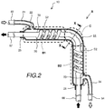
- Fig. 2 is a cross sectional view schematically illustrating, as the first embodiment, the double pipe 10 used as the internal heat exchanger 5 in Fig. 1 .
- the double pipe 10 has an outer pipe 20 made of aluminum alloy and an inner pipe 30, made of aluminum alloy, that is disposed inside the outer pipe 20 and has straight pipe portions B1 and B2 and a bent portion C.
- the bent portion C is configured so that the inner pipe 30 does not make contact with the outer pipe 20 or the inner pipe 30 makes contact with the outer pipe 20 at one point in a radial direction.
- the only one bent portion C is present and the bent portion C has substantially a right angle in the first embodiment, the number of the bent portions C and the angle are not particularly limited in the invention.
- the space between the outer pipe 20 and the inner pipe 30 is the high pressure cooling medium passage 51 through which a high pressure cooling medium passes and the inside of the inner pipe 30 is the low pressure cooling medium passage 52 through which a low pressure cooling medium passes.
- the outer pipe 20 includes an input hole 22 through which the high pressure cooling medium flows in and a high pressure cooling medium lead-in pipe 21, connected to the pipe 63, that guides the high pressure cooling medium to the input hole 22.
- the outer pipe 20 further includes an output hole 23 through which the high pressure cooling medium flows out and a high pressure cooling medium lead-out pipe 24 guiding the high pressure cooling medium led out of the output hole 23 to the pipe 64.
- the outer peripheries of the inner pipe 30 are sealed by sealing portions 25 and 26.
- a spiral groove S2 is formed in each of the straight pipe portions B1 and B2. This causes the high pressure cooling medium flowing through the high pressure cooling medium passage 51 to flow while spirally rotating and part of the low pressure cooling medium flowing through the low pressure cooling medium passage 52 to flow while spirally rotating, thereby achieving efficient heat exchange.
- the high pressure cooling medium travels while rotating counterclockwise with respect to the travel direction.
- the spiral groove S2 preferably makes contact with the inner peripheral surface of the outer pipe 20 as illustrated in Fig. 2 or substantially makes contact with the inner peripheral surface. This prevents the high pressure cooling medium from being short-circuited in the direction in which the double pipe 10 extends, thereby obtaining high heat exchange efficiency.
- the high pressure cooling medium and the low pressure cooling medium as the cooling medium flow in mutually opposite directions.
- Fig. 3 illustrates the bent portion in the first embodiment
- Fig. 3A is a diagram seen from arrow A in Fig. 2
- Fig. 3B is a cross sectional view of range C in Fig. 2
- Fig. 3C is a cross sectional view taken along line X-X in Fig. 2 .
- the outer pipe 20 and the inner pipe 30 are flattened in the bent portion and the flatness is high (further flattened) particularly on the outer bent side (upper side in the drawing).
- Figs. 3 illustrates the bent portion in the first embodiment
- Fig. 3A is a diagram seen from arrow A in Fig. 2
- Fig. 3B is a cross sectional view of range C in Fig. 2
- Fig. 3C is a cross sectional view taken along line X-X in Fig. 2 .
- the outer pipe 20 and the inner pipe 30 are flattened in the bent portion and the flatness is high (further flattened) particularly on the outer
- ribs R1 are concave on the outside of the bent portion and extend in a direction substantially orthogonal to the direction in which the inner pipe 30 extends.
- a rib length LR1 of the ribs R1 is preferably smaller than, but substantially equal to a width LIN of the inner pipe 30. Even when the pressure of the high pressure cooling medium flowing through the high pressure cooling medium passage 51 is applied to the flattened portion, the pressure is received by the ribs R1. The pressure is transferred to the left and right sides of the inner pipe 30 in Fig. 3C to prevent the inner pipe 30 from being broken by the pressure of the high pressure cooling medium.
- the ribs R1 may be convex on the outside of the bent portion and may extend in a direction substantially orthogonal to the direction in which the inner pipe 30 extends. The direction in which the ribs R1 are formed is selected as appropriate.
- the plurality of ribs R1 are preferably formed to improve the proof strength against the pressure.
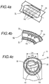
- Fig. 4A is a diagram seen from arrow A in Fig. 2
- Fig. 4B is a cross sectional view illustrating range C in Fig. 2
- Fig. 4C is a cross sectional view taken along line X-X in Fig. 2 .
- the outer pipe 20 and the inner pipe 30 are flattened in the bent portion and the flatness is high (further flattened) particularly in the outer bent side (upper side in the drawing).
- ribs R2 are concave on the outside of the bent portion and extend obliquely with respect to the direction in which the inner pipe 30 extends.
- a rib length LR2 of the ribs R2 is preferably smaller than, but substantially equal to the width LIN of the inner pipe 30. After receiving the pressure, the ribs R2 transfer the pressure to the left and right sides of the inner pipe 30 in Fig. 4C . In addition, since the plurality of ribs R2 are formed, the received pressure can be distributed along the direction in which the inner pipe 30 extends. As a result, it is possible to prevent the inner pipe 30 from being broken by the pressure of the high pressure cooling medium.
- the ribs R2 may be concave on the outside of the bent portion and may extend in a direction substantially orthogonal to the direction in which the inner pipe 30 extends. The direction in which the ribs R2 are formed is selected as appropriate.
- Fig. 5A is a diagram seen from arrow A in Fig. 2
- Fig. 5B is a cross sectional view illustrating range C in Fig. 2
- Fig. 5C is a cross sectional view taken along line X-X in Fig. 2 .
- the outer pipe 20 and the inner pipe 30 are flattened in the bent portion and the flatness is high (further flattened) particularly on the outer bent side (upper side in the drawing).
- Figs. 5A is a diagram seen from arrow A in Fig. 2
- Fig. 5B is a cross sectional view illustrating range C in Fig. 2
- Fig. 5C is a cross sectional view taken along line X-X in Fig. 2 .
- the outer pipe 20 and the inner pipe 30 are flattened in the bent portion and the flatness is high (further flattened) particularly on the outer bent side (upper side in the drawing).
- the ribs R2 are concave on the outside of the bent portion and extend obliquely with respect to the direction in which the inner pipe 30 extends.
- the ribs R2 are formed as part of a spiral groove S1 (first spiral groove) in the third embodiment.
- the ribs R2 transfer the pressure to the left and right sides of the inner pipe 30 in Fig. 5C .
- the pressure received by the ribs R2 can be distributed in the direction in which the inner pipe 30 extends via the spiral groove S1. As a result, it is possible to prevent the inner pipe 30 from being broken by the pressure of the high pressure cooling medium.
- the high pressure cooling medium travels while rotating counterclockwise with respect to the travel direction.
- This rotation direction is the same as that of the high pressure cooling medium flowing through the spiral grooves S2 formed in the straight pipe portions B1 and B2 illustrated in Fig. 2 .
- the rotation direction (rotation direction of the spiral groove S1 with respect to the direction in which the inner pipe 30 extends) of the spiral groove S1 illustrated in the third embodiment is preferably the same as the rotation direction of the spiral grooves S2 (second spiral grooves) of the straight pipe portions B1 and B2.
- An increase in the passage resistance can be suppressed by making the flow direction (that is, the rotation direction of the spiral) of the high pressure cooling medium in the straight pipe portions identical to the flow direction (that is, the rotation direction of the spiral) of the high pressure cooling medium in the bent portion.
- Fig. 6A is a diagram seen from arrow A in Fig. 2
- Fig. 6B is a cross sectional view illustrating range C in Fig. 2
- Fig. 6C is a cross sectional view taken along line X-X in Fig. 2 .
- the outer pipe 20 and the inner pipe 30 are flattened in the bent portion and the flatness is high (further flattened) particularly in the outer bent side (upper side in the drawing).
- Figs. 6A is a diagram seen from arrow A in Fig. 2
- Fig. 6B is a cross sectional view illustrating range C in Fig. 2
- Fig. 6C is a cross sectional view taken along line X-X in Fig. 2 .
- the outer pipe 20 and the inner pipe 30 are flattened in the bent portion and the flatness is high (further flattened) particularly in the outer bent side (upper side in the drawing).
- a rib R3 is concave on the outside of the bent portion and extends along the direction in which the inner pipe 30 extends. After receiving the pressure of the high pressure cooling medium, the rib R3 can distribute the pressure across a length LR3 of the rib R3 in the direction in which the inner pipe 30 extends. As a result, it is possible to prevent the inner pipe 30 from being broken by the pressure of the high pressure cooling medium.
- the rib R3 may be convex on the outside of the bent portion and may extend in a direction substantially orthogonal to the direction in which the inner pipe 30 extends. The direction in which the rib R3 is formed is selected as appropriate.
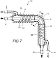
- Fig. 7 is a cross sectional view schematically illustrating a double pipe 100 used to describe the related art.
- the double pipe 100 has an outer pipe 200 made of aluminum alloy and an inner pipe 300, made of aluminum alloy, that is disposed inside the outer pipe 200 and has straight pipe portions B1' and B2' and a bent portion C'.
- the bent portion C' is configured so that the inner pipe 300 does not make contact with the outer pipe 200 or the inner pipe 300 makes contact with the outer pipe 200 at one point in the radial direction.
- the space between the outer pipe 200 and the inner pipe 300 is the high pressure cooling medium passage 51 through which a high pressure cooling medium passes and the inside of the inner pipe 300 is the low pressure cooling medium passage 52 through which a low pressure cooling medium passes.
- Fig. 8A is a cross sectional view taken along line Y-Y in Fig. 7 and Fig. 8B is a cross sectional view illustrating the state of the double pipe broken by the high pressure cooling medium.
- the outer pipe 200 and the inner pipe 300 are flattened in the bent portion and the flatness is high (further flattened) particularly on the outer bent side (upper side in the drawing) .
- pressure Ph of the high pressure cooling medium is applied to the flattened part of the inner pipe 300.
- the inner pipe 300 receives a force so as to be crashed since there is a difference between the pressures. Since the inner pipe 300 does not have ribs unlike the invention, a portion having the higher flatness is first crashed inside as illustrated in Fig. 8B , possibly generating a damaged portion D. A breakage such as the damaged portion D causes a short circuit between the high pressure cooling medium passage 51 and the low pressure cooling medium passage 52, which should be separated from each other, so the cooling medium discharged from the compressor 2 returns to the compressor 2 without passing through the expansion device 6 and the evaporator 7 and the refrigeration cycle 1 cannot provide the normal cooling capability.
- the in-vehicle air conditioner according to the invention can be manufactured industrially and treated as the target of business transaction, the in-vehicle air conditioner has economic value and can be utilized industrially.
Landscapes
- Engineering & Computer Science (AREA)
- Physics & Mathematics (AREA)
- Thermal Sciences (AREA)
- Mechanical Engineering (AREA)
- General Engineering & Computer Science (AREA)
- Geometry (AREA)
- Heat-Exchange Devices With Radiators And Conduit Assemblies (AREA)
Abstract
Description
- The present invention relates to a double pipe used as an internal heat exchanger of a refrigeration cycle to be mounted in a vehicle.
- There is a known technique that uses a double pipe disclosed in, for example,
Patent Literature 1,Patent Literature 2 as an internal heat exchanger for heat exchange between a high pressure medium and a low pressure medium to improve the refrigeration efficiency of a refrigeration cycle. - The double pipes disclosed in
Patent Literature 1 andPatent Literature 2 have an outer pipe and an inner pipe inserted into the outer pipe and perform heat exchange between a high pressure medium flowing through the passage between the outer pipe and the inner pipe and a low pressure medium flowing through the inner pipe. - In insertion of the inner pipe into the outer pipe, the inner pipe having an outer diameter smaller than an inner diameter of the outer pipe is used. When, for example, vibrations of the vehicle are transferred to the double pipe, however, the outer pipe and the inner pipe vibrate individually and make contact with each other, possibly generating abnormal sound or damaging the outer pipe or the inner pipe.
- Therefore, in
Patent Literature 1, the double pipe is configured so as to have a straight pipe portion and bent portions disposed on both sides of the straight pipe portion. In the straight pipe portion, the outer surface (outer periphery) of the inner pipe does not make contact with the inner surface (inner periphery) of the outer pipe or the outer surface of the inner pipe makes contact with the inner surface of the outer pipe only on one side. In the bent portions, the cross sections of the outer pipe and the inner pipe are flattened and the inner peripheral surface of the outer pipe makes contact with the outer peripheral surface of the inner pipe in radial directions. The double pipe has such a structure to fix the outer pipe and the inner pipe. - However, since the outer pipe and the inner pipe are flattened while being brought into contact with each other, the passage between the outer pipe and the inner pipe through which a high pressure medium passes is also deformed by a bending process. In particular, the outer bent sides of the outer pipe and the inner pipe are stretched and brought into substantially close contact with each other, making it difficult to obtain a sufficient passage.
- Accordingly,
Patent Literature 1 has the structure in which the outer surface (outer periphery) of the inner pipe and the inner surface (inner periphery) of the outer pipe are fixed by bringing the outer and inner surfaces into contact with each other at a plurality of points in a radial direction in the straight pipe portion and, in the bent portion, a sufficient space is provided for the outer pipe and the inner pipe so that these pipes do not make contact with each other even when the pipes are bent and flattened or the pipes make contact with each other only at one point in the radial direction. As a result, it is possible to obtain the passage between the outer pipe and the inner pipe through which the high pressure medium passes, thereby suppressing an increase in the passage resistance. - Patent Literature 1 :
JP-A-2006-162241 - Patent Literature 2 :
JP-A-2013-113525 - When a high pressure medium passes through the passage between the outer pipe and the inner pipe, the outer pipe is pressurized so as to expand in the radial direction and the inner pipe is pressurized so as to be crushed in the radial direction. As a result, since the outer pipe is deformed by the pressure of the medium so as to have a perfect-circular cross section regardless of its cross sectional shape, high pressure strength can be easily obtained. In contrast, since the inner pipe is flattened also in the bent portion indicated in
Patent Literature 2, the flattened part is crushed by the pressure of the high pressure medium, making it difficult to obtain sufficient pressure strength. - An object of the invention is to provide a double pipe that suppresses an increase in the passage resistance and has high pressure strength in bent portions.
- According to the invention, there is provided a double pipe (10) used as an internal heat exchanger (5) of a refrigeration cycle (1) to be mounted in a vehicle, the double pipe including an outer pipe (20) and an inner pipe (30) disposed on an inner side of the outer pipe, in which, in a bent portion (C) in which the outer pipe and the inner pipe are bent, the inner pipe does not make contact with the outer pipe or the inner pipe makes contact with the outer pipe at one point in a radial direction, and in which a convex and/or concave rib (R1, R2, R3) having a predetermined length is formed in an outer bent portion of the inner pipe (first aspect). A high pressure medium passes through the passage between the outer pipe and the inner pipe and a low pressure medium passes through the inner pipe for heat exchange.
- In the double pipe according to the invention, the rib preferably extends in a direction substantially orthogonal to a direction in which the inner pipe extends (second aspect). The rib can receive a pressure in a direction in which the inner pipe is crushed and transfer the pressure to the inner pipe, thereby improving the proof strength.
- In the double pipe according to the invention, the rib preferably extends obliquely with respect to a direction in which the inner pipe extends (third aspect). The rib can receive a pressure in a direction in which the inner pipe is crushed, transfer the pressure to the inner pipe, and distribute the pressure in the direction in which the inner pipe extends, thereby improving the proof strength.
- In the double pipe according to the invention, the rib is preferably part of a first groove (S1) extending spirally with respect to the direction in which the inner pipe extends (fourth aspect). The rib can receive a pressure in a direction in which the inner pipe is crushed, transfer the pressure to the inner pipe, and distribute the pressure more surely in the direction in which the inner pipe extends, thereby improving the proof strength.
- In the double pipe according to the invention, the inner pipe preferably has, in a straight pipe portion in which the outer pipe and the inner pipe are not bent, a second groove (S2) extending spirally with respect to the direction in which the inner pipe extends, and in which a direction in which the first groove extends spirally is preferably the same as a direction in which the second groove extends spirally (fifth aspect). By making the direction (that is, the spiral rotation direction) in which the high pressure cooling medium flows in the straight pipe portion identical to the direction (that is, the spiral rotation direction) in which the high pressure cooling medium flows in the bent portion, an increase in the passage resistance can be suppressed.
- Since this causes the inner pipe not to make contact with the outer pipe or to make contact with the outer pipe at one point in the radial direction in the bent portion, so that a sufficient passage is obtained between the outer pipe and the inner pipe and an increase in the passage resistance is prevented. In addition, since a convex or concave rib having a predetermined length is formed in the outer bent portion of the inner pipe, the proof strength can be improved against the pressure in which the inner pipe is crushed.
- In the double pipe according to the invention, the rib preferably extends along the direction in which the inner pipe extends (sixth aspect). The rib can receive a pressure in a direction in which the inner pipe is crushed and distribute the pressure in the direction in which the inner pipe extends, thereby improving the proof strength.
- In the double pipe according to the invention, a plurality of the ribs or a plurality of the first grooves is preferably formed in the inner pipe (seventh aspect). The proof strength can be further improved against the pressure in which the inner pipe is crushed.
- According to the invention, it is possible to provide a double pipe that prevents the passage resistance between the outer pipe and the inner pipe from increasing and improves the proof strength against the pressure in which the inner pipe is crashed.
-
-
Fig. 1 is a schematic view illustrating a refrigeration cycle having a double pipe as an internal heat exchanger. -
Fig. 2 is a cross sectional view schematically illustrating a double pipe according to a first embodiment. -
Fig. 3 illustrates a bent portion in the first embodiment,Fig. 3A is a diagram seen from arrow A inFig. 2 ,Fig. 3B is a cross sectional view of range C inFig. 2 , andFig. 3C is a cross sectional view taken along line X-X inFig. 2 . -
Fig. 4 illustrates a bent portion in a second embodiment,Fig. 4A is a diagram seen from arrow A inFig. 2 ,Fig. 4B is a cross sectional view illustrating range C inFig. 2 , andFig. 4C is a cross sectional view taken along line X-X inFig. 2 . -
Fig. 5 illustrates a bent portion in a third embodiment,Fig. 5A is a diagram seen from arrow A inFig. 2 ,Fig. 5B is a cross sectional view illustrating range C inFig. 2 , andFig. 5C is a cross sectional view taken along line X-X inFig. 2 . -
Fig. 6 illustrates a bent portion in a fourth embodiment,Fig. 6A is a diagram seen from arrow A inFig. 2 ,Fig. 6B is a cross sectional view illustrating range C inFig. 2 , andFig. 6C is a cross sectional view taken along line X-X inFig. 2 . -
Fig. 7 is a cross sectional view schematically illustrating a double pipe according to the related art. -
Fig. 8 illustrates the bent portion in the related art,Fig. 8A is a cross sectional view taken along line Y-Y inFig. 7 , andFig. 8B is a cross sectional view illustrating the state of the double pipe broken by a high pressure cooling medium. - An aspect of the invention will be described below with reference to the attached drawings. The embodiments described below are examples of the invention and the invention is not limited to the following embodiments. Components having the same reference numeral in this specification and the drawings are identical. Various changes are allowed as long as the effects of the invention are obtained.
-
Fig. 1 illustrates an example of arefrigeration cycle 1 having adouble pipe 10 described below. Thisrefrigeration cycle 1 is a part of an in-vehicle air conditioner (not illustrated) to be mounted in a vehicle. - The
refrigeration cycle 1 includes acompressor 2 compressing a cooling medium, acondenser 3 cooling the cooling medium compressed by thecompressor 2, a gas-liquid separator 4 extracting only a liquid cooling medium by performing the gas-liquid separation of the cooling medium cooled by thecondenser 3, anexpansion device 6 expanding the liquid cooling medium by decompressing the liquid cooling medium, and anevaporator 7 evaporating the cooling medium decompressed by theexpansion device 6. Therefrigeration cycle 1 is provided with aninternal heat exchanger 5 including a high pressure coolingmedium passage 51 through which the cooling medium from the gas-liquid separator 4 to theexpansion device 6 passes and a low pressure coolingmedium passage 52 through which the cooling medium from theevaporator 7 to thecompressor 2 passes. Theinternal heat exchanger 5 can reduce the enthalpy of the cooling medium flowing through theevaporator 7 and improve the cooling capacity of therefrigeration cycle 1. - The
refrigeration cycle 1 includes apipe 61 making direct or indirect connection between thecompressor 2 and thecondenser 3, apipe 62 making direct or indirect connection between thecondenser 3 and the gas-liquid separator 4, apipe 63 making direct or indirect connection between the gas-liquid separator 4 and the high pressure coolingmedium passage 51 of theinternal heat exchanger 5, apipe 64 making direct or indirect connection between the high pressure coolingmedium passage 51 of theinternal heat exchanger 5 and theexpansion device 6, apipe 65 making direct or indirect connection between theexpansion device 6 and theevaporator 7, apipe 66 making direct or indirect connection between theevaporator 7 and the low pressure coolingmedium passage 52 of theinternal heat exchanger 5, and apipe 67 making direct or indirect connection between the low pressure coolingmedium passage 52 of theinternal heat exchanger 5 and thecompressor 2 to configure a cycle through which cooling medium is capable of circulating. Although the gas-liquid separator 4 is a component different from thecondenser 3 in this example, the gas-liquid separator 4 may be integrated with thecondenser 3. In addition, although thepipe 65 is provided between theexpansion device 6 and theevaporator 7, theexpansion device 6 may be directly connected to theevaporator 7 by omitting thepipe 65. - When the
compressor 2 is operated in therefrigeration cycle 1 configured as described above, a high-temperature and high-pressure cooling medium is discharged, flows through thecondenser 3, the gas-liquid separator 4, and the high pressure coolingmedium passage 51 of theinternal heat exchanger 5 as indicated by the hollow arrows inFig. 1 , and reaches theexpansion device 6. The cooling medium expanded by theexpansion device 6 becomes a low-temperature and low-pressure cooling medium, flows through theevaporator 7 and the low pressure coolingmedium passage 52 of theinternal heat exchanger 5 as indicated by the solid arrows inFig. 1 , and reaches thecompressor 2 to circulate. -
Fig. 2 is a cross sectional view schematically illustrating, as the first embodiment, thedouble pipe 10 used as theinternal heat exchanger 5 inFig. 1 . Thedouble pipe 10 has anouter pipe 20 made of aluminum alloy and aninner pipe 30, made of aluminum alloy, that is disposed inside theouter pipe 20 and has straight pipe portions B1 and B2 and a bent portion C. The bent portion C is configured so that theinner pipe 30 does not make contact with theouter pipe 20 or theinner pipe 30 makes contact with theouter pipe 20 at one point in a radial direction. Although the only one bent portion C is present and the bent portion C has substantially a right angle in the first embodiment, the number of the bent portions C and the angle are not particularly limited in the invention. The space between theouter pipe 20 and theinner pipe 30 is the high pressure coolingmedium passage 51 through which a high pressure cooling medium passes and the inside of theinner pipe 30 is the low pressure coolingmedium passage 52 through which a low pressure cooling medium passes. - The
outer pipe 20 includes aninput hole 22 through which the high pressure cooling medium flows in and a high pressure cooling medium lead-inpipe 21, connected to thepipe 63, that guides the high pressure cooling medium to theinput hole 22. Theouter pipe 20 further includes anoutput hole 23 through which the high pressure cooling medium flows out and a high pressure cooling medium lead-outpipe 24 guiding the high pressure cooling medium led out of theoutput hole 23 to thepipe 64. In addition, at the ends of theouter pipe 20, the outer peripheries of theinner pipe 30 are sealed by sealingportions - One end of the
inner pipe 30 is connected to thepipe 66 through which the low pressure cooling medium is led in and the other end is connected to thepipe 67 through which the low pressure cooling medium is led out. As illustrated inFig. 2 , a spiral groove S2 is formed in each of the straight pipe portions B1 and B2. This causes the high pressure cooling medium flowing through the high pressure coolingmedium passage 51 to flow while spirally rotating and part of the low pressure cooling medium flowing through the low pressure coolingmedium passage 52 to flow while spirally rotating, thereby achieving efficient heat exchange. In the example inFig. 2 , the high pressure cooling medium travels while rotating counterclockwise with respect to the travel direction. The spiral groove S2 preferably makes contact with the inner peripheral surface of theouter pipe 20 as illustrated inFig. 2 or substantially makes contact with the inner peripheral surface. This prevents the high pressure cooling medium from being short-circuited in the direction in which thedouble pipe 10 extends, thereby obtaining high heat exchange efficiency. - In the
double pipe 10 configured as described above, as illustrated inFig. 2 , the high pressure cooling medium and the low pressure cooling medium as the cooling medium flow in mutually opposite directions. -
Fig. 3 illustrates the bent portion in the first embodiment,Fig. 3A is a diagram seen from arrow A inFig. 2 ,Fig. 3B is a cross sectional view of range C inFig. 2 , andFig. 3C is a cross sectional view taken along line X-X inFig. 2 . As illustrated inFig. 3C , theouter pipe 20 and theinner pipe 30 are flattened in the bent portion and the flatness is high (further flattened) particularly on the outer bent side (upper side in the drawing). In addition, as illustrated inFigs. 3A and 3C , ribs R1 are concave on the outside of the bent portion and extend in a direction substantially orthogonal to the direction in which theinner pipe 30 extends. A rib length LR1 of the ribs R1 is preferably smaller than, but substantially equal to a width LIN of theinner pipe 30. Even when the pressure of the high pressure cooling medium flowing through the high pressure coolingmedium passage 51 is applied to the flattened portion, the pressure is received by the ribs R1. The pressure is transferred to the left and right sides of theinner pipe 30 inFig. 3C to prevent theinner pipe 30 from being broken by the pressure of the high pressure cooling medium. The ribs R1 may be convex on the outside of the bent portion and may extend in a direction substantially orthogonal to the direction in which theinner pipe 30 extends. The direction in which the ribs R1 are formed is selected as appropriate. - In addition, as illustrated in
Figs. 3A and 3B , the plurality of ribs R1 are preferably formed to improve the proof strength against the pressure. - Although the first embodiment of the invention has been described above, the second embodiment will be described below with reference to
Fig. 4 . -
Fig. 4A is a diagram seen from arrow A inFig. 2 ,Fig. 4B is a cross sectional view illustrating range C inFig. 2 , andFig. 4C is a cross sectional view taken along line X-X inFig. 2 . As illustrated inFig. 4C , also in the second embodiment, theouter pipe 20 and theinner pipe 30 are flattened in the bent portion and the flatness is high (further flattened) particularly in the outer bent side (upper side in the drawing). In addition, as illustrated inFigs. 4A, 4B, and 4C , ribs R2 are concave on the outside of the bent portion and extend obliquely with respect to the direction in which theinner pipe 30 extends. A rib length LR2 of the ribs R2 is preferably smaller than, but substantially equal to the width LIN of theinner pipe 30. After receiving the pressure, the ribs R2 transfer the pressure to the left and right sides of theinner pipe 30 inFig. 4C . In addition, since the plurality of ribs R2 are formed, the received pressure can be distributed along the direction in which theinner pipe 30 extends. As a result, it is possible to prevent theinner pipe 30 from being broken by the pressure of the high pressure cooling medium. The ribs R2 may be concave on the outside of the bent portion and may extend in a direction substantially orthogonal to the direction in which theinner pipe 30 extends. The direction in which the ribs R2 are formed is selected as appropriate. - Next, the third embodiment will be described with reference to
Fig. 5. Fig. 5A is a diagram seen from arrow A inFig. 2 ,Fig. 5B is a cross sectional view illustrating range C inFig. 2 , andFig. 5C is a cross sectional view taken along line X-X inFig. 2 . As illustrated inFig. 5C , also in the third embodiment, theouter pipe 20 and theinner pipe 30 are flattened in the bent portion and the flatness is high (further flattened) particularly on the outer bent side (upper side in the drawing). In addition, as illustrated inFigs. 5A, 5B, and 5C , the ribs R2 are concave on the outside of the bent portion and extend obliquely with respect to the direction in which theinner pipe 30 extends. In addition, the ribs R2 are formed as part of a spiral groove S1 (first spiral groove) in the third embodiment. - Accordingly, after receiving the pressure, the ribs R2 transfer the pressure to the left and right sides of the
inner pipe 30 inFig. 5C . In addition, the pressure received by the ribs R2 can be distributed in the direction in which theinner pipe 30 extends via the spiral groove S1. As a result, it is possible to prevent theinner pipe 30 from being broken by the pressure of the high pressure cooling medium. - In the example in
Fig. 5A , the high pressure cooling medium travels while rotating counterclockwise with respect to the travel direction. This rotation direction is the same as that of the high pressure cooling medium flowing through the spiral grooves S2 formed in the straight pipe portions B1 and B2 illustrated inFig. 2 . As described above, the rotation direction (rotation direction of the spiral groove S1 with respect to the direction in which theinner pipe 30 extends) of the spiral groove S1 illustrated in the third embodiment is preferably the same as the rotation direction of the spiral grooves S2 (second spiral grooves) of the straight pipe portions B1 and B2. An increase in the passage resistance can be suppressed by making the flow direction (that is, the rotation direction of the spiral) of the high pressure cooling medium in the straight pipe portions identical to the flow direction (that is, the rotation direction of the spiral) of the high pressure cooling medium in the bent portion. - Next, the fourth embodiment will be described with reference to
Fig. 6. Fig. 6A is a diagram seen from arrow A inFig. 2 ,Fig. 6B is a cross sectional view illustrating range C inFig. 2 , andFig. 6C is a cross sectional view taken along line X-X inFig. 2 . As illustrated inFig. 6C , also in the fourth embodiment, theouter pipe 20 and theinner pipe 30 are flattened in the bent portion and the flatness is high (further flattened) particularly in the outer bent side (upper side in the drawing). In addition, as illustrated inFigs. 6A, 6B, and 6C , a rib R3 is concave on the outside of the bent portion and extends along the direction in which theinner pipe 30 extends. After receiving the pressure of the high pressure cooling medium, the rib R3 can distribute the pressure across a length LR3 of the rib R3 in the direction in which theinner pipe 30 extends. As a result, it is possible to prevent theinner pipe 30 from being broken by the pressure of the high pressure cooling medium. The rib R3 may be convex on the outside of the bent portion and may extend in a direction substantially orthogonal to the direction in which theinner pipe 30 extends. The direction in which the rib R3 is formed is selected as appropriate. - Although four embodiments of the invention have been described above, the case in which the invention is not practiced will be described as a technique to be compared with the invention.
-
Fig. 7 is a cross sectional view schematically illustrating adouble pipe 100 used to describe the related art. Thedouble pipe 100 has anouter pipe 200 made of aluminum alloy and aninner pipe 300, made of aluminum alloy, that is disposed inside theouter pipe 200 and has straight pipe portions B1' and B2' and a bent portion C'. The bent portion C' is configured so that theinner pipe 300 does not make contact with theouter pipe 200 or theinner pipe 300 makes contact with theouter pipe 200 at one point in the radial direction. The space between theouter pipe 200 and theinner pipe 300 is the high pressure coolingmedium passage 51 through which a high pressure cooling medium passes and the inside of theinner pipe 300 is the low pressure coolingmedium passage 52 through which a low pressure cooling medium passes. -
Fig. 8A is a cross sectional view taken along line Y-Y inFig. 7 andFig. 8B is a cross sectional view illustrating the state of the double pipe broken by the high pressure cooling medium. As illustrated inFig. 8A , also in the related art, theouter pipe 200 and theinner pipe 300 are flattened in the bent portion and the flatness is high (further flattened) particularly on the outer bent side (upper side in the drawing) . When the high pressure cooling medium passes through the high pressure coolingmedium passage 51, pressure Ph of the high pressure cooling medium is applied to the flattened part of theinner pipe 300. Although the low pressure cooling medium passes through the low pressure coolingmedium passage 52 at this time, theinner pipe 300 receives a force so as to be crashed since there is a difference between the pressures. Since theinner pipe 300 does not have ribs unlike the invention, a portion having the higher flatness is first crashed inside as illustrated inFig. 8B , possibly generating a damaged portion D. A breakage such as the damaged portion D causes a short circuit between the high pressure coolingmedium passage 51 and the low pressure coolingmedium passage 52, which should be separated from each other, so the cooling medium discharged from thecompressor 2 returns to thecompressor 2 without passing through theexpansion device 6 and theevaporator 7 and therefrigeration cycle 1 cannot provide the normal cooling capability. - Since the in-vehicle air conditioner according to the invention can be manufactured industrially and treated as the target of business transaction, the in-vehicle air conditioner has economic value and can be utilized industrially.
-
- 1:
- refrigeration cycle
- 2:
- compressor
- 3:
- condenser
- 4:
- gas-liquid separator
- 5:
- internal heat exchanger
- 6:
- expansion device
- 7:
- evaporator
- 10:
- double pipe
- 20:
- outer pipe
- 21:
- high pressure cooling medium lead-in pipe
- 22:
- input hole
- 23:
- output hole
- 24:
- high pressure cooling medium lead-out pipe
- 25:
- sealing portion
- 26:
- sealing portion
- 30:
- inner pipe
- 51:
- high pressure cooling medium passage
- 52:
- low pressure cooling medium passage
- 61, 62, 63, 64, 65, 66, 67:
- pipe
- 100:
- double pipe
- 200:
- outer pipe
- 300:
- inner pipe
- B1, B2, B1', B2':
- straight pipe portion
- C, C':
- bent portion
- D:
- damaged portion
- R1:
- rib
- R2:
- rib
- R3:
- rib
- S1:
- spiral groove (first spiral groove)
- S2:
- spiral groove (second spiral groove)
- LR1:
- rib length
- LR2:
- rib length
- LR3:
- rib length
- LIN:
- width of inner pipe
- Ph:
- pressure of high pressure cooling medium
Claims (7)
- A double pipe (10) used as an internal heat exchanger (5) of a refrigeration cycle (1) to be mounted in a vehicle, the double pipe comprising:an outer pipe (20); andan inner pipe (30) disposed on an inner side of the outer pipe,wherein, in a bent portion (C) in which the outer pipe and the inner pipe are bent, the inner pipe does not make contact with the outer pipe or the inner pipe makes contact with the outer pipe at one point in a radial direction,characterized in that a convex and/or concave rib (R1, R2, R3) having a predetermined length is formed in an outer bent portion of the inner pipe.
- The double pipe according to claim 1,
wherein the rib (R1) extends in a direction substantially orthogonal to a direction in which the inner pipe extends. - The double pipe according to claim 1,
wherein the rib (R2) extends obliquely with respect to a direction in which the inner pipe extends. - The double pipe according to any one of claims 1 to 3,
wherein the rib (R2) is part of a first groove (S1) extending spirally with respect to the direction in which the inner pipe extends. - The double pipe according to claim 4,
wherein the inner pipe has, in a straight pipe portion in which the outer pipe and the inner pipe are not bent, a second groove (S2) extending spirally with respect to the direction in which the inner pipe extends, and
wherein a direction in which the first groove extends spirally is the same as a direction in which the second groove extends spirally. - The double pipe according to claim 1,
wherein the rib (R3) extends along a direction in which the inner pipe extends. - The double pipe according to any one of claims 1 to 6,
wherein a plurality of the ribs or a plurality of the first grooves is formed in the inner pipe.
Applications Claiming Priority (1)
| Application Number | Priority Date | Filing Date | Title |
|---|---|---|---|
| JP2016089790A JP2017198392A (en) | 2016-04-27 | 2016-04-27 | Double tube |
Publications (1)
| Publication Number | Publication Date |
|---|---|
| EP3239638A1 true EP3239638A1 (en) | 2017-11-01 |
Family
ID=58664512
Family Applications (1)
| Application Number | Title | Priority Date | Filing Date |
|---|---|---|---|
| EP17168237.0A Withdrawn EP3239638A1 (en) | 2016-04-27 | 2017-04-26 | Double pipe |
Country Status (3)
| Country | Link |
|---|---|
| EP (1) | EP3239638A1 (en) |
| JP (1) | JP2017198392A (en) |
| CN (1) | CN107421164A (en) |
Cited By (2)
| Publication number | Priority date | Publication date | Assignee | Title |
|---|---|---|---|---|
| EP3722723A1 (en) * | 2019-04-08 | 2020-10-14 | Hamilton Sundstrand Corporation | Curved heat exchanger |
| US20220290925A1 (en) * | 2019-10-23 | 2022-09-15 | Uacj Corporation | Heat-transferring double pipe, inner pipe for heat-transferring double pipe, and manufacturing method thereof |
Families Citing this family (6)
| Publication number | Priority date | Publication date | Assignee | Title |
|---|---|---|---|---|
| KR102403434B1 (en) * | 2017-08-18 | 2022-05-27 | 조한용 | Double wall pipe |
| JP2020012619A (en) * | 2018-07-20 | 2020-01-23 | 株式会社ヴァレオジャパン | Double-pipe heat exchanger |
| CN109282675B (en) * | 2018-08-23 | 2020-02-14 | 常州市盛士达汽车空调有限公司 | Sleeve type heat exchanger, method and mold for manufacturing same |
| CN110285600B (en) * | 2019-05-15 | 2021-12-17 | 中国电子科技集团公司第十一研究所 | J-T refrigerator using double-layer fin type heat exchanger |
| CN114791234B (en) * | 2022-04-21 | 2024-06-21 | 桂林电子科技大学 | A shell and tube variable volume coaxial tube heat exchanger |
| CN119215437B (en) * | 2024-11-28 | 2025-04-01 | 福大紫金氢能科技股份有限公司 | Sleeve type ammonia gas-liquid separator and system for ammonia decomposition reaction |
Citations (8)
| Publication number | Priority date | Publication date | Assignee | Title |
|---|---|---|---|---|
| EP1096131A1 (en) * | 1999-10-26 | 2001-05-02 | Senior Flexonics Automotive Limited | Exhaust gas recirculation cooler |
| EP1136780A2 (en) * | 2000-03-23 | 2001-09-26 | Senior Investments AG | Pipe within pipe heat exchanger construction |
| JP2005055064A (en) * | 2003-08-04 | 2005-03-03 | Toyo Radiator Co Ltd | Double tube-type heat exchanger and its manufacturing method |
| US20060096314A1 (en) * | 2004-11-09 | 2006-05-11 | Denso Corporation | Double-wall pipe and refrigerant cycle device using the same |
| JP2006162241A (en) | 2004-11-09 | 2006-06-22 | Denso Corp | Double tube, manufacturing method thereof, and refrigeration cycle apparatus including the same |
| GB2451862A (en) * | 2007-08-15 | 2009-02-18 | Senior Uk Ltd | High gas inlet temperature EGR system |
| WO2009034833A1 (en) * | 2007-09-10 | 2009-03-19 | Usui Kokusai Sangyo Kaisha Limited | Urea water piping structure for exhaust purification device for internal combustion engine |
| JP2013113525A (en) | 2011-11-30 | 2013-06-10 | Watanabe Seisakusho:Kk | Double pipe |
Family Cites Families (23)
| Publication number | Priority date | Publication date | Assignee | Title |
|---|---|---|---|---|
| CH327455A (en) * | 1954-10-06 | 1958-01-31 | Frigotherm Ag | Heat exchanger |
| JPS53144525U (en) * | 1977-04-21 | 1978-11-14 | ||
| JPS541255U (en) * | 1977-06-07 | 1979-01-06 | ||
| JPS602180U (en) * | 1983-06-17 | 1985-01-09 | 日本鉱業株式会社 | Double tube type heat transfer tube |
| JP2000111277A (en) * | 1998-10-09 | 2000-04-18 | Toyota Motor Corp | Double-pipe heat exchanger |
| JP2002013882A (en) * | 2000-06-30 | 2002-01-18 | Matsushita Refrig Co Ltd | Double pipe heat exchanger and refrigerating cycle device using it |
| JP4744746B2 (en) * | 2001-09-06 | 2011-08-10 | 臼井国際産業株式会社 | Heat transfer tube and multi-tube heat exchanger using this heat transfer tube and radiator built-in oil cooler |
| JP2006132905A (en) * | 2004-11-09 | 2006-05-25 | Denso Corp | Refrigeration cycle |
| JP4350058B2 (en) * | 2004-11-09 | 2009-10-21 | 株式会社デンソー | Double pipe for refrigerant |
| JP2007032949A (en) * | 2005-07-28 | 2007-02-08 | Showa Denko Kk | Heat exchanger |
| JP2007101151A (en) * | 2005-10-07 | 2007-04-19 | Matsushita Electric Ind Co Ltd | Heat exchanger |
| JP4698417B2 (en) * | 2005-12-28 | 2011-06-08 | 株式会社デンソー | Manufacturing method of double pipe |
| JP2009270802A (en) * | 2008-04-08 | 2009-11-19 | Tgk Co Ltd | Internal heat exchanger |
| JP2011191034A (en) * | 2010-03-16 | 2011-09-29 | Showa Denko Kk | Dual-pipe heat exchanger |
| KR101600296B1 (en) * | 2010-08-18 | 2016-03-07 | 한온시스템 주식회사 | Double pipe heat exchanger and manufacturing method the same |
| JP5556644B2 (en) * | 2010-12-17 | 2014-07-23 | 株式会社デンソー | Multi-tube heat exchanger |
| DE102011100683A1 (en) * | 2011-05-06 | 2012-11-08 | GM Global Technology Operations LLC (n. d. Gesetzen des Staates Delaware) | Heat exchanger for a motor vehicle air conditioning |
| JP6172950B2 (en) * | 2012-02-01 | 2017-08-02 | 株式会社Uacj | Double tube for heat exchanger |
| KR101925551B1 (en) * | 2012-02-29 | 2018-12-05 | 한온시스템 주식회사 | Cooling system of air conditioning apparatus for vehicles |
| GB2508842A (en) * | 2012-12-12 | 2014-06-18 | Eaton Ind Ip Gmbh & Co Kg | Double wall tube heat exchanger |
| KR20150010826A (en) * | 2013-07-18 | 2015-01-29 | 삼성전자주식회사 | Air conditioner and double pipe heat exchanger |
| KR101415738B1 (en) * | 2013-08-07 | 2014-07-09 | 주식회사 두원공조 | Liquid supercooling system |
| GB2523107A (en) * | 2014-02-12 | 2015-08-19 | Eaton Ind Ip Gmbh & Co Kg | Heat exchanger |
-
2016
- 2016-04-27 JP JP2016089790A patent/JP2017198392A/en active Pending
-
2017
- 2017-04-24 CN CN201710270833.3A patent/CN107421164A/en active Pending
- 2017-04-26 EP EP17168237.0A patent/EP3239638A1/en not_active Withdrawn
Patent Citations (8)
| Publication number | Priority date | Publication date | Assignee | Title |
|---|---|---|---|---|
| EP1096131A1 (en) * | 1999-10-26 | 2001-05-02 | Senior Flexonics Automotive Limited | Exhaust gas recirculation cooler |
| EP1136780A2 (en) * | 2000-03-23 | 2001-09-26 | Senior Investments AG | Pipe within pipe heat exchanger construction |
| JP2005055064A (en) * | 2003-08-04 | 2005-03-03 | Toyo Radiator Co Ltd | Double tube-type heat exchanger and its manufacturing method |
| US20060096314A1 (en) * | 2004-11-09 | 2006-05-11 | Denso Corporation | Double-wall pipe and refrigerant cycle device using the same |
| JP2006162241A (en) | 2004-11-09 | 2006-06-22 | Denso Corp | Double tube, manufacturing method thereof, and refrigeration cycle apparatus including the same |
| GB2451862A (en) * | 2007-08-15 | 2009-02-18 | Senior Uk Ltd | High gas inlet temperature EGR system |
| WO2009034833A1 (en) * | 2007-09-10 | 2009-03-19 | Usui Kokusai Sangyo Kaisha Limited | Urea water piping structure for exhaust purification device for internal combustion engine |
| JP2013113525A (en) | 2011-11-30 | 2013-06-10 | Watanabe Seisakusho:Kk | Double pipe |
Cited By (4)
| Publication number | Priority date | Publication date | Assignee | Title |
|---|---|---|---|---|
| EP3722723A1 (en) * | 2019-04-08 | 2020-10-14 | Hamilton Sundstrand Corporation | Curved heat exchanger |
| US20220290925A1 (en) * | 2019-10-23 | 2022-09-15 | Uacj Corporation | Heat-transferring double pipe, inner pipe for heat-transferring double pipe, and manufacturing method thereof |
| US12203709B2 (en) * | 2019-10-23 | 2025-01-21 | Uacj Corporation | Heat-transferring double pipe, inner pipe for heat-transferring double pipe, and manufacturing method thereof |
| EP4006475B1 (en) * | 2019-10-23 | 2025-11-26 | UACJ Corporation | Heat transfer double pipe and method for manufacturing same |
Also Published As
| Publication number | Publication date |
|---|---|
| JP2017198392A (en) | 2017-11-02 |
| CN107421164A (en) | 2017-12-01 |
Similar Documents
| Publication | Publication Date | Title |
|---|---|---|
| US6928833B2 (en) | Finned tube for heat exchangers, heat exchanger, process for producing heat exchanger finned tube, and process for fabricating heat exchanger | |
| JP2017198392A (en) | Double tube | |
| JP5202030B2 (en) | Double tube heat exchanger | |
| US8590604B2 (en) | Double-wall-tube heat exchanger | |
| EP3614074B1 (en) | Double-pipe eat exchanger | |
| JP2009162395A (en) | Double-wall-tube heat exchanger | |
| JP5452367B2 (en) | Gas-liquid separator and refrigeration cycle apparatus | |
| US20080066488A1 (en) | Heat Exchanger, Intermediate Heat Exchanger, and Refrigeration Cycle | |
| JP6823906B1 (en) | Double tube for heat exchanger | |
| US20200248845A1 (en) | Dual pipe | |
| JP2009162396A (en) | Double-wall-tube heat exchanger | |
| JP2007032949A (en) | Heat exchanger | |
| JP5911597B2 (en) | Flat shape heat transfer tube, method of manufacturing cross fin tube type heat exchanger equipped with the same, cross fin tube type heat exchanger manufactured by the method | |
| WO2017038962A1 (en) | Method for manufacturing double pipe | |
| EP1818641A1 (en) | Internally grooved heat transfer tube for high-pressure refrigerant | |
| US20160054037A1 (en) | Refrigeration Device Comprising an Evaporator | |
| JP2009041798A (en) | Heat exchanger | |
| JP2006273049A (en) | Vehicular air conditioner | |
| JP5898892B2 (en) | Intermediate heat exchanger | |
| JP2017026248A (en) | Double-pipe heat exchanger | |
| EP1843109A2 (en) | Cooling System | |
| JP5202029B2 (en) | Double tube heat exchanger | |
| JP2014126284A (en) | Refrigeration device | |
| JP2011033239A (en) | Heat transfer pipe, air conditioner and method for manufacturing the heat transfer pipe | |
| KR20160083440A (en) | Multiple pipe for refrigerator exchanger |
Legal Events
| Date | Code | Title | Description |
|---|---|---|---|
| PUAI | Public reference made under article 153(3) epc to a published international application that has entered the european phase |
Free format text: ORIGINAL CODE: 0009012 |
|
| STAA | Information on the status of an ep patent application or granted ep patent |
Free format text: STATUS: THE APPLICATION HAS BEEN PUBLISHED |
|
| AK | Designated contracting states |
Kind code of ref document: A1 Designated state(s): AL AT BE BG CH CY CZ DE DK EE ES FI FR GB GR HR HU IE IS IT LI LT LU LV MC MK MT NL NO PL PT RO RS SE SI SK SM TR |
|
| AX | Request for extension of the european patent |
Extension state: BA ME |
|
| STAA | Information on the status of an ep patent application or granted ep patent |
Free format text: STATUS: REQUEST FOR EXAMINATION WAS MADE |
|
| 17P | Request for examination filed |
Effective date: 20180419 |
|
| RBV | Designated contracting states (corrected) |
Designated state(s): AL AT BE BG CH CY CZ DE DK EE ES FI FR GB GR HR HU IE IS IT LI LT LU LV MC MK MT NL NO PL PT RO RS SE SI SK SM TR |
|
| STAA | Information on the status of an ep patent application or granted ep patent |
Free format text: STATUS: EXAMINATION IS IN PROGRESS |
|
| 17Q | First examination report despatched |
Effective date: 20210531 |
|
| STAA | Information on the status of an ep patent application or granted ep patent |
Free format text: STATUS: THE APPLICATION IS DEEMED TO BE WITHDRAWN |
|
| 18D | Application deemed to be withdrawn |
Effective date: 20211012 |