EP3239614A1 - Systems and methods of predicting physical parameters for a combustion fuel system - Google Patents
Systems and methods of predicting physical parameters for a combustion fuel system Download PDFInfo
- Publication number
- EP3239614A1 EP3239614A1 EP17153469.6A EP17153469A EP3239614A1 EP 3239614 A1 EP3239614 A1 EP 3239614A1 EP 17153469 A EP17153469 A EP 17153469A EP 3239614 A1 EP3239614 A1 EP 3239614A1
- Authority
- EP
- European Patent Office
- Prior art keywords
- fuel system
- water injection
- liquid fuel
- physical parameter
- partially
- Prior art date
- Legal status (The legal status is an assumption and is not a legal conclusion. Google has not performed a legal analysis and makes no representation as to the accuracy of the status listed.)
- Withdrawn
Links
- 239000000446 fuel Substances 0.000 title claims abstract description 213
- 238000000034 method Methods 0.000 title claims abstract description 47
- 238000002485 combustion reaction Methods 0.000 title abstract description 59
- XLYOFNOQVPJJNP-UHFFFAOYSA-N water Substances O XLYOFNOQVPJJNP-UHFFFAOYSA-N 0.000 claims abstract description 75
- 238000002347 injection Methods 0.000 claims abstract description 66
- 239000007924 injection Substances 0.000 claims abstract description 66
- 239000007788 liquid Substances 0.000 claims abstract description 55
- 238000012423 maintenance Methods 0.000 claims description 10
- 238000010926 purge Methods 0.000 claims description 6
- 239000007789 gas Substances 0.000 description 14
- 238000010586 diagram Methods 0.000 description 11
- 238000012545 processing Methods 0.000 description 6
- 238000004891 communication Methods 0.000 description 5
- 238000004590 computer program Methods 0.000 description 5
- 230000002596 correlated effect Effects 0.000 description 4
- 238000010304 firing Methods 0.000 description 4
- 230000006870 function Effects 0.000 description 4
- VNWKTOKETHGBQD-UHFFFAOYSA-N methane Chemical compound C VNWKTOKETHGBQD-UHFFFAOYSA-N 0.000 description 4
- 239000011343 solid material Substances 0.000 description 4
- 230000003044 adaptive effect Effects 0.000 description 3
- 239000006227 byproduct Substances 0.000 description 3
- 230000007423 decrease Effects 0.000 description 3
- 230000003247 decreasing effect Effects 0.000 description 3
- 230000000694 effects Effects 0.000 description 3
- 230000008859 change Effects 0.000 description 2
- 238000005260 corrosion Methods 0.000 description 2
- 230000007797 corrosion Effects 0.000 description 2
- 230000003628 erosive effect Effects 0.000 description 2
- 238000004519 manufacturing process Methods 0.000 description 2
- 238000012986 modification Methods 0.000 description 2
- 230000004048 modification Effects 0.000 description 2
- 239000003345 natural gas Substances 0.000 description 2
- 238000003860 storage Methods 0.000 description 2
- 238000013528 artificial neural network Methods 0.000 description 1
- 230000008901 benefit Effects 0.000 description 1
- 238000004939 coking Methods 0.000 description 1
- 230000001276 controlling effect Effects 0.000 description 1
- 230000009977 dual effect Effects 0.000 description 1
- 238000013213 extrapolation Methods 0.000 description 1
- 230000036541 health Effects 0.000 description 1
- 238000010801 machine learning Methods 0.000 description 1
- 239000000463 material Substances 0.000 description 1
- 239000000203 mixture Substances 0.000 description 1
- 230000008569 process Effects 0.000 description 1
- 230000009467 reduction Effects 0.000 description 1
- 230000025508 response to water Effects 0.000 description 1
- 239000007787 solid Substances 0.000 description 1
- 230000001629 suppression Effects 0.000 description 1
- 238000012546 transfer Methods 0.000 description 1
- 238000011144 upstream manufacturing Methods 0.000 description 1
Images

Classifications
-
- F—MECHANICAL ENGINEERING; LIGHTING; HEATING; WEAPONS; BLASTING
- F01—MACHINES OR ENGINES IN GENERAL; ENGINE PLANTS IN GENERAL; STEAM ENGINES
- F01D—NON-POSITIVE DISPLACEMENT MACHINES OR ENGINES, e.g. STEAM TURBINES
- F01D21/00—Shutting-down of machines or engines, e.g. in emergency; Regulating, controlling, or safety means not otherwise provided for
- F01D21/003—Arrangements for testing or measuring
-
- F—MECHANICAL ENGINEERING; LIGHTING; HEATING; WEAPONS; BLASTING
- F02—COMBUSTION ENGINES; HOT-GAS OR COMBUSTION-PRODUCT ENGINE PLANTS
- F02C—GAS-TURBINE PLANTS; AIR INTAKES FOR JET-PROPULSION PLANTS; CONTROLLING FUEL SUPPLY IN AIR-BREATHING JET-PROPULSION PLANTS
- F02C9/00—Controlling gas-turbine plants; Controlling fuel supply in air- breathing jet-propulsion plants
- F02C9/26—Control of fuel supply
- F02C9/28—Regulating systems responsive to plant or ambient parameters, e.g. temperature, pressure, rotor speed
-
- F—MECHANICAL ENGINEERING; LIGHTING; HEATING; WEAPONS; BLASTING
- F02—COMBUSTION ENGINES; HOT-GAS OR COMBUSTION-PRODUCT ENGINE PLANTS
- F02C—GAS-TURBINE PLANTS; AIR INTAKES FOR JET-PROPULSION PLANTS; CONTROLLING FUEL SUPPLY IN AIR-BREATHING JET-PROPULSION PLANTS
- F02C3/00—Gas-turbine plants characterised by the use of combustion products as the working fluid
- F02C3/20—Gas-turbine plants characterised by the use of combustion products as the working fluid using a special fuel, oxidant, or dilution fluid to generate the combustion products
- F02C3/30—Adding water, steam or other fluids for influencing combustion, e.g. to obtain cleaner exhaust gases
-
- F—MECHANICAL ENGINEERING; LIGHTING; HEATING; WEAPONS; BLASTING
- F02—COMBUSTION ENGINES; HOT-GAS OR COMBUSTION-PRODUCT ENGINE PLANTS
- F02C—GAS-TURBINE PLANTS; AIR INTAKES FOR JET-PROPULSION PLANTS; CONTROLLING FUEL SUPPLY IN AIR-BREATHING JET-PROPULSION PLANTS
- F02C7/00—Features, components parts, details or accessories, not provided for in, or of interest apart form groups F02C1/00 - F02C6/00; Air intakes for jet-propulsion plants
- F02C7/22—Fuel supply systems
-
- F—MECHANICAL ENGINEERING; LIGHTING; HEATING; WEAPONS; BLASTING
- F02—COMBUSTION ENGINES; HOT-GAS OR COMBUSTION-PRODUCT ENGINE PLANTS
- F02C—GAS-TURBINE PLANTS; AIR INTAKES FOR JET-PROPULSION PLANTS; CONTROLLING FUEL SUPPLY IN AIR-BREATHING JET-PROPULSION PLANTS
- F02C7/00—Features, components parts, details or accessories, not provided for in, or of interest apart form groups F02C1/00 - F02C6/00; Air intakes for jet-propulsion plants
- F02C7/22—Fuel supply systems
- F02C7/232—Fuel valves; Draining valves or systems
-
- F—MECHANICAL ENGINEERING; LIGHTING; HEATING; WEAPONS; BLASTING
- F23—COMBUSTION APPARATUS; COMBUSTION PROCESSES
- F23L—SUPPLYING AIR OR NON-COMBUSTIBLE LIQUIDS OR GASES TO COMBUSTION APPARATUS IN GENERAL ; VALVES OR DAMPERS SPECIALLY ADAPTED FOR CONTROLLING AIR SUPPLY OR DRAUGHT IN COMBUSTION APPARATUS; INDUCING DRAUGHT IN COMBUSTION APPARATUS; TOPS FOR CHIMNEYS OR VENTILATING SHAFTS; TERMINALS FOR FLUES
- F23L7/00—Supplying non-combustible liquids or gases, other than air, to the fire, e.g. oxygen, steam
- F23L7/002—Supplying water
-
- F—MECHANICAL ENGINEERING; LIGHTING; HEATING; WEAPONS; BLASTING
- F23—COMBUSTION APPARATUS; COMBUSTION PROCESSES
- F23N—REGULATING OR CONTROLLING COMBUSTION
- F23N5/00—Systems for controlling combustion
- F23N5/02—Systems for controlling combustion using devices responsive to thermal changes or to thermal expansion of a medium
- F23N5/10—Systems for controlling combustion using devices responsive to thermal changes or to thermal expansion of a medium using thermocouples
- F23N5/102—Systems for controlling combustion using devices responsive to thermal changes or to thermal expansion of a medium using thermocouples using electronic means
-
- F—MECHANICAL ENGINEERING; LIGHTING; HEATING; WEAPONS; BLASTING
- F23—COMBUSTION APPARATUS; COMBUSTION PROCESSES
- F23R—GENERATING COMBUSTION PRODUCTS OF HIGH PRESSURE OR HIGH VELOCITY, e.g. GAS-TURBINE COMBUSTION CHAMBERS
- F23R3/00—Continuous combustion chambers using liquid or gaseous fuel
- F23R3/28—Continuous combustion chambers using liquid or gaseous fuel characterised by the fuel supply
- F23R3/36—Supply of different fuels
-
- F—MECHANICAL ENGINEERING; LIGHTING; HEATING; WEAPONS; BLASTING
- F05—INDEXING SCHEMES RELATING TO ENGINES OR PUMPS IN VARIOUS SUBCLASSES OF CLASSES F01-F04
- F05D—INDEXING SCHEME FOR ASPECTS RELATING TO NON-POSITIVE-DISPLACEMENT MACHINES OR ENGINES, GAS-TURBINES OR JET-PROPULSION PLANTS
- F05D2240/00—Components
- F05D2240/35—Combustors or associated equipment
-
- F—MECHANICAL ENGINEERING; LIGHTING; HEATING; WEAPONS; BLASTING
- F05—INDEXING SCHEMES RELATING TO ENGINES OR PUMPS IN VARIOUS SUBCLASSES OF CLASSES F01-F04
- F05D—INDEXING SCHEME FOR ASPECTS RELATING TO NON-POSITIVE-DISPLACEMENT MACHINES OR ENGINES, GAS-TURBINES OR JET-PROPULSION PLANTS
- F05D2260/00—Function
- F05D2260/80—Diagnostics
-
- F—MECHANICAL ENGINEERING; LIGHTING; HEATING; WEAPONS; BLASTING
- F05—INDEXING SCHEMES RELATING TO ENGINES OR PUMPS IN VARIOUS SUBCLASSES OF CLASSES F01-F04
- F05D—INDEXING SCHEME FOR ASPECTS RELATING TO NON-POSITIVE-DISPLACEMENT MACHINES OR ENGINES, GAS-TURBINES OR JET-PROPULSION PLANTS
- F05D2270/00—Control
- F05D2270/01—Purpose of the control system
- F05D2270/16—Purpose of the control system to control water or steam injection
-
- F—MECHANICAL ENGINEERING; LIGHTING; HEATING; WEAPONS; BLASTING
- F05—INDEXING SCHEMES RELATING TO ENGINES OR PUMPS IN VARIOUS SUBCLASSES OF CLASSES F01-F04
- F05D—INDEXING SCHEME FOR ASPECTS RELATING TO NON-POSITIVE-DISPLACEMENT MACHINES OR ENGINES, GAS-TURBINES OR JET-PROPULSION PLANTS
- F05D2270/00—Control
- F05D2270/40—Type of control system
- F05D2270/44—Type of control system active, predictive, or anticipative
-
- F—MECHANICAL ENGINEERING; LIGHTING; HEATING; WEAPONS; BLASTING
- F23—COMBUSTION APPARATUS; COMBUSTION PROCESSES
- F23D—BURNERS
- F23D2900/00—Special features of, or arrangements for burners using fluid fuels or solid fuels suspended in a carrier gas
- F23D2900/14—Special features of gas burners
- F23D2900/14681—Adding steam or water vapor to primary or secondary combustion air
-
- F—MECHANICAL ENGINEERING; LIGHTING; HEATING; WEAPONS; BLASTING
- F23—COMBUSTION APPARATUS; COMBUSTION PROCESSES
- F23N—REGULATING OR CONTROLLING COMBUSTION
- F23N2223/00—Signal processing; Details thereof
- F23N2223/48—Learning / Adaptive control
-
- F—MECHANICAL ENGINEERING; LIGHTING; HEATING; WEAPONS; BLASTING
- F23—COMBUSTION APPARATUS; COMBUSTION PROCESSES
- F23N—REGULATING OR CONTROLLING COMBUSTION
- F23N2237/00—Controlling
- F23N2237/22—Controlling water injection
-
- F—MECHANICAL ENGINEERING; LIGHTING; HEATING; WEAPONS; BLASTING
- F23—COMBUSTION APPARATUS; COMBUSTION PROCESSES
- F23N—REGULATING OR CONTROLLING COMBUSTION
- F23N2241/00—Applications
- F23N2241/20—Gas turbines
-
- F—MECHANICAL ENGINEERING; LIGHTING; HEATING; WEAPONS; BLASTING
- F23—COMBUSTION APPARATUS; COMBUSTION PROCESSES
- F23N—REGULATING OR CONTROLLING COMBUSTION
- F23N2900/00—Special features of, or arrangements for controlling combustion
- F23N2900/05006—Controlling systems using neuronal networks
-
- F—MECHANICAL ENGINEERING; LIGHTING; HEATING; WEAPONS; BLASTING
- F23—COMBUSTION APPARATUS; COMBUSTION PROCESSES
- F23R—GENERATING COMBUSTION PRODUCTS OF HIGH PRESSURE OR HIGH VELOCITY, e.g. GAS-TURBINE COMBUSTION CHAMBERS
- F23R2900/00—Special features of, or arrangements for continuous combustion chambers; Combustion processes therefor
- F23R2900/00005—Preventing fatigue failures or reducing mechanical stress in gas turbine components
-
- F—MECHANICAL ENGINEERING; LIGHTING; HEATING; WEAPONS; BLASTING
- F23—COMBUSTION APPARATUS; COMBUSTION PROCESSES
- F23R—GENERATING COMBUSTION PRODUCTS OF HIGH PRESSURE OR HIGH VELOCITY, e.g. GAS-TURBINE COMBUSTION CHAMBERS
- F23R2900/00—Special features of, or arrangements for continuous combustion chambers; Combustion processes therefor
- F23R2900/00019—Repairing or maintaining combustion chamber liners or subparts
Definitions
- the disclosure relates to the art of turbomachines, and, more particularly, to systems and methods of predicting physical parameters for a combustion fuel system.
- Combustion fuel systems burn gaseous fuel (for example, natural gas). Some combustion fuel systems can burn gaseous fuel and liquid fuel, such as diesel. Typically, a dual fuel combustion system operates using the gaseous fuel, while the liquid fuel is used as a backup fuel when the gaseous fuel is not available due to, for example, issues with delivery of the gaseous fuel to the combustion fuel system.
- gaseous fuel for example, natural gas
- liquid fuel such as diesel
- a combustion chamber of the combustion fuel system can be configured to receive both the gaseous fuel and the liquid fuel.
- Use of liquid fuel may result in by-products or loss of material due to erosion/corrosion, which may degrade flow paths for delivering fuels in the combustor chamber and, as a result, decrease productivity and reliability of the combustion fuel system.
- a method of predicting physical parameters for a fuel system includes causing water injection in at least one combustor.
- the water injection can be associated with at least one time.
- the method can include measuring exhaust temperature spread data associated with the water injection and correlating the exhaust spread data to at least one physical parameter associated with a nozzle or a valve of the fuel system.
- the method can further include storing the exhaust spread data, at least one physical parameter, and at least one time to a database. Historical data can be provided from the database to an analytical model.
- the analytical model can be operable to predict, based at least partially on the stored historical data, at least one future physical parameter associated with a future time.
- the method can predict changes in a productivity of the fuel system. Additionally, the method can issue, based at least partially on the prediction, a maintenance recommendation for the fuel system. Operational adjustments of the fuel system can be performed based at least partially on the prediction.
- At least one water injection is performed at a commissioning of the fuel system.
- the water injection can be performed via at least one pilot valve of at least one pilot nozzle of the fuel system.
- the water injection is performed via at least one main valve or at least one main nozzle of the fuel system.
- physical parameters include a flow rate of at least one nozzle of the fuel system and a cross-section area of at least one valve of the fuel system.
- the water injection is performed while operating on a gas fuel. In certain embodiments, the water injection is performed after a liquid fuel operation.
- the analytical model is operable to provide guidelines or permissive for gas turbines operations, a variation of a fuel flow rate, a firing temperature, or an adjusted water purge duration of the fuel system.
- the exhaust spread data is measured with a set of thermocouples disposed adjacent to an exhaust system associated with the combustor.
- a system for predicting physical parameters of a combustion fuel system can include a combustor.
- the system can further include a processor communicatively coupled to a memory, with the memory storing instructions which, when executed by the processing circuit, perform certain operations.
- These operations can include causing at least one water injection in at least one combustor, the at least one water injection being associated with at least one time; measuring at least one exhaust spread data associated with the at least one water injection; correlating the at least one exhaust spread data with at least one physical parameter associated with at least one of a nozzle or a valve of the liquid fuel system; storing the at least one exhaust spread data, the at least one physical parameter, and the at least one time to a database; and providing stored data from the database to an analytical model, wherein the analytical model is operable to predict, based at least partially on the stored data, at least one future physical parameter associated with a future time.
- Certain embodiments of the disclosure can include systems and methods of predicting physical parameters of a combustion fuel system.
- the disclosed systems and methods may provide diagnostics of fuel nozzles and mixing valves of the combustion fuel system, and facilitate issuing a maintenance recommendation for the combustion fuel system.
- a processor may cause water injection in at least one combustor.
- the water injection can be associated with at least one time.
- the processor may measure exhaust spread data associated with the water injection and correlate the exhaust spread data to at least one physical parameter associated with a nozzle or a valve of a combustion fuel system.
- the processor may also store the exhaust spread data, at least one physical parameter, and at least one time to a database.
- the processor may provide stored historical data from the database to an analytical model.
- the analytical model can be operable to predict, based at least partially on the stored historical data, at least one future physical parameter associated with a future time.
- Technical effects of certain embodiments of the disclosure may include performing a diagnostic of a combustion fuel system without disassembling the combustion fuel system. Further technical effects of certain embodiments of the disclosure may allow increasing the probability of detecting hardware failures related to performance of fuel nozzles and mixing valves of the combustion fuel system. Yet further technical effects of certain embodiments of the disclosure provide information concerning health of the combustion fuel system and allow a reduction in combustion related trips, forced outage time, and unplanned costs.
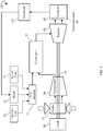
- FIG. 1 is a block diagram illustrating a combustion fuel system 100 (also referred herein as a liquid fuel system or a fuel system), in accordance with an example embodiment of the disclosure.
- the system 100 may use liquid or gaseous fuel, such as natural gas and/or a synthetic gas.
- one or more fuel nozzles 12 intake a liquid fuel supply 14 and a gaseous fuel supply 35.
- one or more fuel nozzles 12 may be used to intake liquid fuel and one or more other fuel nozzles 12 may be used to intake gaseous fuel.
- Some of the fuel nozzles are pilot nozzles and other fuel nozzles are main nozzles.
- the fuel nozzles 12 may intake a water supply 15.
- the system 100 mixes the liquid fuel with the water supply 15 upstream from and/or within the fuel nozzles 12. Mixing the liquid fuel with the water supply 15 may improve the efficiency of byproduct, e.g., NOx, suppression, thereby reducing production and exhaust of the byproducts from the system 100.
- the fuel nozzles 12 may be disposed inside the combustor 16.
- the combustor 16 directs the exhaust gases through a turbine 18 toward an exhaust system 20.
- Exhaust system 20 may include a plurality of thermocouples 50. Although only one combustor 16 is shown in FIG.
- a plurality of combustors 16 may be arranged circumferentially about the turbine 18. Each of the plurality of combustors 16 may include separate fuel nozzles 12. As the exhaust gases pass through the turbine 18, the gases force turbine blades to rotate a shaft 22 along an axis of the system 100. As illustrated, the shaft 22 is connected to various components of the system 100, including a compressor 24. The compressor 24 also includes blades coupled to the shaft 22. As the shaft 22 rotates, the blades within the compressor 24 also rotate, thereby compressing air from an air intake 26 through the compressor 24 and into the fuel nozzles 12 and/or combustor 16.
- the shaft 22 may also be connected to a load 28, which may be a vehicle or a stationary load, such as an electrical generator in a power plant.
- the load 28 may include any suitable device capable of being powered by the rotational output of system 100.
- the system 100 may further include a controller 400 that may be operatively connected to water supply 15.
- the controller 400 may also operatively receive exhaust spread data from thermocouples 50 in exhaust system 20.
- performance of the combustion fuel system 100 and turbine 18 may degrade due to changes of parameters of fuel nozzles and mixing valves.
- the flow path in the fuel nozzles and the mixing valves can be changed due to corrosion, erosion, and fouling.
- Solid materials can build up on inner surfaces of the fuel nozzles and mixing valves.
- the solid materials can be produced when liquid fuel (for example, diesel) is exposed to high temperature, so small portions of liquid fuel may become solid due to coking.
- liquid fuel for example, diesel
- Some solid materials remain inside fuel nozzles and mixing valves and therefore decrease the cross-section area of the fuel nozzles and mixing valves. Decreasing the cross-section areas of the fuel nozzles and mixing valves may result in a decreased fuel flow rate and, therefore, in decreased expected performance of the combustion fuel system thus the gas turbine.
- a water injection to the fuel nozzles can be used to clean up the built up solid materials from fuel nozzles and mixing valves.
- the water injection can be enabled each time after the turbine engine stops burning the liquid fuel and prior to starting to run on gaseous fuel.
- the water injection can be enabled to liquid fuel nozzles during gaseous fuel operations.
- an exhaust spread data can be recorded using, for example, thermocouples 50. The exhaust spread data recorded at different times of water injection can be further analyzed to track changes of physical parameters of fuel nozzles and mixing valves and predict the physical parameters of fuel nozzles and mixing valves in future time.
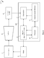
- FIG. 2 is a block diagram illustrating an example system 200 for predicting physical parameters of a combustion fuel system, according to an example embodiment of the disclosure.
- the system 200 includes an exhaust spread module 30, a diagnostics module 42, an injection controller 44, a prediction module 48, and an adaptive system module 46.
- Some of the modules of the system 200 can be implemented as instructions stored in a memory and executed by a processor of controller 400.
- the exhaust spread module 30 is operable to read temperature data from thermocouples 50 during operations of turbine 18.
- the exhaust spread module 30 may measure an exhaust spread data captured when water is injected in fuel nozzles 12.
- Thermocouples 50 can be arranged circumferentially on exhaust system 20 and can be correlated to particular locations of mixing valves and fuel nozzles.
- combustion fuel system 100 bums gaseous fuel
- the exhaust spread is generally of a uniform pattern.
- the injection of water during gas fuel operation forces the data in the exhaust spread to be more distinctive at different locations.
- the changes of exhaust spread at the particular position can be correlated to a particular mixing valve or a particular fuel nozzle. For example, if the temperature at the particular location in exhaust spread becomes higher over time with each next water injection, it may indicate that the cross-section area of a mixing valve located at the particular location decreases since a lesser amount of water is passing through the cross-section area of the mixing valve. Similarly, the change of the temperature at the particular location in exhaust spread can be correlated to a change of fuel flow rate for a particular fuel nozzle.
- initial exhaust spread can be recorded shortly after the combustion fuel system is commissioned.
- initial physical parameters such as flow numbers (sizes of the fuel nozzles) and flow rates are known from manufacturer. Therefore, initial exhaust spread may represent a signature of initial physical parameters of the fuel nozzles and the mixing valves.
- an exhaust temperature spread is recorded each time when enabling water injection in fuel nozzles. Changes in exhaust spreads recorded during water injections may indicate changes of physical parameters of the fuel nozzles and mixing valves from the initial physical parameters.
- diagnostics module 42 may store and analyze historical records containing exhaust spreads captured in response to water injections and times when the exhaust spread are captured.
- the diagnostic module 42 can also keep time records for fuel flow rates during both gaseous fuel operations and liquid fuel operations, and other physical parameters of the combustion fuel system. Based on the historical records, the diagnostics module 42 may report current state of physical parameters of fuel nozzles and mixing valves and issue recommendations regarding maintenance of the combustion fuel system.
- prediction module 48 may predict, based on the historical records, the productivity of a combustion fuel system at future times. For example, prediction module 48 may predict flow rates for a particular fuel nozzle and cross-section area of a particular mixing valve in a pre-determined time period. The prediction module 48 may issue warnings regarding the remaining lifetime for a particular fuel nozzle and a particular mixing valve.
- the prediction and diagnostics of physical parameters of a combustion fuel system may be based on adaptive system module 46.
- the adaptive system module 46 may include an analytical model.
- the analytical model may correlate the exhaust temperature spreads to physical parameters of a combustion fuel system, for example, to flow rates of fuel nozzles and cross-section areas of mixing valves.
- the analytical model can be further operable to provide guidelines or permissive for gas turbines operations, such as variation of fuel flow rate, or firing temperature, or an adjusted water purge duration of the combustion fuel system.
- the analytical model can predict the physical parameters of the combustion fuel system at a future time.
- the analytical model may include a machine learning algorithm, an expert system, a neural network, an extrapolation model, and so forth.
- FIG. 3 is flow chart illustrating an example method 300 for predicting physical parameters of a combustion fuel system, according to an embodiment of the disclosure.
- the operations of the method 300 may be performed by system 200 for predicting physical parameters of a combustion fuel system.
- the operations of method 300 may be embedded in program instructions of controller 400.
- the method 300 may analyze exhaust temperature spread data captured during injection of water into combustor 16 to track changes in physical parameters of combustion fuel system over time.
- method 300 can commence with causing water injection in at least one combustor.
- the water injection is associated with at least one time.
- a first water injection is carried out at time of commissioning the fuel system.
- method 300 includes measuring exhaust spread data associated with the water injection.
- the exhaust spread data are correlated to at least one physical parameter associated with a nozzle or a valve of the fuel system.
- the nozzle can include a main liquid fuel nozzle and a pilot liquid fuel nozzle.
- Physical parameters may include a fuel rate of the nozzle and a cross-section area of the valve.
- the exhaust spread data, at least one physical parameter, and the at least one time are stored to a database.
- historical data from the database are provided to an analytical model.
- the analytical model is operable to predict, based at least partially on the stored historical data, at least one future physical parameter associated with a future time.
- the historical data may include exhaust temperature spreads captured during gaseous fuel operations.
- the historical data may further include exhaust temperature spreads captured during clean-up water injection after finishing liquid fuel operations.
- method 300 includes predicting, based on the analytical model and the historical data, changes in productivity of the fuel system.
- method 300 can allow issuing, based on the prediction, a maintenance recommendation for the fuel system.
- operational adjustment of the fuel system can performed based partially on the prediction.
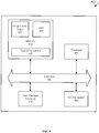
- FIG. 4 depicts a block diagram illustrating an example controller 400, in accordance with an embodiment of the disclosure. More specifically, the elements of the controller 400 may be used to run a combustion fuel system under a plurality of operational conditions while within predetermined combustion operational boundaries, automatically collect operational data associated with the combustion fuel system while the combustion fuel system is running, store the operational data, generate a set of constants for one or more predetermined combustion transfer functions based on the operational data, and store the set of constants in the combustion control system to be used during the commissioning of the combustion fuel system.
- the controller 400 may include a memory 410 that stores programmed logic 420 (e.g., software) and may store data 430, such as operational data associated with the combustion fuel system, the set of constants, and the like.
- the memory 410 also may include an operating system 440.
- a processor 450 may utilize the operating system 440 to execute the programmed logic 420, and in doing so, may also utilize the data 430.
- a data bus 460 may provide communication between the memory 410 and the processor 450.
- Users may interface with the controller 400 via at least one user interface device 470, such as a keyboard, mouse, control panel, or any other device capable of communicating data to and from the controller 400.
- the controller 400 may be in communication with the combustion fuel system while operating, as well as in communication with the combustion fuel system combustion control system offline while not operating, via an input/output (I/O) interface 480. Additionally, it should be appreciated that other external devices or multiple other combustion fuel systems or combustors may be in communication with the controller 400 via the I/O interface 480.
- the controller 400 may be located remotely with respect to the turbine system; however, it may be co-located or even integrated with the turbine system. Further, the controller 400 and the programmed logic 420 implemented thereby may include software, hardware, firmware, or any combination thereof. It should also be appreciated that multiple controllers 400 may be used, whereby different features described herein may be executed on one or more different controllers 400.
- references are made to block diagrams of systems, methods, apparatuses, and computer program products, according to example embodiments of the disclosure. It will be understood that at least some of the blocks of the block diagrams, and combinations of blocks in the block diagrams, may be implemented at least partially by computer program instructions. These computer program instructions may be loaded onto a general purpose computer, special purpose computer, special purpose hardware-based computer, or other programmable data processing apparatus to produce a machine, such that the instructions which execute on the computer or other programmable data processing apparatus create means for implementing the functionality of at least some of the blocks of the block diagrams, or combinations of blocks in the block diagrams discussed.
- These computer program instructions may also be stored in a computer-readable memory that can direct a computer or other programmable data processing apparatus to function in a particular manner, such that the instructions stored in the computer-readable memory produce an article of manufacture including instruction means that implement the function specified in the block or blocks.
- the computer program instructions may also be loaded onto a computer or other programmable data processing apparatus to cause a series of operational steps to be performed on the computer or other programmable apparatus to produce a computer implemented process such that the instructions that execute on the computer or other programmable apparatus provide steps for implementing the functions specified in the block or blocks.
- One or more components of the systems and one or more elements of the methods described herein may be implemented through an application program running on an operating system of a computer. They also may be practiced with other computer system configurations, including hand-held devices, multiprocessor systems, microprocessor based or programmable consumer electronics, mini-computers, mainframe computers, and the like.
- Application programs that are components of the systems and methods described herein may include routines, programs, components, data structures, and so forth that implement certain abstract data types and perform certain tasks or actions.
- the application program in whole or in part
- the application program may be located in local memory or in other storage.
- the application program in whole or in part
Landscapes
- Engineering & Computer Science (AREA)
- Chemical & Material Sciences (AREA)
- Combustion & Propulsion (AREA)
- Mechanical Engineering (AREA)
- General Engineering & Computer Science (AREA)
- Regulation And Control Of Combustion (AREA)
- Testing And Monitoring For Control Systems (AREA)
- Feeding And Controlling Fuel (AREA)
Abstract
Description
- The disclosure relates to the art of turbomachines, and, more particularly, to systems and methods of predicting physical parameters for a combustion fuel system.
- Combustion fuel systems burn gaseous fuel (for example, natural gas). Some combustion fuel systems can burn gaseous fuel and liquid fuel, such as diesel. Typically, a dual fuel combustion system operates using the gaseous fuel, while the liquid fuel is used as a backup fuel when the gaseous fuel is not available due to, for example, issues with delivery of the gaseous fuel to the combustion fuel system.
- A combustion chamber of the combustion fuel system can be configured to receive both the gaseous fuel and the liquid fuel. Use of liquid fuel may result in by-products or loss of material due to erosion/corrosion, which may degrade flow paths for delivering fuels in the combustor chamber and, as a result, decrease productivity and reliability of the combustion fuel system.
- This disclosure relates to systems and methods of predicting physical parameters for a combustion fuel system. Certain embodiments of the disclosure can facilitate detecting failures related to fuel nozzles and mixing valves of the combustion fuel system. According to one embodiment of the disclosure, a method of predicting physical parameters for a fuel system includes causing water injection in at least one combustor. The water injection can be associated with at least one time. The method can include measuring exhaust temperature spread data associated with the water injection and correlating the exhaust spread data to at least one physical parameter associated with a nozzle or a valve of the fuel system. The method can further include storing the exhaust spread data, at least one physical parameter, and at least one time to a database. Historical data can be provided from the database to an analytical model. The analytical model can be operable to predict, based at least partially on the stored historical data, at least one future physical parameter associated with a future time. The method can predict changes in a productivity of the fuel system. Additionally, the method can issue, based at least partially on the prediction, a maintenance recommendation for the fuel system. Operational adjustments of the fuel system can be performed based at least partially on the prediction.
- In some embodiments of the disclosure, at least one water injection is performed at a commissioning of the fuel system. In certain embodiments of the disclosure, the water injection can be performed via at least one pilot valve of at least one pilot nozzle of the fuel system. In some embodiments of the disclosure, the water injection is performed via at least one main valve or at least one main nozzle of the fuel system.
- In some embodiments of the disclosure, physical parameters include a flow rate of at least one nozzle of the fuel system and a cross-section area of at least one valve of the fuel system.
- In some embodiments of the disclosure, the water injection is performed while operating on a gas fuel. In certain embodiments, the water injection is performed after a liquid fuel operation.
- In some embodiments of the disclosure, the analytical model is operable to provide guidelines or permissive for gas turbines operations, a variation of a fuel flow rate, a firing temperature, or an adjusted water purge duration of the fuel system.
- In certain embodiments of the disclosure, the exhaust spread data is measured with a set of thermocouples disposed adjacent to an exhaust system associated with the combustor.
- According to another embodiment of the disclosure, a system for predicting physical parameters of a combustion fuel system is provided. The system can include a combustor. The system can further include a processor communicatively coupled to a memory, with the memory storing instructions which, when executed by the processing circuit, perform certain operations. These operations can include causing at least one water injection in at least one combustor, the at least one water injection being associated with at least one time; measuring at least one exhaust spread data associated with the at least one water injection; correlating the at least one exhaust spread data with at least one physical parameter associated with at least one of a nozzle or a valve of the liquid fuel system; storing the at least one exhaust spread data, the at least one physical parameter, and the at least one time to a database; and providing stored data from the database to an analytical model, wherein the analytical model is operable to predict, based at least partially on the stored data, at least one future physical parameter associated with a future time.
- Other embodiments, systems, methods, features, and aspects will become apparent from the following description taken in conjunction with the following drawings.
-
-
FIG. 1 is a block diagram illustrating an example combustion fuel system, according to some embodiments of the disclosure. -
FIG. 2 is a block diagram illustrating an example system for predicting physical parameters of a combustion fuel system, according to an embodiment of the disclosure. -
FIG. 3 is flow chart illustrating an example method of predicting physical parameters of a combustion fuel system, according to an embodiment of the disclosure. -
FIG. 4 is a block diagram illustrating an example controller for controlling a combustion fuel system, in accordance with an embodiment of the disclosure. - The following detailed description includes references to the accompanying drawings, which form part of the detailed description. The drawings depict illustrations, in accordance with example embodiments. These example embodiments, which are also referred to herein as "examples," are described in enough detail to enable those skilled in the art to practice the present subject matter. The example embodiments may be combined, other embodiments may be utilized, or structural, logical, and electrical changes may be made, without departing from the scope of the claimed subject matter. The following detailed description is, therefore, not to be taken in a limiting sense, and the scope is defined by the appended claims and their equivalents.
- Certain embodiments of the disclosure can include systems and methods of predicting physical parameters of a combustion fuel system. The disclosed systems and methods may provide diagnostics of fuel nozzles and mixing valves of the combustion fuel system, and facilitate issuing a maintenance recommendation for the combustion fuel system.
- In some example embodiments of the disclosure, a processor may cause water injection in at least one combustor. The water injection can be associated with at least one time. The processor may measure exhaust spread data associated with the water injection and correlate the exhaust spread data to at least one physical parameter associated with a nozzle or a valve of a combustion fuel system. The processor may also store the exhaust spread data, at least one physical parameter, and at least one time to a database. The processor may provide stored historical data from the database to an analytical model. The analytical model can be operable to predict, based at least partially on the stored historical data, at least one future physical parameter associated with a future time.
- Technical effects of certain embodiments of the disclosure may include performing a diagnostic of a combustion fuel system without disassembling the combustion fuel system. Further technical effects of certain embodiments of the disclosure may allow increasing the probability of detecting hardware failures related to performance of fuel nozzles and mixing valves of the combustion fuel system. Yet further technical effects of certain embodiments of the disclosure provide information concerning health of the combustion fuel system and allow a reduction in combustion related trips, forced outage time, and unplanned costs.
- The following provides a detailed description of various example embodiments related to systems and methods of predicting physical parameters for a combustion fuel system.
- Turning now to the drawings,
FIG. 1 is a block diagram illustrating a combustion fuel system 100 (also referred herein as a liquid fuel system or a fuel system), in accordance with an example embodiment of the disclosure. Thesystem 100 may use liquid or gaseous fuel, such as natural gas and/or a synthetic gas. As depicted, one ormore fuel nozzles 12 intake aliquid fuel supply 14 and agaseous fuel supply 35. For example, one ormore fuel nozzles 12 may be used to intake liquid fuel and one or moreother fuel nozzles 12 may be used to intake gaseous fuel. Some of the fuel nozzles are pilot nozzles and other fuel nozzles are main nozzles. In addition, thefuel nozzles 12 may intake awater supply 15. Thesystem 100 mixes the liquid fuel with thewater supply 15 upstream from and/or within thefuel nozzles 12. Mixing the liquid fuel with thewater supply 15 may improve the efficiency of byproduct, e.g., NOx, suppression, thereby reducing production and exhaust of the byproducts from thesystem 100. Although shown schematically as being outside or separate from thecombustor 16, thefuel nozzles 12 may be disposed inside thecombustor 16. The fuel and water (when used), mixture combusts in a chamber within thecombustor 16, thereby creating hot pressurized exhaust gases. Thecombustor 16 directs the exhaust gases through aturbine 18 toward anexhaust system 20.Exhaust system 20 may include a plurality ofthermocouples 50. Although only onecombustor 16 is shown inFIG. 1 , in certain embodiments, a plurality ofcombustors 16 may be arranged circumferentially about theturbine 18. Each of the plurality ofcombustors 16 may includeseparate fuel nozzles 12. As the exhaust gases pass through theturbine 18, the gases force turbine blades to rotate ashaft 22 along an axis of thesystem 100. As illustrated, theshaft 22 is connected to various components of thesystem 100, including acompressor 24. Thecompressor 24 also includes blades coupled to theshaft 22. As theshaft 22 rotates, the blades within thecompressor 24 also rotate, thereby compressing air from anair intake 26 through thecompressor 24 and into thefuel nozzles 12 and/orcombustor 16. Theshaft 22 may also be connected to aload 28, which may be a vehicle or a stationary load, such as an electrical generator in a power plant. Theload 28 may include any suitable device capable of being powered by the rotational output ofsystem 100. Thesystem 100 may further include acontroller 400 that may be operatively connected towater supply 15. Thecontroller 400 may also operatively receive exhaust spread data fromthermocouples 50 inexhaust system 20. - During operations, performance of the
combustion fuel system 100 andturbine 18 may degrade due to changes of parameters of fuel nozzles and mixing valves. The flow path in the fuel nozzles and the mixing valves can be changed due to corrosion, erosion, and fouling. - Solid materials can build up on inner surfaces of the fuel nozzles and mixing valves. The solid materials can be produced when liquid fuel (for example, diesel) is exposed to high temperature, so small portions of liquid fuel may become solid due to coking. Some solid materials remain inside fuel nozzles and mixing valves and therefore decrease the cross-section area of the fuel nozzles and mixing valves. Decreasing the cross-section areas of the fuel nozzles and mixing valves may result in a decreased fuel flow rate and, therefore, in decreased expected performance of the combustion fuel system thus the gas turbine.
- Some residual of oil may build up when
system 100 operates on liquid fuel. A water injection to the fuel nozzles can be used to clean up the built up solid materials from fuel nozzles and mixing valves. The water injection can be enabled each time after the turbine engine stops burning the liquid fuel and prior to starting to run on gaseous fuel. In some embodiments of the disclosure, the water injection can be enabled to liquid fuel nozzles during gaseous fuel operations. In certain embodiments of the disclosure, during injection of the water, an exhaust spread data can be recorded using, for example, thermocouples 50. The exhaust spread data recorded at different times of water injection can be further analyzed to track changes of physical parameters of fuel nozzles and mixing valves and predict the physical parameters of fuel nozzles and mixing valves in future time. -
FIG. 2 is a block diagram illustrating anexample system 200 for predicting physical parameters of a combustion fuel system, according to an example embodiment of the disclosure. Thesystem 200 includes anexhaust spread module 30, adiagnostics module 42, aninjection controller 44, aprediction module 48, and anadaptive system module 46. Some of the modules of thesystem 200 can be implemented as instructions stored in a memory and executed by a processor ofcontroller 400. - In some embodiments of the disclosure, the
exhaust spread module 30 is operable to read temperature data fromthermocouples 50 during operations ofturbine 18. For example, theexhaust spread module 30 may measure an exhaust spread data captured when water is injected infuel nozzles 12.Thermocouples 50 can be arranged circumferentially onexhaust system 20 and can be correlated to particular locations of mixing valves and fuel nozzles. Whencombustion fuel system 100 bums gaseous fuel, the exhaust spread is generally of a uniform pattern. The injection of water during gas fuel operation forces the data in the exhaust spread to be more distinctive at different locations. By analyzing the exhaust spreads recorded during the water injections at different times, changes of temperature at a particular position in the exhaust spread can be tracked. The changes of exhaust spread at the particular position can be correlated to a particular mixing valve or a particular fuel nozzle. For example, if the temperature at the particular location in exhaust spread becomes higher over time with each next water injection, it may indicate that the cross-section area of a mixing valve located at the particular location decreases since a lesser amount of water is passing through the cross-section area of the mixing valve. Similarly, the change of the temperature at the particular location in exhaust spread can be correlated to a change of fuel flow rate for a particular fuel nozzle. - An initial exhaust spread can be recorded shortly after the combustion fuel system is commissioned. When the combustion fuel system is commissioned, initial physical parameters, such as flow numbers (sizes of the fuel nozzles) and flow rates are known from manufacturer. Therefore, initial exhaust spread may represent a signature of initial physical parameters of the fuel nozzles and the mixing valves. During following operations of the combustion fuel system, an exhaust temperature spread is recorded each time when enabling water injection in fuel nozzles. Changes in exhaust spreads recorded during water injections may indicate changes of physical parameters of the fuel nozzles and mixing valves from the initial physical parameters.
- In some embodiments of the disclosure,
diagnostics module 42 may store and analyze historical records containing exhaust spreads captured in response to water injections and times when the exhaust spread are captured. Thediagnostic module 42 can also keep time records for fuel flow rates during both gaseous fuel operations and liquid fuel operations, and other physical parameters of the combustion fuel system. Based on the historical records, thediagnostics module 42 may report current state of physical parameters of fuel nozzles and mixing valves and issue recommendations regarding maintenance of the combustion fuel system. - In some embodiments of the disclosure,
prediction module 48 may predict, based on the historical records, the productivity of a combustion fuel system at future times. For example,prediction module 48 may predict flow rates for a particular fuel nozzle and cross-section area of a particular mixing valve in a pre-determined time period. Theprediction module 48 may issue warnings regarding the remaining lifetime for a particular fuel nozzle and a particular mixing valve. - In some embodiments of the disclosure, the prediction and diagnostics of physical parameters of a combustion fuel system may be based on
adaptive system module 46. Theadaptive system module 46 may include an analytical model. The analytical model may correlate the exhaust temperature spreads to physical parameters of a combustion fuel system, for example, to flow rates of fuel nozzles and cross-section areas of mixing valves. The analytical model can be further operable to provide guidelines or permissive for gas turbines operations, such as variation of fuel flow rate, or firing temperature, or an adjusted water purge duration of the combustion fuel system. - In some embodiments of the disclosure, the analytical model can predict the physical parameters of the combustion fuel system at a future time. In various embodiments, the analytical model may include a machine learning algorithm, an expert system, a neural network, an extrapolation model, and so forth.
-
FIG. 3 is flow chart illustrating anexample method 300 for predicting physical parameters of a combustion fuel system, according to an embodiment of the disclosure. The operations of themethod 300 may be performed bysystem 200 for predicting physical parameters of a combustion fuel system. The operations ofmethod 300 may be embedded in program instructions ofcontroller 400. Themethod 300 may analyze exhaust temperature spread data captured during injection of water intocombustor 16 to track changes in physical parameters of combustion fuel system over time. - In
block 302,method 300 can commence with causing water injection in at least one combustor. The water injection is associated with at least one time. A first water injection is carried out at time of commissioning the fuel system. - In
block 304,method 300 includes measuring exhaust spread data associated with the water injection. - In
block 306, the exhaust spread data are correlated to at least one physical parameter associated with a nozzle or a valve of the fuel system. The nozzle can include a main liquid fuel nozzle and a pilot liquid fuel nozzle. Physical parameters may include a fuel rate of the nozzle and a cross-section area of the valve. - In
block 308, the exhaust spread data, at least one physical parameter, and the at least one time are stored to a database. - In
block 310, historical data from the database are provided to an analytical model. The analytical model is operable to predict, based at least partially on the stored historical data, at least one future physical parameter associated with a future time. The historical data may include exhaust temperature spreads captured during gaseous fuel operations. The historical data may further include exhaust temperature spreads captured during clean-up water injection after finishing liquid fuel operations. - In
block 312,method 300 includes predicting, based on the analytical model and the historical data, changes in productivity of the fuel system. - In
block 314,method 300 can allow issuing, based on the prediction, a maintenance recommendation for the fuel system. - In
block 316, operational adjustment of the fuel system can performed based partially on the prediction. -
FIG. 4 depicts a block diagram illustrating anexample controller 400, in accordance with an embodiment of the disclosure. More specifically, the elements of thecontroller 400 may be used to run a combustion fuel system under a plurality of operational conditions while within predetermined combustion operational boundaries, automatically collect operational data associated with the combustion fuel system while the combustion fuel system is running, store the operational data, generate a set of constants for one or more predetermined combustion transfer functions based on the operational data, and store the set of constants in the combustion control system to be used during the commissioning of the combustion fuel system. Thecontroller 400 may include amemory 410 that stores programmed logic 420 (e.g., software) and may storedata 430, such as operational data associated with the combustion fuel system, the set of constants, and the like. Thememory 410 also may include anoperating system 440. - A
processor 450 may utilize theoperating system 440 to execute the programmedlogic 420, and in doing so, may also utilize thedata 430. A data bus 460 may provide communication between thememory 410 and theprocessor 450. Users may interface with thecontroller 400 via at least one user interface device 470, such as a keyboard, mouse, control panel, or any other device capable of communicating data to and from thecontroller 400. Thecontroller 400 may be in communication with the combustion fuel system while operating, as well as in communication with the combustion fuel system combustion control system offline while not operating, via an input/output (I/O)interface 480. Additionally, it should be appreciated that other external devices or multiple other combustion fuel systems or combustors may be in communication with thecontroller 400 via the I/O interface 480. In the illustrated embodiment of the disclosure, thecontroller 400 may be located remotely with respect to the turbine system; however, it may be co-located or even integrated with the turbine system. Further, thecontroller 400 and the programmedlogic 420 implemented thereby may include software, hardware, firmware, or any combination thereof. It should also be appreciated thatmultiple controllers 400 may be used, whereby different features described herein may be executed on one or moredifferent controllers 400. - References are made to block diagrams of systems, methods, apparatuses, and computer program products, according to example embodiments of the disclosure. It will be understood that at least some of the blocks of the block diagrams, and combinations of blocks in the block diagrams, may be implemented at least partially by computer program instructions. These computer program instructions may be loaded onto a general purpose computer, special purpose computer, special purpose hardware-based computer, or other programmable data processing apparatus to produce a machine, such that the instructions which execute on the computer or other programmable data processing apparatus create means for implementing the functionality of at least some of the blocks of the block diagrams, or combinations of blocks in the block diagrams discussed.
- These computer program instructions may also be stored in a computer-readable memory that can direct a computer or other programmable data processing apparatus to function in a particular manner, such that the instructions stored in the computer-readable memory produce an article of manufacture including instruction means that implement the function specified in the block or blocks. The computer program instructions may also be loaded onto a computer or other programmable data processing apparatus to cause a series of operational steps to be performed on the computer or other programmable apparatus to produce a computer implemented process such that the instructions that execute on the computer or other programmable apparatus provide steps for implementing the functions specified in the block or blocks.
- One or more components of the systems and one or more elements of the methods described herein may be implemented through an application program running on an operating system of a computer. They also may be practiced with other computer system configurations, including hand-held devices, multiprocessor systems, microprocessor based or programmable consumer electronics, mini-computers, mainframe computers, and the like.
- Application programs that are components of the systems and methods described herein may include routines, programs, components, data structures, and so forth that implement certain abstract data types and perform certain tasks or actions. In a distributed computing environment, the application program (in whole or in part) may be located in local memory or in other storage. In addition, or alternatively, the application program (in whole or in part) may be located in remote memory or in storage to allow for circumstances where tasks are performed by remote processing devices linked through a communications network.
- Many modifications and other embodiments of the example descriptions set forth herein to which these descriptions pertain will come to mind having the benefit of the teachings presented in the foregoing descriptions and the associated drawings. Thus, it will be appreciated that the disclosure may be embodied in many forms and should not be limited to the example embodiments described above.
- Therefore, it is to be understood that the disclosure is not to be limited to the specific embodiments disclosed and that modifications and other embodiments are intended to be included within the scope of the appended claims. Although specific terms are employed herein, they are used in a generic and descriptive sense only and not for purposes of limitation.
- Various aspects and embodiments of the present invention are defined by the following numbered clauses:
- 1. A method of predicting performance of a fuel system, the method comprising:
- causing water injection in at least one combustor, the water injection being associated with at least one time;
- measuring exhaust spread data associated with the water injection;
- correlating the exhaust spread data to at least one physical parameter associated with a nozzle or a valve of the fuel system;
- storing the exhaust spread data, the at least one physical parameter, and the at least one time to a database; and
- providing stored historical data from the database to an analytical model, wherein the analytical model is operable to predict, based at least partially on the stored historical data, at least one future physical parameter associated with a future time.
- 2. The method of clause 1, wherein the at least one time is associated with commissioning of the fuel system.
- 3. The method of any preceding clause, when the water injection is performed via at least one pilot valve of at least one pilot nozzle of the fuel system.
- 4. The method of any preceding clause, wherein the water injection is performed via at least one main valve or at least one main nozzle of the fuel system.
- 5. The method of any preceding clause, wherein the at least one physical parameter includes at least a flow rate of at least one nozzle of the fuel system and a cross-section area of at least one valve of the fuel system.
- 6. The method of any preceding clause, wherein the water injection is performed during a gas fuel operation.
- 7. The method of any preceding clause, wherein the water injection is performed after a liquid fuel operation.
- 8. The method of any preceding clause, wherein the analytical model is further operable to provide guidelines or permissive for gas turbines operations, a variation in fuel flow rate, a firing temperature, or an adjusted water purge duration of the combustion fuel system.
- 9. The method of any preceding clause, further comprising performing, based at least partially on the analytical model, at least one of the following:
- predicting changes in a productivity of the fuel system;
- issuing, based at least partially on the prediction, at least one maintenance recommendation for the fuel system; or
- performing, based at least partially on the prediction, an operational adjustment of the fuel system.
- 10. The method of any preceding clause, wherein the exhaust spread data is measured with a set of thermocouples disposed adjacent to an exhaust system associated with the at least one combustor.
- 11. A system for predicting performance of a liquid fuel system, the system comprising:
- a processor;
- a memory communicatively coupled to the processor, the memory storing instructions which when executed by the processor perform operations comprising:
- causing at least one water injection in at least one combustor, the at least one water injection being associated with at least one time;
- measuring at least one exhaust spread data associated with the at least one water injection;
- correlating the at least one exhaust spread data with at least one physical parameter associated with at least one of a nozzle or a valve of the liquid fuel system;
- storing the at least one exhaust spread data, the at least one physical parameter, and the at least one time to a database; and
- providing stored data from the database to an analytical model, wherein the analytical model is operable to predict, based at least partially on the stored data, at least one future physical parameter associated with a future time.
- 12. The system of any preceding clause, wherein the at least one time is associated with commissioning of the liquid fuel system.
- 13. The method of any preceding clause, wherein the at least one water injection is performed via at least one pilot valve or at least one pilot nozzle of the liquid fuel system.
- 14. The system of any preceding clause, wherein the at least one water injection is performed via at least one main valve or at least one main nozzle of the liquid fuel system.
- 15. The system of any preceding clause, wherein the at least one physical parameter includes at least a flow rate of at least one nozzle of the liquid fuel system and a cross-section area of at least one valve of the liquid fuel system.
- 16. The system of any preceding clause, wherein the at least one water injection is performed during a gas fuel operation.
- 17. The system of any preceding clause, wherein the at least one water injection is performed after a liquid fuel operation.
- 18. The system of any preceding clause, wherein the analytical model is further operable to provide guidelines or permissive for gas turbines operations, a variation of a fuel flow rate, a firing temperature, or an adjusted water purge duration of the combustion fuel system.
- 19. The system of any preceding clause, further comprising performing, based on the analytical model, at least one of the following:
- predicting changes in a productivity of the liquid fuel system;
- issuing, based at least partially, on the prediction, at least one maintenance recommendation for the liquid fuel system; or
- performing, based at least partially on the prediction, operational adjustment of the liquid fuel system.
- 20. A system comprising:
- a combustor;
- a processor;
- a memory communicatively coupled to the processor, the memory storing instructions which when executed by the processor perform operations comprising:
- causing at least one water injection in the combustor, the at least one water injection being associated with at least one time;
- measuring at least one exhaust spread data associated with the at least one water injection;
- correlating the at least one exhaust spread data to at least one physical parameter associated with at least one of a nozzle and a valve of a liquid fuel system;
- storing the at least one exhaust spread data, the at least one physical parameter, and the at least one time to a database;
- providing stored data from the database to an analytical model, wherein the analytical model is operable to predict, based at least partially on the historical data, at least one future physical parameter associated with a future time;
- predicting, based at least partially on the analytical model and the stored data, changes in a productivity of the liquid fuel system;
- issuing, based at least partially on the prediction, at least one maintenance recommendation for the liquid fuel system; and
- performing, based at least partially on the prediction, operational adjustment of the liquid fuel system.
Claims (10)
- A method (300) for predicting performance of a fuel system (100), the method comprising:causing water injection in at least one combustor (16), the water injection being associated with at least one time;measuring exhaust spread data associated with the water injection;correlating the exhaust spread data to at least one physical parameter associated with a nozzle (12) or a valve of the fuel system (100);storing the exhaust spread data, the at least one physical parameter, and the at least one time to a database; andproviding stored historical data from the database to a model, wherein the model is operable to:provide a variation correlation of the at least one physical parameter to at least one of the following: a temperature, a velocity, or a purge duration of the fuel system (100); andpredict, based at least partially on the stored historical data, at least one future physical parameter associated with a future time;predicting, based at least partially on the model and the stored historical data, changes in a productivity of the fuel system;issuing, based at least partially on the prediction, at least one maintenance recommendation for the fuel system; andperforming, based at least partially on the prediction, an operational adjustment of the fuel system (100).
- The method (300) of claim 1, wherein the at least one time is associated with commissioning of the fuel system (100).
- The method (300) of claim 1 or 2, when the water injection is performed via at least one pilot valve of at least one pilot nozzle of the fuel system (100) or via at least one main valve or at least one main nozzle of the fuel system (100).
- The method (300) of claim 1, 2 or 3, wherein the at least one physical parameter includes at least a flow rate of at least one nozzle (12) of the fuel system and a cross-section area of at least one valve of the fuel system.
- The method (300) of any of claims 1 to 4, wherein the water injection is performed during a gas fuel operation or after a liquid fuel operation.
- A system (400) for predicting performance of a liquid fuel system (100), the system comprising:a processor (450);a memory (410) communicatively coupled to the processor (450), the memory (450) storing instructions which when executed by the processor perform operations comprising:causing at least one water injection in at least one combustor (16), the at least one water injection being associated with at least one time;measuring at least one exhaust spread data associated with the at least one water injection;correlating the at least one exhaust spread data with the at least one physical parameter associated with at least one of a nozzle (12) or a valve of the liquid fuel system (100);storing the at least one exhaust spread data, the at least one physical parameter, and the at least one time to a database; andproviding stored data from the database to an analytical model, wherein the analytical model is operable to:provide a variation correlation of the at least one physical parameter to at least one of the following: a temperature, a velocity, or a purge duration of the liquid fuel system (100); andpredict, based at least partially on the stored data, at least one future physical parameter associated with a future time;predicting, based on the analytical model, changes in a productivity of the liquid fuel system (100);issuing, based at least partially, on the prediction, at least one maintenance recommendation for the liquid fuel system (100); andperforming, based at least partially on the prediction, operational adjustment of the liquid fuel system (100).
- The system (400) of claim 6, wherein:the at least one time is associated with commissioning of the liquid fuel system (100); andthe at least one water injection is performed during a gas fuel operation or after a liquid fuel operation.
- The system (400) of claim 6 or 7, wherein:the at least one water injection is performed via at least one pilot valve or at least one pilot nozzle (12) of the liquid fuel system; orthe at least one water injection is performed via at least one main valve or at least one main nozzle of the liquid fuel system.
- The system (400) of claim 6, 7 or 8, wherein the at least one physical parameter includes at least a flow rate of at least one nozzle (12) of the liquid fuel system (100) and a cross-section area of at least one valve of the liquid fuel system (100).
- A system comprising:a combustor (16);a processor (450);a memory (410) communicatively coupled to the processor (450), the memory (410) storing instructions which when executed by the processor perform operations comprising:causing at least one water injection in the combustor (16), the at least one water injection being associated with at least one time;measuring at least one exhaust spread data associated with the at least one water injection;correlating the at least one exhaust spread data to the at least one physical parameter associated with at least one of a nozzle (12) and a valve of a liquid fuel system (100);storing the at least one exhaust spread data, the at least one physical parameter, and the at least one time to a database;providing stored data from the database to an analytical model, wherein the analytical model is operable to predict, based at least partially on the historical data, at least one future physical parameter associated with a future time;predicting, based at least partially on the analytical model and the stored data, changes in a productivity of the liquid fuel system (100);issuing, based at least partially on the prediction, at least one maintenance recommendation for the liquid fuel system (100); andperforming, based at least partially on the prediction, operational adjustment of the liquid fuel system (100).
Applications Claiming Priority (1)
| Application Number | Priority Date | Filing Date | Title |
|---|---|---|---|
| US15/012,376 US20170218790A1 (en) | 2016-02-01 | 2016-02-01 | Systems and Methods of Predicting Physical Parameters for a Combustion Fuel System |
Publications (1)
| Publication Number | Publication Date |
|---|---|
| EP3239614A1 true EP3239614A1 (en) | 2017-11-01 |
Family
ID=57909519
Family Applications (1)
| Application Number | Title | Priority Date | Filing Date |
|---|---|---|---|
| EP17153469.6A Withdrawn EP3239614A1 (en) | 2016-02-01 | 2017-01-27 | Systems and methods of predicting physical parameters for a combustion fuel system |
Country Status (5)
| Country | Link |
|---|---|
| US (1) | US20170218790A1 (en) |
| EP (1) | EP3239614A1 (en) |
| JP (1) | JP6514725B2 (en) |
| KR (1) | KR102767568B1 (en) |
| CN (1) | CN107630755B (en) |
Families Citing this family (6)
| Publication number | Priority date | Publication date | Assignee | Title |
|---|---|---|---|---|
| CN109859449A (en) * | 2019-01-23 | 2019-06-07 | 新奥数能科技有限公司 | The analysis method and server of therrmodynamic system combustion state |
| EP3963191B8 (en) * | 2019-05-30 | 2025-06-18 | Siemens Energy Global GmbH & Co. KG | Gas turbine water injection for emissions reduction |
| JP7602978B2 (en) | 2021-07-13 | 2024-12-19 | 三菱重工業株式会社 | Gas turbine facility and method for suppressing ammonia emissions from gas turbine facility |
| EP4206468A1 (en) * | 2022-01-04 | 2023-07-05 | Pfeiffer Vacuum | Vacuum pump and vacuum system |
| CN120588922B (en) * | 2025-08-08 | 2025-11-07 | 浙江祥晋汽车零部件股份有限公司 | Electromagnetic valve maintenance method |
| CN120740336B (en) * | 2025-09-02 | 2025-11-07 | 湘潭沃瑞德能源科技有限公司 | Control method and system for fuel supply in volatilization kilns |
Citations (6)
| Publication number | Priority date | Publication date | Assignee | Title |
|---|---|---|---|---|
| US4259837A (en) * | 1979-06-13 | 1981-04-07 | General Electric Company | Water and steam injection system for emission control of gas turbines |
| US20090100293A1 (en) * | 2007-10-16 | 2009-04-16 | General Electric Company | Method and system for predicting turbomachinery failure events employing genetic algorithm |
| US20090271085A1 (en) * | 2008-04-25 | 2009-10-29 | Lauren Jeanne Buchalter | Method and system for operating gas turbine engine systems |
| US20140137564A1 (en) * | 2012-11-19 | 2014-05-22 | General Electric Company | Mitigation of Hot Corrosion in Steam Injected Gas Turbines |
| US20150160096A1 (en) * | 2013-12-05 | 2015-06-11 | General Electric Company | System and Method for Detecting an At-Fault Combustor |
| US20160026739A1 (en) * | 2014-07-23 | 2016-01-28 | Seema Chopra | Systems and Methods for Gas Turbine Operational Impact Modeling Using Statistical and Physics-Based Methodologies |
Family Cites Families (14)
| Publication number | Priority date | Publication date | Assignee | Title |
|---|---|---|---|---|
| JP2004204780A (en) * | 2002-12-25 | 2004-07-22 | Mitsubishi Heavy Ind Ltd | Device and method for monitoring irregularity of gas turbine |
| US8250017B2 (en) * | 2007-08-23 | 2012-08-21 | General Electric Company | System and method for prediction of gas turbine trips due to gas control valve failures |
| WO2012063102A1 (en) * | 2010-11-12 | 2012-05-18 | Dewitt Monte D | A steam generation system for thermal and related power applications using stoichiometric oxyhydrogen fuel stock |
| CA2870268C (en) * | 2011-04-11 | 2020-01-14 | Nostrum Energy Pte. Ltd. | Internally cooled high compression lean-burning internal combustion engine |
| WO2013111258A1 (en) * | 2012-01-23 | 2013-08-01 | トヨタ自動車株式会社 | Vehicle and vehicle control method |
| JP5946690B2 (en) * | 2012-05-02 | 2016-07-06 | 三菱日立パワーシステムズ株式会社 | Purge method and purge apparatus for gas turbine combustor |
| US20140075954A1 (en) * | 2012-09-14 | 2014-03-20 | General Electric Company | Methods And Systems For Substance Profile Measurements In Gas Turbine Exhaust |
| EP2711335A1 (en) * | 2012-09-24 | 2014-03-26 | Air Products And Chemicals, Inc. | Removal of dissolved gases for boiler feed water preparation |
| US20150020530A1 (en) * | 2013-07-18 | 2015-01-22 | General Electric Company | Gas turbine emissions control system and method |
| US10472992B2 (en) * | 2013-09-05 | 2019-11-12 | Enviro Power LLC | On-demand steam generator and control system |
| US20170219241A1 (en) * | 2014-01-09 | 2017-08-03 | Nautilus Data Technologies, Inc. | Data Center Infrastructure Management (DCIM) system comprising predictive analytics |
| US10012148B2 (en) * | 2014-05-23 | 2018-07-03 | General Electric Company | Method of purging a combustor |
| US10041668B2 (en) * | 2014-06-30 | 2018-08-07 | Tubitak | Hybrid homogenous-catalytic combustion system |
| KR101620814B1 (en) * | 2014-12-17 | 2016-05-12 | 주식회사 경동나비엔 | Hot water supply apparatus |
-
2016
- 2016-02-01 US US15/012,376 patent/US20170218790A1/en not_active Abandoned
-
2017
- 2017-01-25 CN CN201710055885.9A patent/CN107630755B/en active Active
- 2017-01-26 KR KR1020170012520A patent/KR102767568B1/en active Active
- 2017-01-26 JP JP2017011745A patent/JP6514725B2/en active Active
- 2017-01-27 EP EP17153469.6A patent/EP3239614A1/en not_active Withdrawn
Patent Citations (6)
| Publication number | Priority date | Publication date | Assignee | Title |
|---|---|---|---|---|
| US4259837A (en) * | 1979-06-13 | 1981-04-07 | General Electric Company | Water and steam injection system for emission control of gas turbines |
| US20090100293A1 (en) * | 2007-10-16 | 2009-04-16 | General Electric Company | Method and system for predicting turbomachinery failure events employing genetic algorithm |
| US20090271085A1 (en) * | 2008-04-25 | 2009-10-29 | Lauren Jeanne Buchalter | Method and system for operating gas turbine engine systems |
| US20140137564A1 (en) * | 2012-11-19 | 2014-05-22 | General Electric Company | Mitigation of Hot Corrosion in Steam Injected Gas Turbines |
| US20150160096A1 (en) * | 2013-12-05 | 2015-06-11 | General Electric Company | System and Method for Detecting an At-Fault Combustor |
| US20160026739A1 (en) * | 2014-07-23 | 2016-01-28 | Seema Chopra | Systems and Methods for Gas Turbine Operational Impact Modeling Using Statistical and Physics-Based Methodologies |
Also Published As
| Publication number | Publication date |
|---|---|
| JP6514725B2 (en) | 2019-05-15 |
| CN107630755A (en) | 2018-01-26 |
| KR20170091520A (en) | 2017-08-09 |
| JP2017187018A (en) | 2017-10-12 |
| US20170218790A1 (en) | 2017-08-03 |
| CN107630755B (en) | 2021-10-08 |
| KR102767568B1 (en) | 2025-02-12 |
Similar Documents
| Publication | Publication Date | Title |
|---|---|---|
| EP3239614A1 (en) | Systems and methods of predicting physical parameters for a combustion fuel system | |
| EP3051075B1 (en) | Wash timing based on turbine operating parameters | |
| JP6250942B2 (en) | System and method for operation with improved reliability | |
| EP2570877A1 (en) | System and method for simulating gas turbine operation | |
| EP2570616A2 (en) | System and method for simulating a gas turbine compressor | |
| EP2492453A2 (en) | Turbo-machine temperature control | |
| EP3296825B1 (en) | Smart liquid fuel system with ability to self-diagnostics | |
| CN101482062A (en) | Methods and systems for providing real-time comparision with an alternate control strategy for a turbine | |
| JP6878108B2 (en) | Systems and methods for modeling engine power output | |
| CN102345515A (en) | Methods for controlling fuel splits to a gas turbine combustor | |
| US20150142188A1 (en) | Automated Commissioning of a Gas Turbine Combustion Control System | |
| EP3081787B1 (en) | Application of probabilistic control in gas turbine tuning for fuel flow-emissions parameters, related control systems and computer porgram | |
| CN113969808A (en) | Controlling a power generation system during online maintenance using multiple maintenance modes | |
| CN106884727B (en) | Probabilistic control of power output-emission parameters in gas turbine regulation | |
| EP2865865B1 (en) | Method and system for gas turbine power augmentation using steam injection | |
| US9599032B2 (en) | Application of probabilistic control in gas turbine tuning for emissions-fuel flow parameters, related control systems, computer program products and methods | |
| US20190063328A1 (en) | Gas turbomachine fuel system, control system and related gas turbomachine | |
| US20240191663A1 (en) | Prediction emission monitoring | |
| US9599033B2 (en) | Application of probabilistic control in gas turbine tuning for fuel flow-exhaust energy parameters, related control systems, computer program products and methods | |
| US9599025B2 (en) | Application of probabilistic control in gas turbine tuning for power output-exhaust energy parameters, related control systems, computer program products and methods | |
| US9599026B2 (en) | Application of probabilistic control in gas turbine tuning for exhaust energy-power output parameters, related control systems, computer program products and methods | |
| EP3081786B1 (en) | Application of probabilistic control in gas turbine tuning for exhaust energy-emissions parameters, related control systems and computer porgram. | |
| US9599030B2 (en) | Application of probabilistic control in gas turbine tuning for exhaust energy-fuel flow parameters, related control systems, computer program products and methods | |
| US9599027B2 (en) | Application of probabilistic control in gas turbine tuning for emissions-exhaust energy parameters, related control systems, computer program products and methods |
Legal Events
| Date | Code | Title | Description |
|---|---|---|---|
| PUAI | Public reference made under article 153(3) epc to a published international application that has entered the european phase |
Free format text: ORIGINAL CODE: 0009012 |
|
| AK | Designated contracting states |
Kind code of ref document: A1 Designated state(s): AL AT BE BG CH CY CZ DE DK EE ES FI FR GB GR HR HU IE IS IT LI LT LU LV MC MK MT NL NO PL PT RO RS SE SI SK SM TR |
|
| AX | Request for extension of the european patent |
Extension state: BA ME |
|
| 17P | Request for examination filed |
Effective date: 20180502 |
|
| RBV | Designated contracting states (corrected) |
Designated state(s): AL AT BE BG CH CY CZ DE DK EE ES FI FR GB GR HR HU IE IS IT LI LT LU LV MC MK MT NL NO PL PT RO RS SE SI SK SM TR |
|
| GRAP | Despatch of communication of intention to grant a patent |
Free format text: ORIGINAL CODE: EPIDOSNIGR1 |
|
| INTG | Intention to grant announced |
Effective date: 20180810 |
|
| STAA | Information on the status of an ep patent application or granted ep patent |
Free format text: STATUS: THE APPLICATION IS DEEMED TO BE WITHDRAWN |
|
| 18D | Application deemed to be withdrawn |
Effective date: 20181221 |