EP3239570A1 - Volume control valve - Google Patents
Volume control valve Download PDFInfo
- Publication number
- EP3239570A1 EP3239570A1 EP15872958.2A EP15872958A EP3239570A1 EP 3239570 A1 EP3239570 A1 EP 3239570A1 EP 15872958 A EP15872958 A EP 15872958A EP 3239570 A1 EP3239570 A1 EP 3239570A1
- Authority
- EP
- European Patent Office
- Prior art keywords
- valve
- valve element
- spiral groove
- peripheral surface
- tapered portion
- Prior art date
- Legal status (The legal status is an assumption and is not a legal conclusion. Google has not performed a legal analysis and makes no representation as to the accuracy of the status listed.)
- Granted
Links
Images



Classifications
-
- F—MECHANICAL ENGINEERING; LIGHTING; HEATING; WEAPONS; BLASTING
- F16—ENGINEERING ELEMENTS AND UNITS; GENERAL MEASURES FOR PRODUCING AND MAINTAINING EFFECTIVE FUNCTIONING OF MACHINES OR INSTALLATIONS; THERMAL INSULATION IN GENERAL
- F16K—VALVES; TAPS; COCKS; ACTUATING-FLOATS; DEVICES FOR VENTING OR AERATING
- F16K47/00—Means in valves for absorbing fluid energy
- F16K47/04—Means in valves for absorbing fluid energy for decreasing pressure or noise level, the throttle being incorporated in the closure member
- F16K47/06—Means in valves for absorbing fluid energy for decreasing pressure or noise level, the throttle being incorporated in the closure member with a throttle in the form of a helical channel
-
- F—MECHANICAL ENGINEERING; LIGHTING; HEATING; WEAPONS; BLASTING
- F16—ENGINEERING ELEMENTS AND UNITS; GENERAL MEASURES FOR PRODUCING AND MAINTAINING EFFECTIVE FUNCTIONING OF MACHINES OR INSTALLATIONS; THERMAL INSULATION IN GENERAL
- F16K—VALVES; TAPS; COCKS; ACTUATING-FLOATS; DEVICES FOR VENTING OR AERATING
- F16K1/00—Lift valves or globe valves, i.e. cut-off apparatus with closure members having at least a component of their opening and closing motion perpendicular to the closing faces
- F16K1/32—Details
- F16K1/34—Cutting-off parts, e.g. valve members, seats
- F16K1/36—Valve members
-
- F—MECHANICAL ENGINEERING; LIGHTING; HEATING; WEAPONS; BLASTING
- F04—POSITIVE - DISPLACEMENT MACHINES FOR LIQUIDS; PUMPS FOR LIQUIDS OR ELASTIC FLUIDS
- F04B—POSITIVE-DISPLACEMENT MACHINES FOR LIQUIDS; PUMPS
- F04B27/00—Multi-cylinder pumps specially adapted for elastic fluids and characterised by number or arrangement of cylinders
- F04B27/08—Multi-cylinder pumps specially adapted for elastic fluids and characterised by number or arrangement of cylinders having cylinders coaxial with, or parallel or inclined to, main shaft axis
- F04B27/10—Multi-cylinder pumps specially adapted for elastic fluids and characterised by number or arrangement of cylinders having cylinders coaxial with, or parallel or inclined to, main shaft axis having stationary cylinders
- F04B27/1009—Distribution members
-
- F—MECHANICAL ENGINEERING; LIGHTING; HEATING; WEAPONS; BLASTING
- F04—POSITIVE - DISPLACEMENT MACHINES FOR LIQUIDS; PUMPS FOR LIQUIDS OR ELASTIC FLUIDS
- F04B—POSITIVE-DISPLACEMENT MACHINES FOR LIQUIDS; PUMPS
- F04B27/00—Multi-cylinder pumps specially adapted for elastic fluids and characterised by number or arrangement of cylinders
- F04B27/08—Multi-cylinder pumps specially adapted for elastic fluids and characterised by number or arrangement of cylinders having cylinders coaxial with, or parallel or inclined to, main shaft axis
- F04B27/14—Control
- F04B27/16—Control of pumps with stationary cylinders
- F04B27/18—Control of pumps with stationary cylinders by varying the relative positions of a swash plate and a cylinder block
- F04B27/1804—Controlled by crankcase pressure
-
- F—MECHANICAL ENGINEERING; LIGHTING; HEATING; WEAPONS; BLASTING
- F04—POSITIVE - DISPLACEMENT MACHINES FOR LIQUIDS; PUMPS FOR LIQUIDS OR ELASTIC FLUIDS
- F04B—POSITIVE-DISPLACEMENT MACHINES FOR LIQUIDS; PUMPS
- F04B39/00—Component parts, details, or accessories, of pumps or pumping systems specially adapted for elastic fluids, not otherwise provided for in, or of interest apart from, groups F04B25/00 - F04B37/00
- F04B39/10—Adaptations or arrangements of distribution members
-
- F—MECHANICAL ENGINEERING; LIGHTING; HEATING; WEAPONS; BLASTING
- F16—ENGINEERING ELEMENTS AND UNITS; GENERAL MEASURES FOR PRODUCING AND MAINTAINING EFFECTIVE FUNCTIONING OF MACHINES OR INSTALLATIONS; THERMAL INSULATION IN GENERAL
- F16K—VALVES; TAPS; COCKS; ACTUATING-FLOATS; DEVICES FOR VENTING OR AERATING
- F16K1/00—Lift valves or globe valves, i.e. cut-off apparatus with closure members having at least a component of their opening and closing motion perpendicular to the closing faces
- F16K1/32—Details
- F16K1/34—Cutting-off parts, e.g. valve members, seats
- F16K1/42—Valve seats
-
- F—MECHANICAL ENGINEERING; LIGHTING; HEATING; WEAPONS; BLASTING
- F16—ENGINEERING ELEMENTS AND UNITS; GENERAL MEASURES FOR PRODUCING AND MAINTAINING EFFECTIVE FUNCTIONING OF MACHINES OR INSTALLATIONS; THERMAL INSULATION IN GENERAL
- F16K—VALVES; TAPS; COCKS; ACTUATING-FLOATS; DEVICES FOR VENTING OR AERATING
- F16K25/00—Details relating to contact between valve members and seats
- F16K25/04—Arrangements for preventing erosion, not otherwise provided for
-
- F—MECHANICAL ENGINEERING; LIGHTING; HEATING; WEAPONS; BLASTING
- F16—ENGINEERING ELEMENTS AND UNITS; GENERAL MEASURES FOR PRODUCING AND MAINTAINING EFFECTIVE FUNCTIONING OF MACHINES OR INSTALLATIONS; THERMAL INSULATION IN GENERAL
- F16K—VALVES; TAPS; COCKS; ACTUATING-FLOATS; DEVICES FOR VENTING OR AERATING
- F16K27/00—Construction of housing; Use of materials therefor
- F16K27/02—Construction of housing; Use of materials therefor of lift valves
- F16K27/029—Electromagnetically actuated valves
-
- F—MECHANICAL ENGINEERING; LIGHTING; HEATING; WEAPONS; BLASTING
- F16—ENGINEERING ELEMENTS AND UNITS; GENERAL MEASURES FOR PRODUCING AND MAINTAINING EFFECTIVE FUNCTIONING OF MACHINES OR INSTALLATIONS; THERMAL INSULATION IN GENERAL
- F16K—VALVES; TAPS; COCKS; ACTUATING-FLOATS; DEVICES FOR VENTING OR AERATING
- F16K31/00—Actuating devices; Operating means; Releasing devices
- F16K31/02—Actuating devices; Operating means; Releasing devices electric; magnetic
- F16K31/06—Actuating devices; Operating means; Releasing devices electric; magnetic using a magnet, e.g. diaphragm valves, cutting off by means of a liquid
-
- F—MECHANICAL ENGINEERING; LIGHTING; HEATING; WEAPONS; BLASTING
- F16—ENGINEERING ELEMENTS AND UNITS; GENERAL MEASURES FOR PRODUCING AND MAINTAINING EFFECTIVE FUNCTIONING OF MACHINES OR INSTALLATIONS; THERMAL INSULATION IN GENERAL
- F16K—VALVES; TAPS; COCKS; ACTUATING-FLOATS; DEVICES FOR VENTING OR AERATING
- F16K31/00—Actuating devices; Operating means; Releasing devices
- F16K31/02—Actuating devices; Operating means; Releasing devices electric; magnetic
- F16K31/06—Actuating devices; Operating means; Releasing devices electric; magnetic using a magnet, e.g. diaphragm valves, cutting off by means of a liquid
- F16K31/0644—One-way valve
- F16K31/0655—Lift valves
-
- F—MECHANICAL ENGINEERING; LIGHTING; HEATING; WEAPONS; BLASTING
- F16—ENGINEERING ELEMENTS AND UNITS; GENERAL MEASURES FOR PRODUCING AND MAINTAINING EFFECTIVE FUNCTIONING OF MACHINES OR INSTALLATIONS; THERMAL INSULATION IN GENERAL
- F16K—VALVES; TAPS; COCKS; ACTUATING-FLOATS; DEVICES FOR VENTING OR AERATING
- F16K31/00—Actuating devices; Operating means; Releasing devices
- F16K31/02—Actuating devices; Operating means; Releasing devices electric; magnetic
- F16K31/06—Actuating devices; Operating means; Releasing devices electric; magnetic using a magnet, e.g. diaphragm valves, cutting off by means of a liquid
- F16K31/0675—Electromagnet aspects, e.g. electric supply therefor
-
- F—MECHANICAL ENGINEERING; LIGHTING; HEATING; WEAPONS; BLASTING
- F16—ENGINEERING ELEMENTS AND UNITS; GENERAL MEASURES FOR PRODUCING AND MAINTAINING EFFECTIVE FUNCTIONING OF MACHINES OR INSTALLATIONS; THERMAL INSULATION IN GENERAL
- F16K—VALVES; TAPS; COCKS; ACTUATING-FLOATS; DEVICES FOR VENTING OR AERATING
- F16K41/00—Spindle sealings
-
- F—MECHANICAL ENGINEERING; LIGHTING; HEATING; WEAPONS; BLASTING
- F16—ENGINEERING ELEMENTS AND UNITS; GENERAL MEASURES FOR PRODUCING AND MAINTAINING EFFECTIVE FUNCTIONING OF MACHINES OR INSTALLATIONS; THERMAL INSULATION IN GENERAL
- F16K—VALVES; TAPS; COCKS; ACTUATING-FLOATS; DEVICES FOR VENTING OR AERATING
- F16K47/00—Means in valves for absorbing fluid energy
- F16K47/08—Means in valves for absorbing fluid energy for decreasing pressure or noise level and having a throttling member separate from the closure member, e.g. screens, slots, labyrinths
- F16K47/12—Means in valves for absorbing fluid energy for decreasing pressure or noise level and having a throttling member separate from the closure member, e.g. screens, slots, labyrinths the throttling channel being of helical form
-
- F—MECHANICAL ENGINEERING; LIGHTING; HEATING; WEAPONS; BLASTING
- F16—ENGINEERING ELEMENTS AND UNITS; GENERAL MEASURES FOR PRODUCING AND MAINTAINING EFFECTIVE FUNCTIONING OF MACHINES OR INSTALLATIONS; THERMAL INSULATION IN GENERAL
- F16K—VALVES; TAPS; COCKS; ACTUATING-FLOATS; DEVICES FOR VENTING OR AERATING
- F16K51/00—Other details not peculiar to particular types of valves or cut-off apparatus
-
- G—PHYSICS
- G05—CONTROLLING; REGULATING
- G05D—SYSTEMS FOR CONTROLLING OR REGULATING NON-ELECTRIC VARIABLES
- G05D16/00—Control of fluid pressure
- G05D16/20—Control of fluid pressure characterised by the use of electric means
- G05D16/2006—Control of fluid pressure characterised by the use of electric means with direct action of electric energy on controlling means
- G05D16/2013—Control of fluid pressure characterised by the use of electric means with direct action of electric energy on controlling means using throttling means as controlling means
- G05D16/2024—Control of fluid pressure characterised by the use of electric means with direct action of electric energy on controlling means using throttling means as controlling means the throttling means being a multiple-way valve
-
- F—MECHANICAL ENGINEERING; LIGHTING; HEATING; WEAPONS; BLASTING
- F04—POSITIVE - DISPLACEMENT MACHINES FOR LIQUIDS; PUMPS FOR LIQUIDS OR ELASTIC FLUIDS
- F04B—POSITIVE-DISPLACEMENT MACHINES FOR LIQUIDS; PUMPS
- F04B27/00—Multi-cylinder pumps specially adapted for elastic fluids and characterised by number or arrangement of cylinders
- F04B27/08—Multi-cylinder pumps specially adapted for elastic fluids and characterised by number or arrangement of cylinders having cylinders coaxial with, or parallel or inclined to, main shaft axis
- F04B27/14—Control
- F04B27/16—Control of pumps with stationary cylinders
- F04B27/18—Control of pumps with stationary cylinders by varying the relative positions of a swash plate and a cylinder block
- F04B27/1804—Controlled by crankcase pressure
- F04B2027/1809—Controlled pressure
- F04B2027/1813—Crankcase pressure
-
- F—MECHANICAL ENGINEERING; LIGHTING; HEATING; WEAPONS; BLASTING
- F04—POSITIVE - DISPLACEMENT MACHINES FOR LIQUIDS; PUMPS FOR LIQUIDS OR ELASTIC FLUIDS
- F04B—POSITIVE-DISPLACEMENT MACHINES FOR LIQUIDS; PUMPS
- F04B27/00—Multi-cylinder pumps specially adapted for elastic fluids and characterised by number or arrangement of cylinders
- F04B27/08—Multi-cylinder pumps specially adapted for elastic fluids and characterised by number or arrangement of cylinders having cylinders coaxial with, or parallel or inclined to, main shaft axis
- F04B27/14—Control
- F04B27/16—Control of pumps with stationary cylinders
- F04B27/18—Control of pumps with stationary cylinders by varying the relative positions of a swash plate and a cylinder block
- F04B27/1804—Controlled by crankcase pressure
- F04B2027/1822—Valve-controlled fluid connection
- F04B2027/1827—Valve-controlled fluid connection between crankcase and discharge chamber
-
- F—MECHANICAL ENGINEERING; LIGHTING; HEATING; WEAPONS; BLASTING
- F04—POSITIVE - DISPLACEMENT MACHINES FOR LIQUIDS; PUMPS FOR LIQUIDS OR ELASTIC FLUIDS
- F04B—POSITIVE-DISPLACEMENT MACHINES FOR LIQUIDS; PUMPS
- F04B27/00—Multi-cylinder pumps specially adapted for elastic fluids and characterised by number or arrangement of cylinders
- F04B27/08—Multi-cylinder pumps specially adapted for elastic fluids and characterised by number or arrangement of cylinders having cylinders coaxial with, or parallel or inclined to, main shaft axis
- F04B27/14—Control
- F04B27/16—Control of pumps with stationary cylinders
- F04B27/18—Control of pumps with stationary cylinders by varying the relative positions of a swash plate and a cylinder block
- F04B27/1804—Controlled by crankcase pressure
- F04B2027/184—Valve controlling parameter
- F04B2027/1845—Crankcase pressure
-
- F—MECHANICAL ENGINEERING; LIGHTING; HEATING; WEAPONS; BLASTING
- F04—POSITIVE - DISPLACEMENT MACHINES FOR LIQUIDS; PUMPS FOR LIQUIDS OR ELASTIC FLUIDS
- F04B—POSITIVE-DISPLACEMENT MACHINES FOR LIQUIDS; PUMPS
- F04B27/00—Multi-cylinder pumps specially adapted for elastic fluids and characterised by number or arrangement of cylinders
- F04B27/08—Multi-cylinder pumps specially adapted for elastic fluids and characterised by number or arrangement of cylinders having cylinders coaxial with, or parallel or inclined to, main shaft axis
- F04B27/14—Control
- F04B27/16—Control of pumps with stationary cylinders
- F04B27/18—Control of pumps with stationary cylinders by varying the relative positions of a swash plate and a cylinder block
- F04B27/1804—Controlled by crankcase pressure
- F04B2027/184—Valve controlling parameter
- F04B2027/185—Discharge pressure
-
- F—MECHANICAL ENGINEERING; LIGHTING; HEATING; WEAPONS; BLASTING
- F04—POSITIVE - DISPLACEMENT MACHINES FOR LIQUIDS; PUMPS FOR LIQUIDS OR ELASTIC FLUIDS
- F04B—POSITIVE-DISPLACEMENT MACHINES FOR LIQUIDS; PUMPS
- F04B27/00—Multi-cylinder pumps specially adapted for elastic fluids and characterised by number or arrangement of cylinders
- F04B27/08—Multi-cylinder pumps specially adapted for elastic fluids and characterised by number or arrangement of cylinders having cylinders coaxial with, or parallel or inclined to, main shaft axis
- F04B27/14—Control
- F04B27/16—Control of pumps with stationary cylinders
- F04B27/18—Control of pumps with stationary cylinders by varying the relative positions of a swash plate and a cylinder block
- F04B27/1804—Controlled by crankcase pressure
- F04B2027/184—Valve controlling parameter
- F04B2027/1854—External parameters
Definitions
- the present invention relates to displacement control valves for variably controlling the flow rate or the pressure of working fluids, and for example, relates to displacement control valves for controlling the discharge rate of variable displacement compressors or the like used in air-conditioning systems in automobiles or the like, according to pressure load.
- a displacement control value controls, for example, a control fluid working in a variable displacement compressor, and a discharge fluid supplied by opening and closing a valve.
- Iron powder or aluminum powder resulting from wear during operation in the variable displacement compressor is mixed in the discharge fluid.
- the powder has a diameter of about 10 ⁇ m, and thus adheres to sliding surfaces of the displacement control value therebetween.
- a valve rod constituting one of the sliding surfaces is inclined with respect to an axis, a gap on the inclined side becomes narrower. The powder gets into the narrower portion, thus preventing the valve rod from operating according to setting. For this problem, improvement is required.
- FIG. 3 there is a known invention as shown in FIG. 3 , for example, in which, in a solenoid valve including a bobbin 50 housed in a case 51 and wound with a coil 52, a core 53 provided at a central portion of the bobbin 50, constituting a magnetic circuit, a movable iron core 54 that is attracted toward the core by passing current through the coil 52, a rod 55 integrally joined to the movable iron core 54, a spool valve 56 pressed by the rod 55, a housing 57 that guides the spool valve 56, and a feedback chamber 58 formed by the spool valve 56 and a step of the housing 57, aligning grooves 59a and 59b are provided in the inner periphery of the housing 57 between an input port 59 and the feedback chamber 58 and between the feedback chamber 58 and the core 53, respectively, to align the spool valve 56 (Hereinafter, this invention is referred to as "Conventional Art 1.” See Patent Document 1, for example.).
- FIG. 4 There is also a known invention as shown in FIG. 4 in which, in a displacement control valve including a valve element 66 for opening and closing a control passage, a fixed iron core 61 for driving the valve element 66 to open and close it, a drive unit 60 including a tube 62, a plunger 63, a solenoid 64, and others, a rod guide hole 67 extending across the valve element 66 side and the drive unit 60 side, and a rod 68 slidably inserted through the rod guide hole 67 to operatively connect the valve element 66 and the drive unit 60, a gap between an outer peripheral surface of the rod 68 and an inner peripheral surface of the rod guide hole 67 is made larger on the low-pressure side than on the high-pressure side partially or entirely in a rod longitudinal direction so that foreign matter that has entered a space between the rod 68 and the rod guide hole 67 can be easily discharged (Hereinafter, this invention is referred to as "Conventional Art 2.” See Patent Document 2, FIG. 1 , for
- FIG. 5 there is a known invention as shown in FIG. 5 in which, in a displacement control valve as in Conventional Art 2, a spiral groove 69 extending partially or entirely in a rod longitudinal direction is provided in an outer peripheral surface of a rod 68 or/and an inner peripheral surface of a rod guide hole 67 so that foreign matter that has entered a space between the rod 68 and the rod guide hole 67 can be easily discharged (Hereinafter, this invention is referred to as "Conventional Art 3.” See Patent Document 2, FIG. 2 , for example.).
- Conventional Art 1 in which the aligning grooves 59a and 59b improve the aligning characteristics of the spool valve 56, has a problem of a poor function of discharging foreign matter that has entered a space between the inner periphery of the housing 57 and the outer periphery of the spool valve 56.
- the present invention has been made to solve the problems of the above conventional arts, and has an object of providing a displacement control valve remarkably improved in the function of discharging foreign matter entering a space between an outer peripheral surface of a valve element and an inner peripheral surface of the body of the displacement control valve and the function of aligning the valve element.
- a displacement control valve is a displacement control valve including a valve housing, a valve element fitted in a guide passage of the valve housing, for opening and closing a control passage, and a solenoid for driving the valve element to open and close the valve element, in which a tapered portion is provided at one of an outer peripheral surface of the valve element and a guide surface of the guide passage, and a spiral groove is provided in the other, the tapered portion is set so that a gap between the outer peripheral surface of the valve element and the guide surface of the guide passage is larger toward a low-pressure side than on a high-pressure side, and the tapered portion and the spiral groove are provided so that a starting point of the tapered portion is located within a region of the spiral groove in an entire range between a starting point and an ending point of a stroke of the valve element.
- a fluid flows through the spiral groove of the valve element, so that the aligning function of the valve element with respect to the valve housing is improved, and the operating characteristics of the valve element can be improved, and also formation of a narrower gap portion is prevented, and thus impalpable powder can be prevented from getting stuck. Therefore, clearance between sliding portions can be set small, and the amount of leakage can be reduced, contributing to an improvement in the efficiency of a system such as a car air-conditioner. Further, responsiveness is improved, so that the control speed of a system such as a car air-conditioner can be increased.
- impalpable powder that has entered the gap between the outer peripheral surface of the valve element and the guide surface of the guide passage is forced out immediately through the spiral groove, thus being discharged reliably to the low-pressure side without accumulating halfway, so that the valve element can be prevented from increasing its sliding resistance.
- the resistance of the displacement control valve to foreign matter is improved, and the displacement control valve maintaining stable operating characteristics can be provided.
- the present invention achieves the following outstanding effects.
- a displacement control valve 1 includes a valve housing 2 formed with a metal material or a resin material, a valve element 15 disposed reciprocably in the valve housing 2, a pressure-sensitive element 25 biasing the valve element 15 in one direction, a solenoid 30 as a drive unit connected to the valve housing 2, for exerting an electromagnetic driving force on the valve element 15, and others.
- the solenoid 30 includes a casing 31 formed with a metal material coupled to the valve housing 2, a sleeve 32 closed at one end, a cylindrical fixed iron core 33 disposed inside of the casing 31 and the sleeve 32, a driving rod 34 reciprocable in the inside of the fixed iron core 33 and coupled to the valve element 15 at its distal end, a movable iron core 35 fixed to the other end of the driving rod 34, a coil spring 36 biasing the movable iron core 35 in a direction to open the valve element 15, an exciting coil 37 wound on the outside of the sleeve 32 via a bobbin, an end member 38 provided in such a manner as to seal an upper end opening of the casing 31, and others.
- the valve housing 2 includes ports 3, 4, and 5 serving as a discharge-side passage, ports 6 and 5 serving as a suction-side passage together with a communicating path 19 in the valve element 15, a first valve chest 7 formed in the middle of the discharge-side passage, a second valve chest 8 formed in the middle of the suction-side passage, a third valve chest 9 formed in the discharge-side passage and the suction-side passage, a guide passage 10 for guiding the valve element 15, and others.
- a partition adjustment member 11 demarcating the third valve chest 9 is pressed in the valve housing 2.
- control passage the discharge-side passage and/or the suction-side passage are sometimes referred to as a "control passage.”
- the port 5 and the third valve chest 9 are formed to serve as a part of the discharge-side passage and the suction-side passage.
- the port 4 forms a valve hole that allows the first valve chest 7 and the third valve chest 9 to communicate, and allows the valve element 15 to be inserted therethrough (passes the valve element 15 while providing a gap through which a fluid flows).
- a valve seat 12 on which a first valve section 16 of the valve element 15 described below sits is formed at an edge of the port (valve hole) 4.
- a seat 33a on which a second valve section 17 of the valve element 15 described below sits is formed at an end of the fixed iron core 33.
- a symbol Ps represents the suction pressure of a variable displacement compressor controlled, Pd the discharge pressure, and Pc the control chamber pressure.
- the valve element 15 is formed in a substantially cylindrical shape, and includes the first valve section 16 on one side, the second valve section 17 on the other side, a third valve section 18 coupled opposite to the second valve section 17 across the first valve section 16 by retrofitting, the communicating path 19 extending therethrough from the second valve section 17 to the third valve section 18 in the axial direction to serve as the suction-side passage, and others.
- the third valve section 18 has a shape expanded from a contracted state from the first valve chest 7 to the third valve chest 9, and is formed with a tapered engaging face 18a facing an adapter 20 at an expanded portion.
- the pressure-sensitive element 25 is disposed in the third valve chest 9, and operates to exert a biasing force in a direction to open the first valve section 16 by its extension (expansion) and to weaken the biasing force exerted on the first valve section 16 by contracting with surrounding pressure increase.
- an outer peripheral surface 15a of the valve element 15 is slidably engaged with a guide surface 10a of the guide passage 10 in the valve housing 2.
- a gap between the outer peripheral surface 15a of the valve element 15 and the guide surface 10a of the guide passage 10 is in a range of about 0.02 to 0.08 mm, a range that allows impalpable powder X to pass.
- the dimensions of the gap are set to provide some clearance to the valve element 15 within a range that prevents the inclination of the axis of the valve element 15 from becoming excessive so that the surfaces can closely contact each other when the valve element 15 is seated on the valve seat 12 to be closed.
- the gap is designed to have dimensions that allow sealing between the first valve chest 7 and the second valve chest 8 depending on the pressure difference between the discharge pressure Pd of a discharge fluid in the first valve chest 7 (high-pressure side) and the suction pressure Ps in the second valve chest 8 (low-pressure side).
- the gap has dimensions within a range that limits the discharge fluid under the discharge pressure Pd to a minute leak.
- a minute leak does not pose a problem much in terms of displacement control.
- an O-ring for sealing or the like is not provided in the gap between the valve element 15 and the guide passage 10 in this configuration.
- the valve element 15 is separated from or brought into contact with the valve seat 12 to open or close it to cause the fluid at the discharge pressure Pd of a high pressure to flow into a crank chamber (control chamber) of the variable displacement compressor not shown as a fluid at the control chamber pressure Pc to control the interior of the crank chamber.
- a spiral groove 22 is provided in the outer peripheral surface 15a of the valve element 15 facing the guide passage 10.
- a tapered portion 13a is provided at the guide surface 10a of the guide passage 10.
- the tapered portion 13a is set so that the gap between the outer peripheral surface 15a of the valve element 15 and the inner peripheral surface of the guide passage 10 is larger toward the low-pressure side than on the high-pressure side.
- the tapered portion 13a and the spiral groove 22 are provided so that an axial starting point 14 of the tapered portion 13a is located within the axial region of the spiral groove 22 in the entire range between the starting point and the ending point of the stroke of the valve element 15.
- the spiral groove 22 is provided in the outer peripheral surface 15a of the valve element 15, and the tapered portion 13a is provided at the guide surface 10a of the guide passage 10.
- a spiral groove may be provided in the guide surface 10a of the guide passage 10, and a tapered portion may be provided at the outer peripheral surface 15a of the valve element 15. In this case, they are provided so that an axial starting point of the tapered portion at the outer peripheral surface 15a of the valve element 15 is located within the axial region of the spiral groove in the guide surface 10a of the guide passage 10 in the entire range between the starting point and the ending point of the stroke of the valve element 15.
- the discharge fluid at the discharge pressure Pd flowing into the first valve chest 7 flows through the port 4 to the third valve chest 9 when the valve element 15 is separated from the valve seat 12 to be opened.
- the discharge pressure Pd is a high pressure, so that a minute amount of fluid also flows toward the gap between the outer peripheral surface 15a of the valve element 15 and the guide passage 10.
- the length of a straight portion 13b of the guide passage 10 is within several millimeters, and the pressure of the fluid passing through the gap is high, impalpable powder X contained in the fluid can be prevented from adhering to the sliding surfaces and getting stuck between them.
- the impalpable powder X entering from the high-pressure side toward the low-pressure side axially along the valve element 15 inevitably crosses the spiral groove 22 in some region on the way, and thus falls into the spiral groove 22.
- the impalpable powder X that has fallen into the spiral groove 22 is discharged to the low-pressure side by the flow of a fluid flowing through the spiral groove 22.
- the valve element 15 is aligned by the fluid flowing through the spiral groove 22.
- the tapered portion 13a is provided at the guide surface 10a of the guide passage 10 from an axially middle portion of the spiral groove 22, the impalpable powder X is discharged more reliably.
- the pressure of the fluid in the spiral groove 22 facing the straight portion 13b is relatively high because at the straight portion 13b, the gap is small, and the discharge pressure Pd is acting without being reduced.
- the gap gradually increases toward the low-pressure side, and the pressure of the fluid is gradually reduced due to loss, thus forming a pressure gradient in which the pressure in the spiral groove 22 facing the tapered portion 13a decreases toward the low-pressure side. Therefore, the impalpable powder X that has fallen into the spiral groove 22 facing the straight portion 13b is forced out immediately without accumulating into the spiral groove 22 facing the tapered portion 13a having the minus pressure gradient, together with the high-pressure fluid, to be discharged to the low-pressure side.
- the impalpable powder X is reliably discharged without being accumulated by getting stuck halfway through the gap between the outer peripheral surface 15a of the valve element 15 and the guide passage 10, or the like.
- the displacement control valve in the first embodiment in which, as described above, the spiral groove 22 is provided in the outer peripheral surface 15a of the valve element 15, the tapered portion 13a is provided at the guide surface 10a of the guide passage 10, the tapered portion 13a is set so that the gap between the outer peripheral surface 15a of the valve element 15 and the guide surface 10a of the guide passage 10 is larger toward the low-pressure side than on the high-pressure side, and the tapered portion 13a and the spiral groove 22 are provided so that the starting point 14 of the tapered portion 13a is located within the region of the spiral groove 22 in the entire range between the starting point and the ending point of the stroke of the valve element 15, thus achieves the following outstanding effects.
- the above embodiment has been described on the case where the spiral groove 22 is provided in the outer peripheral surface 15a of the valve element 15, and the tapered portion 13a is provided at the guide surface 10a of the guide passage 10, which is not limiting.
- a spiral groove may be provided in the guide surface 10a of the guide passage 10, and a tapered portion may be provided at the outer peripheral surface 15a of the valve element 15.
- an axial starting point of the tapered portion at the outer peripheral surface 15a of the valve element 15 only needs to be provided in such a manner as to be located within the axial region of the spiral groove in the guide surface 10a of the guide passage 10 in the entire range between the starting point and the ending point of the stroke of the valve element 15.
Landscapes
- Engineering & Computer Science (AREA)
- General Engineering & Computer Science (AREA)
- Mechanical Engineering (AREA)
- Physics & Mathematics (AREA)
- Fluid Mechanics (AREA)
- Electromagnetism (AREA)
- General Physics & Mathematics (AREA)
- Automation & Control Theory (AREA)
- Magnetically Actuated Valves (AREA)
- Details Of Valves (AREA)
- Multiple-Way Valves (AREA)
Abstract
Description
- The present invention relates to displacement control valves for variably controlling the flow rate or the pressure of working fluids, and for example, relates to displacement control valves for controlling the discharge rate of variable displacement compressors or the like used in air-conditioning systems in automobiles or the like, according to pressure load.
- A displacement control value controls, for example, a control fluid working in a variable displacement compressor, and a discharge fluid supplied by opening and closing a valve. Iron powder or aluminum powder resulting from wear during operation in the variable displacement compressor is mixed in the discharge fluid. The powder has a diameter of about 10 µm, and thus adheres to sliding surfaces of the displacement control value therebetween. When a valve rod constituting one of the sliding surfaces is inclined with respect to an axis, a gap on the inclined side becomes narrower. The powder gets into the narrower portion, thus preventing the valve rod from operating according to setting. For this problem, improvement is required.
- To this end, there is a known invention as shown in
FIG. 3 , for example, in which, in a solenoid valve including abobbin 50 housed in acase 51 and wound with acoil 52, acore 53 provided at a central portion of thebobbin 50, constituting a magnetic circuit, amovable iron core 54 that is attracted toward the core by passing current through thecoil 52, arod 55 integrally joined to themovable iron core 54, aspool valve 56 pressed by therod 55, ahousing 57 that guides thespool valve 56, and afeedback chamber 58 formed by thespool valve 56 and a step of thehousing 57, aligninggrooves housing 57 between aninput port 59 and thefeedback chamber 58 and between thefeedback chamber 58 and thecore 53, respectively, to align the spool valve 56 (Hereinafter, this invention is referred to as "Conventional Art 1." SeePatent Document 1, for example.). - There is also a known invention as shown in
FIG. 4 in which, in a displacement control valve including avalve element 66 for opening and closing a control passage, a fixediron core 61 for driving thevalve element 66 to open and close it, adrive unit 60 including atube 62, aplunger 63, asolenoid 64, and others, arod guide hole 67 extending across thevalve element 66 side and thedrive unit 60 side, and arod 68 slidably inserted through therod guide hole 67 to operatively connect thevalve element 66 and thedrive unit 60, a gap between an outer peripheral surface of therod 68 and an inner peripheral surface of therod guide hole 67 is made larger on the low-pressure side than on the high-pressure side partially or entirely in a rod longitudinal direction so that foreign matter that has entered a space between therod 68 and therod guide hole 67 can be easily discharged (Hereinafter, this invention is referred to as "Conventional Art 2." SeePatent Document 2,FIG. 1 , for example.). - Further, there is a known invention as shown in
FIG. 5 in which, in a displacement control valve as inConventional Art 2, aspiral groove 69 extending partially or entirely in a rod longitudinal direction is provided in an outer peripheral surface of arod 68 or/and an inner peripheral surface of arod guide hole 67 so that foreign matter that has entered a space between therod 68 and therod guide hole 67 can be easily discharged (Hereinafter, this invention is referred to as "Conventional Art 3." SeePatent Document 2,FIG. 2 , for example.). -
- Patent Document 1:
JP 2001-263529 A - Patent Document 2:
JP 2003-301773 A - However,
Conventional Art 1, in which the aligninggrooves spool valve 56, has a problem of a poor function of discharging foreign matter that has entered a space between the inner periphery of thehousing 57 and the outer periphery of thespool valve 56. -
Conventional Art 2, in which the gap between the outer peripheral surface of therod 68 or/and the inner peripheral surface of therod guide hole 67 is made larger on the low-pressure side than on the high-pressure side, improves the function of discharging foreign matter that has entered the space between therod 68 and therod guide hole 67, but has a problem of lacking the function of aligning therod 68. -
Conventional Art 3, in which thespiral groove 69 is provided in the outer peripheral surface of therod 68 and the inner peripheral surface of therod guide hole 67, improves the function of discharging foreign matter that has entered the space between therod 68 and therod guide hole 67 and the function of aligning therod 68 to a certain extent, but simply providing thespiral groove 69 has a limit. - The present invention has been made to solve the problems of the above conventional arts, and has an object of providing a displacement control valve remarkably improved in the function of discharging foreign matter entering a space between an outer peripheral surface of a valve element and an inner peripheral surface of the body of the displacement control valve and the function of aligning the valve element.
- To attain the above object, a displacement control valve according to an aspect of the present invention is a displacement control valve including a valve housing, a valve element fitted in a guide passage of the valve housing, for opening and closing a control passage, and a solenoid for driving the valve element to open and close the valve element, in which a tapered portion is provided at one of an outer peripheral surface of the valve element and a guide surface of the guide passage, and a spiral groove is provided in the other, the tapered portion is set so that a gap between the outer peripheral surface of the valve element and the guide surface of the guide passage is larger toward a low-pressure side than on a high-pressure side, and the tapered portion and the spiral groove are provided so that a starting point of the tapered portion is located within a region of the spiral groove in an entire range between a starting point and an ending point of a stroke of the valve element.
- According to this aspect, a fluid flows through the spiral groove of the valve element, so that the aligning function of the valve element with respect to the valve housing is improved, and the operating characteristics of the valve element can be improved, and also formation of a narrower gap portion is prevented, and thus impalpable powder can be prevented from getting stuck. Therefore, clearance between sliding portions can be set small, and the amount of leakage can be reduced, contributing to an improvement in the efficiency of a system such as a car air-conditioner. Further, responsiveness is improved, so that the control speed of a system such as a car air-conditioner can be increased.
- Further, impalpable powder that has entered the gap between the outer peripheral surface of the valve element and the guide surface of the guide passage is forced out immediately through the spiral groove, thus being discharged reliably to the low-pressure side without accumulating halfway, so that the valve element can be prevented from increasing its sliding resistance. As a result, the resistance of the displacement control valve to foreign matter is improved, and the displacement control valve maintaining stable operating characteristics can be provided.
- The present invention achieves the following outstanding effects.
- (1) A fluid flows through the spiral groove of the valve element, so that the aligning function of the valve element with respect to the valve housing is improved, and the operating characteristics of the valve element can be improved, and also formation of a narrower gap portion is prevented, and thus impalpable powder can be prevented from getting stuck. Therefore, clearance between the sliding portions can be set small, and the amount of leakage can be reduced, contributing to an improvement in the efficiency of a system such as a car air-conditioner. Further, responsiveness is improved, so that the control speed of a system such as a car air-conditioner can be increased.
- (2) Impalpable powder that has entered the gap between the outer peripheral surface of the valve element and the guide surface of the guide passage is forced out immediately through the spiral groove, thus being discharged reliably to the low-pressure side without accumulating halfway, so that the valve element can be prevented from increasing its sliding resistance. As a result, the resistance of the displacement control valve to foreign matter is improved, and the displacement control valve maintaining stable operating characteristics can be provided.
-
-
FIG. 1 is a cross-sectional view showing a displacement control valve in its entirety according to a first embodiment of the present invention; -
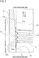
FIG. 2 is an enlarged view showing details of a portion A inFIG. 1 , in which a valve element is shown not cross-sectioned. -
FIG. 3 is a diagram illustratingConventional Art 1; -
FIG. 4 is a diagram illustratingConventional Art 2; and -
FIG. 5 is a diagram illustratingConventional Art 3. - Hereinafter with reference to the drawings, forms for implementing this invention will be described illustratively based on an embodiment. However, the dimensions, materials, shapes, relative arrangements, and others of components described in the embodiment are not intended to limit the scope of the present invention only to them unless otherwise described explicitly.
- With reference to
FIGs. 1 and2 , a displacement control valve according to a first embodiment of the present invention will be described. - A
displacement control valve 1 includes avalve housing 2 formed with a metal material or a resin material, avalve element 15 disposed reciprocably in thevalve housing 2, a pressure-sensitive element 25 biasing thevalve element 15 in one direction, asolenoid 30 as a drive unit connected to thevalve housing 2, for exerting an electromagnetic driving force on thevalve element 15, and others. - The
solenoid 30 includes acasing 31 formed with a metal material coupled to thevalve housing 2, asleeve 32 closed at one end, a cylindrical fixediron core 33 disposed inside of thecasing 31 and thesleeve 32, adriving rod 34 reciprocable in the inside of the fixediron core 33 and coupled to thevalve element 15 at its distal end, amovable iron core 35 fixed to the other end of thedriving rod 34, acoil spring 36 biasing themovable iron core 35 in a direction to open thevalve element 15, anexciting coil 37 wound on the outside of thesleeve 32 via a bobbin, an end member 38 provided in such a manner as to seal an upper end opening of thecasing 31, and others. - The
valve housing 2 includesports ports valve element 15, afirst valve chest 7 formed in the middle of the discharge-side passage, asecond valve chest 8 formed in the middle of the suction-side passage, athird valve chest 9 formed in the discharge-side passage and the suction-side passage, aguide passage 10 for guiding thevalve element 15, and others. Apartition adjustment member 11 demarcating thethird valve chest 9 is pressed in thevalve housing 2. - In the present invention, the discharge-side passage and/or the suction-side passage are sometimes referred to as a "control passage."
- The
port 5 and thethird valve chest 9 are formed to serve as a part of the discharge-side passage and the suction-side passage. Theport 4 forms a valve hole that allows thefirst valve chest 7 and thethird valve chest 9 to communicate, and allows thevalve element 15 to be inserted therethrough (passes thevalve element 15 while providing a gap through which a fluid flows). - In the
first valve chest 7, avalve seat 12 on which afirst valve section 16 of thevalve element 15 described below sits is formed at an edge of the port (valve hole) 4. In thesecond valve chest 8, aseat 33a on which asecond valve section 17 of thevalve element 15 described below sits is formed at an end of the fixediron core 33. - A symbol Ps represents the suction pressure of a variable displacement compressor controlled, Pd the discharge pressure, and Pc the control chamber pressure.
- The
valve element 15 is formed in a substantially cylindrical shape, and includes thefirst valve section 16 on one side, thesecond valve section 17 on the other side, athird valve section 18 coupled opposite to thesecond valve section 17 across thefirst valve section 16 by retrofitting, the communicating path 19 extending therethrough from thesecond valve section 17 to thethird valve section 18 in the axial direction to serve as the suction-side passage, and others. - The
third valve section 18 has a shape expanded from a contracted state from thefirst valve chest 7 to thethird valve chest 9, and is formed with a taperedengaging face 18a facing anadapter 20 at an expanded portion. - The pressure-
sensitive element 25 is disposed in thethird valve chest 9, and operates to exert a biasing force in a direction to open thefirst valve section 16 by its extension (expansion) and to weaken the biasing force exerted on thefirst valve section 16 by contracting with surrounding pressure increase. - As shown in
FIG. 2 , an outer peripheral surface 15a of thevalve element 15 is slidably engaged with aguide surface 10a of theguide passage 10 in thevalve housing 2. - A gap between the outer peripheral surface 15a of the
valve element 15 and theguide surface 10a of theguide passage 10 is in a range of about 0.02 to 0.08 mm, a range that allows impalpable powder X to pass. The dimensions of the gap are set to provide some clearance to thevalve element 15 within a range that prevents the inclination of the axis of thevalve element 15 from becoming excessive so that the surfaces can closely contact each other when thevalve element 15 is seated on thevalve seat 12 to be closed. - At the same time, the gap is designed to have dimensions that allow sealing between the
first valve chest 7 and thesecond valve chest 8 depending on the pressure difference between the discharge pressure Pd of a discharge fluid in the first valve chest 7 (high-pressure side) and the suction pressure Ps in the second valve chest 8 (low-pressure side). - Specifically, the gap has dimensions within a range that limits the discharge fluid under the discharge pressure Pd to a minute leak. A minute leak does not pose a problem much in terms of displacement control.
- In order to reduce sliding resistance of the
valve element 15 during operation, an O-ring for sealing or the like is not provided in the gap between thevalve element 15 and theguide passage 10 in this configuration. - The
valve element 15 is separated from or brought into contact with thevalve seat 12 to open or close it to cause the fluid at the discharge pressure Pd of a high pressure to flow into a crank chamber (control chamber) of the variable displacement compressor not shown as a fluid at the control chamber pressure Pc to control the interior of the crank chamber. - In
FIG. 2 , aspiral groove 22 is provided in the outer peripheral surface 15a of thevalve element 15 facing theguide passage 10. - A tapered
portion 13a is provided at theguide surface 10a of theguide passage 10. - The tapered
portion 13a is set so that the gap between the outer peripheral surface 15a of thevalve element 15 and the inner peripheral surface of theguide passage 10 is larger toward the low-pressure side than on the high-pressure side. - The tapered
portion 13a and thespiral groove 22 are provided so that anaxial starting point 14 of the taperedportion 13a is located within the axial region of thespiral groove 22 in the entire range between the starting point and the ending point of the stroke of thevalve element 15. - In the case of
FIG. 2 , thespiral groove 22 is provided in the outer peripheral surface 15a of thevalve element 15, and the taperedportion 13a is provided at theguide surface 10a of theguide passage 10. On the contrary, a spiral groove may be provided in theguide surface 10a of theguide passage 10, and a tapered portion may be provided at the outer peripheral surface 15a of thevalve element 15. In this case, they are provided so that an axial starting point of the tapered portion at the outer peripheral surface 15a of thevalve element 15 is located within the axial region of the spiral groove in theguide surface 10a of theguide passage 10 in the entire range between the starting point and the ending point of the stroke of thevalve element 15. - In the
displacement control valve 1 configured as described above, the discharge fluid at the discharge pressure Pd flowing into thefirst valve chest 7 flows through theport 4 to thethird valve chest 9 when thevalve element 15 is separated from thevalve seat 12 to be opened. At this time, the discharge pressure Pd is a high pressure, so that a minute amount of fluid also flows toward the gap between the outer peripheral surface 15a of thevalve element 15 and theguide passage 10. However, since the length of astraight portion 13b of theguide passage 10 is within several millimeters, and the pressure of the fluid passing through the gap is high, impalpable powder X contained in the fluid can be prevented from adhering to the sliding surfaces and getting stuck between them. - Then, since the
spiral groove 22 is provided in the outer peripheral surface 15a of thevalve element 15 facing theguide passage 10, the impalpable powder X entering from the high-pressure side toward the low-pressure side axially along thevalve element 15 inevitably crosses thespiral groove 22 in some region on the way, and thus falls into thespiral groove 22. The impalpable powder X that has fallen into thespiral groove 22 is discharged to the low-pressure side by the flow of a fluid flowing through thespiral groove 22. At the same time, thevalve element 15 is aligned by the fluid flowing through thespiral groove 22. - At that time, since the tapered
portion 13a is provided at theguide surface 10a of theguide passage 10 from an axially middle portion of thespiral groove 22, the impalpable powder X is discharged more reliably. - Specifically, the pressure of the fluid in the
spiral groove 22 facing thestraight portion 13b is relatively high because at thestraight portion 13b, the gap is small, and the discharge pressure Pd is acting without being reduced. On the other hand, at the taperedportion 13a, the gap gradually increases toward the low-pressure side, and the pressure of the fluid is gradually reduced due to loss, thus forming a pressure gradient in which the pressure in thespiral groove 22 facing the taperedportion 13a decreases toward the low-pressure side. Therefore, the impalpable powder X that has fallen into thespiral groove 22 facing thestraight portion 13b is forced out immediately without accumulating into thespiral groove 22 facing the taperedportion 13a having the minus pressure gradient, together with the high-pressure fluid, to be discharged to the low-pressure side. Thus, the impalpable powder X is reliably discharged without being accumulated by getting stuck halfway through the gap between the outer peripheral surface 15a of thevalve element 15 and theguide passage 10, or the like. - The displacement control valve in the first embodiment, in which, as described above, the
spiral groove 22 is provided in the outer peripheral surface 15a of thevalve element 15, the taperedportion 13a is provided at theguide surface 10a of theguide passage 10, the taperedportion 13a is set so that the gap between the outer peripheral surface 15a of thevalve element 15 and theguide surface 10a of theguide passage 10 is larger toward the low-pressure side than on the high-pressure side, and the taperedportion 13a and thespiral groove 22 are provided so that thestarting point 14 of the taperedportion 13a is located within the region of thespiral groove 22 in the entire range between the starting point and the ending point of the stroke of thevalve element 15, thus achieves the following outstanding effects. - (1) A fluid flows through the
spiral groove 22 of thevalve element 15, so that the aligning function of thevalve element 15 with respect to thevalve housing 2 is improved, and the operating characteristics of the valve element can be improved, and also formation of a narrower gap portion is prevented, and thus the impalpable powder X can be prevented from getting stuck. Therefore, clearance between the sliding portions can be set small, and the amount of leakage can be reduced, contributing to an improvement in the efficiency of a system such as a car air-conditioner. Further, responsiveness is improved, so that the control speed of a system such as a car air-conditioner can be increased. - (2) The impalpable powder X that has entered the gap between the outer peripheral surface 15a of the
valve element 15 and theguide surface 10a of theguide passage 10 is forced out immediately through thespiral groove 22, thus being discharged reliably to the low-pressure side without accumulating halfway, so that thevalve element 15 can be prevented from increasing its sliding resistance. As a result, the resistance of the displacement control valve to foreign matter is improved, and the displacement control valve maintaining stable operating characteristics can be provided. - Although the embodiment of the present invention has been described above with the drawings, specific configurations are not limited to the embodiment. Any changes and additions made without departing from the scope of the present invention are included in the present invention.
- For example, the above embodiment has been described on the case where the
spiral groove 22 is provided in the outer peripheral surface 15a of thevalve element 15, and the taperedportion 13a is provided at theguide surface 10a of theguide passage 10, which is not limiting. A spiral groove may be provided in theguide surface 10a of theguide passage 10, and a tapered portion may be provided at the outer peripheral surface 15a of thevalve element 15. In this case, an axial starting point of the tapered portion at the outer peripheral surface 15a of thevalve element 15 only needs to be provided in such a manner as to be located within the axial region of the spiral groove in theguide surface 10a of theguide passage 10 in the entire range between the starting point and the ending point of the stroke of thevalve element 15. -
- 1
- displacement control valve
- 2
- valve housing
- 3, 4, 5
- port
- 6
- port
- 7
- first valve chest
- 8
- second valve chest
- 9
- third valve chest
- 10
- guide passage
- 10a
- guide surface
- 11
- partition adjustment member
- 12
- valve seat
- 13a
- tapered portion
- 13b
- straight portion
- 14
- axial starting point of the tapered portion
- 15
- valve element
- 15a
- outer peripheral surface
- 16
- first valve section
- 17
- second valve section
- 18
- third valve section
- 18a
- tapered engaging face
- 19
- communicating path
- 20
- adapter
- 22
- spiral groove
- 25
- pressure-sensitive element
- 30
- solenoid
- 31
- casing
- 32
- sleeve
- 33
- fixed iron core
- 33a
- seat
- 34
- driving rod
- 35
- movable iron core
- 36
- coil spring
- 37
- exciting coil
- 38
- end member
- Pd
- discharge pressure
- Ps
- suction pressure
- Pc
- control chamber pressure
- X
- impalpable powder
Claims (1)
- A displacement control valve comprising a valve housing, a valve element fitted in a guide passage of the valve housing, for opening and closing a control passage, and a solenoid for driving the valve element to open and close the valve element, wherein
a tapered portion is provided at one of an outer peripheral surface of the valve element and a guide surface of the guide passage, and a spiral groove is provided in the other, the tapered portion is set so that a gap between the outer peripheral surface of the valve element and the guide surface of the guide passage is larger toward a low-pressure side than on a high-pressure side, and the tapered portion and the spiral groove are provided so that a starting point of the tapered portion is located within a region of the spiral groove in an entire range between a starting point and an ending point of a stroke of the valve element.
Applications Claiming Priority (2)
| Application Number | Priority Date | Filing Date | Title |
|---|---|---|---|
| JP2014263015 | 2014-12-25 | ||
| PCT/JP2015/085608 WO2016104390A1 (en) | 2014-12-25 | 2015-12-21 | Volume control valve |
Publications (3)
| Publication Number | Publication Date |
|---|---|
| EP3239570A1 true EP3239570A1 (en) | 2017-11-01 |
| EP3239570A4 EP3239570A4 (en) | 2018-08-22 |
| EP3239570B1 EP3239570B1 (en) | 2020-05-13 |
Family
ID=56150409
Family Applications (1)
| Application Number | Title | Priority Date | Filing Date |
|---|---|---|---|
| EP15872958.2A Active EP3239570B1 (en) | 2014-12-25 | 2015-12-21 | Volume control valve |
Country Status (6)
| Country | Link |
|---|---|
| US (1) | US10167978B2 (en) |
| EP (1) | EP3239570B1 (en) |
| JP (1) | JP6756622B2 (en) |
| KR (1) | KR102060433B1 (en) |
| CN (1) | CN107002900B (en) |
| WO (1) | WO2016104390A1 (en) |
Families Citing this family (49)
| Publication number | Priority date | Publication date | Assignee | Title |
|---|---|---|---|---|
| US20150068628A1 (en) * | 2012-05-24 | 2015-03-12 | Eagle Industry Co., Ltd. | Capacity control valve |
| US11603832B2 (en) | 2017-01-26 | 2023-03-14 | Eagle Industry Co., Ltd. | Capacity control valve having a throttle valve portion with a communication hole |
| JP7051238B2 (en) | 2017-02-18 | 2022-04-11 | イーグル工業株式会社 | Capacity control valve |
| US11542931B2 (en) | 2017-11-15 | 2023-01-03 | Eagle Industry Co., Ltd. | Capacity control valve and capacity control valve control method |
| US11512786B2 (en) | 2017-11-30 | 2022-11-29 | Eagle Industry Co., Ltd. | Capacity control valve and control method for capacity control valve |
| JP7086490B2 (en) | 2017-12-08 | 2022-06-20 | イーグル工業株式会社 | Capacity control valve and capacity control valve control method |
| WO2019117225A1 (en) | 2017-12-14 | 2019-06-20 | イーグル工業株式会社 | Capacity control valve and method for controlling capacity control valve |
| US11486376B2 (en) * | 2017-12-27 | 2022-11-01 | Eagle Industry Co., Ltd. | Capacity control valve and method for controlling same |
| EP3734067B1 (en) | 2017-12-27 | 2022-10-26 | Eagle Industry Co., Ltd. | Capacity control valve |
| EP3744976B1 (en) | 2018-01-22 | 2023-06-14 | Eagle Industry Co., Ltd. | Capacity control valve |
| JP6872800B2 (en) * | 2018-01-29 | 2021-05-19 | 株式会社不二工機 | Control valve for variable displacement compressor |
| JP6991890B2 (en) * | 2018-02-23 | 2022-01-13 | イーグル工業株式会社 | Spool valve |
| CN108591597B (en) * | 2018-03-30 | 2019-08-02 | 浙江工贸职业技术学院 | A valve with the ability to prevent impurity from entering |
| EP4148274B1 (en) | 2018-07-12 | 2024-01-17 | Eagle Industry Co., Ltd. | Capacity control valve |
| US11994120B2 (en) | 2018-07-12 | 2024-05-28 | Eagle Industry Co., Ltd. | Capacity control valve |
| US11555489B2 (en) | 2018-07-12 | 2023-01-17 | Eagle Industry Co., Ltd. | Capacity control valve |
| WO2020013169A1 (en) | 2018-07-13 | 2020-01-16 | イーグル工業株式会社 | Capacity control valve |
| US11873805B2 (en) | 2018-08-08 | 2024-01-16 | Eagle Industry Co., Ltd. | Capacity control valve |
| US11473683B2 (en) | 2018-08-08 | 2022-10-18 | Eagle Industry Co., Ltd. | Capacity control valve |
| CN112513460B (en) | 2018-08-08 | 2023-04-28 | 伊格尔工业股份有限公司 | Capacity control valve |
| JP2020067002A (en) * | 2018-10-22 | 2020-04-30 | 株式会社不二工機 | Control valve for variable displacement compressor |
| JP7286672B2 (en) | 2018-11-07 | 2023-06-05 | イーグル工業株式会社 | capacity control valve |
| CN113015853B (en) * | 2018-11-26 | 2022-12-23 | 伊格尔工业股份有限公司 | Capacity control valve |
| JP2020084904A (en) * | 2018-11-28 | 2020-06-04 | 株式会社不二工機 | Control valve for variable displacement compressor |
| EP3892856B1 (en) | 2018-12-04 | 2024-03-27 | Eagle Industry Co., Ltd. | Capacity control valve |
| US12292130B2 (en) | 2019-01-21 | 2025-05-06 | Eagle Industry Co., Ltd. | Capacity control valve |
| WO2020179597A1 (en) * | 2019-03-01 | 2020-09-10 | イーグル工業株式会社 | Capacity control valve |
| JP2020148133A (en) * | 2019-03-13 | 2020-09-17 | 株式会社不二工機 | Control valve for variable capacity type compressor |
| JP2020148134A (en) * | 2019-03-13 | 2020-09-17 | 株式会社不二工機 | Control valve for variable capacity type compressor |
| EP3951173B1 (en) | 2019-04-03 | 2024-06-19 | Eagle Industry Co., Ltd. | Capacity control valve |
| US11927275B2 (en) | 2019-04-03 | 2024-03-12 | Eagle Industry Co., Ltd. | Capacity control valve |
| WO2021060146A1 (en) * | 2019-09-24 | 2021-04-01 | イーグル工業株式会社 | Spool valve |
| DE102019007194A1 (en) * | 2019-10-16 | 2021-04-22 | Vat Holding Ag | Adjustment device for the vacuum range with pressure measurement functionality |
| CN115427684B (en) | 2020-04-23 | 2025-08-05 | 伊格尔工业股份有限公司 | Capacity control valve |
| JPWO2022030309A1 (en) | 2020-08-03 | 2022-02-10 | ||
| JP7673070B2 (en) | 2020-08-04 | 2025-05-08 | イーグル工業株式会社 | valve |
| WO2022030314A1 (en) * | 2020-08-04 | 2022-02-10 | イーグル工業株式会社 | Valve |
| JP7631350B2 (en) | 2020-08-04 | 2025-02-18 | イーグル工業株式会社 | Expansion valve |
| KR102891391B1 (en) | 2020-08-04 | 2025-11-27 | 이구루코교 가부시기가이샤 | valve |
| EP4202265B1 (en) | 2020-08-24 | 2025-12-03 | Eagle Industry Co., Ltd. | Valve |
| KR102879499B1 (en) | 2020-09-28 | 2025-10-31 | 이구루코교 가부시기가이샤 | valve |
| US12276346B2 (en) | 2020-10-01 | 2025-04-15 | Eagle Industry Co., Ltd. | Fluid control valve |
| EP4224032B1 (en) | 2020-10-01 | 2025-12-10 | Eagle Industry Co., Ltd. | Valve |
| EP4265949B1 (en) | 2020-12-17 | 2025-11-19 | Eagle Industry Co., Ltd. | Valve |
| US12510168B2 (en) | 2021-03-29 | 2025-12-30 | Eagle Industry Co., Ltd. | Valve |
| US12435794B2 (en) | 2021-05-31 | 2025-10-07 | Eagle Industry Co., Ltd. | Fluid control valve |
| JPWO2023033143A1 (en) | 2021-09-02 | 2023-03-09 | ||
| CN220168717U (en) * | 2023-06-27 | 2023-12-12 | 比亚迪股份有限公司 | Valve core assembly of electric valve, thermal management system and vehicle |
| CN119900841B (en) * | 2025-04-02 | 2025-07-01 | 迈格发(上海)科技股份有限公司 | Compressor electric control valve |
Family Cites Families (13)
| Publication number | Priority date | Publication date | Assignee | Title |
|---|---|---|---|---|
| DE1550435A1 (en) * | 1966-02-25 | 1970-08-13 | Wilhelm Odendahl | Throttle device |
| JPH11166635A (en) * | 1997-12-02 | 1999-06-22 | Kubota Corp | Bearing structure in valve device |
| JP2000065220A (en) * | 1998-08-12 | 2000-03-03 | Kitz Corp | Control valve |
| JP2001263529A (en) * | 2000-03-16 | 2001-09-26 | Mitsubishi Electric Corp | solenoid valve |
| JP4031945B2 (en) * | 2002-04-09 | 2008-01-09 | サンデン株式会社 | Volume control valve for variable capacity compressor |
| US7104522B2 (en) * | 2002-10-02 | 2006-09-12 | Delphi Technologies, Inc. | Coking-resistant shaft/bushing mechanism for an exhaust gas recirculation valve |
| EP1857748A4 (en) * | 2005-02-28 | 2013-03-13 | Daikin Ind Ltd | EXPANSION VALVE AND REFRIGERATION DEVICE |
| CN100504253C (en) * | 2005-02-28 | 2009-06-24 | 大金工业株式会社 | Expansion valve and refrigeration device |
| CN101466986A (en) * | 2006-06-29 | 2009-06-24 | 大金工业株式会社 | Expansion valve with refrigerant flow dividing structure and refrigeration unit utilizing the same |
| JP4292233B2 (en) * | 2007-05-24 | 2009-07-08 | 株式会社フロント | Flow control valve |
| DE102011077252B4 (en) * | 2011-06-09 | 2018-10-04 | Robert Bosch Gmbh | Valve for controlling a fluid |
| JP5907432B2 (en) * | 2011-06-15 | 2016-04-26 | イーグル工業株式会社 | Capacity control valve |
| US20150068628A1 (en) * | 2012-05-24 | 2015-03-12 | Eagle Industry Co., Ltd. | Capacity control valve |
-
2015
- 2015-12-21 EP EP15872958.2A patent/EP3239570B1/en active Active
- 2015-12-21 KR KR1020177013935A patent/KR102060433B1/en active Active
- 2015-12-21 WO PCT/JP2015/085608 patent/WO2016104390A1/en not_active Ceased
- 2015-12-21 JP JP2016566325A patent/JP6756622B2/en active Active
- 2015-12-21 CN CN201580063934.2A patent/CN107002900B/en active Active
- 2015-12-21 US US15/529,061 patent/US10167978B2/en active Active
Also Published As
| Publication number | Publication date |
|---|---|
| US10167978B2 (en) | 2019-01-01 |
| US20170284562A1 (en) | 2017-10-05 |
| CN107002900A (en) | 2017-08-01 |
| KR102060433B1 (en) | 2019-12-30 |
| EP3239570A4 (en) | 2018-08-22 |
| WO2016104390A1 (en) | 2016-06-30 |
| CN107002900B (en) | 2019-03-12 |
| JPWO2016104390A1 (en) | 2017-10-12 |
| KR20170076739A (en) | 2017-07-04 |
| JP6756622B2 (en) | 2020-09-16 |
| EP3239570B1 (en) | 2020-05-13 |
Similar Documents
| Publication | Publication Date | Title |
|---|---|---|
| EP3239570B1 (en) | Volume control valve | |
| EP3225892B1 (en) | Capacity control valve | |
| EP3835578B1 (en) | Capacity control valve | |
| EP2952741B1 (en) | Variable capacity compressor | |
| US7828264B2 (en) | Flow control valve | |
| EP1845260B1 (en) | Control valve for variable displacement compressor | |
| EP3184817B1 (en) | Variable-capacity compressor control valve | |
| JP2009036182A (en) | Control valve for variable capacity compressor | |
| CN110337555B (en) | Solenoid proportional valve | |
| EP3933197B1 (en) | Capacity control valve | |
| EP3835576B1 (en) | Capacity control valve | |
| EP3835577B1 (en) | Capacity control valve | |
| CN112955684B (en) | Capacity control valve | |
| CN111692345A (en) | Electromagnetic valve | |
| CN111601970B (en) | Volume control valve and control method of volume control valve | |
| KR20230031365A (en) | valve | |
| CN115435088A (en) | electric drive valve |
Legal Events
| Date | Code | Title | Description |
|---|---|---|---|
| STAA | Information on the status of an ep patent application or granted ep patent |
Free format text: STATUS: THE INTERNATIONAL PUBLICATION HAS BEEN MADE |
|
| PUAI | Public reference made under article 153(3) epc to a published international application that has entered the european phase |
Free format text: ORIGINAL CODE: 0009012 |
|
| STAA | Information on the status of an ep patent application or granted ep patent |
Free format text: STATUS: REQUEST FOR EXAMINATION WAS MADE |
|
| 17P | Request for examination filed |
Effective date: 20170529 |
|
| AK | Designated contracting states |
Kind code of ref document: A1 Designated state(s): AL AT BE BG CH CY CZ DE DK EE ES FI FR GB GR HR HU IE IS IT LI LT LU LV MC MK MT NL NO PL PT RO RS SE SI SK SM TR |
|
| AX | Request for extension of the european patent |
Extension state: BA ME |
|
| DAV | Request for validation of the european patent (deleted) | ||
| DAX | Request for extension of the european patent (deleted) | ||
| A4 | Supplementary search report drawn up and despatched |
Effective date: 20180723 |
|
| RIC1 | Information provided on ipc code assigned before grant |
Ipc: G05D 16/20 20060101ALI20180717BHEP Ipc: F16K 25/04 20060101ALI20180717BHEP Ipc: F16K 41/00 20060101ALI20180717BHEP Ipc: F16K 47/12 20060101ALI20180717BHEP Ipc: F16K 51/00 20060101ALI20180717BHEP Ipc: F04B 39/10 20060101ALI20180717BHEP Ipc: F16K 27/02 20060101ALI20180717BHEP Ipc: F16K 31/06 20060101AFI20180717BHEP Ipc: F04B 27/18 20060101ALI20180717BHEP |
|
| STAA | Information on the status of an ep patent application or granted ep patent |
Free format text: STATUS: EXAMINATION IS IN PROGRESS |
|
| 17Q | First examination report despatched |
Effective date: 20190218 |
|
| RIC1 | Information provided on ipc code assigned before grant |
Ipc: F16K 31/06 20060101AFI20191122BHEP Ipc: F04B 27/18 20060101ALI20191122BHEP Ipc: F04B 39/10 20060101ALI20191122BHEP Ipc: F16K 25/04 20060101ALI20191122BHEP Ipc: F16K 41/00 20060101ALI20191122BHEP Ipc: F16K 47/12 20060101ALI20191122BHEP Ipc: G05D 16/20 20060101ALI20191122BHEP Ipc: F16K 27/02 20060101ALI20191122BHEP Ipc: F04B 27/10 20060101ALI20191122BHEP Ipc: F16K 51/00 20060101ALI20191122BHEP |
|
| GRAP | Despatch of communication of intention to grant a patent |
Free format text: ORIGINAL CODE: EPIDOSNIGR1 |
|
| STAA | Information on the status of an ep patent application or granted ep patent |
Free format text: STATUS: GRANT OF PATENT IS INTENDED |
|
| INTG | Intention to grant announced |
Effective date: 20200103 |
|
| GRAS | Grant fee paid |
Free format text: ORIGINAL CODE: EPIDOSNIGR3 |
|
| GRAA | (expected) grant |
Free format text: ORIGINAL CODE: 0009210 |
|
| STAA | Information on the status of an ep patent application or granted ep patent |
Free format text: STATUS: THE PATENT HAS BEEN GRANTED |
|
| AK | Designated contracting states |
Kind code of ref document: B1 Designated state(s): AL AT BE BG CH CY CZ DE DK EE ES FI FR GB GR HR HU IE IS IT LI LT LU LV MC MK MT NL NO PL PT RO RS SE SI SK SM TR |
|
| REG | Reference to a national code |
Ref country code: GB Ref legal event code: FG4D |
|
| REG | Reference to a national code |
Ref country code: CH Ref legal event code: EP |
|
| REG | Reference to a national code |
Ref country code: DE Ref legal event code: R096 Ref document number: 602015052897 Country of ref document: DE |
|
| REG | Reference to a national code |
Ref country code: AT Ref legal event code: REF Ref document number: 1270729 Country of ref document: AT Kind code of ref document: T Effective date: 20200615 |
|
| REG | Reference to a national code |
Ref country code: LT Ref legal event code: MG4D |
|
| REG | Reference to a national code |
Ref country code: NL Ref legal event code: MP Effective date: 20200513 |
|
| PG25 | Lapsed in a contracting state [announced via postgrant information from national office to epo] |
Ref country code: LT Free format text: LAPSE BECAUSE OF FAILURE TO SUBMIT A TRANSLATION OF THE DESCRIPTION OR TO PAY THE FEE WITHIN THE PRESCRIBED TIME-LIMIT Effective date: 20200513 Ref country code: SE Free format text: LAPSE BECAUSE OF FAILURE TO SUBMIT A TRANSLATION OF THE DESCRIPTION OR TO PAY THE FEE WITHIN THE PRESCRIBED TIME-LIMIT Effective date: 20200513 Ref country code: IS Free format text: LAPSE BECAUSE OF FAILURE TO SUBMIT A TRANSLATION OF THE DESCRIPTION OR TO PAY THE FEE WITHIN THE PRESCRIBED TIME-LIMIT Effective date: 20200913 Ref country code: NO Free format text: LAPSE BECAUSE OF FAILURE TO SUBMIT A TRANSLATION OF THE DESCRIPTION OR TO PAY THE FEE WITHIN THE PRESCRIBED TIME-LIMIT Effective date: 20200813 Ref country code: GR Free format text: LAPSE BECAUSE OF FAILURE TO SUBMIT A TRANSLATION OF THE DESCRIPTION OR TO PAY THE FEE WITHIN THE PRESCRIBED TIME-LIMIT Effective date: 20200814 Ref country code: FI Free format text: LAPSE BECAUSE OF FAILURE TO SUBMIT A TRANSLATION OF THE DESCRIPTION OR TO PAY THE FEE WITHIN THE PRESCRIBED TIME-LIMIT Effective date: 20200513 Ref country code: PT Free format text: LAPSE BECAUSE OF FAILURE TO SUBMIT A TRANSLATION OF THE DESCRIPTION OR TO PAY THE FEE WITHIN THE PRESCRIBED TIME-LIMIT Effective date: 20200914 |
|
| PG25 | Lapsed in a contracting state [announced via postgrant information from national office to epo] |
Ref country code: HR Free format text: LAPSE BECAUSE OF FAILURE TO SUBMIT A TRANSLATION OF THE DESCRIPTION OR TO PAY THE FEE WITHIN THE PRESCRIBED TIME-LIMIT Effective date: 20200513 Ref country code: RS Free format text: LAPSE BECAUSE OF FAILURE TO SUBMIT A TRANSLATION OF THE DESCRIPTION OR TO PAY THE FEE WITHIN THE PRESCRIBED TIME-LIMIT Effective date: 20200513 Ref country code: LV Free format text: LAPSE BECAUSE OF FAILURE TO SUBMIT A TRANSLATION OF THE DESCRIPTION OR TO PAY THE FEE WITHIN THE PRESCRIBED TIME-LIMIT Effective date: 20200513 Ref country code: BG Free format text: LAPSE BECAUSE OF FAILURE TO SUBMIT A TRANSLATION OF THE DESCRIPTION OR TO PAY THE FEE WITHIN THE PRESCRIBED TIME-LIMIT Effective date: 20200813 |
|
| REG | Reference to a national code |
Ref country code: AT Ref legal event code: MK05 Ref document number: 1270729 Country of ref document: AT Kind code of ref document: T Effective date: 20200513 |
|
| PG25 | Lapsed in a contracting state [announced via postgrant information from national office to epo] |
Ref country code: NL Free format text: LAPSE BECAUSE OF FAILURE TO SUBMIT A TRANSLATION OF THE DESCRIPTION OR TO PAY THE FEE WITHIN THE PRESCRIBED TIME-LIMIT Effective date: 20200513 Ref country code: AL Free format text: LAPSE BECAUSE OF FAILURE TO SUBMIT A TRANSLATION OF THE DESCRIPTION OR TO PAY THE FEE WITHIN THE PRESCRIBED TIME-LIMIT Effective date: 20200513 |
|
| PG25 | Lapsed in a contracting state [announced via postgrant information from national office to epo] |
Ref country code: ES Free format text: LAPSE BECAUSE OF FAILURE TO SUBMIT A TRANSLATION OF THE DESCRIPTION OR TO PAY THE FEE WITHIN THE PRESCRIBED TIME-LIMIT Effective date: 20200513 Ref country code: CZ Free format text: LAPSE BECAUSE OF FAILURE TO SUBMIT A TRANSLATION OF THE DESCRIPTION OR TO PAY THE FEE WITHIN THE PRESCRIBED TIME-LIMIT Effective date: 20200513 Ref country code: RO Free format text: LAPSE BECAUSE OF FAILURE TO SUBMIT A TRANSLATION OF THE DESCRIPTION OR TO PAY THE FEE WITHIN THE PRESCRIBED TIME-LIMIT Effective date: 20200513 Ref country code: IT Free format text: LAPSE BECAUSE OF FAILURE TO SUBMIT A TRANSLATION OF THE DESCRIPTION OR TO PAY THE FEE WITHIN THE PRESCRIBED TIME-LIMIT Effective date: 20200513 Ref country code: DK Free format text: LAPSE BECAUSE OF FAILURE TO SUBMIT A TRANSLATION OF THE DESCRIPTION OR TO PAY THE FEE WITHIN THE PRESCRIBED TIME-LIMIT Effective date: 20200513 Ref country code: SM Free format text: LAPSE BECAUSE OF FAILURE TO SUBMIT A TRANSLATION OF THE DESCRIPTION OR TO PAY THE FEE WITHIN THE PRESCRIBED TIME-LIMIT Effective date: 20200513 Ref country code: AT Free format text: LAPSE BECAUSE OF FAILURE TO SUBMIT A TRANSLATION OF THE DESCRIPTION OR TO PAY THE FEE WITHIN THE PRESCRIBED TIME-LIMIT Effective date: 20200513 Ref country code: EE Free format text: LAPSE BECAUSE OF FAILURE TO SUBMIT A TRANSLATION OF THE DESCRIPTION OR TO PAY THE FEE WITHIN THE PRESCRIBED TIME-LIMIT Effective date: 20200513 |
|
| REG | Reference to a national code |
Ref country code: DE Ref legal event code: R097 Ref document number: 602015052897 Country of ref document: DE |
|
| PG25 | Lapsed in a contracting state [announced via postgrant information from national office to epo] |
Ref country code: SK Free format text: LAPSE BECAUSE OF FAILURE TO SUBMIT A TRANSLATION OF THE DESCRIPTION OR TO PAY THE FEE WITHIN THE PRESCRIBED TIME-LIMIT Effective date: 20200513 Ref country code: PL Free format text: LAPSE BECAUSE OF FAILURE TO SUBMIT A TRANSLATION OF THE DESCRIPTION OR TO PAY THE FEE WITHIN THE PRESCRIBED TIME-LIMIT Effective date: 20200513 |
|
| PLBE | No opposition filed within time limit |
Free format text: ORIGINAL CODE: 0009261 |
|
| STAA | Information on the status of an ep patent application or granted ep patent |
Free format text: STATUS: NO OPPOSITION FILED WITHIN TIME LIMIT |
|
| 26N | No opposition filed |
Effective date: 20210216 |
|
| PG25 | Lapsed in a contracting state [announced via postgrant information from national office to epo] |
Ref country code: SI Free format text: LAPSE BECAUSE OF FAILURE TO SUBMIT A TRANSLATION OF THE DESCRIPTION OR TO PAY THE FEE WITHIN THE PRESCRIBED TIME-LIMIT Effective date: 20200513 |
|
| REG | Reference to a national code |
Ref country code: CH Ref legal event code: PL |
|
| GBPC | Gb: european patent ceased through non-payment of renewal fee |
Effective date: 20201221 |
|
| PG25 | Lapsed in a contracting state [announced via postgrant information from national office to epo] |
Ref country code: MC Free format text: LAPSE BECAUSE OF FAILURE TO SUBMIT A TRANSLATION OF THE DESCRIPTION OR TO PAY THE FEE WITHIN THE PRESCRIBED TIME-LIMIT Effective date: 20200513 |
|
| REG | Reference to a national code |
Ref country code: BE Ref legal event code: MM Effective date: 20201231 |
|
| PG25 | Lapsed in a contracting state [announced via postgrant information from national office to epo] |
Ref country code: LU Free format text: LAPSE BECAUSE OF NON-PAYMENT OF DUE FEES Effective date: 20201221 Ref country code: IE Free format text: LAPSE BECAUSE OF NON-PAYMENT OF DUE FEES Effective date: 20201221 |
|
| PG25 | Lapsed in a contracting state [announced via postgrant information from national office to epo] |
Ref country code: CH Free format text: LAPSE BECAUSE OF NON-PAYMENT OF DUE FEES Effective date: 20201231 Ref country code: GB Free format text: LAPSE BECAUSE OF NON-PAYMENT OF DUE FEES Effective date: 20201221 Ref country code: LI Free format text: LAPSE BECAUSE OF NON-PAYMENT OF DUE FEES Effective date: 20201231 |
|
| PG25 | Lapsed in a contracting state [announced via postgrant information from national office to epo] |
Ref country code: TR Free format text: LAPSE BECAUSE OF FAILURE TO SUBMIT A TRANSLATION OF THE DESCRIPTION OR TO PAY THE FEE WITHIN THE PRESCRIBED TIME-LIMIT Effective date: 20200513 Ref country code: MT Free format text: LAPSE BECAUSE OF FAILURE TO SUBMIT A TRANSLATION OF THE DESCRIPTION OR TO PAY THE FEE WITHIN THE PRESCRIBED TIME-LIMIT Effective date: 20200513 Ref country code: CY Free format text: LAPSE BECAUSE OF FAILURE TO SUBMIT A TRANSLATION OF THE DESCRIPTION OR TO PAY THE FEE WITHIN THE PRESCRIBED TIME-LIMIT Effective date: 20200513 |
|
| PG25 | Lapsed in a contracting state [announced via postgrant information from national office to epo] |
Ref country code: MK Free format text: LAPSE BECAUSE OF FAILURE TO SUBMIT A TRANSLATION OF THE DESCRIPTION OR TO PAY THE FEE WITHIN THE PRESCRIBED TIME-LIMIT Effective date: 20200513 |
|
| PG25 | Lapsed in a contracting state [announced via postgrant information from national office to epo] |
Ref country code: BE Free format text: LAPSE BECAUSE OF NON-PAYMENT OF DUE FEES Effective date: 20201231 |
|
| PG25 | Lapsed in a contracting state [announced via postgrant information from national office to epo] |
Ref country code: IS Free format text: LAPSE BECAUSE OF NON-PAYMENT OF DUE FEES Effective date: 20200913 |
|
| PGFP | Annual fee paid to national office [announced via postgrant information from national office to epo] |
Ref country code: DE Payment date: 20251028 Year of fee payment: 11 |
|
| PGFP | Annual fee paid to national office [announced via postgrant information from national office to epo] |
Ref country code: FR Payment date: 20251110 Year of fee payment: 11 |