EP3239501A1 - Control device for internal combustion engine - Google Patents
Control device for internal combustion engine Download PDFInfo
- Publication number
- EP3239501A1 EP3239501A1 EP15873300.6A EP15873300A EP3239501A1 EP 3239501 A1 EP3239501 A1 EP 3239501A1 EP 15873300 A EP15873300 A EP 15873300A EP 3239501 A1 EP3239501 A1 EP 3239501A1
- Authority
- EP
- European Patent Office
- Prior art keywords
- throttle valve
- opening degree
- upper limit
- cylinder
- timing
- Prior art date
- Legal status (The legal status is an assumption and is not a legal conclusion. Google has not performed a legal analysis and makes no representation as to the accuracy of the status listed.)
- Granted
Links
- 238000002485 combustion reaction Methods 0.000 title claims abstract description 64
- 239000000446 fuel Substances 0.000 claims abstract description 46
- 238000002347 injection Methods 0.000 claims abstract description 34
- 239000007924 injection Substances 0.000 claims abstract description 34
- 230000007246 mechanism Effects 0.000 claims abstract description 27
- 230000006835 compression Effects 0.000 claims abstract description 25
- 238000007906 compression Methods 0.000 claims abstract description 25
- 230000001965 increasing effect Effects 0.000 claims abstract description 19
- 230000002159 abnormal effect Effects 0.000 abstract description 25
- 239000007789 gas Substances 0.000 description 18
- 230000003247 decreasing effect Effects 0.000 description 10
- 230000008859 change Effects 0.000 description 4
- 238000011144 upstream manufacturing Methods 0.000 description 3
- 206010044048 Tooth missing Diseases 0.000 description 2
- 230000005540 biological transmission Effects 0.000 description 2
- 239000003054 catalyst Substances 0.000 description 2
- 239000002826 coolant Substances 0.000 description 2
- 238000010586 diagram Methods 0.000 description 2
- 238000001914 filtration Methods 0.000 description 2
- 238000009499 grossing Methods 0.000 description 2
- 230000007257 malfunction Effects 0.000 description 2
- 238000000034 method Methods 0.000 description 2
- 230000008569 process Effects 0.000 description 2
- 230000000979 retarding effect Effects 0.000 description 2
- 230000001133 acceleration Effects 0.000 description 1
- 230000008901 benefit Effects 0.000 description 1
- 230000003111 delayed effect Effects 0.000 description 1
- 230000000994 depressogenic effect Effects 0.000 description 1
- 230000001687 destabilization Effects 0.000 description 1
- 230000000694 effects Effects 0.000 description 1
- 230000002708 enhancing effect Effects 0.000 description 1
- 239000000203 mixture Substances 0.000 description 1
- 230000004048 modification Effects 0.000 description 1
- 238000012986 modification Methods 0.000 description 1
- 230000003449 preventive effect Effects 0.000 description 1
- 230000009467 reduction Effects 0.000 description 1
- 239000004065 semiconductor Substances 0.000 description 1
- 230000007704 transition Effects 0.000 description 1
- 238000009834 vaporization Methods 0.000 description 1
- 230000008016 vaporization Effects 0.000 description 1
- 239000002918 waste heat Substances 0.000 description 1
- XLYOFNOQVPJJNP-UHFFFAOYSA-N water Substances O XLYOFNOQVPJJNP-UHFFFAOYSA-N 0.000 description 1
Images

Classifications
-
- F—MECHANICAL ENGINEERING; LIGHTING; HEATING; WEAPONS; BLASTING
- F02—COMBUSTION ENGINES; HOT-GAS OR COMBUSTION-PRODUCT ENGINE PLANTS
- F02D—CONTROLLING COMBUSTION ENGINES
- F02D41/00—Electrical control of supply of combustible mixture or its constituents
- F02D41/0002—Controlling intake air
-
- F—MECHANICAL ENGINEERING; LIGHTING; HEATING; WEAPONS; BLASTING
- F02—COMBUSTION ENGINES; HOT-GAS OR COMBUSTION-PRODUCT ENGINE PLANTS
- F02D—CONTROLLING COMBUSTION ENGINES
- F02D41/00—Electrical control of supply of combustible mixture or its constituents
- F02D41/02—Circuit arrangements for generating control signals
- F02D41/04—Introducing corrections for particular operating conditions
- F02D41/10—Introducing corrections for particular operating conditions for acceleration
-
- F—MECHANICAL ENGINEERING; LIGHTING; HEATING; WEAPONS; BLASTING
- F02—COMBUSTION ENGINES; HOT-GAS OR COMBUSTION-PRODUCT ENGINE PLANTS
- F02D—CONTROLLING COMBUSTION ENGINES
- F02D41/00—Electrical control of supply of combustible mixture or its constituents
- F02D41/22—Safety or indicating devices for abnormal conditions
-
- F—MECHANICAL ENGINEERING; LIGHTING; HEATING; WEAPONS; BLASTING
- F02—COMBUSTION ENGINES; HOT-GAS OR COMBUSTION-PRODUCT ENGINE PLANTS
- F02D—CONTROLLING COMBUSTION ENGINES
- F02D41/00—Electrical control of supply of combustible mixture or its constituents
- F02D41/30—Controlling fuel injection
- F02D41/32—Controlling fuel injection of the low pressure type
- F02D41/34—Controlling fuel injection of the low pressure type with means for controlling injection timing or duration
-
- F—MECHANICAL ENGINEERING; LIGHTING; HEATING; WEAPONS; BLASTING
- F02—COMBUSTION ENGINES; HOT-GAS OR COMBUSTION-PRODUCT ENGINE PLANTS
- F02D—CONTROLLING COMBUSTION ENGINES
- F02D13/00—Controlling the engine output power by varying inlet or exhaust valve operating characteristics, e.g. timing
- F02D13/02—Controlling the engine output power by varying inlet or exhaust valve operating characteristics, e.g. timing during engine operation
- F02D13/0223—Variable control of the intake valves only
- F02D13/0234—Variable control of the intake valves only changing the valve timing only
-
- F—MECHANICAL ENGINEERING; LIGHTING; HEATING; WEAPONS; BLASTING
- F02—COMBUSTION ENGINES; HOT-GAS OR COMBUSTION-PRODUCT ENGINE PLANTS
- F02D—CONTROLLING COMBUSTION ENGINES
- F02D13/00—Controlling the engine output power by varying inlet or exhaust valve operating characteristics, e.g. timing
- F02D13/02—Controlling the engine output power by varying inlet or exhaust valve operating characteristics, e.g. timing during engine operation
- F02D13/0269—Controlling the valves to perform a Miller-Atkinson cycle
-
- F—MECHANICAL ENGINEERING; LIGHTING; HEATING; WEAPONS; BLASTING
- F02—COMBUSTION ENGINES; HOT-GAS OR COMBUSTION-PRODUCT ENGINE PLANTS
- F02D—CONTROLLING COMBUSTION ENGINES
- F02D41/00—Electrical control of supply of combustible mixture or its constituents
- F02D41/0002—Controlling intake air
- F02D2041/002—Controlling intake air by simultaneous control of throttle and variable valve actuation
-
- F—MECHANICAL ENGINEERING; LIGHTING; HEATING; WEAPONS; BLASTING
- F02—COMBUSTION ENGINES; HOT-GAS OR COMBUSTION-PRODUCT ENGINE PLANTS
- F02D—CONTROLLING COMBUSTION ENGINES
- F02D2250/00—Engine control related to specific problems or objectives
- F02D2250/18—Control of the engine output torque
- F02D2250/26—Control of the engine output torque by applying a torque limit
-
- Y—GENERAL TAGGING OF NEW TECHNOLOGICAL DEVELOPMENTS; GENERAL TAGGING OF CROSS-SECTIONAL TECHNOLOGIES SPANNING OVER SEVERAL SECTIONS OF THE IPC; TECHNICAL SUBJECTS COVERED BY FORMER USPC CROSS-REFERENCE ART COLLECTIONS [XRACs] AND DIGESTS
- Y02—TECHNOLOGIES OR APPLICATIONS FOR MITIGATION OR ADAPTATION AGAINST CLIMATE CHANGE
- Y02T—CLIMATE CHANGE MITIGATION TECHNOLOGIES RELATED TO TRANSPORTATION
- Y02T10/00—Road transport of goods or passengers
- Y02T10/10—Internal combustion engine [ICE] based vehicles
- Y02T10/12—Improving ICE efficiencies
-
- Y—GENERAL TAGGING OF NEW TECHNOLOGICAL DEVELOPMENTS; GENERAL TAGGING OF CROSS-SECTIONAL TECHNOLOGIES SPANNING OVER SEVERAL SECTIONS OF THE IPC; TECHNICAL SUBJECTS COVERED BY FORMER USPC CROSS-REFERENCE ART COLLECTIONS [XRACs] AND DIGESTS
- Y02—TECHNOLOGIES OR APPLICATIONS FOR MITIGATION OR ADAPTATION AGAINST CLIMATE CHANGE
- Y02T—CLIMATE CHANGE MITIGATION TECHNOLOGIES RELATED TO TRANSPORTATION
- Y02T10/00—Road transport of goods or passengers
- Y02T10/10—Internal combustion engine [ICE] based vehicles
- Y02T10/40—Engine management systems
Definitions
- the present invention relates to an engine control unit to control an internal combustion engine equipped with a variable valve timing (VVT) mechanism that can vary the opening timing and/or the closing timing of an intake valve.
- VVT variable valve timing
- the Miller cycle (the Atkinson cycle) is cited as a purpose of a WT mechanism. That is, the length of a compression stroke is actually shortened than the length of an expansion stroke by setting the valve timing such that an intake valve opens at a timing after the exhaust top dead center and/or the intake valve closes at a timing after the intake bottom dead center.
- the Miller cycle in which the actual expansion ratio is greater than the actual compression ratio has the advantage of being capable of reducing waste heat and improving thermal efficiency.
- the theoretical compression ratio of a cylinder (the ratio of the volume of its combustion chamber of when a piston reaches the bottom dead center to that of when the piston reaches the top dead center) tends upward.
- Patent document 1 Japanese Unexamined Patent Application Publication No. 2014-125881 .
- an upper limit is placed on the opening degree of a throttle valve, which is a valve for the restriction of intake gas, so as to prevent transition to the operation range at high risk of causing the abnormal combustion.
- the actual compression ratio of the cylinder is influenced by intake valve timing presently achieved.
- intake valve timing is greatly retarded, the risk of causing the abnormal combustion is lowered, hence decreasing the opening degree of the throttle valve does not contribute to preventing the abnormal combustion but only reduces output torque of the internal combustion engine unnecessarily. Therefore it is desirable to adjust the upper limit on the opening degree of the throttle valve according to the intake valve timing presently achieved by the WT mechanism, that is, the actual compression ratio of the cylinder.
- the opening degree of the throttle valve may far surpass the proper upper limit temporarily. In that case, the possibility of causing the abnormal combustion, for example pre-ignition in the cylinder is increased. Moreover, even if a closing operation to decrease the opening degree of the throttle valve to the proper upper limit is executed, a time lag exists between the decreasing of the opening degree of the throttle valve and the decreasing of the amount of the intake gas that actually flows into the cylinder, and there is consequently concern about causing the abnormal combustion in succession until the actual compression ratio of the cylinder falls.
- an engine control unit to control an internal combustion engine equipped with a variable valve timing mechanism that can vary the opening timing and/or the closing timing of an intake valve and alter the actual compression ratio of a cylinder is configured such that the engine control unit sets an upper limit on the opening degree of a throttle valve higher in a situation where the actual compression ratio of the cylinder is high than the upper limit on the opening degree of the throttle valve in a situation where the actual compression ratio of the cylinder is low, the engine control unit amends fuel injection amount to be increased or temporarily stops fuel injection when the current opening degree of the throttle valve is over the upper limit and besides the difference between both of those is enlarged to be greater than or equal to a predetermined value.
- the engine control unit amend fuel injection amount to be increased when the difference between the current opening degree of the throttle valve and the upper limit is less than a threshold, and temporarily stop fuel injection when the difference is greater than or equal to the threshold.
- the present invention is able to prevent causing the abnormal combustion in succession in the cylinder appropriately.
- FIG. 1 shows an overview of an internal combustion engine for a motor vehicle according to the embodiment.
- the internal combustion engine in this embodiment is a four-stroke spark-ignition gasoline engine containing a plurality of cylinders 1 (one of those is illustrated in FIG. 1 ).
- An injector 11 to inject fuel is provided in the neighborhood of an intake port of each cylinder 1.
- a spark plug 12 is installed in a ceiling part of a combustion chamber of each cylinder 1.
- the spark plug 12 to which induced voltage generated in an ignition coil is applied occurs spark discharge between a central electrode and a ground electrode.
- the ignition coil together with an igniter that is a semiconductor switching element, is incorporated in a coil case.
- An exhaust passage 4 to discharge exhaust gas guides the exhaust gas emitted as a result of combustion of the fuel in the cylinders 1 from an exhaust port of each cylinder 1 to the outside.
- An exhaust manifold 42 and a three-way catalyst 41 to clean the exhaust gas up are arranged in this order from the upstream on the exhaust passage 4.
- the internal combustion engine in this embodiment is equipped with a WT mechanism 6 that can perform variable control on the opening and closing timing of an intake valve of each cylinder 1.
- the WT mechanism 6 is already known one (electric-motor-driven WT) that alters rotation phase of an intake camshaft for driving the intake valve of each cylinder 1 relative to a crankshaft with an electric motor. It is well known that the intake camshaft in the internal combustion engine is driven by the crankshaft and rotates, the crankshaft being an output shaft of the internal combustion engine, rotary driving force supplied through the crankshaft being applied to the intake camshaft. A wrapping transmission (not illustrated) to transmit the rotary driving force exists between the crankshaft and the camshaft.
- the wrapping transmission has components including a crankshaft sprocket (or pulley) provided on the crankshaft side, a camshaft sprocket (or pulley) provided on the intake camshaft side, and a timing chain (or belt) wrapped around these sprockets (or pulleys).
- the WT mechanism 6 makes the intake camshaft rotate relatively with the cam sprocket so that the rotation phase of the intake camshaft relative to the crankshaft is altered, thereby the opening and closing timing of the intake valve is varied.
- the internal combustion engine in this embodiment can perform the Miller cycle operation in which the closing timing of the intake valve is retarded to be much later (for example, 55 or over crank-angle degrees later) than the intake bottom dead center.
- the opening timing of the intake valve is retarded up to the approximate exhaust top dead center or a timing slightly later (for example, about 5 crank-angle degrees later) than the exhaust top dead center in the Miller cycle operation.
- An electronic control unit (ECU) 0 that is an engine control unit for the internal combustion engine according to the embodiment is a microcomputer system having a processor, a memory, an input interface, an output interface, and so on.
- Input to the input interface of the ECU 0 are a vehicle speed signal a that is output by a vehicle speed sensor to detect vehicle speed, a crank angle signal b that is output by an engine rotation sensor to detect the rotation angle of the crankshaft and engine speed, an accelerator opening signal c that is output by a sensor to detect the stroke position of an accelerator pedal or the opening degree of the throttle valve 32, which is accelerator opening degree (so to speak, demand load), a coolant temperature signal d that is output by a water temperature sensor to detect the temperature of engine coolant suggesting the temperature of the internal combustion engine, a vibration signal e that is output by a vibration-type knock sensor to detect the amplitude of vibration of a cylinder block including the cylinders 1, an intake gas temperature and pressure signal f that is output by a temperature and pressure sensor to detect the temperature and pressure of the intake gas in the intake passage 3 (particularly, in the surge tank 33), a cam angle signal g that is output by a cam angle sensor at a plurality of cam angles of the intake camshaft,
- the crank angle sensor measures the rotation angle of a rotor that is fixed to the end part of the crankshaft and rotates integrally with the crankshaft. Teeth or protrusions are formed on the rotor at intervals of predetermined degrees along the rotation direction of the crankshaft. Typically the teeth or protrusions are arranged every time the crankshaft rotates by 10 degrees.
- the crank angle sensor facing the outer circumference of the rotor generates a pulse signal on each occasion that the crank angle sensor detects the individual tooth or protrusion passing through the neighborhood of the sensor, the pulse signal constitutes the crank angle signal b. However, the crank angle sensor does not output thirty-six pulses while the crankshaft rotates once.
- Tooth-missing sections each correspond to specific rotation phase angles of the crankshaft. Parts of the pulse train of the crank angle signal b are also missing due to the tooth-missing sections. Based on the missing pulses, it is possible to determine the absolute angle (attitude) of the crankshaft, in other words, the present position of a piston in each cylinder 1.
- the cam angle sensor measures the rotation angle of a rotor that is fixed to the end part of the intake camshaft and rotates integrally with the intake camshaft. Teeth or protrusions are formed on the rotor at intervals of predetermined degrees along the rotation direction of the intake camshaft.
- the cam angle sensor facing the outer circumference of the rotor generates a pulse signal on each occasion that the cam angle sensor detects the individual tooth or protrusion passing through the neighborhood of the sensor, the pulse signal constitutes the cam angle signal g.
- crank angle signal b and the cam angle signal g it is possible not only to discern and determine the present stroke of each cylinder 1 but also to elucidate the present intake valve timing (the advance angle of the intake valve timing) that the WT mechanism 6 achieves.
- Output from the output interface of the ECU 0 are an ignition signal i to the igniter, a fuel injection signal j to the injector 11, an opening operation signal k to the throttle valve 32, an opening operation signal 1 to the EGR valve 23, a control signal n of the intake valve timing to the WT mechanism 6, and so on.
- the processor on the ECU 0 reads and executes programs stored in the memory beforehand, and calculates operation parameters so as to control the operation of the internal combustion engine.
- the ECU 0 receives various information a, b, c, d, e, f, g and h necessary for the operation control of the internal combustion engine through the input interface, perceives the engine speed, and estimates the amount of the intake gas filling the cylinder 1.
- the ECU 0 determines the various operation parameters such as required fuel injection amount, the timing of fuel injection (containing the number of times of injecting the fuel to one combustion), fuel injection pressure, the timing of ignition, required EGR rate (or EGR amount), and the opening and closing timing of the intake valve, based on the engine speed, the amount of the intake gas, and so on.
- the ECU 0 applies the various control signals i, j, k, 1 and n corresponding to the operation parameters through the output interface.
- the throttle valve 32 as an intake throttle valve is usually operated depending on the stroke position of the accelerator pedal by a driver. That is, as the amount of pressing the accelerator pedal is increased, the opening degree of the throttle valve 32 is enlarged.
- the ECU 0 places an upper limit on the opening degree of the throttle valve 32 and, no matter how large the amount of pressing the accelerator pedal is, does not open the throttle valve 32 beyond the upper limit of the opening degree for the sake of preventing the abnormal combustion from occurring.
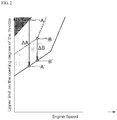
- FIG. 2 exemplifies the upper limit on the opening degree of the throttle valve 32 that the ECU 0 sets.
- An area marked with dots (halftone) in FIG. 2 indicates the operation range at high risk of causing the abnormal combustion such as the pre-ignition.
- the ECU 0 prevents the state of the internal combustion engine from transiting to such operation range by controlling the opening degree of the throttle valve 32 to be smaller than or equal to the upper limit.
- the ECU 0 operates the throttle valve 32 after abolishing the upper limit or setting the upper limit to an opening degree of 100% because it is difficult for the pre-ignition to occur.
- the upper limit on the opening degree of the throttle valve 32 is modified depending on the present opening and closing timing of the intake valve achieved by the WT mechanism 6.
- the intake valve timing While the rotation phase of the intake camshaft relative to the crankshaft is returned to the maximum retarded position with the WT mechanism 6, i.e., the intake valve timing is retarded to the maximum, the intake valve opens at a timing of the approximate exhaust top dead center or at a timing slightly after the exhaust top dead center and closes at a timing delayed greatly from the intake bottom dead center.
- the opening timing of the intake valve becomes before the exhaust top dead center, and besides the closing timing of the intake valve comes near the intake bottom dead center.
- the amount of the intake gas filling the cylinder 1 (and the fuel injection amount) is increased as a result.
- the solid line represents the upper limit on the opening degree of the throttle valve 32 in a situation where the advance amount of the intake valve timing is large
- the dot-dash line represents the upper limit on the opening degree of the throttle valve 32 in a situation where the advance amount of the intake valve timing is small.
- the broken line represents the upper limit on the opening degree of the throttle valve 32 in a situation where the advance amount of the intake valve timing is medium. The upper limit on the opening degree of the throttle valve 32 is higher in the order of the dot-dash line, the broken line, the solid line.
- the ECU 0 hence heightens the upper limit on the opening degree of the throttle valve 32 according to the reduction of the actual compression ratio of the cylinder 1 and enables the throttle valve 32 to open widely even in a low or medium speed range so as to obtain performance that the internal combustion engine originally has.
- the ECU 0 hence lowers the upper limit on the opening degree of the throttle valve 32 according to the enlargement of the actual compression ratio of the cylinder 1 and limits the widening of the throttle valve 32 in the low or medium speed range so as to prevent the pre-ignition or the like from occurring.
- the amount of change of (or the amount of raising) the upper limit per unit time or per unit revolution of the engine (per number of times of expansion strokes in the cylinder 1) be set to be small.
- the amount of change of (or the amount of lowering) the upper limit per unit time or per unit revolution of the engine be set to be larger than the amount of change of (or the amount of raising) the upper limit being heightened. In this way, heightening the upper limit on the opening degree of the throttle valve 32 slowly and lowering the upper limit fast is effective for surely preventing the abnormal combustion.
- the upper limit on the opening degree of the throttle valve 32 is heightened, the upper limit may be determined based on the time series f(t) obtained by a smoothing process (for example, calculating a moving average) or a low-pass filtering of a time series f(t) of the intake valve timing at time t. In this situation, as f(t) is retarded, the upper limit on the opening degree of the throttle valve 32 is heightened.
- the upper limit on the opening degree of the throttle valve 32 is determined based on the intake valve timing f(t) unprocessed with the smoothing process or the low-pass filtering In this situation, needless to say, as f(t) is advanced, the upper limit on the opening degree of the throttle valve 32 is lowered.
- the ECU 0 lowers the upper limit on the opening degree of the throttle valve 32 to the lowest value indicated with the solid line in FIG. 2 immediately in case of detecting that any failure (such as immovableness of the rotation phase of the intake camshaft at the maximum advanced position) occurs in the WT mechanism 6.
- the ECU0 judges that the WT mechanism 6 fails when the state in which the difference between the intake valve timing that the ECU0 gives to the WT mechanism 6 by inputting the control signal n and the actual intake valve timing that the ECU 0 perceives by referring to the crank angle signal b and the cam angle signal g is greater than or equal to a predetermined amount continues for a certain time or a certain number of rotation (or a certain number of expansion strokes in the cylinder 1), for instance.
- the ECU 0 may lower the upper limit on the opening degree of the throttle valve 32 to the lowest value indicated with the solid line in FIG. 2 immediately in case of detecting that the abnormal combustion such as the pre-ignition occurs in the cylinder 1.
- the ECU 0 can judge whether the abnormal combustion occurs in the cylinder 1 or not by referring to the vibration signal e.
- the present opening degree of the throttle valve 32 can temporarily be far higher than the proper upper limit in such cases as the opening and closing timing of the intake valve changes abruptly owing to malfunction of the WT mechanism 6 or other reasons, or occurrence of the abnormal combustion is detected.
- the current operation range of the internal combustion engine is at the point A on the dot-dash line or the point B on the broken line illustrated in FIG. 2
- the rightfully proper upper limit on the opening degree of the throttle valve 32 which is matched with the intake valve timing and is able to avoid causing the abnormal combustion, will be the point A' or the point B' on the solid line. That is, as a sequel to rapidly advancing the intake valve timing, the present opening degree of the throttle valve 32 deviates from the proper upper limit by ⁇ A or ⁇ B.
- the ECU 0 amends the fuel injection amount to be increased or temporarily stops fuel injection, with the decreasing of the opening degree of the throttle valve 32 or in anticipation of the decreasing of the opening degree of the throttle valve 32, when the current opening degree A or B of the throttle valve 32 is over the proper upper limit A' or B' and besides the difference ⁇ A or ⁇ B between both of those is enlarged to be greater than or equal to a predetermined value.
- the fuel cut-off may be carried out only when the current engine speed is greater than or equal to a threshold, otherwise the amendment of the fuel injection amount to be increased may be carried out instead of the fuel cut-off.
- the amendment of the fuel injection amount to be increased or stopping the fuel injection associated with a sudden change in the intake valve timing is ended or the fuel injection is resumed at the time when the opening degree A or B of the throttle valve 32 is decreased to the proper amount A' or B', or after the lapse of a definite period or a definite number of rotation from the time.
- the engine control unit 0 to control the internal combustion engine equipped with the WT mechanism 6 that can vary the opening and closing timing of the intake valve and alter the actual compression ratio of the cylinder 1 is configured such that the engine control unit 0 sets the upper limit on the opening degree of the throttle valve 32 higher in the situation where the actual compression ratio of the cylinder 1 is high than the upper limit on the opening degree of the throttle valve 32 in the situation where the actual compression ratio of the cylinder 1 is low, the engine control unit 0 amends the fuel injection amount to be increased or temporarily stops the fuel injection when the current opening degree of the throttle valve 32 is over the proper upper limit and besides the difference between both of those is enlarged to be greater than or equal to the predetermined value.
- This embodiment makes it possible to prevent causing the abnormal combustion in succession in the cylinder 1 appropriately. Consequently, heightening the upper limit on the opening degree of the throttle valve 32 as much as possible so as to obtain maximum performance that the internal combustion engine originally has and improve acceleration ability of the motor vehicle is enabled.
- the present invention is not limited to the above-described embodiment.
- the specific structure of the WT mechanism 6 to vary the opening timing and/or the closing timing of the intake valve at each cylinder 1 in the internal combustion engine is arbitrary and not particularly limited.
- the WT mechanism that advances/retards the rotation phase of the intake camshaft relative to the crankshaft one that is provided with a plurality of cams to drive and open an intake valve and switches the cams properly, one that alters lever ratio of an rocker arm with an electric motor, one that has an intake valve which is an electromagnetic solenoid valve, and so on are known, selecting and using one from those various mechanisms is allowed.
- the WT mechanism 6 that advances/retards the rotation phase of the intake camshaft relative to the crankshaft varies the opening timing and the closing timing of the intake valve simultaneously. If the VVT mechanism 6 other than one of this kind is provided in the internal combustion engine, the VVT mechanism 6 can vary the opening timing and the closing timing of the intake valve separately, vary the opening timing only, or vary the closing timing only. Thereby the advance amount of the opening timing of the intake valve from the maximum retarded timing may differ from the advance amount of the closing timing of the same intake valve from the maximum retarded timing.
- the present invention is applicable to controlling of internal combustion engines to be mounted on cars or the like.
Landscapes
- Engineering & Computer Science (AREA)
- Chemical & Material Sciences (AREA)
- Combustion & Propulsion (AREA)
- Mechanical Engineering (AREA)
- General Engineering & Computer Science (AREA)
- Output Control And Ontrol Of Special Type Engine (AREA)
- Combined Controls Of Internal Combustion Engines (AREA)
- Electrical Control Of Air Or Fuel Supplied To Internal-Combustion Engine (AREA)
Abstract
Description
- The present invention relates to an engine control unit to control an internal combustion engine equipped with a variable valve timing (VVT) mechanism that can vary the opening timing and/or the closing timing of an intake valve.
- With respect to internal combustion engines to be mounted on cars or the like, ones including WT mechanisms that can perform variable control on the opening and closing timing of intake valves are publicly known (See following Patent Document, for example).
- Realization of the Miller cycle (the Atkinson cycle) is cited as a purpose of a WT mechanism. That is, the length of a compression stroke is actually shortened than the length of an expansion stroke by setting the valve timing such that an intake valve opens at a timing after the exhaust top dead center and/or the intake valve closes at a timing after the intake bottom dead center. The Miller cycle in which the actual expansion ratio is greater than the actual compression ratio has the advantage of being capable of reducing waste heat and improving thermal efficiency.
- In an internal combustion engine performing the Miller cycle operation, the theoretical compression ratio of a cylinder (the ratio of the volume of its combustion chamber of when a piston reaches the bottom dead center to that of when the piston reaches the top dead center) tends upward.
- Patent document 1: Japanese Unexamined Patent Application Publication No.
2014-125881 - The risk of causing abnormal combustion like pre-ignition or heavy knocking in a cylinder of an internal combustion engine now raises because of enhancing the compression ratio. This kind of abnormal combustion easily occurs in a low speed and high load operation range in which engine speed is low but an accelerator is widely open.
- Accordingly it is conceivable to take the preventive measure in that an upper limit is placed on the opening degree of a throttle valve, which is a valve for the restriction of intake gas, so as to prevent transition to the operation range at high risk of causing the abnormal combustion. The actual compression ratio of the cylinder is influenced by intake valve timing presently achieved. When the intake valve timing is greatly retarded, the risk of causing the abnormal combustion is lowered, hence decreasing the opening degree of the throttle valve does not contribute to preventing the abnormal combustion but only reduces output torque of the internal combustion engine unnecessarily. Therefore it is desirable to adjust the upper limit on the opening degree of the throttle valve according to the intake valve timing presently achieved by the WT mechanism, that is, the actual compression ratio of the cylinder.
- In case malfunction of the WT mechanism or another incident that suddenly changes the intake valve timing occurs, the opening degree of the throttle valve may far surpass the proper upper limit temporarily. In that case, the possibility of causing the abnormal combustion, for example pre-ignition in the cylinder is increased. Moreover, even if a closing operation to decrease the opening degree of the throttle valve to the proper upper limit is executed, a time lag exists between the decreasing of the opening degree of the throttle valve and the decreasing of the amount of the intake gas that actually flows into the cylinder, and there is consequently concern about causing the abnormal combustion in succession until the actual compression ratio of the cylinder falls.
- It is an object of the present invention, which first pays attention to the above points, to prevent causing the abnormal combustion in succession appropriately.
- According to the present invention, an engine control unit to control an internal combustion engine equipped with a variable valve timing mechanism that can vary the opening timing and/or the closing timing of an intake valve and alter the actual compression ratio of a cylinder is configured such that the engine control unit sets an upper limit on the opening degree of a throttle valve higher in a situation where the actual compression ratio of the cylinder is high than the upper limit on the opening degree of the throttle valve in a situation where the actual compression ratio of the cylinder is low, the engine control unit amends fuel injection amount to be increased or temporarily stops fuel injection when the current opening degree of the throttle valve is over the upper limit and besides the difference between both of those is enlarged to be greater than or equal to a predetermined value.
- More specifically, it is preferable that the engine control unit amend fuel injection amount to be increased when the difference between the current opening degree of the throttle valve and the upper limit is less than a threshold, and temporarily stop fuel injection when the difference is greater than or equal to the threshold.
- The present invention is able to prevent causing the abnormal combustion in succession in the cylinder appropriately.
-
-
FIG. 1 is a diagram showing a schematic structure of an internal combustion engine and an control unit according to an embodiment of the present invention. -
FIG. 2 is a diagram showing the relationship of upper limits on the opening degree of a throttle valve set by the control unit according to the embodiment with engine speed and intake valve timing. - Described below is an embodiment of the present invention with reference to drawings.
FIG. 1 shows an overview of an internal combustion engine for a motor vehicle according to the embodiment. The internal combustion engine in this embodiment is a four-stroke spark-ignition gasoline engine containing a plurality of cylinders 1 (one of those is illustrated inFIG. 1 ). An injector 11 to inject fuel is provided in the neighborhood of an intake port of each cylinder 1. Also, aspark plug 12 is installed in a ceiling part of a combustion chamber of each cylinder 1. Thespark plug 12 to which induced voltage generated in an ignition coil is applied occurs spark discharge between a central electrode and a ground electrode. The ignition coil, together with an igniter that is a semiconductor switching element, is incorporated in a coil case. - An
intake passage 3 to provide intake gas takes air in from the outside and guides it to the intake port of each cylinder 1. Anair cleaner 31, anelectronic throttle valve 32, asurge tank 33, and anintake manifold 34 are arranged in this order from the upstream on theintake passage 3. - An exhaust passage 4 to discharge exhaust gas guides the exhaust gas emitted as a result of combustion of the fuel in the cylinders 1 from an exhaust port of each cylinder 1 to the outside. An exhaust manifold 42 and a three-
way catalyst 41 to clean the exhaust gas up are arranged in this order from the upstream on the exhaust passage 4. - An exhaust gas recirculation (EGR) device 2 that makes what is called high-pressure-loop EGR has components including an
external EGR passage 21 to connect an upper side from thecatalyst 41 in the exhaust passage 4 to a lower side from thethrottle valve 32 in theintake passage 3, anEGR cooler 22 provided on theEGR passage 21, and anEGR valve 23 to open and shut theEGR passage 21 so as to control the amount of EGR gas flowing through theEGR passage 21. The inlet of the EGRpassage 21 is connected to the exhaust manifold 42 or a predetermined position downstream from it in the exhaust passage 4. The outlet of the EGRpassage 21 is connected to a predetermined position upstream from thethrottle valve 32, particularly thesurge tank 33 in theintake passage 3. - The internal combustion engine in this embodiment is equipped with a
WT mechanism 6 that can perform variable control on the opening and closing timing of an intake valve of each cylinder 1. TheWT mechanism 6 is already known one (electric-motor-driven WT) that alters rotation phase of an intake camshaft for driving the intake valve of each cylinder 1 relative to a crankshaft with an electric motor. It is well known that the intake camshaft in the internal combustion engine is driven by the crankshaft and rotates, the crankshaft being an output shaft of the internal combustion engine, rotary driving force supplied through the crankshaft being applied to the intake camshaft. A wrapping transmission (not illustrated) to transmit the rotary driving force exists between the crankshaft and the camshaft. The wrapping transmission has components including a crankshaft sprocket (or pulley) provided on the crankshaft side, a camshaft sprocket (or pulley) provided on the intake camshaft side, and a timing chain (or belt) wrapped around these sprockets (or pulleys). TheWT mechanism 6 makes the intake camshaft rotate relatively with the cam sprocket so that the rotation phase of the intake camshaft relative to the crankshaft is altered, thereby the opening and closing timing of the intake valve is varied. - According to need, the internal combustion engine in this embodiment can perform the Miller cycle operation in which the closing timing of the intake valve is retarded to be much later (for example, 55 or over crank-angle degrees later) than the intake bottom dead center. The opening timing of the intake valve is retarded up to the approximate exhaust top dead center or a timing slightly later (for example, about 5 crank-angle degrees later) than the exhaust top dead center in the Miller cycle operation.
- An electronic control unit (ECU) 0 that is an engine control unit for the internal combustion engine according to the embodiment is a microcomputer system having a processor, a memory, an input interface, an output interface, and so on.
- Input to the input interface of the ECU 0 are a vehicle speed signal a that is output by a vehicle speed sensor to detect vehicle speed, a crank angle signal b that is output by an engine rotation sensor to detect the rotation angle of the crankshaft and engine speed, an accelerator opening signal c that is output by a sensor to detect the stroke position of an accelerator pedal or the opening degree of the
throttle valve 32, which is accelerator opening degree (so to speak, demand load), a coolant temperature signal d that is output by a water temperature sensor to detect the temperature of engine coolant suggesting the temperature of the internal combustion engine, a vibration signal e that is output by a vibration-type knock sensor to detect the amplitude of vibration of a cylinder block including the cylinders 1, an intake gas temperature and pressure signal f that is output by a temperature and pressure sensor to detect the temperature and pressure of the intake gas in the intake passage 3 (particularly, in the surge tank 33), a cam angle signal g that is output by a cam angle sensor at a plurality of cam angles of the intake camshaft, a brake signal h that is output by a sensor (such as a break switch, a master-cylinder pressure sensor) to detect the fact a brake pedal is depressed or the stroke position of the brake pedal, and so on. - The crank angle sensor measures the rotation angle of a rotor that is fixed to the end part of the crankshaft and rotates integrally with the crankshaft. Teeth or protrusions are formed on the rotor at intervals of predetermined degrees along the rotation direction of the crankshaft. Typically the teeth or protrusions are arranged every time the crankshaft rotates by 10 degrees. The crank angle sensor facing the outer circumference of the rotor generates a pulse signal on each occasion that the crank angle sensor detects the individual tooth or protrusion passing through the neighborhood of the sensor, the pulse signal constitutes the crank angle signal b. However, the crank angle sensor does not output thirty-six pulses while the crankshaft rotates once. Some of the teeth or protrusions of the rotor on the crankshaft are missing. Tooth-missing sections each correspond to specific rotation phase angles of the crankshaft. Parts of the pulse train of the crank angle signal b are also missing due to the tooth-missing sections. Based on the missing pulses, it is possible to determine the absolute angle (attitude) of the crankshaft, in other words, the present position of a piston in each cylinder 1.
- Moreover, the cam angle sensor measures the rotation angle of a rotor that is fixed to the end part of the intake camshaft and rotates integrally with the intake camshaft. Teeth or protrusions are formed on the rotor at intervals of predetermined degrees along the rotation direction of the intake camshaft. The cam angle sensor facing the outer circumference of the rotor generates a pulse signal on each occasion that the cam angle sensor detects the individual tooth or protrusion passing through the neighborhood of the sensor, the pulse signal constitutes the cam angle signal g. By referring to both the crank angle signal b and the cam angle signal g, it is possible not only to discern and determine the present stroke of each cylinder 1 but also to elucidate the present intake valve timing (the advance angle of the intake valve timing) that the
WT mechanism 6 achieves. - Output from the output interface of the ECU 0 are an ignition signal i to the igniter, a fuel injection signal j to the injector 11, an opening operation signal k to the
throttle valve 32, an opening operation signal 1 to theEGR valve 23, a control signal n of the intake valve timing to theWT mechanism 6, and so on. - The processor on the ECU 0 reads and executes programs stored in the memory beforehand, and calculates operation parameters so as to control the operation of the internal combustion engine. The ECU 0 receives various information a, b, c, d, e, f, g and h necessary for the operation control of the internal combustion engine through the input interface, perceives the engine speed, and estimates the amount of the intake gas filling the cylinder 1. Then, the ECU 0 determines the various operation parameters such as required fuel injection amount, the timing of fuel injection (containing the number of times of injecting the fuel to one combustion), fuel injection pressure, the timing of ignition, required EGR rate (or EGR amount), and the opening and closing timing of the intake valve, based on the engine speed, the amount of the intake gas, and so on. The ECU 0 applies the various control signals i, j, k, 1 and n corresponding to the operation parameters through the output interface.
- The
throttle valve 32 as an intake throttle valve is usually operated depending on the stroke position of the accelerator pedal by a driver. That is, as the amount of pressing the accelerator pedal is increased, the opening degree of thethrottle valve 32 is enlarged. However, there is concern about causing abnormal combustion like pre-ignition or heavy knocking in succession due to opening thethrottle valve 32 widely when the engine speed is low, in other words, when movement velocity of the piston in each cylinder 1 is slow. Therefore the ECU 0 according to the embodiment places an upper limit on the opening degree of thethrottle valve 32 and, no matter how large the amount of pressing the accelerator pedal is, does not open thethrottle valve 32 beyond the upper limit of the opening degree for the sake of preventing the abnormal combustion from occurring. -
FIG. 2 exemplifies the upper limit on the opening degree of thethrottle valve 32 that the ECU 0 sets. Basically, the lower the engine speed becomes, the lower the upper limit on the opening degree of thethrottle valve 32 is set to be. An area marked with dots (halftone) inFIG. 2 indicates the operation range at high risk of causing the abnormal combustion such as the pre-ignition. The ECU 0 prevents the state of the internal combustion engine from transiting to such operation range by controlling the opening degree of thethrottle valve 32 to be smaller than or equal to the upper limit. When the engine speed becomes rather high, the ECU 0 operates thethrottle valve 32 after abolishing the upper limit or setting the upper limit to an opening degree of 100% because it is difficult for the pre-ignition to occur. - On top of that, in this embodiment, the upper limit on the opening degree of the
throttle valve 32 is modified depending on the present opening and closing timing of the intake valve achieved by theWT mechanism 6. - While the rotation phase of the intake camshaft relative to the crankshaft is returned to the maximum retarded position with the
WT mechanism 6, i.e., the intake valve timing is retarded to the maximum, the intake valve opens at a timing of the approximate exhaust top dead center or at a timing slightly after the exhaust top dead center and closes at a timing delayed greatly from the intake bottom dead center. As the rotation phase of the intake camshaft relative to the crankshaft is advanced from the maximum retarded position, the opening timing of the intake valve becomes before the exhaust top dead center, and besides the closing timing of the intake valve comes near the intake bottom dead center. The amount of the intake gas filling the cylinder 1 (and the fuel injection amount) is increased as a result. - The smaller the advance amount of the intake valve timing from the maximum retarded timing is, the more the ECU 0 heightens the upper limit on the opening degree of the throttle valve 32 (or eases the limitation on the opening degree of the throttle valve 32) so as to expand the movable range of the
throttle valve 32. InFIG. 2 , the solid line represents the upper limit on the opening degree of thethrottle valve 32 in a situation where the advance amount of the intake valve timing is large, the dot-dash line represents the upper limit on the opening degree of thethrottle valve 32 in a situation where the advance amount of the intake valve timing is small. Also, the broken line represents the upper limit on the opening degree of thethrottle valve 32 in a situation where the advance amount of the intake valve timing is medium. The upper limit on the opening degree of thethrottle valve 32 is higher in the order of the dot-dash line, the broken line, the solid line. - As the advance amount of the intake valve timing is reduced, the closing timing of the intake valve is retarded, the actual compression ratio of the cylinder 1 is lowered, the amount of the intake gas filling the cylinder 1 is decreased. This means that the risk of causing the pre-ignition or the like in the cylinder 1 is reduced. The ECU 0 hence heightens the upper limit on the opening degree of the
throttle valve 32 according to the reduction of the actual compression ratio of the cylinder 1 and enables thethrottle valve 32 to open widely even in a low or medium speed range so as to obtain performance that the internal combustion engine originally has. - In contrast, as the advance amount of the intake valve timing is enlarged, the closing timing of the intake valve is advanced, the actual compression ratio of the cylinder 1 is heightened, the amount of the intake gas filling the cylinder 1 is increased. This means that the risk of causing the pre-ignition or the like in the cylinder 1 is enlarged. The ECU 0 hence lowers the upper limit on the opening degree of the
throttle valve 32 according to the enlargement of the actual compression ratio of the cylinder 1 and limits the widening of thethrottle valve 32 in the low or medium speed range so as to prevent the pre-ignition or the like from occurring. - While the upper limit on the opening degree of the
throttle valve 32 is heightened, it is preferable that the amount of change of (or the amount of raising) the upper limit per unit time or per unit revolution of the engine (per number of times of expansion strokes in the cylinder 1) be set to be small. On the other hand, while the upper limit on the opening degree of thethrottle valve 32 is lowered, it is preferable that the amount of change of (or the amount of lowering) the upper limit per unit time or per unit revolution of the engine be set to be larger than the amount of change of (or the amount of raising) the upper limit being heightened. In this way, heightening the upper limit on the opening degree of thethrottle valve 32 slowly and lowering the upper limit fast is effective for surely preventing the abnormal combustion. - While the upper limit on the opening degree of the
throttle valve 32 is heightened, the upper limit may be determined based on the time series f(t) obtained by a smoothing process (for example, calculating a moving average) or a low-pass filtering of a time series f(t) of the intake valve timing at time t. In this situation, as f(t) is retarded, the upper limit on the opening degree of thethrottle valve 32 is heightened. In contrast to that, while the upper limit on the opening degree of thethrottle valve 32 is lowered, the upper limit is determined based on the intake valve timing f(t) unprocessed with the smoothing process or the low-pass filtering In this situation, needless to say, as f(t) is advanced, the upper limit on the opening degree of thethrottle valve 32 is lowered. - It is noted that the ECU 0 lowers the upper limit on the opening degree of the
throttle valve 32 to the lowest value indicated with the solid line inFIG. 2 immediately in case of detecting that any failure (such as immovableness of the rotation phase of the intake camshaft at the maximum advanced position) occurs in theWT mechanism 6. The ECU0 judges that theWT mechanism 6 fails when the state in which the difference between the intake valve timing that the ECU0 gives to theWT mechanism 6 by inputting the control signal n and the actual intake valve timing that the ECU 0 perceives by referring to the crank angle signal b and the cam angle signal g is greater than or equal to a predetermined amount continues for a certain time or a certain number of rotation (or a certain number of expansion strokes in the cylinder 1), for instance. - The ECU 0 may lower the upper limit on the opening degree of the
throttle valve 32 to the lowest value indicated with the solid line inFIG. 2 immediately in case of detecting that the abnormal combustion such as the pre-ignition occurs in the cylinder 1. The ECU 0 can judge whether the abnormal combustion occurs in the cylinder 1 or not by referring to the vibration signal e. - By the way, the present opening degree of the
throttle valve 32 can temporarily be far higher than the proper upper limit in such cases as the opening and closing timing of the intake valve changes abruptly owing to malfunction of theWT mechanism 6 or other reasons, or occurrence of the abnormal combustion is detected. For example, when the current operation range of the internal combustion engine is at the point A on the dot-dash line or the point B on the broken line illustrated inFIG. 2 , if the intake valve timing is rapidly advanced by an advance amount corresponding to the solid line, the rightfully proper upper limit on the opening degree of thethrottle valve 32, which is matched with the intake valve timing and is able to avoid causing the abnormal combustion, will be the point A' or the point B' on the solid line. That is, as a sequel to rapidly advancing the intake valve timing, the present opening degree of thethrottle valve 32 deviates from the proper upper limit by ΔA or ΔB. - Of course, while the intake valve timing is advanced in that manner, an operation is executed such that the opening degree of the
throttle valve 32 is decreased from the point A to the point A', or from the point B to the point B'. However, a time lag exists between the decreasing of the opening degree of thethrottle valve 32 and the decreasing of the amount of the intake gas that actually flows into the cylinder 1, thereby there is concern about causing the abnormal combustion in succession until the actual compression ratio of the cylinder 1 falls actually. - In order to prevent causing the abnormal combustion in succession appropriately, the ECU 0 according to the embodiment amends the fuel injection amount to be increased or temporarily stops fuel injection, with the decreasing of the opening degree of the
throttle valve 32 or in anticipation of the decreasing of the opening degree of thethrottle valve 32, when the current opening degree A or B of thethrottle valve 32 is over the proper upper limit A' or B' and besides the difference ΔA or ΔB between both of those is enlarged to be greater than or equal to a predetermined value. - Increasing of the fuel injection amount so that the air-fuel ratio of a mixture gets rich yields a temperature fall inside the combustion chamber of the cylinder 1 by heat of vaporization or latent heat of the fuel and reduces the risk of causing the abnormal combustion such as the pre-ignition. Also, a fuel cut-off to interrupt the fuel injection is obviously conducive to avoidance of the abnormal combustion.
- The influence of stopping the fuel injection temporarily upon engine torque that the internal combustion engine outputs is naturally greater than that of amending the fuel injection amount to be increased. Therefore it is desirable to elect to amend the fuel injection amount to be increased when the difference ΔA or ΔB between the current opening degree A or B of the
throttle valve 32 and the proper upper limit A' or B' is less than a threshold, and elect to temporarily stop the fuel injection when the difference ΔA or ΔB is greater than or equal to the threshold, through comparing the difference ΔA or ΔB with the threshold. According to the example illustrated inFIG. 2 , the fuel cut-off to temporarily stop the fuel injection is carried out in a situation where the current opening degree of thethrottle valve 32 is at the point A and the difference ΔA from the proper upper limit A' is comparatively large. In contrast, the amendment of the fuel injection amount to be increased so that the air-fuel ratio gets rich is carried out in a situation where the current opening degree of thethrottle valve 32 is at the point B and the difference ΔB from the proper upper limit B' is comparatively small. - Other than the above, it is possible to elect to amend the fuel injection amount to be increased when the current opening degree A or B of the
throttle valve 32, in other words the engine load itself, is less than a threshold, and elect to temporarily stop the fuel injection when the current opening degree A or B is greater than or equal to the threshold, through comparing the current opening degree A or B with the threshold. Since the possibility cannot be denied that the fuel cut-off causes a destabilization of engine rotation or an engine stall, the fuel cut-off may be carried out only when the current engine speed is greater than or equal to a threshold, otherwise the amendment of the fuel injection amount to be increased may be carried out instead of the fuel cut-off. - After the amendment of the fuel injection amount to be increased or stopping the fuel injection associated with a sudden change in the intake valve timing, the amendment of the fuel injection amount to be increased is ended or the fuel injection is resumed at the time when the opening degree A or B of the
throttle valve 32 is decreased to the proper amount A' or B', or after the lapse of a definite period or a definite number of rotation from the time. - According to the embodiment, the engine control unit 0 to control the internal combustion engine equipped with the
WT mechanism 6 that can vary the opening and closing timing of the intake valve and alter the actual compression ratio of the cylinder 1 is configured such that the engine control unit 0 sets the upper limit on the opening degree of thethrottle valve 32 higher in the situation where the actual compression ratio of the cylinder 1 is high than the upper limit on the opening degree of thethrottle valve 32 in the situation where the actual compression ratio of the cylinder 1 is low, the engine control unit 0 amends the fuel injection amount to be increased or temporarily stops the fuel injection when the current opening degree of thethrottle valve 32 is over the proper upper limit and besides the difference between both of those is enlarged to be greater than or equal to the predetermined value. - This embodiment makes it possible to prevent causing the abnormal combustion in succession in the cylinder 1 appropriately. Consequently, heightening the upper limit on the opening degree of the
throttle valve 32 as much as possible so as to obtain maximum performance that the internal combustion engine originally has and improve acceleration ability of the motor vehicle is enabled. - The present invention is not limited to the above-described embodiment. In particular, the specific structure of the
WT mechanism 6 to vary the opening timing and/or the closing timing of the intake valve at each cylinder 1 in the internal combustion engine is arbitrary and not particularly limited. Other than the WT mechanism that advances/retards the rotation phase of the intake camshaft relative to the crankshaft, one that is provided with a plurality of cams to drive and open an intake valve and switches the cams properly, one that alters lever ratio of an rocker arm with an electric motor, one that has an intake valve which is an electromagnetic solenoid valve, and so on are known, selecting and using one from those various mechanisms is allowed. - The
WT mechanism 6 that advances/retards the rotation phase of the intake camshaft relative to the crankshaft varies the opening timing and the closing timing of the intake valve simultaneously. If theVVT mechanism 6 other than one of this kind is provided in the internal combustion engine, theVVT mechanism 6 can vary the opening timing and the closing timing of the intake valve separately, vary the opening timing only, or vary the closing timing only. Thereby the advance amount of the opening timing of the intake valve from the maximum retarded timing may differ from the advance amount of the closing timing of the same intake valve from the maximum retarded timing. - It is possible to increase/decrease the amount of the intake gas filling the combustion chamber of the cylinder 1 by advancing/retarding the closing timing of the intake valve only. In respect to the internal combustion engine that can perform the Miller cycle operation in which the opening timing of the intake valve is retarded to be much later than the exhaust top dead center, it is possible to increase/decrease the amount of the intake gas filling the combustion chamber of the cylinder 1 by advancing/retarding the opening timing of the intake valve only. For these cases, similarly to the above embodiment, the upper limit on the opening degree of the
throttle valve 32 can be adjusted depending on (the advance amount of) the opening timing or the closing timing of the intake valve. That is, the lower the actual compression ratio of the cylinder 1 is, the higher the upper limit on the opening degree of thethrottle valve 32 gets. - Further, the means of detecting the abnormal combustion such as the pre-ignition is not limited to the vibration-type knock sensor. For example, it is possible to judge whether the abnormal combustion occurs or not by detecting an ion current that flows in the electrode of the
spark plug 12 when the fuel is combusted inside the combustion chamber of the cylinder 1 and referring to the wave form of the ion current signal. - In addition, regarding to the concrete configurations of the respective components, various modifications are possible without departing from the scope and spirit of the present invention.
- The present invention is applicable to controlling of internal combustion engines to be mounted on cars or the like.
-
- 0
- engine control unit (ECU)
- 1
- cylinder
- 11
- injector
- 32
- throttle valve
- 5
- pilot valve part
- 6
- variable valve timing (VVT) mechanism
- b
- crank angle signal
- c
- accelerator opening signal
- e
- vibration signal
- g
- cam angle signal
- k
- opening operation signal
- n
- control signal of intake valve timing
Claims (2)
- An engine control unit to control an internal combustion engine equipped with a variable valve timing mechanism that can vary the opening timing or the closing timing of an intake valve and alter the actual compression ratio of a cylinder, wherein
the engine control unit sets an upper limit on the opening degree of a throttle valve higher in a situation where the actual compression ratio of the cylinder is high than the upper limit on the opening degree of the throttle valve in a situation where the actual compression ratio of the cylinder is low,
the engine control unit amends fuel injection amount to be increased or temporarily stops fuel injection when the current opening degree of the throttle valve is over the upper limit and besides the difference between both of those is enlarged to be greater than or equal to a predetermined value. - The engine control unit according to claim 1, wherein
the engine control unit amends fuel injection amount to be increased when the difference between the current opening degree of the throttle valve and the upper limit is less than a threshold,
the engine control unit temporarily stops fuel injection when the difference is greater than or equal to the threshold.
Applications Claiming Priority (2)
| Application Number | Priority Date | Filing Date | Title |
|---|---|---|---|
| JP2014263220A JP6450587B2 (en) | 2014-12-25 | 2014-12-25 | Control device for internal combustion engine |
| PCT/JP2015/086297 WO2016104732A1 (en) | 2014-12-25 | 2015-12-25 | Control device for internal combustion engine |
Publications (3)
| Publication Number | Publication Date |
|---|---|
| EP3239501A1 true EP3239501A1 (en) | 2017-11-01 |
| EP3239501A4 EP3239501A4 (en) | 2018-08-29 |
| EP3239501B1 EP3239501B1 (en) | 2019-10-30 |
Family
ID=56150744
Family Applications (1)
| Application Number | Title | Priority Date | Filing Date |
|---|---|---|---|
| EP15873300.6A Not-in-force EP3239501B1 (en) | 2014-12-25 | 2015-12-25 | Control device for internal combustion engine |
Country Status (4)
| Country | Link |
|---|---|
| EP (1) | EP3239501B1 (en) |
| JP (1) | JP6450587B2 (en) |
| CN (1) | CN106030081B (en) |
| WO (1) | WO2016104732A1 (en) |
Families Citing this family (2)
| Publication number | Priority date | Publication date | Assignee | Title |
|---|---|---|---|---|
| MX2020001705A (en) * | 2017-08-31 | 2020-07-14 | Nissan Motor | Control method and control device for internal combustion engine. |
| JP7567846B2 (en) * | 2022-03-25 | 2024-10-16 | トヨタ自動車株式会社 | Engine Control Unit |
Family Cites Families (16)
| Publication number | Priority date | Publication date | Assignee | Title |
|---|---|---|---|---|
| JP2000087835A (en) * | 1998-09-14 | 2000-03-28 | Honda Motor Co Ltd | Engine acceleration control device |
| US6712041B1 (en) * | 1999-10-18 | 2004-03-30 | Ford Global Technologies, Inc. | Engine method |
| US6536411B2 (en) * | 1999-11-10 | 2003-03-25 | Daimlerchrysler Ag | Method of operating an internal combustion engine |
| JP4235376B2 (en) * | 2000-10-16 | 2009-03-11 | 株式会社日立製作所 | Fail-safe treatment device for internal combustion engine |
| JP2002129994A (en) * | 2000-10-19 | 2002-05-09 | Toyota Motor Corp | Pre-ignition control type high expansion ratio engine |
| JP4438368B2 (en) * | 2003-10-01 | 2010-03-24 | 日産自動車株式会社 | Control device for variable compression ratio engine |
| JP4483519B2 (en) * | 2004-10-19 | 2010-06-16 | トヨタ自動車株式会社 | Abnormality determination device for intake air amount control mechanism |
| JP2006112432A (en) * | 2005-12-01 | 2006-04-27 | Toyota Motor Corp | Control device for internal combustion engine |
| JP4303757B2 (en) * | 2007-01-18 | 2009-07-29 | 本田技研工業株式会社 | Abnormality determination device for intake system of internal combustion engine |
| US8155862B2 (en) * | 2008-02-28 | 2012-04-10 | Mazda Motor Corporation | Internal combustion engine control method and internal combustion engine system |
| JP5104948B2 (en) * | 2008-06-30 | 2012-12-19 | 日産自動車株式会社 | Control device for internal combustion engine with variable valve mechanism |
| JP5152135B2 (en) * | 2008-12-19 | 2013-02-27 | 日産自動車株式会社 | Intake air amount control device for supercharged engine |
| JP4834752B2 (en) * | 2009-04-22 | 2011-12-14 | 本田技研工業株式会社 | Intake control device for internal combustion engine |
| JP5346838B2 (en) * | 2010-02-12 | 2013-11-20 | 本田技研工業株式会社 | General-purpose engine air-fuel ratio control device |
| JP6003242B2 (en) * | 2012-05-31 | 2016-10-05 | スズキ株式会社 | Control device for internal combustion engine |
| JP2014125881A (en) * | 2012-12-25 | 2014-07-07 | Daihatsu Motor Co Ltd | Internal combustion engine |
-
2014
- 2014-12-25 JP JP2014263220A patent/JP6450587B2/en active Active
-
2015
- 2015-12-25 CN CN201580010203.1A patent/CN106030081B/en not_active Expired - Fee Related
- 2015-12-25 EP EP15873300.6A patent/EP3239501B1/en not_active Not-in-force
- 2015-12-25 WO PCT/JP2015/086297 patent/WO2016104732A1/en not_active Ceased
Also Published As
| Publication number | Publication date |
|---|---|
| EP3239501A4 (en) | 2018-08-29 |
| CN106030081B (en) | 2019-04-09 |
| EP3239501B1 (en) | 2019-10-30 |
| CN106030081A (en) | 2016-10-12 |
| WO2016104732A1 (en) | 2016-06-30 |
| JP6450587B2 (en) | 2019-01-09 |
| JP2016121662A (en) | 2016-07-07 |
Similar Documents
| Publication | Publication Date | Title |
|---|---|---|
| US9970361B2 (en) | Engine control apparatus | |
| US10316765B2 (en) | Control device and control method for internal combustion engine | |
| EP3239501B1 (en) | Control device for internal combustion engine | |
| JP5708909B2 (en) | Engine control device | |
| US10113490B2 (en) | Control apparatus for internal combustion engine | |
| JP2015078628A (en) | Control device of internal combustion engine | |
| JP6585496B2 (en) | Control device for internal combustion engine | |
| JP6548585B2 (en) | Control device for internal combustion engine | |
| JP5854858B2 (en) | Control device for internal combustion engine | |
| JP2018172967A (en) | Control device for internal combustion | |
| JP2017155597A (en) | Control device of internal combustion engine | |
| JP2018172995A (en) | Control device of internal combustion engine | |
| JP2014202165A (en) | Control device for internal combustion engine | |
| JP2015140671A (en) | Control device of internal combustion engine | |
| JP2017115628A (en) | Control device of internal combustion engine | |
| JP2010203390A (en) | Control device for variable valve train | |
| JP2023147997A (en) | Controller of internal combustion engine | |
| JP2016121621A (en) | Control device of internal combustion engine | |
| JP2016011652A (en) | Control device for internal combustion engine | |
| JP2023034878A (en) | Internal combustion engine control system | |
| JP2014105696A (en) | Control unit for internal combustion engine | |
| JP6094173B2 (en) | Control device for internal combustion engine and control method for internal combustion engine | |
| JP2015135087A (en) | Control device for internal combustion engine | |
| JP2018172996A (en) | Control device of internal combustion engine | |
| JP2015007413A (en) | Controller of internal combustion engine |
Legal Events
| Date | Code | Title | Description |
|---|---|---|---|
| STAA | Information on the status of an ep patent application or granted ep patent |
Free format text: STATUS: THE INTERNATIONAL PUBLICATION HAS BEEN MADE |
|
| PUAI | Public reference made under article 153(3) epc to a published international application that has entered the european phase |
Free format text: ORIGINAL CODE: 0009012 |
|
| STAA | Information on the status of an ep patent application or granted ep patent |
Free format text: STATUS: REQUEST FOR EXAMINATION WAS MADE |
|
| 17P | Request for examination filed |
Effective date: 20170725 |
|
| AK | Designated contracting states |
Kind code of ref document: A1 Designated state(s): AL AT BE BG CH CY CZ DE DK EE ES FI FR GB GR HR HU IE IS IT LI LT LU LV MC MK MT NL NO PL PT RO RS SE SI SK SM TR |
|
| AX | Request for extension of the european patent |
Extension state: BA ME |
|
| DAV | Request for validation of the european patent (deleted) | ||
| DAX | Request for extension of the european patent (deleted) | ||
| A4 | Supplementary search report drawn up and despatched |
Effective date: 20180731 |
|
| RIC1 | Information provided on ipc code assigned before grant |
Ipc: F02D 41/04 20060101AFI20180723BHEP Ipc: F02D 15/00 20060101ALI20180723BHEP Ipc: F02D 41/00 20060101ALI20180723BHEP Ipc: F02D 43/00 20060101ALI20180723BHEP Ipc: F02D 41/10 20060101ALI20180723BHEP Ipc: F02D 41/22 20060101ALI20180723BHEP Ipc: F02D 41/34 20060101ALI20180723BHEP Ipc: F02D 13/02 20060101ALI20180723BHEP Ipc: F02D 9/02 20060101ALI20180723BHEP Ipc: F02D 41/32 20060101ALI20180723BHEP |
|
| GRAP | Despatch of communication of intention to grant a patent |
Free format text: ORIGINAL CODE: EPIDOSNIGR1 |
|
| STAA | Information on the status of an ep patent application or granted ep patent |
Free format text: STATUS: GRANT OF PATENT IS INTENDED |
|
| INTG | Intention to grant announced |
Effective date: 20190529 |
|
| GRAS | Grant fee paid |
Free format text: ORIGINAL CODE: EPIDOSNIGR3 |
|
| GRAA | (expected) grant |
Free format text: ORIGINAL CODE: 0009210 |
|
| STAA | Information on the status of an ep patent application or granted ep patent |
Free format text: STATUS: THE PATENT HAS BEEN GRANTED |
|
| AK | Designated contracting states |
Kind code of ref document: B1 Designated state(s): AL AT BE BG CH CY CZ DE DK EE ES FI FR GB GR HR HU IE IS IT LI LT LU LV MC MK MT NL NO PL PT RO RS SE SI SK SM TR |
|
| REG | Reference to a national code |
Ref country code: GB Ref legal event code: FG4D |
|
| REG | Reference to a national code |
Ref country code: CH Ref legal event code: EP |
|
| REG | Reference to a national code |
Ref country code: AT Ref legal event code: REF Ref document number: 1196392 Country of ref document: AT Kind code of ref document: T Effective date: 20191115 |
|
| REG | Reference to a national code |
Ref country code: DE Ref legal event code: R096 Ref document number: 602015040893 Country of ref document: DE |
|
| REG | Reference to a national code |
Ref country code: IE Ref legal event code: FG4D |
|
| REG | Reference to a national code |
Ref country code: LT Ref legal event code: MG4D |
|
| REG | Reference to a national code |
Ref country code: DE Ref legal event code: R084 Ref document number: 602015040893 Country of ref document: DE |
|
| REG | Reference to a national code |
Ref country code: GB Ref legal event code: 746 Effective date: 20200324 |
|
| PG25 | Lapsed in a contracting state [announced via postgrant information from national office to epo] |
Ref country code: LT Free format text: LAPSE BECAUSE OF FAILURE TO SUBMIT A TRANSLATION OF THE DESCRIPTION OR TO PAY THE FEE WITHIN THE PRESCRIBED TIME-LIMIT Effective date: 20191030 Ref country code: NO Free format text: LAPSE BECAUSE OF FAILURE TO SUBMIT A TRANSLATION OF THE DESCRIPTION OR TO PAY THE FEE WITHIN THE PRESCRIBED TIME-LIMIT Effective date: 20200130 Ref country code: GR Free format text: LAPSE BECAUSE OF FAILURE TO SUBMIT A TRANSLATION OF THE DESCRIPTION OR TO PAY THE FEE WITHIN THE PRESCRIBED TIME-LIMIT Effective date: 20200131 Ref country code: PL Free format text: LAPSE BECAUSE OF FAILURE TO SUBMIT A TRANSLATION OF THE DESCRIPTION OR TO PAY THE FEE WITHIN THE PRESCRIBED TIME-LIMIT Effective date: 20191030 Ref country code: FI Free format text: LAPSE BECAUSE OF FAILURE TO SUBMIT A TRANSLATION OF THE DESCRIPTION OR TO PAY THE FEE WITHIN THE PRESCRIBED TIME-LIMIT Effective date: 20191030 Ref country code: BG Free format text: LAPSE BECAUSE OF FAILURE TO SUBMIT A TRANSLATION OF THE DESCRIPTION OR TO PAY THE FEE WITHIN THE PRESCRIBED TIME-LIMIT Effective date: 20200130 Ref country code: SE Free format text: LAPSE BECAUSE OF FAILURE TO SUBMIT A TRANSLATION OF THE DESCRIPTION OR TO PAY THE FEE WITHIN THE PRESCRIBED TIME-LIMIT Effective date: 20191030 Ref country code: LV Free format text: LAPSE BECAUSE OF FAILURE TO SUBMIT A TRANSLATION OF THE DESCRIPTION OR TO PAY THE FEE WITHIN THE PRESCRIBED TIME-LIMIT Effective date: 20191030 Ref country code: PT Free format text: LAPSE BECAUSE OF FAILURE TO SUBMIT A TRANSLATION OF THE DESCRIPTION OR TO PAY THE FEE WITHIN THE PRESCRIBED TIME-LIMIT Effective date: 20200302 Ref country code: NL Free format text: LAPSE BECAUSE OF FAILURE TO SUBMIT A TRANSLATION OF THE DESCRIPTION OR TO PAY THE FEE WITHIN THE PRESCRIBED TIME-LIMIT Effective date: 20191030 |
|
| REG | Reference to a national code |
Ref country code: NL Ref legal event code: MP Effective date: 20191030 |
|
| PG25 | Lapsed in a contracting state [announced via postgrant information from national office to epo] |
Ref country code: HR Free format text: LAPSE BECAUSE OF FAILURE TO SUBMIT A TRANSLATION OF THE DESCRIPTION OR TO PAY THE FEE WITHIN THE PRESCRIBED TIME-LIMIT Effective date: 20191030 Ref country code: RS Free format text: LAPSE BECAUSE OF FAILURE TO SUBMIT A TRANSLATION OF THE DESCRIPTION OR TO PAY THE FEE WITHIN THE PRESCRIBED TIME-LIMIT Effective date: 20191030 Ref country code: IS Free format text: LAPSE BECAUSE OF FAILURE TO SUBMIT A TRANSLATION OF THE DESCRIPTION OR TO PAY THE FEE WITHIN THE PRESCRIBED TIME-LIMIT Effective date: 20200229 |
|
| PG25 | Lapsed in a contracting state [announced via postgrant information from national office to epo] |
Ref country code: AL Free format text: LAPSE BECAUSE OF FAILURE TO SUBMIT A TRANSLATION OF THE DESCRIPTION OR TO PAY THE FEE WITHIN THE PRESCRIBED TIME-LIMIT Effective date: 20191030 |
|
| PG25 | Lapsed in a contracting state [announced via postgrant information from national office to epo] |
Ref country code: CZ Free format text: LAPSE BECAUSE OF FAILURE TO SUBMIT A TRANSLATION OF THE DESCRIPTION OR TO PAY THE FEE WITHIN THE PRESCRIBED TIME-LIMIT Effective date: 20191030 Ref country code: ES Free format text: LAPSE BECAUSE OF FAILURE TO SUBMIT A TRANSLATION OF THE DESCRIPTION OR TO PAY THE FEE WITHIN THE PRESCRIBED TIME-LIMIT Effective date: 20191030 Ref country code: RO Free format text: LAPSE BECAUSE OF FAILURE TO SUBMIT A TRANSLATION OF THE DESCRIPTION OR TO PAY THE FEE WITHIN THE PRESCRIBED TIME-LIMIT Effective date: 20191030 Ref country code: EE Free format text: LAPSE BECAUSE OF FAILURE TO SUBMIT A TRANSLATION OF THE DESCRIPTION OR TO PAY THE FEE WITHIN THE PRESCRIBED TIME-LIMIT Effective date: 20191030 Ref country code: DK Free format text: LAPSE BECAUSE OF FAILURE TO SUBMIT A TRANSLATION OF THE DESCRIPTION OR TO PAY THE FEE WITHIN THE PRESCRIBED TIME-LIMIT Effective date: 20191030 |
|
| REG | Reference to a national code |
Ref country code: CH Ref legal event code: PL Ref country code: DE Ref legal event code: R097 Ref document number: 602015040893 Country of ref document: DE |
|
| REG | Reference to a national code |
Ref country code: AT Ref legal event code: MK05 Ref document number: 1196392 Country of ref document: AT Kind code of ref document: T Effective date: 20191030 |
|
| REG | Reference to a national code |
Ref country code: BE Ref legal event code: MM Effective date: 20191231 |
|
| PG25 | Lapsed in a contracting state [announced via postgrant information from national office to epo] |
Ref country code: IT Free format text: LAPSE BECAUSE OF FAILURE TO SUBMIT A TRANSLATION OF THE DESCRIPTION OR TO PAY THE FEE WITHIN THE PRESCRIBED TIME-LIMIT Effective date: 20191030 Ref country code: SM Free format text: LAPSE BECAUSE OF FAILURE TO SUBMIT A TRANSLATION OF THE DESCRIPTION OR TO PAY THE FEE WITHIN THE PRESCRIBED TIME-LIMIT Effective date: 20191030 Ref country code: MC Free format text: LAPSE BECAUSE OF FAILURE TO SUBMIT A TRANSLATION OF THE DESCRIPTION OR TO PAY THE FEE WITHIN THE PRESCRIBED TIME-LIMIT Effective date: 20191030 Ref country code: SK Free format text: LAPSE BECAUSE OF FAILURE TO SUBMIT A TRANSLATION OF THE DESCRIPTION OR TO PAY THE FEE WITHIN THE PRESCRIBED TIME-LIMIT Effective date: 20191030 |
|
| PLBE | No opposition filed within time limit |
Free format text: ORIGINAL CODE: 0009261 |
|
| STAA | Information on the status of an ep patent application or granted ep patent |
Free format text: STATUS: NO OPPOSITION FILED WITHIN TIME LIMIT |
|
| 26N | No opposition filed |
Effective date: 20200731 |
|
| PG25 | Lapsed in a contracting state [announced via postgrant information from national office to epo] |
Ref country code: LU Free format text: LAPSE BECAUSE OF NON-PAYMENT OF DUE FEES Effective date: 20191225 Ref country code: IE Free format text: LAPSE BECAUSE OF NON-PAYMENT OF DUE FEES Effective date: 20191225 |
|
| PG25 | Lapsed in a contracting state [announced via postgrant information from national office to epo] |
Ref country code: AT Free format text: LAPSE BECAUSE OF FAILURE TO SUBMIT A TRANSLATION OF THE DESCRIPTION OR TO PAY THE FEE WITHIN THE PRESCRIBED TIME-LIMIT Effective date: 20191030 Ref country code: BE Free format text: LAPSE BECAUSE OF NON-PAYMENT OF DUE FEES Effective date: 20191231 Ref country code: LI Free format text: LAPSE BECAUSE OF NON-PAYMENT OF DUE FEES Effective date: 20191231 Ref country code: CH Free format text: LAPSE BECAUSE OF NON-PAYMENT OF DUE FEES Effective date: 20191231 Ref country code: SI Free format text: LAPSE BECAUSE OF FAILURE TO SUBMIT A TRANSLATION OF THE DESCRIPTION OR TO PAY THE FEE WITHIN THE PRESCRIBED TIME-LIMIT Effective date: 20191030 |
|
| PG25 | Lapsed in a contracting state [announced via postgrant information from national office to epo] |
Ref country code: CY Free format text: LAPSE BECAUSE OF FAILURE TO SUBMIT A TRANSLATION OF THE DESCRIPTION OR TO PAY THE FEE WITHIN THE PRESCRIBED TIME-LIMIT Effective date: 20191030 |
|
| PG25 | Lapsed in a contracting state [announced via postgrant information from national office to epo] |
Ref country code: HU Free format text: LAPSE BECAUSE OF FAILURE TO SUBMIT A TRANSLATION OF THE DESCRIPTION OR TO PAY THE FEE WITHIN THE PRESCRIBED TIME-LIMIT; INVALID AB INITIO Effective date: 20151225 Ref country code: MT Free format text: LAPSE BECAUSE OF FAILURE TO SUBMIT A TRANSLATION OF THE DESCRIPTION OR TO PAY THE FEE WITHIN THE PRESCRIBED TIME-LIMIT Effective date: 20191030 |
|
| PGFP | Annual fee paid to national office [announced via postgrant information from national office to epo] |
Ref country code: FR Payment date: 20211115 Year of fee payment: 7 Ref country code: GB Payment date: 20211104 Year of fee payment: 7 Ref country code: DE Payment date: 20211102 Year of fee payment: 7 |
|
| PG25 | Lapsed in a contracting state [announced via postgrant information from national office to epo] |
Ref country code: TR Free format text: LAPSE BECAUSE OF FAILURE TO SUBMIT A TRANSLATION OF THE DESCRIPTION OR TO PAY THE FEE WITHIN THE PRESCRIBED TIME-LIMIT Effective date: 20191030 |
|
| PG25 | Lapsed in a contracting state [announced via postgrant information from national office to epo] |
Ref country code: MK Free format text: LAPSE BECAUSE OF FAILURE TO SUBMIT A TRANSLATION OF THE DESCRIPTION OR TO PAY THE FEE WITHIN THE PRESCRIBED TIME-LIMIT Effective date: 20191030 |
|
| REG | Reference to a national code |
Ref country code: DE Ref legal event code: R119 Ref document number: 602015040893 Country of ref document: DE |
|
| GBPC | Gb: european patent ceased through non-payment of renewal fee |
Effective date: 20221225 |
|
| PG25 | Lapsed in a contracting state [announced via postgrant information from national office to epo] |
Ref country code: GB Free format text: LAPSE BECAUSE OF NON-PAYMENT OF DUE FEES Effective date: 20221225 Ref country code: DE Free format text: LAPSE BECAUSE OF NON-PAYMENT OF DUE FEES Effective date: 20230701 |
|
| PG25 | Lapsed in a contracting state [announced via postgrant information from national office to epo] |
Ref country code: FR Free format text: LAPSE BECAUSE OF NON-PAYMENT OF DUE FEES Effective date: 20221231 |