EP3239476A1 - Case clearance control system and corresponding gas turbine engines - Google Patents
Case clearance control system and corresponding gas turbine engines Download PDFInfo
- Publication number
- EP3239476A1 EP3239476A1 EP17168032.5A EP17168032A EP3239476A1 EP 3239476 A1 EP3239476 A1 EP 3239476A1 EP 17168032 A EP17168032 A EP 17168032A EP 3239476 A1 EP3239476 A1 EP 3239476A1
- Authority
- EP
- European Patent Office
- Prior art keywords
- flange
- fastener
- opening
- port
- wall
- Prior art date
- Legal status (The legal status is an assumption and is not a legal conclusion. Google has not performed a legal analysis and makes no representation as to the accuracy of the status listed.)
- Granted
Links
Images


Classifications
-
- F—MECHANICAL ENGINEERING; LIGHTING; HEATING; WEAPONS; BLASTING
- F01—MACHINES OR ENGINES IN GENERAL; ENGINE PLANTS IN GENERAL; STEAM ENGINES
- F01D—NON-POSITIVE DISPLACEMENT MACHINES OR ENGINES, e.g. STEAM TURBINES
- F01D11/00—Preventing or minimising internal leakage of working-fluid, e.g. between stages
- F01D11/08—Preventing or minimising internal leakage of working-fluid, e.g. between stages for sealing space between rotor blade tips and stator
- F01D11/14—Adjusting or regulating tip-clearance, i.e. distance between rotor-blade tips and stator casing
- F01D11/20—Actively adjusting tip-clearance
-
- F—MECHANICAL ENGINEERING; LIGHTING; HEATING; WEAPONS; BLASTING
- F01—MACHINES OR ENGINES IN GENERAL; ENGINE PLANTS IN GENERAL; STEAM ENGINES
- F01D—NON-POSITIVE DISPLACEMENT MACHINES OR ENGINES, e.g. STEAM TURBINES
- F01D11/00—Preventing or minimising internal leakage of working-fluid, e.g. between stages
- F01D11/08—Preventing or minimising internal leakage of working-fluid, e.g. between stages for sealing space between rotor blade tips and stator
- F01D11/14—Adjusting or regulating tip-clearance, i.e. distance between rotor-blade tips and stator casing
- F01D11/20—Actively adjusting tip-clearance
- F01D11/24—Actively adjusting tip-clearance by selectively cooling-heating stator or rotor components
-
- F—MECHANICAL ENGINEERING; LIGHTING; HEATING; WEAPONS; BLASTING
- F01—MACHINES OR ENGINES IN GENERAL; ENGINE PLANTS IN GENERAL; STEAM ENGINES
- F01D—NON-POSITIVE DISPLACEMENT MACHINES OR ENGINES, e.g. STEAM TURBINES
- F01D25/00—Component parts, details, or accessories, not provided for in, or of interest apart from, other groups
- F01D25/24—Casings; Casing parts, e.g. diaphragms, casing fastenings
- F01D25/243—Flange connections; Bolting arrangements
-
- F—MECHANICAL ENGINEERING; LIGHTING; HEATING; WEAPONS; BLASTING
- F02—COMBUSTION ENGINES; HOT-GAS OR COMBUSTION-PRODUCT ENGINE PLANTS
- F02C—GAS-TURBINE PLANTS; AIR INTAKES FOR JET-PROPULSION PLANTS; CONTROLLING FUEL SUPPLY IN AIR-BREATHING JET-PROPULSION PLANTS
- F02C3/00—Gas-turbine plants characterised by the use of combustion products as the working fluid
- F02C3/04—Gas-turbine plants characterised by the use of combustion products as the working fluid having a turbine driving a compressor
-
- F—MECHANICAL ENGINEERING; LIGHTING; HEATING; WEAPONS; BLASTING
- F05—INDEXING SCHEMES RELATING TO ENGINES OR PUMPS IN VARIOUS SUBCLASSES OF CLASSES F01-F04
- F05D—INDEXING SCHEME FOR ASPECTS RELATING TO NON-POSITIVE-DISPLACEMENT MACHINES OR ENGINES, GAS-TURBINES OR JET-PROPULSION PLANTS
- F05D2220/00—Application
- F05D2220/30—Application in turbines
- F05D2220/32—Application in turbines in gas turbines
Definitions
- the second bore extends towards an inlet port defined by the fastener shank.
- the clearance control fastener 46 includes a fastener head 70, a fastener shank 72 extending from the fastener head 70 along a fastener axis 74, and a coupling nut 76.
- the clearance control fastener 46 further includes a first bore 80, a second bore 82, an outlet port 84, and an inlet port 86.
- the first bore 80 extends through the fastener head 70 and at least partially through the fastener shank 72 along the fastener axis 74.
- the first bore 80 extends along the fastener axis 74 towards the outlet port 84.
- the outlet port 84 is defined by the fastener shank 72.
- the outlet port 84 extends along an outlet port axis 90 that is disposed transverse to the fastener axis 74.
- the outlet port 84 is disposed proximate the first flange interior surface 58.
- the outlet port 84 includes a first opening 92 and the second opening 94 radially spaced apart from the first opening 92. As shown in Section A-A the outlet port 84 may contain a plurality of openings.
- the first bore 80 is separated from the second bore 82 by a bluff body 110 defined by the fastener shank 72.
- the first opening 92 and the second opening 94 of the outlet port 84 are separated from the third opening 102 and the fourth opening 104 of the inlet port 86 by the bluff body 110.
- the first bore 220 extends through the fastener head 210 and at least partially through the fastener shank 212 along the fastener axis 216. In at least one embodiment, the fastener head 210 is not provided. In such an embodiment, the first bore 220 extends at least partially through the fastener shank 212 along the fastener axis 216. The first bore 220 extends along the fastener axis 216 towards the outlet port 224.
- the outlet port 224 is defined by the fastener shank 212.
- the outlet port 224 extends along an outlet port axis 230 that is disposed transverse to the fastener axis 216.
- the outlet port 224 is proximately aligned with the first port 172 such that the outlet port axis 230 is proximately aligned with the first port axis 180.
- a distribution gland 242 is disposed within the manifold 240.
- the distribution gland 242 extends from the first port 172 towards the outer air seal 164.
- the distribution gland 242 is configured to receive low pressure air 250 that is supplied to the first bore 220 through the first port 172 and distributes the low pressure air 250 within the manifold 240.
- the distributed low pressure air 250 within the manifold 240 is configured to cool at least one of the first flange 160, the second flange 162, and the outer air seal 164.
- the distributed low pressure air 250 is configured to exit through the second port 192 and through the second bore 222.
- the first body 310, the first wall 312, and the first arm 314 of the first flange 302 and the second body 340, the second wall 342, and the second arm 344 of the second flange 304 define a cavity 420.
- the cavity 420 fluidly connects the outlet port 384 to the inlet port 386.
- the outlet port 384 provides an inlet into the cavity 420 for low pressure air 430 received through the first bore 380 of the clearance control fastener 306.
- the inlet port 386 receives the low pressure air 430 that cools or heats the inner wall surfaces of the flanges and provides that air to the second bore 382 of the clearance control fastener 306.
Landscapes
- Engineering & Computer Science (AREA)
- Mechanical Engineering (AREA)
- General Engineering & Computer Science (AREA)
- Chemical & Material Sciences (AREA)
- Combustion & Propulsion (AREA)
- Turbine Rotor Nozzle Sealing (AREA)
- Structures Of Non-Positive Displacement Pumps (AREA)
Abstract
Description
- Gas turbine engines include a high pressure compressor disposed within a case. Clearances between components of the high pressure compressor may benefit from case cooling or heating during key points and missions. Unfortunately, active clearance control systems for the high pressure compressor components have not been practical due to several limitations such as a high pressure source of cold cooling air and floating inner cases.
- According to an embodiment of the disclosure, a gas turbine engine is provided. The gas turbine engine includes a first case, a second case, and a fastener. The first case has a first flange defining a first opening. The second case has a second flange defining a second opening. The second flange abuts the first flange. The fastener extends through the first opening and the second opening. The fastener defines a first bore that extends through a fastener head along an axis towards an outlet port defined by a fastener shank.
- In addition to one or more of the features described above, or as an alternative to any of the foregoing embodiments, the fastener defines a second bore extending along the axis towards the fastener head.
- In addition to one or more of the features described above, or as an alternative to any of the foregoing embodiments, the second bore is separated from the first bore by a bluff body defined by the fastener shank.
- In addition to one or more of the features described above, or as an alternative to any of the foregoing embodiments, the second bore extends towards an inlet port defined by the fastener shank.
- In addition to one or more of the features described above, or as an alternative to any of the foregoing embodiments, the outlet port is disposed proximate a first flange interior surface defined by the first opening.
- In addition to one or more of the features described above, or as an alternative to any of the foregoing embodiments, the inlet port is disposed proximate a second flange interior surface defined by the second opening.
- In addition to one or more of the features described above, or as an alternative to any of the foregoing embodiments, the first flange interior surface, the second flange interior surface and the fastener shank define a cavity that fluidly connects the outlet port and the inlet port.
- In addition to one or more of the features described above, or as an alternative to any of the foregoing embodiments, the cavity receives low pressure air that is supplied through the outlet port to at least one of cool and heat the first flange interior surface and the second flange interior surface.
- According to another embodiment of the present disclosure, a gas turbine engine is provided. The gas turbine engine includes a first case, a second case, and a fastener. The first case has a first flange that defines a first opening and a first port that extends from a first flange interior surface. The second case has a second flange that defines a second opening and a second port that extends from a second flange interior surface. The fastener has a fastener shank that extends through the first opening and the second opening. The fastener shank defines a first bore that extends along an axis towards an outlet port that is defined by the fastener shank. The outlet port is proximately aligned with the first port.
- In addition to one or more of the features described above, or as an alternative to any of the foregoing embodiments, the fastener shank defines a second bore extending along the axis towards an inlet port defined by the fastener shank, the inlet port proximately aligned with the second port.
- In addition to one or more of the features described above, or as an alternative to any of the foregoing embodiments, the first port and the second port extend towards a manifold defined by the first flange, the second flange, and an outer air seal.
- In addition to one or more of the features described above, or as an alternative to any of the foregoing embodiments, a distribution gland is disposed within the manifold, the distribution gland extending from the first port towards the outer air seal.
- In addition to one or more of the features described above, or as an alternative to any of the foregoing embodiments, the distribution gland is configured to receive low pressure air that is supplied to the first bore and distributes the low pressure air within the manifold.
- According to yet another embodiment of the present disclosure, a case clearance control system for a gas turbine engine is provided. The case clearance control system includes a fastener that extends through a first opening of a first flange and a second opening of a second flange to couple the first flange to the second flange. The fastener includes a fastener head and a fastener shank. The fastener shank extends from the fastener head along an axis. The fastener shank defines an outlet port that extends transverse to the axis and defines an inlet port that is spaced apart from the outlet port. The inlet port extends transverse to the axis.
- In addition to one or more of the features described above, or as an alternative to any of the foregoing embodiments, the fastener head and the fastener shank define a first bore that extends along the axis from the fastener head to the outlet port.
- In addition to one or more of the features described above, or as an alternative to any of the foregoing embodiments, the fastener shank defines a second bore that extends along the axis from an end of the fastener shank to the inlet port.
- In addition to one or more of the features described above, or as an alternative to any of the foregoing embodiments, the first flange has a first body, a first wall extending from the first body, the first wall defining a first opening, and a first arm extending from the first wall and the second flange has a second body, a second wall extending from the second body, the second wall defining a second opening, and a second arm extending away from the second wall and extending towards the first arm, the first wall, the first arm, the second body, the second wall, and the second arm define a cavity.
- In addition to one or more of the features described above, or as an alternative to any of the foregoing embodiments, an inner surface of the first wall defines a plurality of fins that extend towards the second wall.
- In addition to one or more of the features described above, or as an alternative to any of the foregoing embodiments, an inner surface of the second wall defines a plurality of fins that extend towards the first wall.
- In addition to one or more of the features described above, or as an alternative to any of the foregoing embodiments, the outlet port receives low pressure air to at least one of cool and heat an inner surface of the first wall and the second wall.
- The subject matter which is regarded as the present disclosure is particularly pointed out and distinctly claimed in the claims at the conclusion of the specification. The foregoing and other features, and advantages of the present disclosure are apparent from the following detailed description taken in conjunction with the accompanying drawings in which:
-
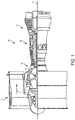
FIG. 1 is a schematic illustration of a gas turbine engine; -
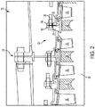
FIG. 2 is a partial section view of a gas turbine engine having a high pressure compressor case; -
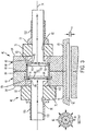
FIG. 3 is a partial section view of an active clearance control system; -
FIG. 4 is a partial section view of an active clearance control system; and -
FIG. 5 is a partial section view of an active clearance control system. - Referring now to the Figures, where the present disclosure will be described with reference to specific embodiments, it is to be understood that the disclosed embodiments are merely illustrative of the present disclosure that may be embodied within various and alternative forms. Various elements of the disclosed embodiments may be combined or omitted to form further embodiments of the present disclosure. The Figures are not necessarily to scale; some features may be exaggerated or minimized to show details of particular components. Therefore, specific structural and functional details disclosed herein are not to be interpreted as limiting, but merely as a representative basis for teaching one skilled in the art to variously employ the present disclosure.
- Referring to
FIG. 1 agas turbine engine 10 is schematically illustrated. Thegas turbine engine 10 may be a two-spool turbofan engine that includes afan section 12, acompressor section 14, acombustor section 16, and aturbine section 18. Alternative gas turbine engines may include an augmenter section (not shown) among other systems or features. Thefan section 12, thecompressor section 14, thecombustor section 16, and theturbine section 18 may be rotatable about a longitudinal axis A. - The
fan section 12 drives air along a bypass flow path B, while thecompressor section 14 drives air along a core flow path C for compression and communication into thecombustor section 16. Hot combustion gases generated within thecombustor section 16 are expanded through theturbine section 18. Although depicted as a turbofan gas turbine engine, it should be understood that the concepts described herein are not limited to turbofan engines and these teachings could extend to other types of engines, including but not limited to, three-spool engine architectures. - Referring to
FIG. 2 , a partial section view of thegas turbine engine 10 is shown. Thegas turbine engine 10 includes acase assembly 20 disposed about thecompressor section 14. Thecase assembly 20 includes a high pressure compressorinner case assembly 22 disposed within a high pressure compressorouter case assembly 24. The high pressure compressorinner case assembly 22 includes a high pressurecompressor rotor assembly 26, a plurality ofrotor blades 28 extending from the high pressurecompressor rotor assembly 26, and a plurality ofvanes 30 extending from a high pressure compressorouter case assembly 24. - The high pressure compressor
inner case assembly 22 further includes a firstinner case 34 coupled to a secondinner case 32 by afastener 36. During operation of thegas turbine engine 10 the high pressure compressorinner case assembly 22 may benefit from control of clearances between components of the high pressure compressorinner case assembly 22 and the high pressurecompressor rotor assembly 26 by providing cooling or heating air to the flanges of the high pressure compressorinner case assembly 22 or the high pressure compressorouter case assembly 24 by an active caseclearance control system 40. The active caseclearance control system 40 uses an external air source that may be a heated or cooled air source to change the temperature gradient within the flanges of the case assemblies to control their thermal expansion response. This is used to match the expansion/contraction (thermo-mechanical response) of the rotor during operation to allow for an active rotor tip clearance control to optimize the efficiency of thegas turbine engine 10. - Referring to
FIG. 3 , a partial sectional view of the active caseclearance control system 40 is shown. The active caseclearance control system 40 includes afirst flange 42 of the firstinner case 34, asecond flange 44 of the secondinner case 32, and aclearance control fastener 46. - The
first flange 42 extends from afirst case body 50 of the firstinner case 34. Thefirst flange 42 is disposed substantially perpendicular to thefirst case body 50 of the firstinner case 34. Thefirst flange 42 defines afirst opening 52 that extends from a first flange first face 54 to a first flangesecond face 56. The first flangefirst face 54 is disposed substantially parallel to the first flangesecond face 56. Thefirst opening 52 includes a first flangeinterior surface 58. The first flangeinterior surface 58 extends about thefirst opening 52. - The
second flange 44 extends from asecond case body 60 of the secondinner case 32. Thesecond flange 44 is disposed substantially perpendicular to thesecond case body 60 of the secondinner case 32. Thesecond flange 44 defines asecond opening 62 that extends from a second flange first face 64 to a second flangesecond face 66. The second flange first face 64 is disposed substantially parallel to the second flangesecond face 66. The second flange first face 64 abuts the first flange first face 54 when the firstinner case 34 is coupled to the secondinner case 32 by theclearance control fastener 46. Thesecond opening 62 includes a second flangeinterior surface 68. The second flangeinterior surface 68 extends about thesecond opening 62. - The
clearance control fastener 46 extends through thefirst opening 52 of thefirst flange 42 of the firstinner case 34 and extends through thesecond opening 62 of thesecond flange 44 of the secondinner case 32. Theclearance control fastener 46 is configured to take low pressure air from an upstream low pressure air source and flow the low pressure air through theclearance control fastener 46 and into an interior region of at least one of thefirst flange 42 of the firstinner case 34 and thesecond flange 44 of the secondinner case 32 and ultimately delivers the low pressure air to a low pressure sink. The low pressure air cools or heats at least one of thefirst flange 42 of the firstinner case 34 and thesecond flange 44 of the secondinner case 32 from the inside out. By using at least one of thefirst opening 52 and thesecond opening 62 minimal reconfiguration of the high pressure compressorinner case assembly 22 is required. - The
clearance control fastener 46 includes afastener head 70, afastener shank 72 extending from thefastener head 70 along afastener axis 74, and acoupling nut 76. Theclearance control fastener 46 further includes afirst bore 80, asecond bore 82, anoutlet port 84, and aninlet port 86. - The
first bore 80 extends through thefastener head 70 and at least partially through thefastener shank 72 along thefastener axis 74. Thefirst bore 80 extends along thefastener axis 74 towards theoutlet port 84. Theoutlet port 84 is defined by thefastener shank 72. Theoutlet port 84 extends along anoutlet port axis 90 that is disposed transverse to thefastener axis 74. Theoutlet port 84 is disposed proximate the first flangeinterior surface 58. Theoutlet port 84 includes afirst opening 92 and thesecond opening 94 radially spaced apart from thefirst opening 92. As shown in Section A-A theoutlet port 84 may contain a plurality of openings. - The
second bore 82 extends from an end of thefastener shank 72 disposed opposite thefastener head 70 towards thefastener head 70 along thefastener axis 74. Thesecond bore 82 extends along thefastener axis 74 towards theinlet port 86. Theinlet port 86 extends along aninlet port axis 100 that is disposed transverse to thefastener axis 74. Theinlet port axis 100 is disposed substantially parallel to theoutlet port axis 90. Theinlet port 86 is disposed proximate the second flangeinterior surface 68. Theinlet port 86 includes athird opening 102 and afourth opening 104 radially spaced apart from thethird opening 102. Similar to the outlet port, theinlet port 86 may contain a plurality of openings. - The
first bore 80 is separated from thesecond bore 82 by abluff body 110 defined by thefastener shank 72. Thefirst opening 92 and thesecond opening 94 of theoutlet port 84 are separated from thethird opening 102 and thefourth opening 104 of theinlet port 86 by thebluff body 110. - The first flange
interior surface 58, the second flangeinterior surface 68, and thefastener shank 72 define acavity 112. Thecavity 112 fluidly connects theoutlet port 84 to theinlet port 86. Theoutlet port 84 provides an inlet into thecavity 112 forlow pressure air 130 received through anentrance component 120 fluidly connected to thefirst bore 80 of thefastener head 70. Theinlet port 86 provides an outlet from thecavity 112 for the low pressure air that cools or heats the interior surfaces of the flanges to anexit component 122 fluidly connected to thesecond bore 82 of thefastener shank 72. Theentrance component 120 andexit component 122 may be fittings, bolts, cavities, instrumentation egress is, pipes, tubing, or the like that are configured to deliver and receive air. - The
low pressure air 130 that cools or heats the interior surfaces of the flanges that exits through theexit component 122 may be provided to a subsequent clearance control fastener downstream of theclearance control fastener 46. In at least one embodiment, the low pressure air that cools or heats the interior surfaces of the flanges that exits through theexit component 122 may be provided to a bleed air pipe, a bleed air manifold, a low pressure turbine, overboard into a nacelle purge, routed through at least one of the firstinner case 34 and the secondinner case 32 to an existing cooling air pipe, or provided to a bearing cooling air system. The active caseclearance control system 40 controls a rotor tip clearance, c, between a rotor blade of the plurality ofrotor blades 28 and at least one of thefirst case body 50 and thesecond case body 60 and anouter air seal 140. This maintains a more consistent clearance, c, between a tip of a rotor blade of the plurality ofrotor blades 28 to reduce rubbing between the tip of the rotor blade of the plurality ofrotor blades 28 and the abradable material disposed on theouter air seal 140. This increases or improves the aerodynamic efficiency of a given stage that incorporates the active caseclearance control system 40. - Referring to
FIG. 4 , a partial sectional view of the second illustrative active caseclearance control system 150 is shown. The active caseclearance control system 150 includes afirst flange 160 of the firstinner case 34, asecond flange 162 of the secondinner case 32, anouter air seal 164, and aclearance control fastener 166. - The
first flange 160 extends from thefirst case body 50 of the firstinner case 34. Thefirst flange 160 defines afirst opening 170 and afirst port 172. Thefirst opening 170 extends from a first flangefirst face 174 to a first flangesecond face 176. Thefirst opening 170 includes a first flangeinterior surface 178 that extends circumferentially about the interior of thefirst opening 170. Thefirst port 172 extends tangentially from the first flangeinterior surface 178 along afirst port axis 180. - The
second flange 162 extends from thesecond case body 60 of the secondinner case 32. Thesecond flange 162 defines asecond opening 190 and asecond port 192. Thesecond opening 190 extends from a second flangefirst face 194 to the second flangesecond face 196. The second flangesecond face 196 of the secondinner case 32 abuts the first flangesecond face 176 of the firstinner case 34 when the firstinner case 34 is coupled to the secondinner case 32 by theclearance control fastener 166. - The
second opening 190 includes a second flangeinterior surface 198 that extends circumferentially about thesecond opening 190. Thesecond port 192 extends tangentially from the second flangeinterior surface 198 along asecond port axis 200. Thesecond port axis 200 is disposed substantially parallel to thefirst port axis 180. - The
clearance control fastener 166 includes afastener head 210, afastener shank 212, and acoupling nut 214. Thefastener shank 212 extends from thefastener head 210 along afastener axis 216. Thefastener shank 212 extends through thefirst opening 170 of thefirst flange 160 and thesecond opening 190 of thesecond flange 162. Theclearance control fastener 166 includes afirst bore 220, asecond bore 222, anoutlet port 224, and aninlet port 226. - The
first bore 220 extends through thefastener head 210 and at least partially through thefastener shank 212 along thefastener axis 216. In at least one embodiment, thefastener head 210 is not provided. In such an embodiment, thefirst bore 220 extends at least partially through thefastener shank 212 along thefastener axis 216. Thefirst bore 220 extends along thefastener axis 216 towards theoutlet port 224. Theoutlet port 224 is defined by thefastener shank 212. Theoutlet port 224 extends along anoutlet port axis 230 that is disposed transverse to thefastener axis 216. Theoutlet port 224 is proximately aligned with thefirst port 172 such that theoutlet port axis 230 is proximately aligned with thefirst port axis 180. - The
second bore 222 extends from an end of thefastener shank 212 disposed opposite thefastener head 210 along thefastener axis 216. Thesecond bore 222 is disposed opposite thefirst bore 220. Thesecond bore 222 extends along thefastener axis 216 towards theinlet port 226. Theinlet port 226 is defined by thefastener shank 212. Theinlet port 226 extends along an inlet port axis 232 that is disposed transverse to thefastener axis 216. The inlet port axis 232 is disposed substantially parallel to theoutlet port axis 230. Theinlet port 226 is proximately aligned with thesecond port 192 such that the inlet port axis 232 is proximately aligned with thesecond port axis 200. - The
first bore 220 is separated from thesecond bore 222 by a portion of the body 234 of thefastener shank 212. Theoutlet port 224 is separated from theinlet port 226 by the portion of the body 234 of thefastener shank 212. - The
first flange 160, thesecond flange 162, and theouter air seal 164 define amanifold 240. The manifold 240 fluidly connects theoutlet port 224 and thefirst port 172 to theinlet port 226 and thesecond port 192. Thefirst port 172 and thesecond port 192 extend towards themanifold 240. - A
distribution gland 242 is disposed within themanifold 240. Thedistribution gland 242 extends from thefirst port 172 towards theouter air seal 164. Thedistribution gland 242 is configured to receivelow pressure air 250 that is supplied to thefirst bore 220 through thefirst port 172 and distributes thelow pressure air 250 within themanifold 240. The distributedlow pressure air 250 within themanifold 240 is configured to cool at least one of thefirst flange 160, thesecond flange 162, and theouter air seal 164. The distributedlow pressure air 250 is configured to exit through thesecond port 192 and through thesecond bore 222. The active caseclearance control system 150 controls a rotor tip clearance, d, between a rotor blade of the plurality ofrotor blades 28 and theouter air seal 164. This maintains a more consistent clearance, d, between a tip of a rotor blade of the plurality ofrotor blades 28 to reduce rubbing between the tip of the rotor blade of the plurality ofrotor blades 28 and an abradable material disposed on theouter air seal 164. This increases or improves the aerodynamic efficiency of a given stage that incorporates the active caseclearance control system 150. - Referring to
FIG. 5 , a partial sectional view of the third illustrative active caseclearance control system 300 is shown. The active caseclearance control system 300 includes afirst flange 302 of a first case, asecond flange 304 of a second case, and aclearance control fastener 306. - The
first flange 302 includes afirst body 310, afirst wall 312, and afirst arm 314. Thefirst wall 312 extends from thefirst body 310. Thefirst wall 312 defines afirst opening 320 that extends from a first wallouter surface 322 to a first wallinner surface 324. The first wallinner surface 324 defines a first plurality offins 326. The first plurality offins 326 extend away from the first wallinner surface 324. - The
first arm 314 extends from an end of thefirst wall 312. Thefirst arm 314 is disposed substantially perpendicular to thefirst wall 312. Thefirst arm 314 is disposed substantially parallel to the first plurality offins 326. Thefirst arm 314 includes a firstarm end face 330. The firstarm end face 330 is disposed substantially parallel to the first wallinner surface 324. The firstarm end face 330 is spaced apart from the first wallinner surface 324. - The
second flange 304 includes asecond body 340, asecond wall 342, and asecond arm 344. Thesecond wall 342 extends from thesecond body 340. Thesecond wall 342 defines asecond opening 350 that extends from a second wallouter surface 352 to a second wallinner surface 354. The second wallinner surface 354 defines a second plurality offins 356. The second plurality offins 356 extend away from the second wallinner surface 354 towards thefirst wall 312. - The
second arm 344 extends from an end of thesecond wall 342. Thesecond arm 344 is disposed substantially perpendicular to thesecond wall 342. Thesecond arm 344 is disposed substantially parallel to the second plurality offins 356. Thesecond arm 344 includes a secondarm end face 360. The secondarm end face 360 is spaced apart from the second wallinner surface 354. - The second
arm end face 360 abuts the firstarm end face 330 and thesecond body 340 abuts thefirst body 310 when thefirst flange 302 of the first case is coupled to thesecond flange 304 of the second case by theclearance control fastener 306. Theclearance control fastener 306 extends through thefirst opening 320 of thefirst flange 302 and thesecond opening 350 of thesecond flange 304. - The
clearance control fastener 306 includes afastener head 370, afastener shank 372, and acoupling nut 374. Thefastener shank 372 extends from thefastener head 370 along afastener axis 376. Thefastener shank 372 extends through thefirst opening 320 to thefirst flange 302 and thesecond opening 350 of thesecond flange 304. - The
clearance control fastener 306 includes afirst bore 380, asecond bore 382, anoutlet port 384, and aninlet port 386. Thefirst bore 380 extends through thefastener head 370 and at least partially through thefastener shank 372 along thefastener axis 376. Thefirst bore 380 extends along thefastener axis 376 towards theoutlet port 384. Theoutlet port 384 is defined by thefastener shank 372. Theoutlet port 384 extends along anoutlet port axis 390 that is disposed transverse to thefastener axis 376. Theoutlet port 384 includes a first opening 392 and the second opening 394 radially spaced apart from the first opening 392. In at least one embodiment, additional openings may be provided. - The
second bore 382 extends from an end of thefastener shank 372 disposed opposite thefastener head 370 towards thefastener head 370 along thefastener axis 376. Thesecond bore 382 extends along thefastener axis 376 towards theinlet port 386. Theinlet port 386 extends along aninlet port axis 400 that is disposed transverse to thefastener axis 376. Theinlet port axis 400 is disposed substantially parallel to theoutlet port axis 390. Theinlet port 386 includes a third opening 402 and afourth opening 404 radially spaced apart from the third opening 402. In at least one embodiment, additional openings may be provided. - The
first bore 380 is separated from thesecond bore 382 by abody 410 defined by thefastener shank 372. The first opening 392 and the second opening 394 of theoutlet port 384 are separated from the third opening 402 and thefourth opening 404 of theinlet port 86 by thebody 410. - The
first body 310, thefirst wall 312, and thefirst arm 314 of thefirst flange 302 and thesecond body 340, thesecond wall 342, and thesecond arm 344 of thesecond flange 304 define acavity 420. Thecavity 420 fluidly connects theoutlet port 384 to theinlet port 386. Theoutlet port 384 provides an inlet into thecavity 420 forlow pressure air 430 received through thefirst bore 380 of theclearance control fastener 306. Theinlet port 386 receives thelow pressure air 430 that cools or heats the inner wall surfaces of the flanges and provides that air to thesecond bore 382 of theclearance control fastener 306. - The
low pressure air 430 that enters into thecavity 420 may have an enhanced cooling effect due to at least one of the first plurality offins 326 and the second plurality offins 356. At least one of the first plurality offins 326 and the second plurality offins 356 increases the heat transfer rate and thus enhances the cooling effect of thelow pressure air 430. The first plurality offins 326 and the second plurality offins 356 may have geometric shapes such as grooves, ridges, trip strips, protrusions, projections, or the like that increase contact area and the heat transfer rate. The active caseclearance control system 300 controls a rotor tip clearance, e, between a rotor blade of the plurality ofrotor blades 28 and thefirst body 310 and anouter air seal 440. This maintains a more consistent clearance, e, between a tip of a rotor blade of the plurality ofrotor blades 28 to reduce rubbing between the tip of the rotor blade of the plurality ofrotor blades 28 and an abradable material disposed on theouter air seal 440. This increases or improves the aerodynamic efficiency of a given stage that incorporates the active caseclearance control system 300. - The active clearance control systems provide direct flange cooling or heating that allows for active control of the high pressure compressor component clearances. In at least one embodiment, the active clearance control systems provide approximately 0.005 inches (0.013 cm) of close down at steady-state gas turbine engine operating points. This allows for more open clearances on bowed rotor starts, or other rub points in the mission, as well as increasing the gas turbine engine efficiency at steady-state operating points. The active clearance control systems may also be used to speed up the flange responses during deceleration to better match the transient rotor response of the high pressure compressor.
- Throughout this specification, the term "attach," "attachment," "connected", "coupled," "coupling," "mount," or "mounting" shall be interpreted to mean that a structural component or element is in some manner connected to or contacts another element, either directly or indirectly through at least one intervening structural element, or is integrally formed with the other structural element.
- While the present disclosure has been described in detail in connection with only a limited number of embodiments, it should be readily understood that the present disclosure is not limited to such disclosed embodiments. Rather, the present disclosure can be modified to incorporate any number of variations, alterations, substitutions or equivalent arrangements not heretofore described, but which are commensurate with the scope of the present disclosure. Additionally, while various embodiments of the present disclosure have been described, it is to be understood that aspects of the present disclosure may include only some of the described embodiments. Accordingly, the present disclosure is not to be seen as limited by the foregoing description, but is only limited by the scope of the appended claims.
- The following clauses set out aspects of the present disclosure which may or may not be claimed but which may form basis for future amendments and/or a divisional application.
- 1. A gas turbine engine, comprising:
- a first case having a first flange defining a first opening;
- a second case having a second flange defining a second opening, the second flange abuts the first flange; and
- a fastener extending through the first opening and the second opening, the fastener defining a first bore extending through a fastener head along an axis towards an outlet port defined by a fastener shank.
- 2. The gas turbine engine of clause 1, wherein the fastener defines a second bore extending along the axis towards the fastener head.
- 3. The gas turbine engine of clause 2, wherein the second bore is separated from the first bore by a bluff body defined by the fastener shank.
- 4. The gas turbine engine of clause 2, wherein the second bore extends towards an inlet port defined by the fastener shank.
- 5. The gas turbine engine of clause 4, wherein the outlet port is disposed proximate a first flange interior surface defined by the first opening.
- 6. The gas turbine engine of clause 5, wherein the inlet port is disposed proximate a second flange interior surface defined by the second opening.
- 7. The gas turbine engine of clause 6, wherein the first flange interior surface, the second flange interior surface and the fastener shank define a cavity that fluidly connects the outlet port and the inlet port.
- 8. The gas turbine engine of clause 7, wherein the cavity receives low pressure air that is supplied through the outlet port to at least one of cool and heat the first flange interior surface and the second flange interior surface.
- 9. A gas turbine engine, comprising:
- a first case having a first flange defining a first opening and a first port extending from a first flange interior surface;
- a second case having a second flange defining a second opening and a second port extending from a second flange interior surface; and
- a fastener having a fastener shank extending through the first opening and the second opening, the fastener shank defining a first bore extending along an axis towards an outlet port defined by the fastener shank, the outlet port proximately aligned with the first port.
- 10. The gas turbine engine of clause 9, wherein the fastener shank defines a second bore extending along the axis towards an inlet port defined by the fastener shank, the inlet port proximately aligned with the second port.
- 11. The gas turbine engine of
clause 10, wherein the first port and the second port extend towards a manifold defined by the first flange, the second flange, and an outer air seal. - 12. The gas turbine engine of clause 11, further comprising a distribution gland disposed within the manifold, the distribution gland extending from the first port towards the outer air seal.
- 13. The gas turbine engine of
clause 12, wherein the distribution gland is configured to receive low pressure air that is supplied to the first bore and distributes the low pressure air within the manifold. - 14. A case clearance control system for a gas turbine engine, comprising:
- a fastener extending through a first opening of a first flange and a second opening of a second flange to couple the first flange to the second flange, the fastener having:
- a fastener head, and
- a fastener shank extending from the fastener head along an axis, the fastener shank defining an outlet port extending transverse to the axis and an inlet port spaced apart from the outlet port, the inlet port extending transverse to the axis.
- a fastener extending through a first opening of a first flange and a second opening of a second flange to couple the first flange to the second flange, the fastener having:
- 15. The case clearance control system of
clause 14, wherein the fastener head and the fastener shank define a first bore that extends along the axis from the fastener head to the outlet port. - 16. The case clearance control system of clause 15, wherein the fastener shank defines a second bore that extends along the axis from an end of the fastener shank to the inlet port.
- 17. The case clearance control system of
clause 16, wherein the first flange has a first body, a first wall extending from the first body, the first wall defining a first opening, and a first arm extending from the first wall and the second flange has a second body, a second wall extending from the second body, the second wall defining a second opening, and a second arm extending away from the second wall and extending towards the first arm, the first wall, the first arm, the second body, the second wall, and the second arm define a cavity. - 18. The case clearance control system of clause 17, wherein an inner surface of the first wall defines a plurality of fins that extend towards the second wall.
- 19. The case clearance control system of clause 17, wherein an inner surface of the second wall defines a plurality of fins that extend towards the first wall.
- 20. The case clearance control system of clause 17, wherein the outlet port receives low pressure air to at least one of cool and heat an inner surface of the first wall and the second wall.
Claims (15)
- A case clearance control system (40; 150; 300) for a gas turbine engine (10), comprising:a fastener (46; 166; 306) configured to extend through a first opening (52; 170; 320) of a first flange (42; 160; 302) and a second opening (62; 140; 350) of a second flange (42; 162; 304) to couple the first flange to the second flange, the fastener having:a fastener head (70; 210; 370), anda fastener shank (72; 212; 372) extending from the fastener head along an axis (74; 216; 376), the fastener shank defining an outlet port (84; 224; 384) extending transverse to the axis and an inlet port (86; 226; 386) spaced apart from the outlet port, the inlet port extending transverse to the axis.
- A gas turbine engine (10), comprising:a first case (34) having a first flange (42; 160; 302) defining a first opening (52; 170; 320);a second case (32) having a second flange (44; 162; 304) defining a second opening (62; 190; 350), the second flange abuts the first flange; andthe case clearance control system of claim 1.
- The gas turbine engine (10) of claim 2, wherein the fastener (46; 166; 306) defines a second bore (82; 222; 382) extending along the axis (74; 216; 376) towards the fastener head (70; 210; 370), preferably
wherein the second bore (82) is separated from the first bore (80) by a bluff body (110) defined by the fastener shank (72). - The gas turbine engine (10) of claim 3, wherein the second bore (82; 222; 382) extends towards the inlet port (86; 226; 386) defined by the fastener shank (72; 212; 372).
- The gas turbine engine (10) of any of claims 2 to 4, wherein the outlet port (84; 224) is disposed proximate a first flange interior surface (58; 178) defined by the first opening (52; 170), and/or
wherein the inlet port (86; 226) is disposed proximate a second flange interior surface (68; 198) defined by the second opening (62; 190). - The gas turbine engine (10) of claim 5, wherein the first flange interior surface (58), the second flange interior surface (68) and the fastener shank (72) define a cavity (112) that fluidly connects the outlet port (84) and the inlet port (82).
- The gas turbine engine (10) of claim 6, wherein the cavity (112) receives low pressure air (130) that is supplied through the outlet port (84) to at least one of cool and heat the first flange interior surface (58) and the second flange interior surface (68).
- A gas turbine engine (10), comprising:a first case (34) having a first flange (160) defining a first opening (170) and a first port (172) extending from a first flange interior surface (178);a second case (32) having a second flange (162) defining a second opening (190) and a second port (192) extending from a second flange interior surface (198); anda fastener (166) having a fastener shank (212) extending through the first opening and the second opening, the fastener shank defining a first bore (220) extending along an axis (216) towards an outlet port (224) defined by the fastener shank, the outlet port is proximately aligned with the first port.
- The gas turbine engine (10) of claim 8, wherein the fastener shank (212) defines a second bore (222) extending along the axis (216) towards an inlet port (226) defined by the fastener shank, the inlet port is proximately aligned with the second port (192).
- The gas turbine engine (10) of claim 8 or 9, wherein the first port (172) and the second port (192) extend towards a manifold (240) defined by the first flange (160), the second flange (162), and an outer air seal (164).
- The gas turbine engine (10) of claim 10, further comprising a distribution gland (242) disposed within the manifold (240), the distribution gland extending from the first port (172) towards the outer air seal (164), preferably
wherein the distribution gland is configured to receive low pressure air (250) that is supplied to the first bore (220) and distributes the low pressure air within the manifold. - The case clearance control system (40; 150; 300) of claim 1, wherein the fastener head (70; 210; 370) and the fastener shank (72; 212; 372) define a first bore (80; 220; 380) that extends along the axis (74; 216; 376) from the fastener head to the outlet port (84; 224; 384), preferably
wherein the fastener shank defines a second bore (82; 222; 382) that extends along the axis from an end of the fastener shank to the inlet port. - The case clearance control system (300) of claim 1 or 12, wherein the first flange (302) has a first body (310), a first wall (312) extending from the first body, the first wall defining a first opening (320), and a first arm (314) extending from the first wall and the second flange (304) has a second body (340), a second wall (342) extending from the second body, the second wall defining a second opening (350), and a second arm (344) extending away from the second wall and extending towards the first arm, the first wall, the first arm, the second body, the second wall, and the second arm define a cavity (420).
- The case clearance control system (300) of claim 13, wherein an inner surface (324) of the first wall (312) defines a plurality of fins (326) that extend towards the second wall (342), and/or
wherein an inner surface (354) of the second wall defines a plurality of fins (356) that extend towards the first wall. - The case clearance control system (300) of claim 13 or 14, wherein the outlet port (384) receives low pressure air (430) to at least one of cool and heat an inner surface (324; 354) of the first wall (312) and the second wall (342).
Applications Claiming Priority (1)
| Application Number | Priority Date | Filing Date | Title |
|---|---|---|---|
| US15/137,193 US10801354B2 (en) | 2016-04-25 | 2016-04-25 | Gas turbine engine having high pressure compressor case active clearance control system |
Publications (2)
| Publication Number | Publication Date |
|---|---|
| EP3239476A1 true EP3239476A1 (en) | 2017-11-01 |
| EP3239476B1 EP3239476B1 (en) | 2019-06-05 |
Family
ID=58632835
Family Applications (1)
| Application Number | Title | Priority Date | Filing Date |
|---|---|---|---|
| EP17168032.5A Active EP3239476B1 (en) | 2016-04-25 | 2017-04-25 | Case clearance control system and corresponding gas turbine engine |
Country Status (2)
| Country | Link |
|---|---|
| US (1) | US10801354B2 (en) |
| EP (1) | EP3239476B1 (en) |
Families Citing this family (5)
| Publication number | Priority date | Publication date | Assignee | Title |
|---|---|---|---|---|
| US10458429B2 (en) | 2016-05-26 | 2019-10-29 | Rolls-Royce Corporation | Impeller shroud with slidable coupling for clearance control in a centrifugal compressor |
| US10989062B2 (en) | 2019-04-18 | 2021-04-27 | Rolls-Royce North American Technologies Inc. | Blade tip clearance assembly with geared cam |
| US11008882B2 (en) | 2019-04-18 | 2021-05-18 | Rolls-Royce North American Technologies Inc. | Blade tip clearance assembly |
| US12345162B2 (en) | 2023-11-17 | 2025-07-01 | Rolls-Royce Corporation | Adjustable position impeller shroud for centrifugal compressors |
| US12345163B2 (en) | 2023-11-17 | 2025-07-01 | Rolls-Royce Corporation | Travel stop for a tip clearance control system |
Citations (5)
| Publication number | Priority date | Publication date | Assignee | Title |
|---|---|---|---|---|
| US3864056A (en) * | 1973-07-27 | 1975-02-04 | Westinghouse Electric Corp | Cooled turbine blade ring assembly |
| US20040219009A1 (en) * | 2003-03-06 | 2004-11-04 | Snecma Moteurs | Turbomachine with cooled ring segments |
| EP2770168A2 (en) * | 2013-02-25 | 2014-08-27 | Pratt & Whitney Canada Corp. | Gas turbine engine with an active tip clearance control |
| WO2015023321A2 (en) * | 2013-04-18 | 2015-02-19 | United Technologies Corporation | Radial position control of case supported structure with axial reaction member |
| EP3115565A1 (en) * | 2015-06-29 | 2017-01-11 | Rolls-Royce Corporation | Turbine shroud segment with load distribution springs |
Family Cites Families (4)
| Publication number | Priority date | Publication date | Assignee | Title |
|---|---|---|---|---|
| GB2047354B (en) * | 1979-04-26 | 1983-03-30 | Rolls Royce | Gas turbine engines |
| US8550778B2 (en) * | 2010-04-20 | 2013-10-08 | Mitsubishi Heavy Industries, Ltd. | Cooling system of ring segment and gas turbine |
| GB201213039D0 (en) * | 2012-07-23 | 2012-09-05 | Rolls Royce Plc | Fastener |
| US10132194B2 (en) * | 2015-12-16 | 2018-11-20 | Rolls-Royce North American Technologies Inc. | Seal segment low pressure cooling protection system |
-
2016
- 2016-04-25 US US15/137,193 patent/US10801354B2/en active Active
-
2017
- 2017-04-25 EP EP17168032.5A patent/EP3239476B1/en active Active
Patent Citations (5)
| Publication number | Priority date | Publication date | Assignee | Title |
|---|---|---|---|---|
| US3864056A (en) * | 1973-07-27 | 1975-02-04 | Westinghouse Electric Corp | Cooled turbine blade ring assembly |
| US20040219009A1 (en) * | 2003-03-06 | 2004-11-04 | Snecma Moteurs | Turbomachine with cooled ring segments |
| EP2770168A2 (en) * | 2013-02-25 | 2014-08-27 | Pratt & Whitney Canada Corp. | Gas turbine engine with an active tip clearance control |
| WO2015023321A2 (en) * | 2013-04-18 | 2015-02-19 | United Technologies Corporation | Radial position control of case supported structure with axial reaction member |
| EP3115565A1 (en) * | 2015-06-29 | 2017-01-11 | Rolls-Royce Corporation | Turbine shroud segment with load distribution springs |
Also Published As
| Publication number | Publication date |
|---|---|
| US20170306785A1 (en) | 2017-10-26 |
| US10801354B2 (en) | 2020-10-13 |
| EP3239476B1 (en) | 2019-06-05 |
Similar Documents
| Publication | Publication Date | Title |
|---|---|---|
| EP3239476B1 (en) | Case clearance control system and corresponding gas turbine engine | |
| US9506369B2 (en) | Tip clearance control for turbine blades | |
| US6990797B2 (en) | Methods and apparatus for operating gas turbine engines | |
| CA2567938C (en) | Methods and apparatuses for cooling gas turbine engine rotor assemblies | |
| US7708518B2 (en) | Turbine blade tip clearance control | |
| JP5383973B2 (en) | System and method for exhausting used cooling air for gas turbine engine active clearance control | |
| US20050023412A1 (en) | Nacelle inlet lip anti-icing with engine oil | |
| EP3040519B1 (en) | Tip clearance control for turbine blades | |
| CN106014493A (en) | Systems for Cooling Turbine Engines | |
| JP2008031997A (en) | Heat transfer system for turbine engine using heat pipe | |
| US9982543B2 (en) | Partial cavity baffles for airfoils in gas turbine engines | |
| EP3040518A1 (en) | Tip clearance control for turbine blades | |
| CN104956035B (en) | Active clearance control system based on aspirator | |
| CN106917683B (en) | Gas-turbine unit and cooling system for it | |
| US10815884B2 (en) | Gas turbine engine de-icing system | |
| JP2017110652A (en) | Active high pressure compressor clearance control | |
| BR102015002096A2 (en) | hot gas path component | |
| EP3153682A1 (en) | Turbine engine assembly and method of operating thereof | |
| JP2017025910A (en) | Cooling structure for fixed blades | |
| US8333549B2 (en) | Air cycle machine turbine outlet heated diffuser | |
| US11970946B2 (en) | Clearance control assembly | |
| CN117836508A (en) | System for cooling refrigerant of an aircraft and comprising a safety heating device and method of using such a system | |
| RU2506435C2 (en) | Gas turbine engine and method for radial clearance adjustment in gas turbine | |
| EP3070265B1 (en) | Vane | |
| CN108026780B (en) | Ventilation device for turbine casing |
Legal Events
| Date | Code | Title | Description |
|---|---|---|---|
| PUAI | Public reference made under article 153(3) epc to a published international application that has entered the european phase |
Free format text: ORIGINAL CODE: 0009012 |
|
| STAA | Information on the status of an ep patent application or granted ep patent |
Free format text: STATUS: THE APPLICATION HAS BEEN PUBLISHED |
|
| AK | Designated contracting states |
Kind code of ref document: A1 Designated state(s): AL AT BE BG CH CY CZ DE DK EE ES FI FR GB GR HR HU IE IS IT LI LT LU LV MC MK MT NL NO PL PT RO RS SE SI SK SM TR |
|
| AX | Request for extension of the european patent |
Extension state: BA ME |
|
| STAA | Information on the status of an ep patent application or granted ep patent |
Free format text: STATUS: REQUEST FOR EXAMINATION WAS MADE |
|
| 17P | Request for examination filed |
Effective date: 20180501 |
|
| RBV | Designated contracting states (corrected) |
Designated state(s): AL AT BE BG CH CY CZ DE DK EE ES FI FR GB GR HR HU IE IS IT LI LT LU LV MC MK MT NL NO PL PT RO RS SE SI SK SM TR |
|
| GRAP | Despatch of communication of intention to grant a patent |
Free format text: ORIGINAL CODE: EPIDOSNIGR1 |
|
| STAA | Information on the status of an ep patent application or granted ep patent |
Free format text: STATUS: GRANT OF PATENT IS INTENDED |
|
| INTG | Intention to grant announced |
Effective date: 20181119 |
|
| GRAS | Grant fee paid |
Free format text: ORIGINAL CODE: EPIDOSNIGR3 |
|
| GRAA | (expected) grant |
Free format text: ORIGINAL CODE: 0009210 |
|
| STAA | Information on the status of an ep patent application or granted ep patent |
Free format text: STATUS: THE PATENT HAS BEEN GRANTED |
|
| AK | Designated contracting states |
Kind code of ref document: B1 Designated state(s): AL AT BE BG CH CY CZ DE DK EE ES FI FR GB GR HR HU IE IS IT LI LT LU LV MC MK MT NL NO PL PT RO RS SE SI SK SM TR |
|
| REG | Reference to a national code |
Ref country code: GB Ref legal event code: FG4D |
|
| REG | Reference to a national code |
Ref country code: CH Ref legal event code: EP |
|
| REG | Reference to a national code |
Ref country code: AT Ref legal event code: REF Ref document number: 1140181 Country of ref document: AT Kind code of ref document: T Effective date: 20190615 |
|
| REG | Reference to a national code |
Ref country code: IE Ref legal event code: FG4D |
|
| REG | Reference to a national code |
Ref country code: DE Ref legal event code: R096 Ref document number: 602017004273 Country of ref document: DE |
|
| REG | Reference to a national code |
Ref country code: NL Ref legal event code: MP Effective date: 20190605 |
|
| REG | Reference to a national code |
Ref country code: LT Ref legal event code: MG4D |
|
| PG25 | Lapsed in a contracting state [announced via postgrant information from national office to epo] |
Ref country code: ES Free format text: LAPSE BECAUSE OF FAILURE TO SUBMIT A TRANSLATION OF THE DESCRIPTION OR TO PAY THE FEE WITHIN THE PRESCRIBED TIME-LIMIT Effective date: 20190605 Ref country code: LT Free format text: LAPSE BECAUSE OF FAILURE TO SUBMIT A TRANSLATION OF THE DESCRIPTION OR TO PAY THE FEE WITHIN THE PRESCRIBED TIME-LIMIT Effective date: 20190605 Ref country code: HR Free format text: LAPSE BECAUSE OF FAILURE TO SUBMIT A TRANSLATION OF THE DESCRIPTION OR TO PAY THE FEE WITHIN THE PRESCRIBED TIME-LIMIT Effective date: 20190605 Ref country code: NO Free format text: LAPSE BECAUSE OF FAILURE TO SUBMIT A TRANSLATION OF THE DESCRIPTION OR TO PAY THE FEE WITHIN THE PRESCRIBED TIME-LIMIT Effective date: 20190905 Ref country code: AL Free format text: LAPSE BECAUSE OF FAILURE TO SUBMIT A TRANSLATION OF THE DESCRIPTION OR TO PAY THE FEE WITHIN THE PRESCRIBED TIME-LIMIT Effective date: 20190605 Ref country code: SE Free format text: LAPSE BECAUSE OF FAILURE TO SUBMIT A TRANSLATION OF THE DESCRIPTION OR TO PAY THE FEE WITHIN THE PRESCRIBED TIME-LIMIT Effective date: 20190605 Ref country code: FI Free format text: LAPSE BECAUSE OF FAILURE TO SUBMIT A TRANSLATION OF THE DESCRIPTION OR TO PAY THE FEE WITHIN THE PRESCRIBED TIME-LIMIT Effective date: 20190605 |
|
| PG25 | Lapsed in a contracting state [announced via postgrant information from national office to epo] |
Ref country code: LV Free format text: LAPSE BECAUSE OF FAILURE TO SUBMIT A TRANSLATION OF THE DESCRIPTION OR TO PAY THE FEE WITHIN THE PRESCRIBED TIME-LIMIT Effective date: 20190605 Ref country code: RS Free format text: LAPSE BECAUSE OF FAILURE TO SUBMIT A TRANSLATION OF THE DESCRIPTION OR TO PAY THE FEE WITHIN THE PRESCRIBED TIME-LIMIT Effective date: 20190605 Ref country code: GR Free format text: LAPSE BECAUSE OF FAILURE TO SUBMIT A TRANSLATION OF THE DESCRIPTION OR TO PAY THE FEE WITHIN THE PRESCRIBED TIME-LIMIT Effective date: 20190906 Ref country code: BG Free format text: LAPSE BECAUSE OF FAILURE TO SUBMIT A TRANSLATION OF THE DESCRIPTION OR TO PAY THE FEE WITHIN THE PRESCRIBED TIME-LIMIT Effective date: 20190905 |
|
| REG | Reference to a national code |
Ref country code: AT Ref legal event code: MK05 Ref document number: 1140181 Country of ref document: AT Kind code of ref document: T Effective date: 20190605 |
|
| PG25 | Lapsed in a contracting state [announced via postgrant information from national office to epo] |
Ref country code: CZ Free format text: LAPSE BECAUSE OF FAILURE TO SUBMIT A TRANSLATION OF THE DESCRIPTION OR TO PAY THE FEE WITHIN THE PRESCRIBED TIME-LIMIT Effective date: 20190605 Ref country code: RO Free format text: LAPSE BECAUSE OF FAILURE TO SUBMIT A TRANSLATION OF THE DESCRIPTION OR TO PAY THE FEE WITHIN THE PRESCRIBED TIME-LIMIT Effective date: 20190605 Ref country code: SK Free format text: LAPSE BECAUSE OF FAILURE TO SUBMIT A TRANSLATION OF THE DESCRIPTION OR TO PAY THE FEE WITHIN THE PRESCRIBED TIME-LIMIT Effective date: 20190605 Ref country code: PT Free format text: LAPSE BECAUSE OF FAILURE TO SUBMIT A TRANSLATION OF THE DESCRIPTION OR TO PAY THE FEE WITHIN THE PRESCRIBED TIME-LIMIT Effective date: 20191007 Ref country code: EE Free format text: LAPSE BECAUSE OF FAILURE TO SUBMIT A TRANSLATION OF THE DESCRIPTION OR TO PAY THE FEE WITHIN THE PRESCRIBED TIME-LIMIT Effective date: 20190605 Ref country code: NL Free format text: LAPSE BECAUSE OF FAILURE TO SUBMIT A TRANSLATION OF THE DESCRIPTION OR TO PAY THE FEE WITHIN THE PRESCRIBED TIME-LIMIT Effective date: 20190605 Ref country code: AT Free format text: LAPSE BECAUSE OF FAILURE TO SUBMIT A TRANSLATION OF THE DESCRIPTION OR TO PAY THE FEE WITHIN THE PRESCRIBED TIME-LIMIT Effective date: 20190605 |
|
| PG25 | Lapsed in a contracting state [announced via postgrant information from national office to epo] |
Ref country code: IS Free format text: LAPSE BECAUSE OF FAILURE TO SUBMIT A TRANSLATION OF THE DESCRIPTION OR TO PAY THE FEE WITHIN THE PRESCRIBED TIME-LIMIT Effective date: 20191005 Ref country code: SM Free format text: LAPSE BECAUSE OF FAILURE TO SUBMIT A TRANSLATION OF THE DESCRIPTION OR TO PAY THE FEE WITHIN THE PRESCRIBED TIME-LIMIT Effective date: 20190605 Ref country code: IT Free format text: LAPSE BECAUSE OF FAILURE TO SUBMIT A TRANSLATION OF THE DESCRIPTION OR TO PAY THE FEE WITHIN THE PRESCRIBED TIME-LIMIT Effective date: 20190605 |
|
| REG | Reference to a national code |
Ref country code: DE Ref legal event code: R097 Ref document number: 602017004273 Country of ref document: DE |
|
| PG25 | Lapsed in a contracting state [announced via postgrant information from national office to epo] |
Ref country code: TR Free format text: LAPSE BECAUSE OF FAILURE TO SUBMIT A TRANSLATION OF THE DESCRIPTION OR TO PAY THE FEE WITHIN THE PRESCRIBED TIME-LIMIT Effective date: 20190605 |
|
| PLBE | No opposition filed within time limit |
Free format text: ORIGINAL CODE: 0009261 |
|
| STAA | Information on the status of an ep patent application or granted ep patent |
Free format text: STATUS: NO OPPOSITION FILED WITHIN TIME LIMIT |
|
| PG25 | Lapsed in a contracting state [announced via postgrant information from national office to epo] |
Ref country code: DK Free format text: LAPSE BECAUSE OF FAILURE TO SUBMIT A TRANSLATION OF THE DESCRIPTION OR TO PAY THE FEE WITHIN THE PRESCRIBED TIME-LIMIT Effective date: 20190605 Ref country code: PL Free format text: LAPSE BECAUSE OF FAILURE TO SUBMIT A TRANSLATION OF THE DESCRIPTION OR TO PAY THE FEE WITHIN THE PRESCRIBED TIME-LIMIT Effective date: 20190605 |
|
| 26N | No opposition filed |
Effective date: 20200306 |
|
| PG25 | Lapsed in a contracting state [announced via postgrant information from national office to epo] |
Ref country code: SI Free format text: LAPSE BECAUSE OF FAILURE TO SUBMIT A TRANSLATION OF THE DESCRIPTION OR TO PAY THE FEE WITHIN THE PRESCRIBED TIME-LIMIT Effective date: 20190605 |
|
| PG25 | Lapsed in a contracting state [announced via postgrant information from national office to epo] |
Ref country code: MC Free format text: LAPSE BECAUSE OF FAILURE TO SUBMIT A TRANSLATION OF THE DESCRIPTION OR TO PAY THE FEE WITHIN THE PRESCRIBED TIME-LIMIT Effective date: 20190605 |
|
| REG | Reference to a national code |
Ref country code: CH Ref legal event code: PL |
|
| PG25 | Lapsed in a contracting state [announced via postgrant information from national office to epo] |
Ref country code: LI Free format text: LAPSE BECAUSE OF NON-PAYMENT OF DUE FEES Effective date: 20200430 Ref country code: CH Free format text: LAPSE BECAUSE OF NON-PAYMENT OF DUE FEES Effective date: 20200430 Ref country code: LU Free format text: LAPSE BECAUSE OF NON-PAYMENT OF DUE FEES Effective date: 20200425 |
|
| REG | Reference to a national code |
Ref country code: BE Ref legal event code: MM Effective date: 20200430 |
|
| PG25 | Lapsed in a contracting state [announced via postgrant information from national office to epo] |
Ref country code: BE Free format text: LAPSE BECAUSE OF NON-PAYMENT OF DUE FEES Effective date: 20200430 |
|
| PG25 | Lapsed in a contracting state [announced via postgrant information from national office to epo] |
Ref country code: IE Free format text: LAPSE BECAUSE OF NON-PAYMENT OF DUE FEES Effective date: 20200425 |
|
| PG25 | Lapsed in a contracting state [announced via postgrant information from national office to epo] |
Ref country code: MT Free format text: LAPSE BECAUSE OF FAILURE TO SUBMIT A TRANSLATION OF THE DESCRIPTION OR TO PAY THE FEE WITHIN THE PRESCRIBED TIME-LIMIT Effective date: 20190605 Ref country code: CY Free format text: LAPSE BECAUSE OF FAILURE TO SUBMIT A TRANSLATION OF THE DESCRIPTION OR TO PAY THE FEE WITHIN THE PRESCRIBED TIME-LIMIT Effective date: 20190605 |
|
| PG25 | Lapsed in a contracting state [announced via postgrant information from national office to epo] |
Ref country code: MK Free format text: LAPSE BECAUSE OF FAILURE TO SUBMIT A TRANSLATION OF THE DESCRIPTION OR TO PAY THE FEE WITHIN THE PRESCRIBED TIME-LIMIT Effective date: 20190605 |
|
| REG | Reference to a national code |
Ref country code: DE Ref legal event code: R081 Ref document number: 602017004273 Country of ref document: DE Owner name: RAYTHEON TECHNOLOGIES CORPORATION (N.D.GES.D.S, US Free format text: FORMER OWNER: UNITED TECHNOLOGIES CORPORATION, FARMINGTON, CONN., US Ref country code: DE Ref legal event code: R081 Ref document number: 602017004273 Country of ref document: DE Owner name: RTX CORPORATION (N.D.GES.D. STAATES DELAWARE),, US Free format text: FORMER OWNER: UNITED TECHNOLOGIES CORPORATION, FARMINGTON, CONN., US |
|
| P01 | Opt-out of the competence of the unified patent court (upc) registered |
Effective date: 20230520 |
|
| PGFP | Annual fee paid to national office [announced via postgrant information from national office to epo] |
Ref country code: DE Payment date: 20250319 Year of fee payment: 9 |
|
| REG | Reference to a national code |
Ref country code: DE Ref legal event code: R081 Ref document number: 602017004273 Country of ref document: DE Owner name: RTX CORPORATION (N.D.GES.D. STAATES DELAWARE),, US Free format text: FORMER OWNER: RAYTHEON TECHNOLOGIES CORPORATION (N.D.GES.D.STAATES DELAWARE), ARLINGTON, VA, US |
|
| PGFP | Annual fee paid to national office [announced via postgrant information from national office to epo] |
Ref country code: GB Payment date: 20260319 Year of fee payment: 10 |
|
| PGFP | Annual fee paid to national office [announced via postgrant information from national office to epo] |
Ref country code: FR Payment date: 20260320 Year of fee payment: 10 |