EP3239385A1 - Washing machine - Google Patents
Washing machine Download PDFInfo
- Publication number
- EP3239385A1 EP3239385A1 EP15871908.8A EP15871908A EP3239385A1 EP 3239385 A1 EP3239385 A1 EP 3239385A1 EP 15871908 A EP15871908 A EP 15871908A EP 3239385 A1 EP3239385 A1 EP 3239385A1
- Authority
- EP
- European Patent Office
- Prior art keywords
- drum
- washing machine
- dewatering
- cleaning unit
- drum cleaning
- Prior art date
- Legal status (The legal status is an assumption and is not a legal conclusion. Google has not performed a legal analysis and makes no representation as to the accuracy of the status listed.)
- Withdrawn
Links
- 238000005406 washing Methods 0.000 title claims abstract description 113
- 238000004140 cleaning Methods 0.000 claims abstract description 141
- XLYOFNOQVPJJNP-UHFFFAOYSA-N water Substances O XLYOFNOQVPJJNP-UHFFFAOYSA-N 0.000 claims description 66
- 238000002347 injection Methods 0.000 claims description 11
- 239000007924 injection Substances 0.000 claims description 11
- 230000000694 effects Effects 0.000 abstract description 6
- 238000000034 method Methods 0.000 description 14
- 230000008569 process Effects 0.000 description 12
- 238000010586 diagram Methods 0.000 description 6
- 229920000139 polyethylene terephthalate Polymers 0.000 description 6
- 239000005020 polyethylene terephthalate Substances 0.000 description 6
- 235000014676 Phragmites communis Nutrition 0.000 description 5
- 238000006073 displacement reaction Methods 0.000 description 4
- 229920000515 polycarbonate Polymers 0.000 description 3
- 239000004417 polycarbonate Substances 0.000 description 3
- 239000011112 polyethylene naphthalate Substances 0.000 description 3
- -1 polyethylene terephthalate Polymers 0.000 description 3
- 239000003755 preservative agent Substances 0.000 description 3
- 230000002335 preservative effect Effects 0.000 description 3
- 239000000243 solution Substances 0.000 description 3
- 102100022907 Acrosin-binding protein Human genes 0.000 description 2
- 102100031798 Protein eva-1 homolog A Human genes 0.000 description 2
- 230000009471 action Effects 0.000 description 2
- 239000003599 detergent Substances 0.000 description 2
- 230000006870 function Effects 0.000 description 2
- 238000012423 maintenance Methods 0.000 description 2
- 238000010297 mechanical methods and process Methods 0.000 description 2
- 238000012986 modification Methods 0.000 description 2
- 230000004048 modification Effects 0.000 description 2
- 238000003756 stirring Methods 0.000 description 2
- 239000000126 substance Substances 0.000 description 2
- 101100365087 Arabidopsis thaliana SCRA gene Proteins 0.000 description 1
- 101000756551 Homo sapiens Acrosin-binding protein Proteins 0.000 description 1
- 101100333868 Homo sapiens EVA1A gene Proteins 0.000 description 1
- 239000004677 Nylon Substances 0.000 description 1
- 101100310674 Tenebrio molitor SP23 gene Proteins 0.000 description 1
- 101100438139 Vulpes vulpes CABYR gene Proteins 0.000 description 1
- 238000012790 confirmation Methods 0.000 description 1
- 230000001351 cycling effect Effects 0.000 description 1
- 238000011161 development Methods 0.000 description 1
- 238000007599 discharging Methods 0.000 description 1
- 239000000835 fiber Substances 0.000 description 1
- 238000003780 insertion Methods 0.000 description 1
- 230000037431 insertion Effects 0.000 description 1
- 238000009434 installation Methods 0.000 description 1
- 239000000463 material Substances 0.000 description 1
- 230000007246 mechanism Effects 0.000 description 1
- 235000015097 nutrients Nutrition 0.000 description 1
- 229920001778 nylon Polymers 0.000 description 1
- 239000008237 rinsing water Substances 0.000 description 1
- 125000006850 spacer group Chemical group 0.000 description 1
- 238000003911 water pollution Methods 0.000 description 1
Images





Classifications
-
- D—TEXTILES; PAPER
- D06—TREATMENT OF TEXTILES OR THE LIKE; LAUNDERING; FLEXIBLE MATERIALS NOT OTHERWISE PROVIDED FOR
- D06F—LAUNDERING, DRYING, IRONING, PRESSING OR FOLDING TEXTILE ARTICLES
- D06F37/00—Details specific to washing machines covered by groups D06F21/00 - D06F25/00
- D06F37/26—Casings; Tubs
- D06F37/267—Tubs specially adapted for mounting thereto components or devices not provided for in preceding subgroups
-
- D—TEXTILES; PAPER
- D06—TREATMENT OF TEXTILES OR THE LIKE; LAUNDERING; FLEXIBLE MATERIALS NOT OTHERWISE PROVIDED FOR
- D06F—LAUNDERING, DRYING, IRONING, PRESSING OR FOLDING TEXTILE ARTICLES
- D06F35/00—Washing machines, apparatus, or methods not otherwise provided for
- D06F35/005—Methods for washing, rinsing or spin-drying
- D06F35/008—Methods for washing, rinsing or spin-drying for disinfecting the tub or the drum
-
- D—TEXTILES; PAPER
- D06—TREATMENT OF TEXTILES OR THE LIKE; LAUNDERING; FLEXIBLE MATERIALS NOT OTHERWISE PROVIDED FOR
- D06F—LAUNDERING, DRYING, IRONING, PRESSING OR FOLDING TEXTILE ARTICLES
- D06F37/00—Details specific to washing machines covered by groups D06F21/00 - D06F25/00
- D06F37/02—Rotary receptacles, e.g. drums
- D06F37/12—Rotary receptacles, e.g. drums adapted for rotation or oscillation about a vertical axis
-
- D—TEXTILES; PAPER
- D06—TREATMENT OF TEXTILES OR THE LIKE; LAUNDERING; FLEXIBLE MATERIALS NOT OTHERWISE PROVIDED FOR
- D06F—LAUNDERING, DRYING, IRONING, PRESSING OR FOLDING TEXTILE ARTICLES
- D06F37/00—Details specific to washing machines covered by groups D06F21/00 - D06F25/00
- D06F37/30—Driving arrangements
- D06F37/304—Arrangements or adaptations of electric motors
-
- D—TEXTILES; PAPER
- D06—TREATMENT OF TEXTILES OR THE LIKE; LAUNDERING; FLEXIBLE MATERIALS NOT OTHERWISE PROVIDED FOR
- D06F—LAUNDERING, DRYING, IRONING, PRESSING OR FOLDING TEXTILE ARTICLES
- D06F39/00—Details of washing machines not specific to a single type of machines covered by groups D06F9/00 - D06F27/00
- D06F39/08—Liquid supply or discharge arrangements
- D06F39/088—Liquid supply arrangements
-
- D—TEXTILES; PAPER
- D06—TREATMENT OF TEXTILES OR THE LIKE; LAUNDERING; FLEXIBLE MATERIALS NOT OTHERWISE PROVIDED FOR
- D06F—LAUNDERING, DRYING, IRONING, PRESSING OR FOLDING TEXTILE ARTICLES
- D06F39/00—Details of washing machines not specific to a single type of machines covered by groups D06F9/00 - D06F27/00
- D06F39/12—Casings; Tubs
-
- B—PERFORMING OPERATIONS; TRANSPORTING
- B08—CLEANING
- B08B—CLEANING IN GENERAL; PREVENTION OF FOULING IN GENERAL
- B08B1/00—Cleaning by methods involving the use of tools
- B08B1/10—Cleaning by methods involving the use of tools characterised by the type of cleaning tool
- B08B1/12—Brushes
-
- Y—GENERAL TAGGING OF NEW TECHNOLOGICAL DEVELOPMENTS; GENERAL TAGGING OF CROSS-SECTIONAL TECHNOLOGIES SPANNING OVER SEVERAL SECTIONS OF THE IPC; TECHNICAL SUBJECTS COVERED BY FORMER USPC CROSS-REFERENCE ART COLLECTIONS [XRACs] AND DIGESTS
- Y02—TECHNOLOGIES OR APPLICATIONS FOR MITIGATION OR ADAPTATION AGAINST CLIMATE CHANGE
- Y02B—CLIMATE CHANGE MITIGATION TECHNOLOGIES RELATED TO BUILDINGS, e.g. HOUSING, HOUSE APPLIANCES OR RELATED END-USER APPLICATIONS
- Y02B40/00—Technologies aiming at improving the efficiency of home appliances, e.g. induction cooking or efficient technologies for refrigerators, freezers or dish washers
Definitions
- the present disclosure relates to a washing machine capable of learning about a cleaning condition on an outer surface of a dewatering drum from an outer side of a body of a washing machine.
- washings and detergents are thrown into a dewatering drum rotatably accommodated in an outer drum of a washing machine to begin to wash.
- Water supplied into the dewatering drum flows towards the outer drum via a plurality of water through holes formed in the dewatering drum. Therefore, an outer surface of the dewatering drum is in a state of being immersed in washing water and rinsing water during a washing process.
- dirt attached to the washings and a portion of detergent residues may also remain accumulated at the outer surface of the dewatering drum and are used as a nutrient source to generate mold (mainly black mold) at the outer surface of the dewatering drum.
- the dewatering drum is connected with a motor served as a rotational drive mechanism, and is difficult to be detached by a user.
- the dirt and mold on the outer surface of the dewatering drum are generally removed through a chemical method by throwing anti-mold preservative for cleaning the drum into the washing machine and performing a washing operation in, for example, a drum cleaning mode.
- a mechanical method is better than the chemical method realized through the anti-mold preservative.
- patent literature 1 discloses a washing machine having a brush for cleaning an outer surface of a dewatering drum.
- a dewatering drum which is circular viewed from the top is arranged in an outer drum which is rectangular viewed from the top, and a brush abutted against the outer surface of the dewatering drum is arranged at a corner of the outer drum forming a dead corner.
- Patent literature 1 Japanese Patent application Laid-Open No. 6-47188
- the present disclosure aims to effectively solve such problems, and specifically, aims to provide a washing machine capable of observing a state of an outer surface of a dewatering drum without disassembling the washing machine, capable of easily determining the time for cleaning the drum, capable of observing the cleaning condition of the drum and capable of easily learning about a cleaning effect of the drum.
- the present disclosure adopts the following solution.
- a washing machine of the present disclosure includes: a washing machine body, a side plate of the washing machine body is provided with a window portion; an outer drum, the outer drum is arranged in the washing machine body, and has at least a transparent area formed by a transparent member at a portion corresponding to the window portion; a dewatering drum rotatably arranged in the outer drum; a motor, configured to rotate to drive the dewatering drum; and a drum cleaning unit, the drum cleaning unit is arranged between the outer drum and the dewatering drum and disposed at a position corresponding to the window portion and the transparent area, and is capable of abutting against an outer surface of the dewatering drum.
- the drum cleaning unit includes a supporting shaft portion extending along a direction parallel to a rotating shaft of the dewatering drum; and a brush portion separately arranged in a direction orthogonal to the rotating shaft relative to the supporting shaft portion; and the washing machine includes an abutting/separating unit configured to cause the drum cleaning unit to rotate about the supporting shaft portion, so as to make the drum cleaning unit in an abutted state or a separated state, the abutted state refers to a state that the brush portion abuts against the outer surface of the dewatering drum, and the separated state refers to a state that the brush portion is separated from the outer surface of the dewatering drum.
- the present disclosure preferably adopts a structure as follows: the abutting/separating unit includes a torque motor, and a driving force for driving the drum cleaning unit to rotate is applied by the torque motor.
- the drum cleaning unit includes a connection portion connecting the brush portion and the supporting shaft portion, a water path having a main stream portion and a plurality of injection portions is formed in the connection portion, the main stream portion is gradually reduced in diameter from a start end to a tail end, and extends along the direction parallel to the rotating shaft of the dewatering drum, and the plurality of injection portions open from the main stream portion to the brush portion and are formed at a plurality of positions along the direction parallel to the rotating shaft of the dewatering drum respectively, and the washing machine includes a water supply unit for supplying water to the main stream portion from the start end.
- the drum cleaning unit is configured to be detachable between the outer drum and the dewatering drum.
- the present disclosure preferably adopts the structure as follows: at least a portion of the dewatering drum is formed by a transparent member.
- the motor causes the dewatering drum to rotate, so that the outer surface of the dewatering drum can be cleaned by virtue of the friction of the drum cleaning unit, and the outer surface of the dewatering drum can be known from the outer side of the washing machine body via the window portion of the washing machine body and the transparent area of the outer drum. Therefore, the state of the outer surface of the dewatering drum can be observed without disassembling the washing machine, the timing for cleaning the drum can be easily determined, a cleaning condition of the drum can be observed and a cleaning effect of the drum can be easily known.
- the abutting/separating unit causes the drum cleaning unit to rotate about the supporting shaft portion between an abutting position and a separating position.
- a space for accommodating the drum cleaning unit in the washing machine body is small, and the upsizing of the washing machine caused by assembling the drum cleaning unit can be inhibited.
- the abutting/separating unit has the torque motor, and compared with a situation that the abutting/separating unit has a stepper motor, the drum cleaning is easier to control.
- the water path having the main stream portion and the injection portion is formed in the connection portion of the drum cleaning unit, the water is supplied to the water path in the connection portion through the water supply unit, so that the water can be injected from the connection portion at substantially-uniform pressure. Therefore, when the drum is cleaned, the water does not need to be stored in the outer drum, the drum can be cleaned by using little water, and the brush portion can be cleaned while the drum is cleaned by utilizing the water injected from the injection portion.
- the drum cleaning unit is detachable between the outer drum and the dewatering drum, the maintenance of the drum cleaning unit can be performed.
- both the cleaned condition of the dewatering drum and the washed condition of the clothes, and the like in the dewatering drum can be known from the outer side of the washing machine body via the window portion, the transparent area and the dewatering drum.
- FIG. 1 is a perspective view illustrating an appearance of a vertical washing machine 1 (hereinafter referred to as "washing machine") according to an embodiment of the present disclosure.
- FIG. 2 is a longitudinal section view illustrating a rough structure of the washing machine 1 according to the present embodiment.
- FIG. 3 is a perspective view illustrating a structure of an outer drum 3 and peripheries of the outer drum 3.
- the washing machine 1 includes a washing machine body 2, an outer drum 3, a dewatering drum 4, a driving apparatus 6, a drum cleaning assembly 7U, a water supply unit 9 (referring to FIG. 3 ) and a control portion served as a control unit described below.
- the washing machine body 2 is of an approximately cuboid shape and is configured as follows: an opening 21 and an upper cover 22 for opening and closing the opening 21 are provided on an upper surface 20 of the washing machine body 2. Clothes as washings can be thrown into/taken out of the dewatering drum 4 via the opening 21 by opening the upper cover 22.
- the upper surface 20 of the washing machine body 2 is further provided with an input portion 23 formed by a control board 23a having an operation starting button, a drum cleaning mode button described below and the like.
- the control board 23a is configured to be detachable from the washing machine body 2 (referring to FIG. 7 ).
- a front plate 2a served as a side plate of the washing machine body 2 is formed with an approximately rectangular window portion 24 in which a transparent member is embedded.
- the transparent member is made of polyethylene terephthalate (PET), polyethylene naphthalate (PEN), polycarbonate (PC) and the like.
- the outer drum 3 is configured inside the washing machine body 2, and is an approximately cylindrical component with a bottom.
- the outer drum 3 is capable of storing water, and has an outer drum body 30 and an accommodating portion 31 for accommodating the drum cleaning assembly 7U.
- the outer drum body 30 is of a bottomed cylindrical shape, and a portion of a side surface 30b and the upper surface 30a is cut to form a notch along a direction parallel to a rotating shaft S of the dewatering drum 4.
- the accommodating portion 31 is protruded from a notch end 30a1 of the side surface 30b to a radial outside of the outer drum main body 30.
- the accommodating portion 31 is substantially of a rectangular shape in the top view.
- a notch 31a is formed at the upper end of the accommodating portion 31, so that a torque motor 80 included in the drum cleaning assembly 7U described below is mounted on the accommodating portion 31.
- a water supply pipe 9a for supplying water to a drum cleaning apparatus in the drum cleaning assembly 7U described below is arranged along the upper surface 30a of the outer drum main body 30.
- An end 90 of the water supply pipe 9a is disposed near a water supply port 92 for supplying water into the outer drum 3, and the other end 91 of the water supply pipe 9a is disposed at a connection portion with the drum cleaning assembly 7U.
- the water supply pipe 9a together with a drum cleaning water supply valve 27 form a water supply unit 9.
- the outer drum 3 is almost integrally formed by the transparent member, and a transparent area 32 is formed in a portion corresponding to the window portion 24 of the washing machine body 2.
- the portion corresponding to the window portion 24 refers to a portion that can be observed via the window portion 24 from the outer side of the washing machine body 2.
- FIG. 3 shows the drum cleaning assembly 7U perspective from the accommodating portion 31, and omits illustration of the dewatering drum 4 perspective from the outer drum body 30. This is the same in FIG. 1 and FIG. 4 .
- the transparent member can be made of polyethylene terephthalate (PET), polyethylene naphthalate (PEN), polycarbonate (PC) and the like.
- the dewatering drum 4 is a bottomed cylindrical member arranged inside the outer drum 3, and is capable of coaxially rotating with the outer drum 3.
- a diameter of the dewatering drum 4 is smaller than a diameter of the outer drum 3, and a wall surface of the dewatering drum 4 has a plurality of through holes 3a.
- water flows outside from a water outlet (not shown) disposed on the outer drum 3 via the through holes 3a.
- a dewatering drum smaller in diameter relative to the dimension of the outer drum 3 is adopted as the dewatering drum 4.
- the washing machine body 2 (a housing) and the outer drum 3 may also adopt the following structure: compared with the conventional washing machine body and the outer drum, the washing machine body 2 and the outer drum 3 is greater in diameter relative to the dimension of the dewatering drum 4 so as to ensure the space for accommodating the drum cleaning unit 7.
- an impeller (stirring blade) 5 is rotatably configured at the center of a bottom 41 of the dewatering drum 4.
- the impeller 5 stirs the water accumulated at the outer drum 3 so as to generate a water flow.
- a driving unit 6 includes a motor 61 and a clutch 62.
- the motor 61 enables the dewatering drum 4 and the impeller 5 to rotate, so that a driving force for causing the washings accommodated in the dewatering drum 4 to rotate is applied.
- a driving shaft 63 protruding from the bottom 41 of the dewatering drum 4 is driven to rotate by the motor 61, so as to drive the dewatering drum 4 to rotate. Furthermore, a rotating force generated by the motor 61 is applied to the impeller 5 by the switching the clutch 62, so as to drive the impeller 5 to rotate. Therefore, when the washing machine 1 washes the clothes, only the impeller 5 is enabled to rotate, and when in dewatering, the dewatering drum 4 and the impeller 5 are rotated integrally at high speed.
- the drum cleaning assembly 7U configured between the outer drum 3 and the dewatering drum 4 and configured at a position corresponding to the window portion 24 and the transparent area 32, i.e., the accommodating portion 31 of the outer drum 3, has the drum cleaning unit 7, an abutting/separating unit 8 and an isolating unit 75.
- One side surface of the isolating unit 75 is provided with the drum cleaning unit 7, the other side surface of the isolating unit 75 is provided with a torque motor 80 of the abutting/separating unit 8; and the isolating unit 75 has a plate portion 77 of an approximately rectangular plate-like base and a protruding portion 76 protruding to the outside of the outer drum 3 from the base plate portion 77 in a radial direction.
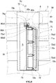
- the drum cleaning unit 7 will be described in detail below, and abuts against the outer surface 40 of the dewatering drum 4 as shown in FIG. 2 . Therefore, when the drum cleaning unit 7 abuts against the outer surface 40 of the dewatering drum 4, the motor 61 drives the dewatering drum 4 to rotate, so that the outer surface 40 of the dewatering drum 4 is cleaned with the friction by the drum cleaning unit 7. Moreover, the drum cleaning unit 7 and the outer surface 40 of the dewatering drum 4 during drum cleaning illustrated with double dot dash lines in FIG. 1 can be known from the outer side of the washing machine body 2 via the window portion 24 of the washing machine body 2 and the transparent area 32 of the outer drum 3.
- the state of the outer surface 40 of the dewatering drum 4 can be observed without disassembling the washing machine 1, and the time for cleaning the drum can be easily determined. Moreover, a cleaning condition of the drum can be observed and a cleaning effect of the drum can be easily known.
- FIG. 4 and FIG. 5 specifically illustrate the structure of the drum cleaning unit 7.
- FIG. 4 is a diagram illustrating the drum cleaning unit 7 viewed from the inner side of the outer drum 3.
- FIG. 5 is a longitudinal section view schematically illustrating the drum cleaning unit 7.
- FIG. 6 is a diagram illustrating displacement of the drum cleaning unit 7.
- the drum cleaning unit 7 has a supporting shaft portion 70, a brush portion 71 and a connection portion 72.
- the supporting shaft portion 70 penetrates through a through hole 76b formed in an upper surface 76a of the protruding portion 76 in an accommodating space S formed by the protruding portion 76 of the isolating unit 75, and extends in the direction parallel to the rotating shaft S of the dewatering drum 4, i.e. a vertical direction.
- the brush portion 71 is separately arranged in a direction orthogonal to the direction of the rotating shaft S, i.e. a horizontal direction and extends in the vertical direction.
- connection portion 72 connects the supporting shaft portion 70 and the brush portions 71, and has horizontal portions 72a horizontally extending from multiple positions (4 positions in the present embodiment) in the vertical direction of the supporting shaft portion 70 and a supporting portion 72b connected to the horizontal portions 72a and forming the brush portion 71 on a surface opposite to the dewatering drum 4.
- the brush portion 71 is formed by a plurality of hairy members (for example, made of nylon) fixed at the supporting portion 72b in a riveting manner. Furthermore, an opening portion 72a2 is formed between such horizontal portions 72a, and the brush portion 71 can be confirmed from the outer side of the washing machine body 2 via the opening portion 72a2.
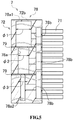
- a water path 78 including a main stream portion 78a and a plurality of injection portions 78b is formed in the supporting portion 72b of the connection portion 72.
- the main stream portion 78a has a diameter ⁇ 1 to ⁇ 3 which is gradually reduced from a start end 78a1 to a tail end 78a2, and extends along the direction parallel to the rotating shaft S (referring to FIG. 3 ) of the dewatering drum 4.
- the injection portions 78b are opened towards the brush portion 71 from the main stream portion 78a and formed at a plurality of positions along the direction parallel to the rotating shaft S (referring to FIG. 3 ) of the dewatering drum 4.
- a plurality of throttling porous plates 79 are separately configured in the middle of the main stream portion 78a, and the diameter of the main stream portion 78a is gradually reduced via the throttling porous plates 79.
- the water path 78 penetrates through the horizontal portions 72a (referring to FIG. 4 ) from the start end 78a1 of the main stream portion 78a to extend to the supporting shaft portion 70, and is connected to the other end 91 of the water supply pipe 9a (referring to FIG. 3 ).
- the water supplied by the water supply pipe 9a is supplied to the main stream portion 78a from the start end 78a1 and is injected through the injection portion 78b.
- the abutting/separating unit 8 has a spiral spring member (spring) 80d arranged at the upper end of the supporting shaft portion 70 of the drum cleaning unit 7, a torque motor 80 arranged at the upper end of the base plate portion 77, a linear member 80b with one end side 80b1 connected (twined) to a rotating portion 80a of the torque motor 80 and a rotating member 80c with a base end portion 80c1 fixed at the supporting shaft portion 70.
- the torque motor 80 is arranged at the upper end and the other side of the base plate portion 77, so that the torque motor 80 is prevented from contacting water.
- An end 80d1 of the spiral spring member 80d abuts against one side of the base plate portion 77 of the isolating unit 75, and as shown in FIG. 4 , the other end side 80d2 is fixed at a fixing slot 72a1 formed at the connection portion 72 of the drum cleaning unit 7.
- the spiral spring member 80d can press the connection portion 72 towards the base plate portion 77 of the spacer unit 75 through an elastic force.
- the rotating member 80c is arranged to fix the other end 80b2 of the linear component 80b.
- the rotating component 80c rotates towards the side of the torque motor 80 with the base end portion 80c1 as a base point. Since the base end portion 80c1 of the rotating member 80c is fixed at the supporting shaft portion 70 of the drum cleaning unit 7, along with the rotation of the rotating member 80c, the supporting shaft portion 70 may also resist the elastic force of the spiral spring member 80d to rotate. Therefore, as shown in FIG.
- the drum cleaning unit 7 rotates about the supporting shaft portion 70 at a specified angle (about 20 to 60 degrees) from a separated state that the brush portion 71 is separated from the outer surface 40 of the dewatering drum 4. As shown by double dot dash lines in FIG. 3 , the displacement occurs in a state that a top end portion 71 a of the brush portion 71 abuts against the outer surface 40 of the dewatering drum 4. When the torque motor 80 stops to drive, the drum cleaning unit 7 in an abutted state is changed to a separated state through the elastic force of the spiral spring member 80d.
- the drum cleaning unit 7 is preferably in the separated state, and preferably, the drum cleaning unit 7 is accommodated in the washing machine 1 in a manner of having displacement. Therefore, as described above, by adopting the structure in which the drum cleaning unit 7 is enabled to rotate about the supporting shaft portion 70 between the abutting position and the separating position by the abutting/separating unit 8, the space for accommodating the drum cleaning unit 7 in the washing machine body 2 is small, so that the upsizing of the washing machine 1 caused by the installation of the drum cleaning unit 7 can be prevented.
- the driving force for enabling the drum cleaning unit 7 to rotate is applied by the torque motor 80, so that compared with the situation of using a stepper motor, the microcomputer control is simple. Moreover, different from the situation of using the stepper motor, the dislocation of the drum cleaning unit 7 caused by the rotating and pushing of the dewatering drum 4 does not need to be concerned. Therefore, a position sensing unit of the drum cleaning unit 7 is not needed.
- a program for the drum cleaning process can be executed through the on/off of a power supply of the torque motor 80 and simple microcomputer control, so that cost can be reduced, and development working hours can be reduced.
- FIG. 7 is a perspective view illustrating the washing machine 1 with the drum cleaning assembly 7U being removed.
- the above drum cleaning assembly 7U is configured to be detachable from the washing machine body 2 through an insertion opening 23b presented when the control board 23a is removed from the washing machine body 2, and is configured to be capable of maintaining the drum cleaning unit 7. Therefore, the washing machine body 2 is provided with a connector (not shown) for assembling the drum cleaning assembly 7U.
- the other end 91 (referring to FIG. 3 ) of the water supply pipe 9a is detached from the supporting shaft 70.
- FIG. 8 is a block diagram illustrating an electric structure of the washing machine 1 according to the present embodiment.
- the action of the washing machine 1 is controlled by a control portion 95 including a microcomputer.
- the control portion 95 has a ROM71 and a RAM72, and a program stored in the ROM71 is executed through the microcomputer, thereby performing a preset operation action.
- the RAM72 is configured to temporarily store data used when the above program is executed and the like.
- control portion 95 is connected with a water supply valve 24 for supplying water to the outer drum 3, a drain valve 25 for discharging the water in the outer drum 3 and the drum cleaning water supply valve 27 and the like, where the water supply valve, the drain valve and the drum cleaning water supply valve are served as control objects.
- a water supply valve 24 for supplying water to the outer drum 3
- a drain valve 25 for discharging the water in the outer drum 3 and the drum cleaning water supply valve 27 and the like, where the water supply valve, the drain valve and the drum cleaning water supply valve are served as control objects.
- the water supply valve 24, the drain valve 25 and the drum cleaning water supply valve 27 are not shown in FIG. 2 .
- a water level sensor 29 is input to the control portion 95.
- the reed switch SW26 is configured to determine whether the brush portion 71 of the drum cleaning unit 7 contacts the outer surface 40 of the dewatering drum 4.
- FIG. 9 illustrates a drum cleaning process performed by the washing machine 1 according to the present embodiment.
- FIG. 9 is a flow chart illustrating a flow of the drum cleaning process.
- step SP1 the control portion 95 determines whether a drum cleaning mode button of the input portion 23 is pressed, and a drum cleaning instruction is input.
- step SP2 when receiving the input drum cleaning instruction, the control portion 95 determines whether the upper cover 22 is closed. The process proceeds to step SP3 when the upper cover is determined to be not closed (step SP2: No), and the process proceeds to step SP4 when the upper cover 22 is determined to be closed (step SP2: yes).
- step SP3 the control portion 95 enables the input portion 23 to display an error indicating that the upper cover 22 is open.
- step SP4 when determining that the upper cover 22 is closed, the control portion 95 enables the drain valve 25 to be opened.
- step SP5 the control portion 95 enables the drum cleaning water supply valve 27 to be opened.
- step SP6 the control portion 95 enables the torque motor 80 to rotate, so as to cause the drum cleaning unit 7 to be in the abutting state shown by the double dot dash lines in FIG. 6 relative to the outer surface 40 of the dewatering drum 4.
- step SP7 the control portion 95 determines whether the reed switch SW26 is changed to be on, thereby determining whether the drum cleaning unit 7 rotates and the electric brush portion 71 abuts against the outer surface 40 of the dewatering drum 4.
- step SP8 when the reed switch SW26 is changed to be on, the control portion 95 inputs a signal to the motor 61 to drive the dewatering drum 4 to rotate. It shall be noted that a rotation speed of the dewatering drum 4 at this moment is lower than the rotation speed of the dewatering drum 4 in dewatering.
- step SP9 the control portion 95 determines whether the timer 28 has timed for specified time, thereby determining whether a preset drum cleaning timing is reached.
- step SP10 when the timer 28 has timed for the specified time, the control portion 95 inputs a signal to the motor 61 to stop the dewatering drum 4 from rotating.
- step SP11 the control portion 95 causes the torque motor 80 to stop rotating, so as to cause the drum cleaning unit 7 to be separated from the dewatering drum 4.
- step SP12 the control portion 95 causes the drum cleaning water supply valve 27 to be closed.
- step SP13 the control portion 95 causes the drain valve 25 to be closed. So far, the drum cleaning process is ended.
- the state of the outer surface 40 of the dewatering drum 4 is known by the user via the window portion 24 of the washing machine body 2, and the drum cleaning can be performed at any timing, or the drum cleaning can also be set as that after operation for specified cycling times, a display lamp arranged on the input portion 23 is enabled to display (a timestamp carrying function), and the drum cleaning process is performed at the moment when the user confirms the display of the display lamp.
- a timestamp carrying function Through the timestamp carrying function, the dirty state of the outer surface 40 of the dewatering drum 4 will not be neglected.
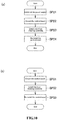
- FIG. 10 illustrates a disassembling/assembling process of the drum cleaning unit 7U, for example, for maintenance.
- FIG. 10 is a flow chart illustrating a flow of replacing the drum cleaning unit 7.
- FIG. 10(a) is a flow chart illustrating a flow of removing the drum cleaning assembly 7U.
- step SP21 a power supply of the washing machine is switched off.
- step SP22 as shown in FIG. 7 , the control board 23a is detached from the washing machine body 2.
- step SP23 the drum cleaning assembly 7U is removed upwards.
- step SP24 the control board 23a is assembled to the washing machine body 2 at an original position of the control board 23a.
- FIG. 10(b) is a flow chart illustrating a flow of assembling the drum cleaning assembly 7U.
- step SP31 as shown in FIG. 7 , the control board 23a is detached from the washing machine body 2.
- step SP32 the drum cleaning assembly 7U is assembled to the washing machine body 2 from top.
- step SP33 the control board 23a is assembled to the washing machine body 2.
- the drum cleaning unit 7 as the drum cleaning assembly 7U can be detached from the washing machine body 2.
- the drum cleaning unit 7 may also adopt a structure of the washing machine 1A shown in FIG. 11 in which the drum cleaning unit 7 cannot be detached from the washing machine body 2.
- FIG. 11 is a perspective view illustrating the washing machine 1A according to a modification example.
- FIG. 11 illustrates the outer drum 3 of the washing machine 1A and peripheries of the outer drum 3.
- the upper portion of the accommodating portion 31A of the outer drum 3 is not opened, but the accommodating portion 3A is integrally formed with the outer drum body 30A.
- the torque motor 80 is assembled at the upper end of the outer drum 3.
- the isolating unit 75 shown in FIG. 3 is not arranged, and a through hole (not shown) communicating the water supply pipe 9a and the supporting shaft portion 70 of the drum cleaning unit 7 is formed on the upper surface 31A1 of the accommodating portion 31A.
- the through hole is necessary for transferring a driving force of the torque motor 80 arranged at the outer surface of the outer drum 3 to the drum cleaning unit 7 arranged at the inner side of the outer drum 3; and by forming the through hole at the upper portion of the outer drum 3, a water leakage risk from the outer drum 3 via the through hole can be reduced.
- the front plate 31A2 of the accommodating portion 31A i.e. the portion corresponding to the window portion 24 (referring to FIG. 1 ) of the washing machine body 2
- the transparent member i.e. the portion corresponding to the window portion 24 (referring to FIG. 1 ) of the washing machine body 2
- the transparent area 32A perspective to the drum cleaning unit 7 and the outer surface 40 of the dewatering drum 4 is formed through the transparent member.
- the transparent area 32A is an area formed by embedding the transparent member into the opening window 31A3 opened at the front plate 31A2 of the accommodating portion 31A.
- the dewatering drum 4 is formed by a non-transparent member, and a structure that at least a portion of the dewatering drum 4 is formed by the transparent member can also be adopted.
- the transparent member can be made of polyethylene terephthalate (PET), polyethylene naphthalate (PEN), polycarbonate (PC) and the like.
- the reed switch SW, Hall IC and the like perform the control in such a manner that the position of the window portion of the dewatering drum 4 always corresponds to the window portion 24 of the washing machine body 2 in temporary stop and washing ended.
- the brush portion 71 is formed by a plurality of hairy members.
- the brush portion is not limited to the hairy members and can also be other members such as sponge materials, fiber members and the like as long as the structure can abut against the outer surface 40 of the dewatering drum 4 to remove dirt.
- the abutting/separating unit 8 is a structure with the torque motor 80 and may also be a structure with other motors such as a stepper motor.
- the drum cleaning unit 7 is not limited to the structure from which the water is injected, and may also adopt the structure that the drum cleaning process is performed in a state that the outer drum 3 stores water. Furthermore, the drum cleaning unit 7 may also be a non-rotating structure.
- the window portion 24 is formed at the front plate 2a of the washing machine body 2, but not limited to the front plate 2a, may also be formed at a transverse plate, and may also be formed at the front plate 2a and the transverse plate. Moreover, the shape of the window portion 24 is not limited to the general rectangle and may also be an oval shape.
- drum cleaning unit 7 is applicable to the vertical washing machine 1, but such drum cleaning unit 7 is also applicable to drum washing machines.
Landscapes
- Engineering & Computer Science (AREA)
- Textile Engineering (AREA)
- Main Body Construction Of Washing Machines And Laundry Dryers (AREA)
- Accessory Of Washing/Drying Machine, Commercial Washing/Drying Machine, Other Washing/Drying Machine (AREA)
- Detail Structures Of Washing Machines And Dryers (AREA)
Abstract
Description
- The present disclosure relates to a washing machine capable of learning about a cleaning condition on an outer surface of a dewatering drum from an outer side of a body of a washing machine.
- Generally, washings and detergents are thrown into a dewatering drum rotatably accommodated in an outer drum of a washing machine to begin to wash. Water supplied into the dewatering drum flows towards the outer drum via a plurality of water through holes formed in the dewatering drum. Therefore, an outer surface of the dewatering drum is in a state of being immersed in washing water and rinsing water during a washing process. Moreover, after dewatering, dirt attached to the washings and a portion of detergent residues may also remain accumulated at the outer surface of the dewatering drum and are used as a nutrient source to generate mold (mainly black mold) at the outer surface of the dewatering drum.
- As for an ordinary washing machine, it is hard to learn about the state of the outer surface of the dewatering drum without detaching the dewatering drum from the body of the washing machine body. However, the dewatering drum is connected with a motor served as a rotational drive mechanism, and is difficult to be detached by a user.
- Therefore, the dirt and mold on the outer surface of the dewatering drum are generally removed through a chemical method by throwing anti-mold preservative for cleaning the drum into the washing machine and performing a washing operation in, for example, a drum cleaning mode. However, in view of water pollution caused by the anti-mold preservative, economic efficiency, removal efficiency of the dirt and the like, a mechanical method is better than the chemical method realized through the anti-mold preservative.
- As the mechanical method for cleaning the dewatering drum,
patent literature 1 discloses a washing machine having a brush for cleaning an outer surface of a dewatering drum. In the washing machine disclosed inpatent literature 1, a dewatering drum which is circular viewed from the top is arranged in an outer drum which is rectangular viewed from the top, and a brush abutted against the outer surface of the dewatering drum is arranged at a corner of the outer drum forming a dead corner. - Patent literature 1: Japanese Patent application Laid-Open No.
6-47188 - However, as for the washing machine disclosed in
patent literature 1, it is hard to learn about the state of the outer surface of the dewatering drum without detaching the dewatering drum from the body of the washing machine. Accordingly, a dirty condition of the dewatering drum cannot be easily known, and thus it is difficult to determine the time for cleaning the dewatering drum. Moreover, the drum cleaning process performed by the brush cannot be directly observed, and it is inconvenient to learn about the drum cleaning effect. - The present disclosure aims to effectively solve such problems, and specifically, aims to provide a washing machine capable of observing a state of an outer surface of a dewatering drum without disassembling the washing machine, capable of easily determining the time for cleaning the drum, capable of observing the cleaning condition of the drum and capable of easily learning about a cleaning effect of the drum.
- In order to achieve related objective, the present disclosure adopts the following solution.
- That is, a washing machine of the present disclosure includes: a washing machine body, a side plate of the washing machine body is provided with a window portion; an outer drum, the outer drum is arranged in the washing machine body, and has at least a transparent area formed by a transparent member at a portion corresponding to the window portion; a dewatering drum rotatably arranged in the outer drum; a motor, configured to rotate to drive the dewatering drum; and a drum cleaning unit, the drum cleaning unit is arranged between the outer drum and the dewatering drum and disposed at a position corresponding to the window portion and the transparent area, and is capable of abutting against an outer surface of the dewatering drum.
- Furthermore, the present disclosure preferably adopts a structure as follows: the drum cleaning unit includes a supporting shaft portion extending along a direction parallel to a rotating shaft of the dewatering drum; and a brush portion separately arranged in a direction orthogonal to the rotating shaft relative to the supporting shaft portion; and the washing machine includes an abutting/separating unit configured to cause the drum cleaning unit to rotate about the supporting shaft portion, so as to make the drum cleaning unit in an abutted state or a separated state, the abutted state refers to a state that the brush portion abuts against the outer surface of the dewatering drum, and the separated state refers to a state that the brush portion is separated from the outer surface of the dewatering drum.
- Further, the present disclosure preferably adopts a structure as follows: the abutting/separating unit includes a torque motor, and a driving force for driving the drum cleaning unit to rotate is applied by the torque motor.
- Specifically, the present disclosure preferably adopts a structure as follows: the drum cleaning unit includes a connection portion connecting the brush portion and the supporting shaft portion, a water path having a main stream portion and a plurality of injection portions is formed in the connection portion, the main stream portion is gradually reduced in diameter from a start end to a tail end, and extends along the direction parallel to the rotating shaft of the dewatering drum, and the plurality of injection portions open from the main stream portion to the brush portion and are formed at a plurality of positions along the direction parallel to the rotating shaft of the dewatering drum respectively, and the washing machine includes a water supply unit for supplying water to the main stream portion from the start end.
- Furthermore, the present disclosure preferably adopts a structure as follows: the drum cleaning unit is configured to be detachable between the outer drum and the dewatering drum.
- Moreover, the present disclosure preferably adopts the structure as follows: at least a portion of the dewatering drum is formed by a transparent member.
- According to the present disclosure described above, in a state that the drum cleaning unit abuts against the outer surface of the dewatering drum, the motor causes the dewatering drum to rotate, so that the outer surface of the dewatering drum can be cleaned by virtue of the friction of the drum cleaning unit, and the outer surface of the dewatering drum can be known from the outer side of the washing machine body via the window portion of the washing machine body and the transparent area of the outer drum. Therefore, the state of the outer surface of the dewatering drum can be observed without disassembling the washing machine, the timing for cleaning the drum can be easily determined, a cleaning condition of the drum can be observed and a cleaning effect of the drum can be easily known.
- Furthermore, according to the present disclosure having the abutting/separating unit, the abutting/separating unit causes the drum cleaning unit to rotate about the supporting shaft portion between an abutting position and a separating position. Thus, a space for accommodating the drum cleaning unit in the washing machine body is small, and the upsizing of the washing machine caused by assembling the drum cleaning unit can be inhibited.
- Further, according to the present disclosure that the abutting/separating unit has the torque motor, and compared with a situation that the abutting/separating unit has a stepper motor, the drum cleaning is easier to control.
- Specifically, according to the present disclosure that the water path having the main stream portion and the injection portion is formed in the connection portion of the drum cleaning unit, the water is supplied to the water path in the connection portion through the water supply unit, so that the water can be injected from the connection portion at substantially-uniform pressure. Therefore, when the drum is cleaned, the water does not need to be stored in the outer drum, the drum can be cleaned by using little water, and the brush portion can be cleaned while the drum is cleaned by utilizing the water injected from the injection portion.
- Furthermore, according to the present disclosure that the drum cleaning unit is detachable between the outer drum and the dewatering drum, the maintenance of the drum cleaning unit can be performed.
- Further, according to the present disclosure that at least a portion of the dewatering drum is formed by the transparent member, both the cleaned condition of the dewatering drum and the washed condition of the clothes, and the like in the dewatering drum can be known from the outer side of the washing machine body via the window portion, the transparent area and the dewatering drum.
-
-
FIG. 1 is a perspective view illustrating an appearance of a washing machine according to an embodiment of the present disclosure. -
FIG. 2 is a longitudinal section view illustrating a rough structure of a washing machine according to the present disclosure. -
FIG. 3 is a perspective view illustrating a structure of an outer drum possessed by a washing machine of the present disclosure and peripheries of the outer drum. -
FIG. 4 is a diagram illustrating a drum cleaning unit of the washing machine of the present disclosure viewed from an inner side of an outer drum. -
FIG. 5 is a longitudinal section view schematically illustrating a drum cleaning unit of the present disclosure. -
FIG. 6 is a diagram illustrating displacement of a drum cleaning unit of the present disclosure. -
FIG. 7 is a perspective view illustrating a washing machine of the present disclosure with a drum cleaning assembly being removed. -
FIG. 8 is block diagram illustrating an electric structure of a washing machine according to the present disclosure. -
FIG. 9 is a flow chart illustrating a drum cleaning flow executed by a washing machine according to the present disclosure. -
FIG. 10 is a flow chart illustrating a disassembling/assembling flow of the drum cleaning assembly. -
FIG. 11 is a local perspective view illustrating a modification example of a washing machine of the present disclosure. -
- 1, 1A: washing machine
- 2: washing machine body
- 2a: side plate (front plate)
- 3: outer drum
- 4: dewatering drum
- 7: drum cleaning unit
- 8: abutting/separating unit
- 9: water supply unit
- 24: window portion
- 32: transparent area
- 61: motor
- 40: outer surface of the dewatering drum
- 70: supporting shaft portion
- 71: brush portion
- 72: connection portion
- 78: water path
- 78a: main stream portion
- 78b: injection portion
- 78a1: start end of main stream portion
- 78a2: tail end of main stream portion
- 80: torque motor
- S: rotating shaft of the dewatering drum
- ϕ1 to ϕ3: diameter of the main stream portion
- Embodiments of the present disclosure are described below with reference to drawings.
-
FIG. 1 is a perspective view illustrating an appearance of a vertical washing machine 1 (hereinafter referred to as "washing machine") according to an embodiment of the present disclosure.FIG. 2 is a longitudinal section view illustrating a rough structure of thewashing machine 1 according to the present embodiment.FIG. 3 is a perspective view illustrating a structure of anouter drum 3 and peripheries of theouter drum 3. - The
washing machine 1 includes awashing machine body 2, anouter drum 3, a dewatering drum 4, a drivingapparatus 6, adrum cleaning assembly 7U, a water supply unit 9 (referring toFIG. 3 ) and a control portion served as a control unit described below. - The
washing machine body 2 is of an approximately cuboid shape and is configured as follows: anopening 21 and anupper cover 22 for opening and closing theopening 21 are provided on anupper surface 20 of thewashing machine body 2. Clothes as washings can be thrown into/taken out of the dewatering drum 4 via theopening 21 by opening theupper cover 22. Theupper surface 20 of thewashing machine body 2 is further provided with aninput portion 23 formed by acontrol board 23a having an operation starting button, a drum cleaning mode button described below and the like. Thecontrol board 23a is configured to be detachable from the washing machine body 2 (referring toFIG. 7 ). Moreover, afront plate 2a served as a side plate of thewashing machine body 2 is formed with an approximatelyrectangular window portion 24 in which a transparent member is embedded. The transparent member is made of polyethylene terephthalate (PET), polyethylene naphthalate (PEN), polycarbonate (PC) and the like. - As shown in
FIG. 3 , theouter drum 3 is configured inside thewashing machine body 2, and is an approximately cylindrical component with a bottom. Theouter drum 3 is capable of storing water, and has anouter drum body 30 and anaccommodating portion 31 for accommodating thedrum cleaning assembly 7U. - The
outer drum body 30 is of a bottomed cylindrical shape, and a portion of aside surface 30b and theupper surface 30a is cut to form a notch along a direction parallel to a rotating shaft S of the dewatering drum 4. - The
accommodating portion 31 is protruded from a notch end 30a1 of theside surface 30b to a radial outside of the outer drummain body 30. Theaccommodating portion 31 is substantially of a rectangular shape in the top view. Furthermore, anotch 31a is formed at the upper end of theaccommodating portion 31, so that atorque motor 80 included in thedrum cleaning assembly 7U described below is mounted on theaccommodating portion 31. Furthermore, awater supply pipe 9a for supplying water to a drum cleaning apparatus in thedrum cleaning assembly 7U described below is arranged along theupper surface 30a of the outer drummain body 30. Anend 90 of thewater supply pipe 9a is disposed near awater supply port 92 for supplying water into theouter drum 3, and theother end 91 of thewater supply pipe 9a is disposed at a connection portion with thedrum cleaning assembly 7U. Thewater supply pipe 9a together with a drum cleaningwater supply valve 27 form awater supply unit 9. - In the present embodiment, the
outer drum 3 is almost integrally formed by the transparent member, and atransparent area 32 is formed in a portion corresponding to thewindow portion 24 of thewashing machine body 2. It shall be noted that the portion corresponding to thewindow portion 24 refers to a portion that can be observed via thewindow portion 24 from the outer side of thewashing machine body 2.FIG. 3 shows thedrum cleaning assembly 7U perspective from theaccommodating portion 31, and omits illustration of the dewatering drum 4 perspective from theouter drum body 30. This is the same inFIG. 1 andFIG. 4 . The transparent member can be made of polyethylene terephthalate (PET), polyethylene naphthalate (PEN), polycarbonate (PC) and the like. - The dewatering drum 4 is a bottomed cylindrical member arranged inside the
outer drum 3, and is capable of coaxially rotating with theouter drum 3. A diameter of the dewatering drum 4 is smaller than a diameter of theouter drum 3, and a wall surface of the dewatering drum 4 has a plurality of throughholes 3a. In dewatering, water flows outside from a water outlet (not shown) disposed on theouter drum 3 via the throughholes 3a. In order to ensure a space for accommodating adrum cleaning unit 7 described below, compared with the dewatering drum generally adopted in a conventional washing machine, a dewatering drum smaller in diameter relative to the dimension of theouter drum 3 is adopted as the dewatering drum 4. Furthermore, the washing machine body 2 (a housing) and theouter drum 3 may also adopt the following structure: compared with the conventional washing machine body and the outer drum, thewashing machine body 2 and theouter drum 3 is greater in diameter relative to the dimension of the dewatering drum 4 so as to ensure the space for accommodating thedrum cleaning unit 7. - As shown in
FIG. 2 , an impeller (stirring blade) 5 is rotatably configured at the center of a bottom 41 of the dewatering drum 4. Theimpeller 5 stirs the water accumulated at theouter drum 3 so as to generate a water flow. - A driving
unit 6 includes amotor 61 and a clutch 62. Themotor 61 enables the dewatering drum 4 and theimpeller 5 to rotate, so that a driving force for causing the washings accommodated in the dewatering drum 4 to rotate is applied. - Specifically, a driving
shaft 63 protruding from the bottom 41 of the dewatering drum 4 is driven to rotate by themotor 61, so as to drive the dewatering drum 4 to rotate. Furthermore, a rotating force generated by themotor 61 is applied to theimpeller 5 by the switching the clutch 62, so as to drive theimpeller 5 to rotate. Therefore, when thewashing machine 1 washes the clothes, only theimpeller 5 is enabled to rotate, and when in dewatering, the dewatering drum 4 and theimpeller 5 are rotated integrally at high speed. - As shown in
FIG. 3 , thedrum cleaning assembly 7U configured between theouter drum 3 and the dewatering drum 4 and configured at a position corresponding to thewindow portion 24 and thetransparent area 32, i.e., theaccommodating portion 31 of theouter drum 3, has thedrum cleaning unit 7, an abutting/separating unit 8 and an isolatingunit 75. One side surface of the isolatingunit 75 is provided with thedrum cleaning unit 7, the other side surface of the isolatingunit 75 is provided with atorque motor 80 of the abutting/separating unit 8; and the isolatingunit 75 has aplate portion 77 of an approximately rectangular plate-like base and a protrudingportion 76 protruding to the outside of theouter drum 3 from thebase plate portion 77 in a radial direction. - The
drum cleaning unit 7 will be described in detail below, and abuts against theouter surface 40 of the dewatering drum 4 as shown inFIG. 2 . Therefore, when thedrum cleaning unit 7 abuts against theouter surface 40 of the dewatering drum 4, themotor 61 drives the dewatering drum 4 to rotate, so that theouter surface 40 of the dewatering drum 4 is cleaned with the friction by thedrum cleaning unit 7. Moreover, thedrum cleaning unit 7 and theouter surface 40 of the dewatering drum 4 during drum cleaning illustrated with double dot dash lines inFIG. 1 can be known from the outer side of thewashing machine body 2 via thewindow portion 24 of thewashing machine body 2 and thetransparent area 32 of theouter drum 3. Therefore, the state of theouter surface 40 of the dewatering drum 4 can be observed without disassembling thewashing machine 1, and the time for cleaning the drum can be easily determined. Moreover, a cleaning condition of the drum can be observed and a cleaning effect of the drum can be easily known. -
FIG. 4 andFIG. 5 specifically illustrate the structure of thedrum cleaning unit 7.FIG. 4 is a diagram illustrating thedrum cleaning unit 7 viewed from the inner side of theouter drum 3.FIG. 5 is a longitudinal section view schematically illustrating thedrum cleaning unit 7.FIG. 6 is a diagram illustrating displacement of thedrum cleaning unit 7. As shown inFIG. 4 , thedrum cleaning unit 7 has a supportingshaft portion 70, abrush portion 71 and aconnection portion 72. - The supporting
shaft portion 70 penetrates through a throughhole 76b formed in anupper surface 76a of the protrudingportion 76 in an accommodating space S formed by the protrudingportion 76 of the isolatingunit 75, and extends in the direction parallel to the rotating shaft S of the dewatering drum 4, i.e. a vertical direction. - Relative to the supporting
shaft portion 70, thebrush portion 71 is separately arranged in a direction orthogonal to the direction of the rotating shaft S, i.e. a horizontal direction and extends in the vertical direction. - The
connection portion 72 connects the supportingshaft portion 70 and thebrush portions 71, and hashorizontal portions 72a horizontally extending from multiple positions (4 positions in the present embodiment) in the vertical direction of the supportingshaft portion 70 and a supportingportion 72b connected to thehorizontal portions 72a and forming thebrush portion 71 on a surface opposite to the dewatering drum 4. Thebrush portion 71 is formed by a plurality of hairy members (for example, made of nylon) fixed at the supportingportion 72b in a riveting manner. Furthermore, an opening portion 72a2 is formed between suchhorizontal portions 72a, and thebrush portion 71 can be confirmed from the outer side of thewashing machine body 2 via the opening portion 72a2. - Furthermore, as shown in
FIG. 5 , awater path 78 including amain stream portion 78a and a plurality ofinjection portions 78b is formed in the supportingportion 72b of theconnection portion 72. Themain stream portion 78a has a diameter ϕ1 to ϕ3 which is gradually reduced from a start end 78a1 to a tail end 78a2, and extends along the direction parallel to the rotating shaft S (referring toFIG. 3 ) of the dewatering drum 4. Theinjection portions 78b are opened towards thebrush portion 71 from themain stream portion 78a and formed at a plurality of positions along the direction parallel to the rotating shaft S (referring toFIG. 3 ) of the dewatering drum 4. A plurality of throttlingporous plates 79 are separately configured in the middle of themain stream portion 78a, and the diameter of themain stream portion 78a is gradually reduced via the throttlingporous plates 79. Thewater path 78 penetrates through thehorizontal portions 72a (referring toFIG. 4 ) from the start end 78a1 of themain stream portion 78a to extend to the supportingshaft portion 70, and is connected to theother end 91 of thewater supply pipe 9a (referring toFIG. 3 ). The water supplied by thewater supply pipe 9a is supplied to themain stream portion 78a from the start end 78a1 and is injected through theinjection portion 78b. - Therefore, in the drum cleaning process, by supplying water to the
water path 78 having the throttlingporous plates 79 from thewater supply unit 9, water can be injected from the upper end portion to the lower end portion of theconnection portion 72 at substantially-uniform (equal) pressure. Therefore, when theouter surface 40 of the dewatering drum 4 is cleaned, compared with cleaning the drum in the state that theouter drum 3 is filled with water, water can be saved, and thebrush portion 71 is cleaned through the water injected from theinjection portion 78b. - Returning to
FIG. 3 , the abutting/separating unit 8 has a spiral spring member (spring) 80d arranged at the upper end of the supportingshaft portion 70 of thedrum cleaning unit 7, atorque motor 80 arranged at the upper end of thebase plate portion 77, alinear member 80b with one end side 80b1 connected (twined) to arotating portion 80a of thetorque motor 80 and a rotatingmember 80c with a base end portion 80c1 fixed at the supportingshaft portion 70. Thetorque motor 80 is arranged at the upper end and the other side of thebase plate portion 77, so that thetorque motor 80 is prevented from contacting water. - An end 80d1 of the
spiral spring member 80d abuts against one side of thebase plate portion 77 of the isolatingunit 75, and as shown inFIG. 4 , the other end side 80d2 is fixed at a fixing slot 72a1 formed at theconnection portion 72 of thedrum cleaning unit 7. Thespiral spring member 80d can press theconnection portion 72 towards thebase plate portion 77 of thespacer unit 75 through an elastic force. - As shown in
FIG. 3 , the rotatingmember 80c is arranged to fix the other end 80b2 of thelinear component 80b. When thetorque motor 80 drives and rolls up thelinear member 80b, the rotatingcomponent 80c rotates towards the side of thetorque motor 80 with the base end portion 80c1 as a base point. Since the base end portion 80c1 of the rotatingmember 80c is fixed at the supportingshaft portion 70 of thedrum cleaning unit 7, along with the rotation of the rotatingmember 80c, the supportingshaft portion 70 may also resist the elastic force of thespiral spring member 80d to rotate. Therefore, as shown inFIG. 6 , thedrum cleaning unit 7 rotates about the supportingshaft portion 70 at a specified angle (about 20 to 60 degrees) from a separated state that thebrush portion 71 is separated from theouter surface 40 of the dewatering drum 4. As shown by double dot dash lines inFIG. 3 , the displacement occurs in a state that atop end portion 71 a of thebrush portion 71 abuts against theouter surface 40 of the dewatering drum 4. When thetorque motor 80 stops to drive, thedrum cleaning unit 7 in an abutted state is changed to a separated state through the elastic force of thespiral spring member 80d. - Herein, if the
drum cleaning unit 7 is always in the abutted state, the conventional washing operation may apply a load to themotor 61. Therefore, except for the drum cleaning, thedrum cleaning unit 7 is preferably in the separated state, and preferably, thedrum cleaning unit 7 is accommodated in thewashing machine 1 in a manner of having displacement. Therefore, as described above, by adopting the structure in which thedrum cleaning unit 7 is enabled to rotate about the supportingshaft portion 70 between the abutting position and the separating position by the abutting/separating unit 8, the space for accommodating thedrum cleaning unit 7 in thewashing machine body 2 is small, so that the upsizing of thewashing machine 1 caused by the installation of thedrum cleaning unit 7 can be prevented. - Furthermore, the driving force for enabling the
drum cleaning unit 7 to rotate is applied by thetorque motor 80, so that compared with the situation of using a stepper motor, the microcomputer control is simple. Moreover, different from the situation of using the stepper motor, the dislocation of thedrum cleaning unit 7 caused by the rotating and pushing of the dewatering drum 4 does not need to be worried. Therefore, a position sensing unit of thedrum cleaning unit 7 is not needed. By adopting the structure that thedrum cleaning unit 7 is driven by thetorque motor 80 and thespiral spring member 80d to rotate, a program for the drum cleaning process can be executed through the on/off of a power supply of thetorque motor 80 and simple microcomputer control, so that cost can be reduced, and development working hours can be reduced. -
FIG. 7 is a perspective view illustrating thewashing machine 1 with thedrum cleaning assembly 7U being removed. As shown inFIG. 7 , the abovedrum cleaning assembly 7U is configured to be detachable from thewashing machine body 2 through aninsertion opening 23b presented when thecontrol board 23a is removed from thewashing machine body 2, and is configured to be capable of maintaining thedrum cleaning unit 7. Therefore, thewashing machine body 2 is provided with a connector (not shown) for assembling thedrum cleaning assembly 7U. In addition, when thedrum cleaning assembly 7U is removed, the other end 91 (referring toFIG. 3 ) of thewater supply pipe 9a is detached from the supportingshaft 70. -
FIG. 8 is a block diagram illustrating an electric structure of thewashing machine 1 according to the present embodiment. The action of thewashing machine 1 is controlled by acontrol portion 95 including a microcomputer. Thecontrol portion 95 has a ROM71 and a RAM72, and a program stored in the ROM71 is executed through the microcomputer, thereby performing a preset operation action. The RAM72 is configured to temporarily store data used when the above program is executed and the like. - Besides the
motor 61 and the clutch 62, thecontrol portion 95 is connected with awater supply valve 24 for supplying water to theouter drum 3, adrain valve 25 for discharging the water in theouter drum 3 and the drum cleaningwater supply valve 27 and the like, where the water supply valve, the drain valve and the drum cleaning water supply valve are served as control objects. It shall be noted that, thewater supply valve 24, thedrain valve 25 and the drum cleaningwater supply valve 27 are not shown inFIG. 2 . - Furthermore, besides signals from the
above input portion 23, signals from atimer 28, awater level sensor 29, a reed switch SW26 and the like are input to thecontrol portion 95. The reed switch SW26 is configured to determine whether thebrush portion 71 of thedrum cleaning unit 7 contacts theouter surface 40 of the dewatering drum 4. -
FIG. 9 illustrates a drum cleaning process performed by thewashing machine 1 according to the present embodiment.FIG. 9 is a flow chart illustrating a flow of the drum cleaning process. - In step SP1, the
control portion 95 determines whether a drum cleaning mode button of theinput portion 23 is pressed, and a drum cleaning instruction is input. - In step SP2, when receiving the input drum cleaning instruction, the
control portion 95 determines whether theupper cover 22 is closed. The process proceeds to step SP3 when the upper cover is determined to be not closed (step SP2: No), and the process proceeds to step SP4 when theupper cover 22 is determined to be closed (step SP2: yes). - In step SP3, the
control portion 95 enables theinput portion 23 to display an error indicating that theupper cover 22 is open. - In step SP4, when determining that the
upper cover 22 is closed, thecontrol portion 95 enables thedrain valve 25 to be opened. - In step SP5, the
control portion 95 enables the drum cleaningwater supply valve 27 to be opened. - In step SP6, the
control portion 95 enables thetorque motor 80 to rotate, so as to cause thedrum cleaning unit 7 to be in the abutting state shown by the double dot dash lines inFIG. 6 relative to theouter surface 40 of the dewatering drum 4. - In step SP7, the
control portion 95 determines whether the reed switch SW26 is changed to be on, thereby determining whether thedrum cleaning unit 7 rotates and theelectric brush portion 71 abuts against theouter surface 40 of the dewatering drum 4. - In step SP8, when the reed switch SW26 is changed to be on, the
control portion 95 inputs a signal to themotor 61 to drive the dewatering drum 4 to rotate. It shall be noted that a rotation speed of the dewatering drum 4 at this moment is lower than the rotation speed of the dewatering drum 4 in dewatering. - Therefore, water is injected via the
water inlet path 78 of thedrum cleaning unit 7, and theouter surface 40 of the dewatering drum 4 is rubbed by thetop end 71 a of thebrush portion 71, so that dirt and mold on theouter surface 40 of the dewatering drum 4 are washed away through a mechanical force. - In step SP9, the
control portion 95 determines whether thetimer 28 has timed for specified time, thereby determining whether a preset drum cleaning timing is reached. - In step SP10, when the
timer 28 has timed for the specified time, thecontrol portion 95 inputs a signal to themotor 61 to stop the dewatering drum 4 from rotating. - In step SP11, the
control portion 95 causes thetorque motor 80 to stop rotating, so as to cause thedrum cleaning unit 7 to be separated from the dewatering drum 4. - In step SP12, the
control portion 95 causes the drum cleaningwater supply valve 27 to be closed. - In step SP13, the
control portion 95 causes thedrain valve 25 to be closed. So far, the drum cleaning process is ended. - Through such drum cleaning process, the state of the
outer surface 40 of the dewatering drum 4 is known by the user via thewindow portion 24 of thewashing machine body 2, and the drum cleaning can be performed at any timing, or the drum cleaning can also be set as that after operation for specified cycling times, a display lamp arranged on theinput portion 23 is enabled to display (a timestamp carrying function), and the drum cleaning process is performed at the moment when the user confirms the display of the display lamp. Through the timestamp carrying function, the dirty state of theouter surface 40 of the dewatering drum 4 will not be neglected. - Next,
FIG. 10 illustrates a disassembling/assembling process of thedrum cleaning unit 7U, for example, for maintenance.FIG. 10 is a flow chart illustrating a flow of replacing thedrum cleaning unit 7.FIG. 10(a) is a flow chart illustrating a flow of removing thedrum cleaning assembly 7U. - In step SP21, a power supply of the washing machine is switched off.
- In step SP22, as shown in
FIG. 7 , thecontrol board 23a is detached from thewashing machine body 2. - In step SP23, the
drum cleaning assembly 7U is removed upwards. - In step SP24, the
control board 23a is assembled to thewashing machine body 2 at an original position of thecontrol board 23a. - Next,
FIG. 10(b) is a flow chart illustrating a flow of assembling thedrum cleaning assembly 7U. - In step SP31, as shown in
FIG. 7 , thecontrol board 23a is detached from thewashing machine body 2. - In step SP32, the
drum cleaning assembly 7U is assembled to thewashing machine body 2 from top. - In step SP33, the
control board 23a is assembled to thewashing machine body 2. - It shall be noted that a specific solution of each portion is not limited to the above embodiments.
- For example, in the present embodiment, the
drum cleaning unit 7 as thedrum cleaning assembly 7U can be detached from thewashing machine body 2. Alternatively, thedrum cleaning unit 7 may also adopt a structure of thewashing machine 1A shown inFIG. 11 in which thedrum cleaning unit 7 cannot be detached from thewashing machine body 2.FIG. 11 is a perspective view illustrating thewashing machine 1A according to a modification example.FIG. 11 illustrates theouter drum 3 of thewashing machine 1A and peripheries of theouter drum 3. - Specifically, the upper portion of the
accommodating portion 31A of theouter drum 3 is not opened, but the accommodating portion 3A is integrally formed with theouter drum body 30A. Thetorque motor 80 is assembled at the upper end of theouter drum 3. Furthermore, the isolatingunit 75 shown inFIG. 3 is not arranged, and a through hole (not shown) communicating thewater supply pipe 9a and the supportingshaft portion 70 of thedrum cleaning unit 7 is formed on the upper surface 31A1 of theaccommodating portion 31A. The through hole is necessary for transferring a driving force of thetorque motor 80 arranged at the outer surface of theouter drum 3 to thedrum cleaning unit 7 arranged at the inner side of theouter drum 3; and by forming the through hole at the upper portion of theouter drum 3, a water leakage risk from theouter drum 3 via the through hole can be reduced. - Moreover, the front plate 31A2 of the
accommodating portion 31A, i.e. the portion corresponding to the window portion 24 (referring toFIG. 1 ) of thewashing machine body 2, is formed by the transparent member, and the transparent area 32A perspective to thedrum cleaning unit 7 and theouter surface 40 of the dewatering drum 4 is formed through the transparent member. The transparent area 32A is an area formed by embedding the transparent member into the opening window 31A3 opened at the front plate 31A2 of theaccommodating portion 31A. - Furthermore, in the present embodiment, the dewatering drum 4 is formed by a non-transparent member, and a structure that at least a portion of the dewatering drum 4 is formed by the transparent member can also be adopted. The transparent member can be made of polyethylene terephthalate (PET), polyethylene naphthalate (PEN), polycarbonate (PC) and the like.
- Thus, not only the
outer surface 40 of the dewatering drum 4 and thedrum cleaning unit 7, but also the washed condition of the washings in the dewatering drum 4 can be known from the outer side of thewashing machine body 2 through thewindow portion 24, thetransparent area 32 and the dewatering drum 4, and water level adjustment during washing and the rinsing confirmation can also be performed. - Furthermore, in the case of adopting the structure that the window portion is formed at the dewatering drum 4 and the transparent member is embedded into the window portion, the reed switch SW, Hall IC and the like perform the control in such a manner that the position of the window portion of the dewatering drum 4 always corresponds to the
window portion 24 of thewashing machine body 2 in temporary stop and washing ended. - Furthermore, in the above embodiment, the
brush portion 71 is formed by a plurality of hairy members. However, the brush portion is not limited to the hairy members and can also be other members such as sponge materials, fiber members and the like as long as the structure can abut against theouter surface 40 of the dewatering drum 4 to remove dirt. - Furthermore, in the present embodiment, the abutting/
separating unit 8 is a structure with thetorque motor 80 and may also be a structure with other motors such as a stepper motor. - Moreover, the
drum cleaning unit 7 is not limited to the structure from which the water is injected, and may also adopt the structure that the drum cleaning process is performed in a state that theouter drum 3 stores water. Furthermore, thedrum cleaning unit 7 may also be a non-rotating structure. - Furthermore, in the present embodiment, the
window portion 24 is formed at thefront plate 2a of thewashing machine body 2, but not limited to thefront plate 2a, may also be formed at a transverse plate, and may also be formed at thefront plate 2a and the transverse plate. Moreover, the shape of thewindow portion 24 is not limited to the general rectangle and may also be an oval shape. - Moreover, in the present embodiment, the
drum cleaning unit 7 is applicable to thevertical washing machine 1, but suchdrum cleaning unit 7 is also applicable to drum washing machines. - Various variations can be made to other structures without going beyond a scope of technical spirit of the present disclosure.
Claims (6)
- A washing machine, comprising:a washing machine body, wherein a side plate of the washing machine body is provided with a window portion;an outer drum, wherein the outer drum is arranged in the washing machine body, and has at least a transparent area formed by a transparent member at a portion corresponding to the window portion;a dewatering drum rotatably arranged in the outer drum;a motor, configured to rotate to drive the dewatering drum; anda drum cleaning unit, wherein the drum cleaning unit is arranged between the outer drum and the dewatering drum and disposed at a position corresponding to the window portion and the transparent area, and is capable of abutting against an outer surface of the dewatering drum.
- The washing machine according to claim 1, whereinthe drum cleaning unit comprises a supporting shaft portion extending along a direction parallel to a rotating shaft of the dewatering drum; and a brush portion separately arranged in a direction orthogonal to the rotating shaft relative to the supporting shaft portion; andthe washing machine comprises an abutting/separating unit configured to cause the drum cleaning unit to rotate about the supporting shaft portion, so as to make the drum cleaning unit in an abutted state or a separated state, wherein the abutted state refers to a state that the brush portion abuts against the outer surface of the dewatering drum, and the separated state refers to a state that the brush portion is separated from the outer surface of the dewatering drum.
- The washing machine according to claim 2, wherein the abutting/separating unit comprises a torque motor, and a driving force for driving the drum cleaning unit to rotate is applied by the torque motor.
- The washing machine according to claim 2 or 3, whereinthe drum cleaning unit comprises a connection portion connecting the brush portion and the supporting shaft portion,a water path having a main stream portion and a plurality of injection portions is formed in the connection portion, wherein the main stream portion is gradually reduced in diameter from a start end to a tail end, and extends along the direction parallel to the rotating shaft of the dewatering drum, and the plurality of injection portions open from the main stream portion to the brush portion and are formed at a plurality of positions along the direction parallel to the rotating shaft of the dewatering drum respectively, andthe washing machine comprises a water supply unit for supplying water to the main stream portion from the start end.
- The washing machine according to any one of claims 1 to 3, wherein the drum cleaning unit is configured to be detachable between the outer drum and the dewatering drum.
- The washing machine according to any one of claims 1 to 3, wherein at least a portion of the dewatering drum is formed by a transparent member.
Applications Claiming Priority (2)
| Application Number | Priority Date | Filing Date | Title |
|---|---|---|---|
| JP2014262989A JP2016120161A (en) | 2014-12-25 | 2014-12-25 | Washing machine |
| PCT/CN2015/097813 WO2016101840A1 (en) | 2014-12-25 | 2015-12-18 | Washing machine |
Publications (2)
| Publication Number | Publication Date |
|---|---|
| EP3239385A1 true EP3239385A1 (en) | 2017-11-01 |
| EP3239385A4 EP3239385A4 (en) | 2018-08-29 |
Family
ID=56149256
Family Applications (1)
| Application Number | Title | Priority Date | Filing Date |
|---|---|---|---|
| EP15871908.8A Withdrawn EP3239385A4 (en) | 2014-12-25 | 2015-12-18 | Washing machine |
Country Status (6)
| Country | Link |
|---|---|
| US (1) | US20180057989A1 (en) |
| EP (1) | EP3239385A4 (en) |
| JP (1) | JP2016120161A (en) |
| KR (1) | KR20170098930A (en) |
| CN (1) | CN107109763B (en) |
| WO (1) | WO2016101840A1 (en) |
Families Citing this family (5)
| Publication number | Priority date | Publication date | Assignee | Title |
|---|---|---|---|---|
| CN109695131A (en) * | 2017-10-20 | 2019-04-30 | 东元电机股份有限公司 | With partial perspective type washing machine |
| CN112831988A (en) * | 2018-10-27 | 2021-05-25 | 苟会兵 | Cleaning device of full-automatic washing machine and using method |
| KR102634113B1 (en) | 2019-06-21 | 2024-02-05 | 엘지전자 주식회사 | Method, apparatus and system for detecting contamination of laundry tub using composite sensor |
| CN110404841B (en) * | 2019-07-23 | 2022-06-28 | 东华大学 | A scrubbing mechanism for a cylindrical car foot pad cleaning device |
| CN116657379A (en) * | 2023-06-29 | 2023-08-29 | 贾少博 | A kind of non-detachable self-cleaning drum washing machine |
Family Cites Families (10)
| Publication number | Priority date | Publication date | Assignee | Title |
|---|---|---|---|---|
| JP3222938B2 (en) * | 1992-07-29 | 2001-10-29 | 武彦 服部 | Washing machine |
| RU2191630C1 (en) * | 2001-06-09 | 2002-10-27 | Общество с ограниченной ответственностью "Кварц Т-2000" | Low-frequency acoustic generator |
| US7753009B2 (en) * | 2006-10-19 | 2010-07-13 | Whirlpool Corporation | Washer with bio prevention cycle |
| CN200981941Y (en) * | 2006-10-30 | 2007-11-28 | 杭州松下家用电器有限公司 | Cleaning device for the outer wall of the inner drum of the washing machine |
| JP2010036012A (en) * | 2008-08-07 | 2010-02-18 | Kyoko Onoda | Laundry machine visualizing fouling degree of water between outer and inner drums visible |
| CN201648773U (en) * | 2010-04-23 | 2010-11-24 | 陈哲 | Washing machine with function of cleaning barrel outer gap cleaning |
| CN203270313U (en) * | 2010-06-17 | 2013-11-06 | 宝洁公司 | Portable Micro Washing Machine |
| KR20130114970A (en) * | 2012-04-10 | 2013-10-21 | 강유성 | Cleaning apparatus of a washing machine |
| CN103343438A (en) * | 2013-07-10 | 2013-10-09 | 镇江市博林光电科技有限公司 | Washing machine with dirt removing function |
| CN203923719U (en) * | 2014-01-03 | 2014-11-05 | 海尔集团公司 | A kind of washing machine with transparent window |
-
2014
- 2014-12-25 JP JP2014262989A patent/JP2016120161A/en active Pending
-
2015
- 2015-12-18 CN CN201580070948.7A patent/CN107109763B/en active Active
- 2015-12-18 WO PCT/CN2015/097813 patent/WO2016101840A1/en not_active Ceased
- 2015-12-18 US US15/539,031 patent/US20180057989A1/en not_active Abandoned
- 2015-12-18 KR KR1020177020904A patent/KR20170098930A/en not_active Ceased
- 2015-12-18 EP EP15871908.8A patent/EP3239385A4/en not_active Withdrawn
Also Published As
| Publication number | Publication date |
|---|---|
| JP2016120161A (en) | 2016-07-07 |
| US20180057989A1 (en) | 2018-03-01 |
| EP3239385A4 (en) | 2018-08-29 |
| KR20170098930A (en) | 2017-08-30 |
| CN107109763B (en) | 2019-04-05 |
| CN107109763A (en) | 2017-08-29 |
| WO2016101840A1 (en) | 2016-06-30 |
Similar Documents
| Publication | Publication Date | Title |
|---|---|---|
| US20180057989A1 (en) | Washing machine | |
| AU2016269472B2 (en) | Detergent supplying device and washing machine having the same | |
| CN106917218B (en) | Washing machine | |
| EP3239386B1 (en) | Washing machine | |
| KR20150055512A (en) | Washing machine | |
| KR20160142048A (en) | Washing apparutus and controlling method thereof | |
| CN110685107A (en) | Ultrasonic devices and laundry treatment equipment | |
| KR20190090192A (en) | Washing Machine Internal Washing Device and Cleaning Method | |
| US10704177B2 (en) | Washing machine lid attachment | |
| KR20140131809A (en) | Detergent automatic providing apparatus and washing machine having the same | |
| CN103462573B (en) | A kind of mop-pail stands with cleaning device | |
| US9328445B2 (en) | Mode shifter with a leaf spring yoke for a washing machine appliance | |
| KR20130123557A (en) | Cleaning apparatus of drum washing machine | |
| KR100713946B1 (en) | Drum Washing Machine | |
| CN106460291A (en) | Washing machine | |
| CN105019189A (en) | Washing machine and partition plate | |
| EP3305964A1 (en) | Washing machine | |
| JP2013099393A (en) | Washing machine | |
| WO2015188683A1 (en) | Drum type washing machine | |
| US8857227B2 (en) | Status sensor for a clutch on a washing machine appliance | |
| JP2019088720A (en) | Washing machine | |
| WO2015184958A1 (en) | Drum washing machine | |
| CN101435145B (en) | Washings processing device | |
| JP2005334118A (en) | Washing machine | |
| KR102931243B1 (en) | Laundry Treating Apparatus |
Legal Events
| Date | Code | Title | Description |
|---|---|---|---|
| STAA | Information on the status of an ep patent application or granted ep patent |
Free format text: STATUS: THE INTERNATIONAL PUBLICATION HAS BEEN MADE |
|
| PUAI | Public reference made under article 153(3) epc to a published international application that has entered the european phase |
Free format text: ORIGINAL CODE: 0009012 |
|
| STAA | Information on the status of an ep patent application or granted ep patent |
Free format text: STATUS: REQUEST FOR EXAMINATION WAS MADE |
|
| 17P | Request for examination filed |
Effective date: 20170721 |
|
| AK | Designated contracting states |
Kind code of ref document: A1 Designated state(s): AL AT BE BG CH CY CZ DE DK EE ES FI FR GB GR HR HU IE IS IT LI LT LU LV MC MK MT NL NO PL PT RO RS SE SI SK SM TR |
|
| AX | Request for extension of the european patent |
Extension state: BA ME |
|
| DAV | Request for validation of the european patent (deleted) | ||
| DAX | Request for extension of the european patent (deleted) | ||
| RIC1 | Information provided on ipc code assigned before grant |
Ipc: D06F 37/26 20060101ALI20180719BHEP Ipc: B08B 1/00 20060101ALN20180719BHEP Ipc: D06F 37/12 20060101ALN20180719BHEP Ipc: D06F 35/00 20060101ALI20180719BHEP Ipc: D06F 39/12 20060101AFI20180719BHEP |
|
| A4 | Supplementary search report drawn up and despatched |
Effective date: 20180727 |
|
| STAA | Information on the status of an ep patent application or granted ep patent |
Free format text: STATUS: THE APPLICATION HAS BEEN WITHDRAWN |
|
| 18W | Application withdrawn |
Effective date: 20190129 |