EP3239380A1 - Washing machine - Google Patents
Washing machine Download PDFInfo
- Publication number
- EP3239380A1 EP3239380A1 EP15871907.0A EP15871907A EP3239380A1 EP 3239380 A1 EP3239380 A1 EP 3239380A1 EP 15871907 A EP15871907 A EP 15871907A EP 3239380 A1 EP3239380 A1 EP 3239380A1
- Authority
- EP
- European Patent Office
- Prior art keywords
- tub
- washing
- housing
- washing machine
- outer tub
- Prior art date
- Legal status (The legal status is an assumption and is not a legal conclusion. Google has not performed a legal analysis and makes no representation as to the accuracy of the status listed.)
- Withdrawn
Links
Images



Classifications
-
- D—TEXTILES; PAPER
- D06—TREATMENT OF TEXTILES OR THE LIKE; LAUNDERING; FLEXIBLE MATERIALS NOT OTHERWISE PROVIDED FOR
- D06F—LAUNDERING, DRYING, IRONING, PRESSING OR FOLDING TEXTILE ARTICLES
- D06F23/00—Washing machines with receptacles, e.g. perforated, having a rotary movement, e.g. oscillatory movement, the receptacle serving both for washing and for centrifugally separating water from the laundry
- D06F23/04—Washing machines with receptacles, e.g. perforated, having a rotary movement, e.g. oscillatory movement, the receptacle serving both for washing and for centrifugally separating water from the laundry and rotating or oscillating about a vertical axis
-
- D—TEXTILES; PAPER
- D06—TREATMENT OF TEXTILES OR THE LIKE; LAUNDERING; FLEXIBLE MATERIALS NOT OTHERWISE PROVIDED FOR
- D06F—LAUNDERING, DRYING, IRONING, PRESSING OR FOLDING TEXTILE ARTICLES
- D06F17/00—Washing machines having receptacles, stationary for washing purposes, wherein the washing action is effected solely by circulation or agitation of the washing liquid
- D06F17/06—Washing machines having receptacles, stationary for washing purposes, wherein the washing action is effected solely by circulation or agitation of the washing liquid by rotary impellers
-
- D—TEXTILES; PAPER
- D06—TREATMENT OF TEXTILES OR THE LIKE; LAUNDERING; FLEXIBLE MATERIALS NOT OTHERWISE PROVIDED FOR
- D06F—LAUNDERING, DRYING, IRONING, PRESSING OR FOLDING TEXTILE ARTICLES
- D06F37/00—Details specific to washing machines covered by groups D06F21/00 - D06F25/00
- D06F37/20—Mountings, e.g. resilient mountings, for the rotary receptacle, motor, tub or casing; Preventing or damping vibrations
- D06F37/24—Mountings, e.g. resilient mountings, for the rotary receptacle, motor, tub or casing; Preventing or damping vibrations in machines with a receptacle rotating or oscillating about a vertical axis
-
- D—TEXTILES; PAPER
- D06—TREATMENT OF TEXTILES OR THE LIKE; LAUNDERING; FLEXIBLE MATERIALS NOT OTHERWISE PROVIDED FOR
- D06F—LAUNDERING, DRYING, IRONING, PRESSING OR FOLDING TEXTILE ARTICLES
- D06F37/00—Details specific to washing machines covered by groups D06F21/00 - D06F25/00
- D06F37/30—Driving arrangements
- D06F37/40—Driving arrangements for driving the receptacle and an agitator or impeller, e.g. alternatively
-
- D—TEXTILES; PAPER
- D06—TREATMENT OF TEXTILES OR THE LIKE; LAUNDERING; FLEXIBLE MATERIALS NOT OTHERWISE PROVIDED FOR
- D06F—LAUNDERING, DRYING, IRONING, PRESSING OR FOLDING TEXTILE ARTICLES
- D06F37/00—Details specific to washing machines covered by groups D06F21/00 - D06F25/00
- D06F37/02—Rotary receptacles, e.g. drums
- D06F37/12—Rotary receptacles, e.g. drums adapted for rotation or oscillation about a vertical axis
-
- D—TEXTILES; PAPER
- D06—TREATMENT OF TEXTILES OR THE LIKE; LAUNDERING; FLEXIBLE MATERIALS NOT OTHERWISE PROVIDED FOR
- D06F—LAUNDERING, DRYING, IRONING, PRESSING OR FOLDING TEXTILE ARTICLES
- D06F39/00—Details of washing machines not specific to a single type of machines covered by groups D06F9/00 - D06F27/00
- D06F39/12—Casings; Tubs
Definitions
- the present invention relates to a washing machine capable of suppressing vibration and noise.
- Fig. 4 is a longitudinal section view schematically illustrating an example of an ordinary washing machine 101.
- An outer tub 105 and an inner tub 106 are coaxially configured in an inner space Sp of a housing 2, and a bottom plate 161 of the inner tub 106 is provided with an agitator 63. Furthermore, a lower side of a bottom plate 151 of the outer tub 105 is provided with a driving mechanism 107 capable of selectively causing the inner tub 106 and the agitator 63 to rotate.
- a washing tub unit 104 is formed by the outer tub 105, the inner tub 106 and the driving mechanism 107, and the washing tub unit 104 is suspended and supported inside the housing 2 through hanger bars 103.
- Each hanger bar 103 is configured obliquely at a specified angle ⁇ , a base end 103A side is mounted at a suspending and fixing portion 25 arranged near an upper end 24 of the housing 2; and a top end 103B side is mounted at a suspended and supporting portion arranged at a lower portion of a circumferential wall 152 of the outer tub 105 via a damping mechanism 31.
- the washing tub unit 104 is elastically supported.
- excessive vibration caused by the rotation of the inner tub 106 and the agitator 63 in a washing or dewatering process can be inhibited.
- width and depth dimensions of a place for arranging the above washing machine 101 are limited by a waterproof plate and a house layout in a family. That is, the arrangement area of the washing machine 101 shall not be too big. Furthermore, since the washing machine 101 is set to be capable of washing multiple washings, the washing capacity is designed to be big as far as possible, so that the washing machine becomes lengthwise.
- the washing tub unit 104 which is also designed to be lengthwise like the housing 2 exists from a position near the upper end 24 to a position near a bottom surface 21 in a manner of occupying a majority of internal space Sp of the housing 2. Since the washing tub unit 104 is provided with the driving mechanism 107 having a weight at the bottom plate 151 forming the outer tub 105, a center-of-gravity position Pc is located below the center. Therefore, a height Hc0 of the center-of-gravity position Pc0 of the washing tub unit 104 is 30% of a height Hu from an arrangement surface F to the upper end 24 of the housing 2.
- the hanger bar 103 is preferably mounted at a position of a generally same height as the center-of-gravity Pc0 of the washing tub unit 104. Therefore, the above suspended and supporting portion 53 is arranged at the lower portion of the circumferential wall 152 of the outer tub 105. Therefore, a distance Ls0 from the suspending and fixing portion 25 forming a supporting point for installing the hanger bar 103 to a supporting point of the suspended and supporting portion is lengthened.
- Patent literature 1 Japanese Laid-Open Patent Publication No. 2011-240041
- the purpose of the present invention is to effectively solve such problem and specifically to provide a washing machine capable of effectively suppressing vibration and noise of a washing tub unit and capable of reducing a gap between a circumferential wall of an outer tub and a housing so as to reduce a useless space.
- the present invention adopts the following solution.
- a washing machine of the present invention includes a housing presented in a box shape and having an internal space opened upward; and a washing tub unit suspended and supported in the internal space through a hanger bar, wherein the washing tub unit has: an outer tub presented in a bottomed quasi-cylindrical shape; an inner tub presented in a bottomed quasi-cylindrical shape, coaxially configured inside the outer tub and rotatably supported by the outer tub; and a driving mechanism arranged at a lower end of the outer tub and configured to drive the inner tub to rotate; a base end side of the hanger bar is mounted near an upper end of the housing, a top end side is mounted at a lower portion of the outer tub, and a center of gravity of the washing tub unit is set at a position higher than a vertical height center of the housing.
- the hanger bar in the present invention are preferably mounted at a predetermined angle; the top end side is mounted at a suspended and supporting portion of the lower portion of a circumferential wall of the outer tub; and the suspended and supported portion is set at a position higher than a vertical height center of the housing.
- the driving mechanism selectively drives the inner tub and an agitator arranged at a bottom of the inner tub by transferring a rotating force of a motor, and a depth of the inner tub is set to be in a range of 50% to 70% of a diameter of the inner tub.
- an accommodating portion is arranged below the washing tub unit.
- the accommodating portion is preferably a drawer in the present invention.
- the washing tub unit is suspended and supported by from the upper end of the housing with the hanger bar as a supporting point, and the center of gravity is set at the position higher than the vertical height center of the housing, the swinging of the inner tub when the inner tub is driven by the driving mechanism to rotate is reduced, thereby reducing the vibration and noise.
- the swinging rotation is reduced, correspondingly a gap between the circumferential wall of the outer tub and the housing can be narrowed, thereby reducing a useless space. Therefore, the washing capacity can be increased by correspondingly enlarging the diameters of the outer tub and the inner tub forming the washing tub unit.
- the suspended and supporting portion where the top end side of the hanger bar is mounted is located at the position higher than the vertical height center of the housing, in the case that the dimension of the housing and the installation position of the hanger bars on the housing are set to be same as a conventional case, a distance between the supporting points supporting the washing tub unit through the hanger bars is reduced. Therefore, the swinging of the washing tub unit can be further reduced, and the vibration and noise can be further reduced. Furthermore, since the hanger bars are installed at the specified angle, and the distance between the supporting points is shortened, compared with the traditional washing machine, the circumferential wall of the outer tub can be disposed in an outer diameter direction, thereby reducing the useless space. Furthermore, by reducing the vibration, the gap between the outer tub and the housing and the gap between the outer tub and the inner tub are also allowed to be reduced, so that the diameters of the outer tub and the inner tub can be increased, and the washing capacity can be increased.
- the depth of the inner tub is set to be in a range of 50% to 70% of the diameter
- the obliquity of the inner tub relative to the outer tub can be reduced without damaging the washing performance of the washing machine, the gap between the outer tub and the inner tub can be reduced, the washing capacity is further increased, and the amount of useless water (i.e. dead water) injected between the outer tub and the inner tub when in washing can be reduced.
- the diameter the same as the traditional washing machine
- the depth of the inner tub since the depth of the inner tub is reduced, the washings become easy to take out.
- a distance among the washings, water and agitator at the upper portion of the inner tub is reduced, and a stirring force generated by the agitator is easy to transfer, thereby reducing the load of a motor, and reducing manufacturing cost and energy consumption.
- the accommodating portion is arranged below the washing tub unit, a space below the washing tub unit can be effectively utilized, thereby further improving the usability.
- the accommodating portion in which the accommodating portion is the drawer, the accommodating portion can be used as an accommodating space of detergents, softening agents, or utensils related to the washing and the like, thereby further improving the usability.
- Fig. 1 is a longitudinal section view illustrating a washing machine 1 of embodiments of the present invention.
- the washing machine 1 has a substantially quadrangular shape in top view, and Fig. 1 illustrates a state that the washing machine 1 is sectioned at a position of a diagonal line.
- Fig. 1 is a diagram illustrating a general structure of the washing machine 1 and omitting portions unrelated to the present invention. It shall be noted that the same reference numerals are given to the portion in Fig. 1 same as that in the existing washing machine 101 shown in Fig. 4 .
- the washing machine 1 of the present embodiment shown in Fig. 1 is configured as a called vertical type washing machine and has a housing 2 and a washing tub unit 4 suspended and supported inside the housing 2 through hanger bars 3.
- the washing tub unit 4 has a bottomed quasi-cylindrical outer tub 5, a bottomed quasi-cylindrical inner tub 6 coaxially configured inside the outer tub, and a driving mechanism arranged at a bottom of the outer tub 5.
- the housing 2 is formed by a substantially rectangular bottom surface 21 and four wall surfaces 22 erecting from the bottom surface 21 and is formed into a box shape having an internal space Sp opened upward. Moreover, four corners of the bottom surface 21 have feet 23.
- the vertical height of the housing 2 of the present embodiment refers to a height including the feet 23 and is defined as a height from an arrangement surface F to an upper end 24 of the housing 2.
- Four corners near the upper end 24 of the housing 2 are provided with hook-shaped suspending and fixing portions 25, and the suspending and fixing portions 25 suspend base end 3A sides of the hanger bars 3 so as to function as supporting points for hanging the hanger bars 3.
- the upper portion of the housing 2 is provided with a cover 26 integrated with an operation panel, one portion of the cover 26 is configured as an opening and closing cover 26a, as shown in Fig. 2 , and the internal space Sp can be opened and closed by changing the opening and closing cover to be in an open state PO and a closed state PC.
- the outer tub 5 forming the washing tub unit 4 is a bottomed quasi-cylindrical member having a substantially circular bottom plate 51 in top view for forming the bottom and a circumferential wall 52 erecting from an edge portion of the bottom plate 51.
- Hook-shaped suspended and supporting portions 53 are substantially uniformly and integrally configured at four portions of the lower portion of the circumferential wall 52 in top view.
- the suspended and supporting portions 53 can be mounted at top end 3B sides of the hanger bars 3.
- the inner tub 6 is configured as a so-called washing and dewatering drum and formed into a bottomed quasi-cylindrical shape having a substantially circular bottom plate 61 in top view for forming the bottom and a circumferential wall 62 erecting from an edge portion of the bottom plate 61.
- the inner tub 6 is configured inside the outer tub 5 coaxially with the outer tub 5, and rotatably suspended and supported by the outer tub 5 through the driving mechanism 7.
- the bottom plate 61 and the circumferential wall 62 are provided with a plurality of water through holes not shown, and water in the inner tub 6 can be discharged through the water through holes.
- an agitator 63 generally called an impeller is coaxially arranged right above the bottom plate 61 of the inner tub 6.
- the driving mechanism 7 includes a basal plate member 71 installed at the lower surface of a bottom plate 51 of the outer tub 5, a motor 72 installed at the basal plate member 71, and a power distribution unit 73 including a clutch.
- the motor 72 and the power distribution unit 73 respectively have a belt pulley 72a and a belt pulley 73a; and the peripheries of the belt pulleys 72a and 73a are wounded with an annular transmission belt 74, so that the power can be mutually transferred.
- the power distribution unit 73 has two output shafts 75 and 76 coaxially assembled.
- the first output shaft 75 at the inner side is connected to the center of the above agitator 63, and the second output shaft 76 is connected to the bottom plate 61 of the inner tub 6.
- the power distribution unit 73 can selectively switch an output target of a driving force inputted from the motor 72 through the belt pulley 73a only to the first output shaft 75 or to both the first output shaft 75 and the second output shaft 76 according to an external instruction. Therefore, the washing machine 1 can only enable the agitator 63 to rotate when in washing, and enables the inner tub 6 and the agitator 63 to rotate integrally when in dewatering.
- Each hanger bar 3 is slightly obliquely configured in such a manner that top ends 3B are close to each other, and the base ends 3A are suspended and fixed at the suspending and fixing portions 25 of the housing 2. Moreover, the top end 3B is provided with a damping mechanism 31 including a spiral spring 31A serving as an elastic member, and the upper end 31A of the damping mechanism 31 is suspended and fixed at the suspended and supporting portion 53 arranged at the outer tub 5. Thus, the washing tub unit 4 including the outer tub 5 is suspended and supported through four hanger bars 3.
- Fig. 2 is a longitudinal section view schematically illustrating the washing machine 1.
- the same reference numerals are given to portions same as those in Fig. 1 .
- a dimensional relation of various portions is described below in detail.
- a height Hu of the housing 2 is defined as a dimension in the vertical direction from the arrangement surface F to the upper end 24 of the housing 2.
- an overall dimension of the housing 2 is set to be substantially same as that of the existing ordinary washing machine, and the height Hu of the shell 2 is set to be about 770mm which is the same as the housing of the existing washing machine.
- the bottom plate 61 of the inner tub 6 is arranged at a position higher than the existing washing machine, and the distance from the upper end 24 of the housing 2 to the bottom plate 61 is configured to be short.
- the depth Dp1 of the inner tub 6 is defined as a dimension in the vertical direction from the upper end 24 of the housing 2 to the lowermost portion of the upper surface of the bottom plate 61 of the inner tub 6, and the diameter Di1 of the inner tub 6 is defined as a maximum diameter at an inner surface of the circumferential wall 62 of the inner tub 6.
- the depth Dp0 and the diameter Di0 of the inner tub 106 are defined same as above, generally the depth Dp0 of the inner tub 106 is about 110% of the diameter Di0 and is longer in a lengthwise direction.
- the depth Dp1 of the inner tub 6 is set as about 60% of the diameter Di1 and about half of the depth of the inner tub of the existing washing machine. Therefore, the washings can be easily taken in and out of the inner tub 6. Furthermore, since the height Hu of the housing 2 is same as that of the housing of the existing washing machine, the upper end 24 may not become too low and people do not need to bend down to take in and out the washings.
- the inner tub 6 is connected with the second output shaft 76, a height from the supported bottom plate 61 to the upper end 64 is reduced. Therefore, even in the case of taking the washings to a limit position of the upper end 64, the washings may also be imbalanced when in rotation, and the torque acting in a tilting direction of the inner tub 6 is also reduced. Therefore, relative displacement between the outer tub 5 and the inner tub 6 can be reduced, so that the gap Ci1 between the circumferential walls 52 and 62 of the outer tub 5 and inner tub 6 is smaller than the gap Ci0 between the circumferential walls 152 and 162 of the outer tub 105 and the inner tub 106 of the existing washing machine. Specifically, the gap Ci1 is set as about 80% of the existing gap CiO. Thus, the useless space can be further reduced; and moreover, useless water, i.e. dead water, entering the gap between the outer tub 5 and the inner tub 6 when in washing can also be reduced.
- the stirring force generated by the agitator 63 needs to be transferred to the upper end 64 of the inner tub 6 when in washing, since the height to the upper end 64 is reduced, the stirring force can be set to be relatively small. Therefore, the capacity of the motor 72 can be set to be smaller than that of the existing motor 172; and moreover, the load resistance performance of the power distribution unit 73 is set to be smaller than that of the existing power distribution unit 173, so that the miniaturization and cost reduction of the driving mechanism 7 can be realized. Furthermore, the electric power consumption generated by the motor 72 can also be reduced, thereby reducing the operation cost.
- the integral center-of-gravity position Pc of the washing tub unit 4 is also set at a higher position.
- the height Hc1 of the center Pc1 of the washing tub unit 4 is defined as a dimension in the vertical direction from the arrangement surface F to the center of the gravity Pc.
- the height Hc0 of the center of gravity Pc0 of the washing tub unit 104 is defined same as above, generally the height Hc0 of the center of gravity Pc0 is about 40% of the height Hu of the housing 2.
- the height Hc1 of the center of gravity Pc1 of the washing tub unit 4 is greater than 50% of the height Hu of the housing 2. That is, in the case that a half position of the height Hu of the housing 2 is defined as a height center Hb in the vertical direction of the housing 2, the center of gravity Pc1 of the washing tub unit 4 is higher than the position of the height center Hb.
- the agitator 63 and the inner tub 6 are driven by the driving mechanism 7 to rotate, and particularly during dewatering operation that the agitator 63 and the inner tub 6 are integrally driven to rotate at high speed, even in the case of swinging rotation of the washing tub unit 4, since the upper end 24 of the housing 2 having the supporting points for suspending and supporting the hanger bars 2 is close to the center-of-gravity position Pc1, the swinging is reduced and the overall vibration and noise are reduced.
- the position of the suspended and supporting portion 53 for installing the top end 3B side of the hanger bar 3 is also higher than the position of the suspended and supporting portion of the existing washing machine.
- the distance Ls1 from the suspending and fixing portion 25 for installing the base end 3A of the hanger bar 3 to the supporting point of the suspended and supporting portion 53 for installing the top end 3B side is reduced to be about 60% of the distance Ls0 between the supporting points of the existing washing machine. Therefore, the swinging of the washing tub unit 4 can be further reduced, thereby further reducing the vibration and noise.
- the length La1 of the hanger bar 3 can also be shortened by shortening the distance Ls1 between the supporting points. Specifically, in the case of utilizing the damping mechanism same as before, the length La1 of the hanger bar 3 is changed to be about 70% of the length La0 of the hanger bar 103 of the existing washing machine. Therefore, an effect for reducing the manufacturing cost of parts and further narrowing the useless space in the housing 2 can be achieved.
- each hanger bar 3 is inclinedly mounted at a predetermined angle ⁇ such that the top end 3B sides are close to each other.
- a pulling force is applied to four corners of the washing tub unit 4 through each hanger bar 3, so that the stability of the central position of the housing 2 in top view can be improved.
- the angle ⁇ is also set to be about 9° same as that of the existing washing machine.
- a gap Co1 between the wall surface 22 of the housing 2 and the circumferential wall 52 of the outer tub 5 needs to be set.
- the distance Ls1 between the supporting points is set to be about 60% of the distance Ls0 between the supporting points of the existing washing machine, and correspondingly the circumferential wall 52 of the outer tub 5 is disposed in the outer diameter direction, thereby narrowing the useless space, and the gap Co1 is smaller than the gap Co0 of the existing washing machine.
- the gap Co1 is set to be about 80% of the gap Co0 of the existing washing machine, and correspondingly the diameter of the outer tub 5 is increased.
- the gap Ci1 between the outer tub 5 and the inner tub 6 is set to be smaller than the gap Ci0 of the existing washing machine
- the diameter Di0 of the inner tub 5 is increased correspondingly.
- the diameter Di0 of the inner tub 5 is set to be about 115% of the diameter Di0 of the inner tub 105 of the existing washing machine, and the space in the radius direction is increased, thereby increasing the washing capacity. Therefore, the washing capacity is not reduced proportionally to the reduction of the depth Dp1, but a sufficient washing capacity can be ensured.
- the washing tub unit 4 is integrally installed at the top, so that the lower side of the internal space Sp can be open to a large extent. Therefore, the space can be used to install the drawer 8 as the accommodating portion.
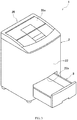
- Fig. 3 is a perspective diagram illustrating the washing machine and illustrates a condition that the drawer 8 is drawn forwards.
- the lower portion of the wall surface 22 at the front side of the washing machine 1 is provided with a rectangular opening 22a which is longer in a transverse direction, and the inner side of the opening is provided with the drawer 8. Therefore, the space below the washing tub unit 4 (referring to Fig. 2 ) can be effectively utilized, thereby further narrowing the useless space.
- the drawer 8 is used as the accommodating space for detergents, bleaching agents and softening agents necessary for washing as well as utensils such as washing nets and the like, so that a peripheral environment of the washing machine in a tendency of disorder can be easily sorted and arranged, and the usability is further improved.
- the accommodating portion 8 is configured as the drawer, and the accommodating portion can also be configured as a storage shelf with an opening and closing door.
- each portion of the washing machine 1 is not limited to the above solution and can be appropriately changed.
Landscapes
- Engineering & Computer Science (AREA)
- Textile Engineering (AREA)
- Main Body Construction Of Washing Machines And Laundry Dryers (AREA)
Abstract
Description
- The present invention relates to a washing machine capable of suppressing vibration and noise.
- In the past, in an ordinary known washing machine, a bottomed quasi-cylindrical outer tub is supported inside a box-shaped housing and a washing and dewatering tub as an inner tub is rotatably supported at an inner side of the outer tub (for example, referring to patent literature 1).
-
Fig. 4 is a longitudinal section view schematically illustrating an example of anordinary washing machine 101. - An
outer tub 105 and aninner tub 106 are coaxially configured in an inner space Sp of ahousing 2, and abottom plate 161 of theinner tub 106 is provided with anagitator 63. Furthermore, a lower side of abottom plate 151 of theouter tub 105 is provided with adriving mechanism 107 capable of selectively causing theinner tub 106 and theagitator 63 to rotate. - A
washing tub unit 104 is formed by theouter tub 105, theinner tub 106 and thedriving mechanism 107, and thewashing tub unit 104 is suspended and supported inside thehousing 2 throughhanger bars 103. Eachhanger bar 103 is configured obliquely at a specified angle θ, abase end 103A side is mounted at a suspending andfixing portion 25 arranged near anupper end 24 of thehousing 2; and atop end 103B side is mounted at a suspended and supporting portion arranged at a lower portion of acircumferential wall 152 of theouter tub 105 via adamping mechanism 31. Thus, thewashing tub unit 104 is elastically supported. Thus, excessive vibration caused by the rotation of theinner tub 106 and theagitator 63 in a washing or dewatering process can be inhibited. - Herein, width and depth dimensions of a place for arranging the
above washing machine 101 are limited by a waterproof plate and a house layout in a family. That is, the arrangement area of thewashing machine 101 shall not be too big. Furthermore, since thewashing machine 101 is set to be capable of washing multiple washings, the washing capacity is designed to be big as far as possible, so that the washing machine becomes lengthwise. - Furthermore, the
washing tub unit 104 which is also designed to be lengthwise like thehousing 2 exists from a position near theupper end 24 to a position near abottom surface 21 in a manner of occupying a majority of internal space Sp of thehousing 2. Since thewashing tub unit 104 is provided with thedriving mechanism 107 having a weight at thebottom plate 151 forming theouter tub 105, a center-of-gravity position Pc is located below the center. Therefore, a height Hc0 of the center-of-gravity position Pc0 of thewashing tub unit 104 is 30% of a height Hu from an arrangement surface F to theupper end 24 of thehousing 2. - Furthermore, in order to effectively suppress the swinging rotation of the
washing tub unit 104, thehanger bar 103 is preferably mounted at a position of a generally same height as the center-of-gravity Pc0 of thewashing tub unit 104. Therefore, the above suspended and supportingportion 53 is arranged at the lower portion of thecircumferential wall 152 of theouter tub 105. Therefore, a distance Ls0 from the suspending and fixingportion 25 forming a supporting point for installing thehanger bar 103 to a supporting point of the suspended and supporting portion is lengthened. - Patent literature 1: Japanese Laid-Open Patent Publication No.
2011-240041 - As described above, in the existing washing machine, since the center-of-gravity position of the washing tub unit is low, but the distance between the supporting points for suspending and supporting the washing tub unit is long, the swinging of the washing tub unit is increased along with the rotation of the inner tub and the agitator, causing a tendency that the vibration and the noise are increased. In addition, in order to prevent the washing tub unit from contacting the housing during swinging rotation, a gap is necessary to set between the circumferential wall of the outer tub and the housing, and the gap becomes a useless space, so that the washing capacity is limited.
- The purpose of the present invention is to effectively solve such problem and specifically to provide a washing machine capable of effectively suppressing vibration and noise of a washing tub unit and capable of reducing a gap between a circumferential wall of an outer tub and a housing so as to reduce a useless space.
- In order to achieve related purposes, the present invention adopts the following solution.
- Namely, a washing machine of the present invention includes a housing presented in a box shape and having an internal space opened upward; and a washing tub unit suspended and supported in the internal space through a hanger bar, wherein the washing tub unit has: an outer tub presented in a bottomed quasi-cylindrical shape; an inner tub presented in a bottomed quasi-cylindrical shape, coaxially configured inside the outer tub and rotatably supported by the outer tub; and a driving mechanism arranged at a lower end of the outer tub and configured to drive the inner tub to rotate; a base end side of the hanger bar is mounted near an upper end of the housing, a top end side is mounted at a lower portion of the outer tub, and a center of gravity of the washing tub unit is set at a position higher than a vertical height center of the housing.
- Furthermore, the hanger bar in the present invention are preferably mounted at a predetermined angle; the top end side is mounted at a suspended and supporting portion of the lower portion of a circumferential wall of the outer tub; and the suspended and supported portion is set at a position higher than a vertical height center of the housing.
- Furthermore, in the present invention, preferably, the driving mechanism selectively drives the inner tub and an agitator arranged at a bottom of the inner tub by transferring a rotating force of a motor, and a depth of the inner tub is set to be in a range of 50% to 70% of a diameter of the inner tub.
- Moreover, in the present invention, preferably, an accommodating portion is arranged below the washing tub unit.
- Further, the accommodating portion is preferably a drawer in the present invention.
- According to the present invention described above, since the washing tub unit is suspended and supported by from the upper end of the housing with the hanger bar as a supporting point, and the center of gravity is set at the position higher than the vertical height center of the housing, the swinging of the inner tub when the inner tub is driven by the driving mechanism to rotate is reduced, thereby reducing the vibration and noise. In addition, since the swinging rotation is reduced, correspondingly a gap between the circumferential wall of the outer tub and the housing can be narrowed, thereby reducing a useless space. Therefore, the washing capacity can be increased by correspondingly enlarging the diameters of the outer tub and the inner tub forming the washing tub unit.
- Furthermore, according to the present invention in which the suspended and supporting portion where the top end side of the hanger bar is mounted is located at the position higher than the vertical height center of the housing, in the case that the dimension of the housing and the installation position of the hanger bars on the housing are set to be same as a conventional case, a distance between the supporting points supporting the washing tub unit through the hanger bars is reduced. Therefore, the swinging of the washing tub unit can be further reduced, and the vibration and noise can be further reduced. Furthermore, since the hanger bars are installed at the specified angle, and the distance between the supporting points is shortened, compared with the traditional washing machine, the circumferential wall of the outer tub can be disposed in an outer diameter direction, thereby reducing the useless space. Furthermore, by reducing the vibration, the gap between the outer tub and the housing and the gap between the outer tub and the inner tub are also allowed to be reduced, so that the diameters of the outer tub and the inner tub can be increased, and the washing capacity can be increased.
- Furthermore, according to the present invention in which the depth of the inner tub is set to be in a range of 50% to 70% of the diameter, since the obliquity of the inner tub relative to the outer tub can be reduced without damaging the washing performance of the washing machine, the gap between the outer tub and the inner tub can be reduced, the washing capacity is further increased, and the amount of useless water (i.e. dead water) injected between the outer tub and the inner tub when in washing can be reduced. In addition, in a case of adopting the diameter the same as the traditional washing machine, since the depth of the inner tub is reduced, the washings become easy to take out. Furthermore, since a distance among the washings, water and agitator at the upper portion of the inner tub is reduced, and a stirring force generated by the agitator is easy to transfer, thereby reducing the load of a motor, and reducing manufacturing cost and energy consumption.
- Furthermore, according to the present invention in which the accommodating portion is arranged below the washing tub unit, a space below the washing tub unit can be effectively utilized, thereby further improving the usability.
- Particularly, according to the present invention in which the accommodating portion is the drawer, the accommodating portion can be used as an accommodating space of detergents, softening agents, or utensils related to the washing and the like, thereby further improving the usability.
-
-
Fig. 1 is a longitudinal section view illustrating a washing machine of an embodiment of the present invention. -
Fig. 2 is a longitudinal section view schematically illustrating the same washing machine. -
Fig. 3 is a perspective view illustrating the same washing machine. -
Fig. 4 is a longitudinal section view schematically illustrating an example of an existing washing machine. -
- 1, 101: washing machine
- 2: housing
- 3, 103: hanger bar
- 3A, 103A: base end (of hanger bar)
- 3B, 103B: top end (of hanger bar)
- 4, 104: washing tub unit
- 5, 105: outer tub
- 6, 106: inner tub
- 7: driving mechanism
- 8: drawer (accommodating portion)
- 24: upper end (of housing)
- 51, 151: bottom plate
- 52, 152: circumferential wall
- 53: suspended and supporting portion
- 61, 161: bottom plate
- 62, 162: circumferential wall
- 63: agitator
- 72, 172: motor
- 73, 173: power distribution unit
- Dp0, Dp1: depth (of inner tub)
- Hb: height center of housing
- Hc0, Hc1: height of center of gravity (of washing tub unit)
- Hu: height of housing
- Pc0, Pc1: center of gravity (of washing tub unit)
- Sp: internal space
- θ: angle (of hanger bar)
- Embodiments of the present invention are described below with reference to drawings.
-
Fig. 1 is a longitudinal section view illustrating awashing machine 1 of embodiments of the present invention. Thewashing machine 1 has a substantially quadrangular shape in top view, andFig. 1 illustrates a state that thewashing machine 1 is sectioned at a position of a diagonal line. Furthermore,Fig. 1 is a diagram illustrating a general structure of thewashing machine 1 and omitting portions unrelated to the present invention. It shall be noted that the same reference numerals are given to the portion inFig. 1 same as that in the existingwashing machine 101 shown inFig. 4 . - The
washing machine 1 of the present embodiment shown inFig. 1 is configured as a called vertical type washing machine and has ahousing 2 and awashing tub unit 4 suspended and supported inside thehousing 2 through hanger bars 3. In addition, thewashing tub unit 4 has a bottomed quasi-cylindricalouter tub 5, a bottomed quasi-cylindricalinner tub 6 coaxially configured inside the outer tub, and a driving mechanism arranged at a bottom of theouter tub 5. - The
housing 2 is formed by a substantiallyrectangular bottom surface 21 and fourwall surfaces 22 erecting from thebottom surface 21 and is formed into a box shape having an internal space Sp opened upward. Moreover, four corners of thebottom surface 21 havefeet 23. The vertical height of thehousing 2 of the present embodiment refers to a height including thefeet 23 and is defined as a height from an arrangement surface F to anupper end 24 of thehousing 2. Four corners near theupper end 24 of thehousing 2 are provided with hook-shaped suspending and fixingportions 25, and the suspending and fixingportions 25 suspendbase end 3A sides of the hanger bars 3 so as to function as supporting points for hanging the hanger bars 3. - The upper portion of the
housing 2 is provided with acover 26 integrated with an operation panel, one portion of thecover 26 is configured as an opening andclosing cover 26a, as shown inFig. 2 , and the internal space Sp can be opened and closed by changing the opening and closing cover to be in an open state PO and a closed state PC. - Returning to
Fig. 1 , theouter tub 5 forming thewashing tub unit 4 is a bottomed quasi-cylindrical member having a substantiallycircular bottom plate 51 in top view for forming the bottom and acircumferential wall 52 erecting from an edge portion of thebottom plate 51. Hook-shaped suspended and supportingportions 53 are substantially uniformly and integrally configured at four portions of the lower portion of thecircumferential wall 52 in top view. The suspended and supportingportions 53 can be mounted attop end 3B sides of the hanger bars 3. - The
inner tub 6 is configured as a so-called washing and dewatering drum and formed into a bottomed quasi-cylindrical shape having a substantiallycircular bottom plate 61 in top view for forming the bottom and acircumferential wall 62 erecting from an edge portion of thebottom plate 61. Theinner tub 6 is configured inside theouter tub 5 coaxially with theouter tub 5, and rotatably suspended and supported by theouter tub 5 through thedriving mechanism 7. Thebottom plate 61 and thecircumferential wall 62 are provided with a plurality of water through holes not shown, and water in theinner tub 6 can be discharged through the water through holes. Furthermore, anagitator 63 generally called an impeller is coaxially arranged right above thebottom plate 61 of theinner tub 6. - The
driving mechanism 7 includes abasal plate member 71 installed at the lower surface of abottom plate 51 of theouter tub 5, amotor 72 installed at thebasal plate member 71, and apower distribution unit 73 including a clutch. Themotor 72 and thepower distribution unit 73 respectively have abelt pulley 72a and abelt pulley 73a; and the peripheries of the belt pulleys 72a and 73a are wounded with anannular transmission belt 74, so that the power can be mutually transferred. - The
power distribution unit 73 has twooutput shafts first output shaft 75 at the inner side is connected to the center of theabove agitator 63, and thesecond output shaft 76 is connected to thebottom plate 61 of theinner tub 6. Thepower distribution unit 73 can selectively switch an output target of a driving force inputted from themotor 72 through thebelt pulley 73a only to thefirst output shaft 75 or to both thefirst output shaft 75 and thesecond output shaft 76 according to an external instruction. Therefore, thewashing machine 1 can only enable theagitator 63 to rotate when in washing, and enables theinner tub 6 and theagitator 63 to rotate integrally when in dewatering. - Four
hanger bars 3 are configured correspondingly to four corners of thehousing 2. Eachhanger bar 3 is slightly obliquely configured in such a manner that top ends 3B are close to each other, and the base ends 3A are suspended and fixed at the suspending and fixingportions 25 of thehousing 2. Moreover, thetop end 3B is provided with a dampingmechanism 31 including aspiral spring 31A serving as an elastic member, and theupper end 31A of the dampingmechanism 31 is suspended and fixed at the suspended and supportingportion 53 arranged at theouter tub 5. Thus, thewashing tub unit 4 including theouter tub 5 is suspended and supported through four hanger bars 3. -
Fig. 2 is a longitudinal section view schematically illustrating thewashing machine 1. InFig. 2 , the same reference numerals are given to portions same as those inFig. 1 . Referring toFig. 4 andFig. 2 , a dimensional relation of various portions is described below in detail. - Firstly, a height Hu of the
housing 2 is defined as a dimension in the vertical direction from the arrangement surface F to theupper end 24 of thehousing 2. In the present embodiment, an overall dimension of thehousing 2 is set to be substantially same as that of the existing ordinary washing machine, and the height Hu of theshell 2 is set to be about 770mm which is the same as the housing of the existing washing machine. - Moreover, the
bottom plate 61 of theinner tub 6 is arranged at a position higher than the existing washing machine, and the distance from theupper end 24 of thehousing 2 to thebottom plate 61 is configured to be short. - Herein, the depth Dp1 of the
inner tub 6 is defined as a dimension in the vertical direction from theupper end 24 of thehousing 2 to the lowermost portion of the upper surface of thebottom plate 61 of theinner tub 6, and the diameter Di1 of theinner tub 6 is defined as a maximum diameter at an inner surface of thecircumferential wall 62 of theinner tub 6. In the existing ordinary washing machine 101 (referring toFig. 4 ), in the case that the depth Dp0 and the diameter Di0 of theinner tub 106 are defined same as above, generally the depth Dp0 of theinner tub 106 is about 110% of the diameter Di0 and is longer in a lengthwise direction. - Relative to this, in the
washing machine 1 of the present embodiment, the depth Dp1 of theinner tub 6 is set as about 60% of the diameter Di1 and about half of the depth of the inner tub of the existing washing machine. Therefore, the washings can be easily taken in and out of theinner tub 6. Furthermore, since the height Hu of thehousing 2 is same as that of the housing of the existing washing machine, theupper end 24 may not become too low and people do not need to bend down to take in and out the washings. - Furthermore, since the
inner tub 6 is connected with thesecond output shaft 76, a height from the supportedbottom plate 61 to theupper end 64 is reduced. Therefore, even in the case of taking the washings to a limit position of theupper end 64, the washings may also be imbalanced when in rotation, and the torque acting in a tilting direction of theinner tub 6 is also reduced. Therefore, relative displacement between theouter tub 5 and theinner tub 6 can be reduced, so that the gap Ci1 between thecircumferential walls outer tub 5 andinner tub 6 is smaller than the gap Ci0 between thecircumferential walls outer tub 105 and theinner tub 106 of the existing washing machine. Specifically, the gap Ci1 is set as about 80% of the existing gap CiO. Thus, the useless space can be further reduced; and moreover, useless water, i.e. dead water, entering the gap between theouter tub 5 and theinner tub 6 when in washing can also be reduced. - Furthermore, in the case that the stirring force generated by the
agitator 63 needs to be transferred to theupper end 64 of theinner tub 6 when in washing, since the height to theupper end 64 is reduced, the stirring force can be set to be relatively small. Therefore, the capacity of themotor 72 can be set to be smaller than that of the existingmotor 172; and moreover, the load resistance performance of thepower distribution unit 73 is set to be smaller than that of the existingpower distribution unit 173, so that the miniaturization and cost reduction of thedriving mechanism 7 can be realized. Furthermore, the electric power consumption generated by themotor 72 can also be reduced, thereby reducing the operation cost. - Furthermore, as described above, when the
bottom plate 61 of theinner tub 6 is set at a higher position, thebottom plate 51 of theouter tub 5 and thedriving mechanism 7 mounted at the side of the lower surface side are also set at higher positions. Therefore, the integral center-of-gravity position Pc of thewashing tub unit 4 is also set at a higher position. - Herein, the height Hc1 of the center Pc1 of the
washing tub unit 4 is defined as a dimension in the vertical direction from the arrangement surface F to the center of the gravity Pc. In the existing ordinary washing machine 101 (referring toFig. 4 ), in the case that the height Hc0 of the center of gravity Pc0 of thewashing tub unit 104 is defined same as above, generally the height Hc0 of the center of gravity Pc0 is about 40% of the height Hu of thehousing 2. - Relative to this, in the
washing machine 1 of the present embodiment, the height Hc1 of the center of gravity Pc1 of thewashing tub unit 4 is greater than 50% of the height Hu of thehousing 2. That is, in the case that a half position of the height Hu of thehousing 2 is defined as a height center Hb in the vertical direction of thehousing 2, the center of gravity Pc1 of thewashing tub unit 4 is higher than the position of the height center Hb. - Therefore, in the case that the
agitator 63 and theinner tub 6 are driven by thedriving mechanism 7 to rotate, and particularly during dewatering operation that theagitator 63 and theinner tub 6 are integrally driven to rotate at high speed, even in the case of swinging rotation of thewashing tub unit 4, since theupper end 24 of thehousing 2 having the supporting points for suspending and supporting the hanger bars 2 is close to the center-of-gravity position Pc1, the swinging is reduced and the overall vibration and noise are reduced. - Furthermore, in the
washing machine 1 of the present embodiment, as thebottom plate 51 of theouter tub 5 and the center-of-gravity position Pc1 of thewashing tub unit 4 are set to be higher, the position of the suspended and supportingportion 53 for installing thetop end 3B side of thehanger bar 3 is also higher than the position of the suspended and supporting portion of the existing washing machine. Specifically, the distance Ls1 from the suspending and fixingportion 25 for installing thebase end 3A of thehanger bar 3 to the supporting point of the suspended and supportingportion 53 for installing thetop end 3B side is reduced to be about 60% of the distance Ls0 between the supporting points of the existing washing machine. Therefore, the swinging of thewashing tub unit 4 can be further reduced, thereby further reducing the vibration and noise. - Furthermore, the length La1 of the
hanger bar 3 can also be shortened by shortening the distance Ls1 between the supporting points. Specifically, in the case of utilizing the damping mechanism same as before, the length La1 of thehanger bar 3 is changed to be about 70% of the length La0 of thehanger bar 103 of the existing washing machine. Therefore, an effect for reducing the manufacturing cost of parts and further narrowing the useless space in thehousing 2 can be achieved. - Furthermore, each
hanger bar 3 is inclinedly mounted at a predetermined angle θ such that thetop end 3B sides are close to each other. Thus, a pulling force is applied to four corners of thewashing tub unit 4 through eachhanger bar 3, so that the stability of the central position of thehousing 2 in top view can be improved. Specifically, the angle θ is also set to be about 9° same as that of the existing washing machine. - In the case that the hanger bars 3 are inclined at the specified angle θ, corresponding to the distance Ls1 between the supporting points for installing the hanger bars 3, a gap Co1 between the
wall surface 22 of thehousing 2 and thecircumferential wall 52 of theouter tub 5 needs to be set. In the present embodiment, as described above, the distance Ls1 between the supporting points is set to be about 60% of the distance Ls0 between the supporting points of the existing washing machine, and correspondingly thecircumferential wall 52 of theouter tub 5 is disposed in the outer diameter direction, thereby narrowing the useless space, and the gap Co1 is smaller than the gap Co0 of the existing washing machine. Specifically, the gap Co1 is set to be about 80% of the gap Co0 of the existing washing machine, and correspondingly the diameter of theouter tub 5 is increased. - Moreover, except that the gap Ci1 between the
outer tub 5 and theinner tub 6 is set to be smaller than the gap Ci0 of the existing washing machine, by setting the gap Co1 between thewall surface 22 of thehousing 2 and thecircumferential wall 52 of theouter tub 5 to be smaller than the gap Co0 of the existing washing machine, the diameter Di0 of theinner tub 5 is increased correspondingly. Specifically, the diameter Di0 of theinner tub 5 is set to be about 115% of the diameter Di0 of theinner tub 105 of the existing washing machine, and the space in the radius direction is increased, thereby increasing the washing capacity. Therefore, the washing capacity is not reduced proportionally to the reduction of the depth Dp1, but a sufficient washing capacity can be ensured. - Furthermore, for the
washing machine 1 of the present embodiment as described above, thewashing tub unit 4 is integrally installed at the top, so that the lower side of the internal space Sp can be open to a large extent. Therefore, the space can be used to install thedrawer 8 as the accommodating portion. -
Fig. 3 is a perspective diagram illustrating the washing machine and illustrates a condition that thedrawer 8 is drawn forwards. The lower portion of thewall surface 22 at the front side of thewashing machine 1 is provided with arectangular opening 22a which is longer in a transverse direction, and the inner side of the opening is provided with thedrawer 8. Therefore, the space below the washing tub unit 4 (referring toFig. 2 ) can be effectively utilized, thereby further narrowing the useless space. Furthermore, thedrawer 8 is used as the accommodating space for detergents, bleaching agents and softening agents necessary for washing as well as utensils such as washing nets and the like, so that a peripheral environment of the washing machine in a tendency of disorder can be easily sorted and arranged, and the usability is further improved. - It shall be noted that a specific structure of each portion is not limited to the above embodiments.
- For example, in the above embodiments, the
accommodating portion 8 is configured as the drawer, and the accommodating portion can also be configured as a storage shelf with an opening and closing door. - Furthermore, various apparatuses for increasing additional functions can also be properly included and can be integrally configured to substitute the
accommodating portion 8. - Furthermore, the dimension of each portion of the
washing machine 1 is not limited to the above solution and can be appropriately changed. - Various variations can be made to other structures without departing from technical spirit of the present invention.
Claims (5)
- A washing machine, comprising:a box-shaped housing having an internal space opened upward; anda washing tub unit suspended and supported in the internal space through a hanger bar,wherein the washing tub unit comprises an outer tub presented in a bottomed quasi-cylindrical shape; an inner tub presented in a bottomed quasi-cylindrical shape, coaxially configured inside the outer tub and rotatably supported by the outer tub; and a driving mechanism arranged at a lower end of the outer tub and configured to drive the inner tub to rotate;a base end side of the hanger bar is mounted in the vicinity of an upper end of the housing, and a top end side is installed at a lower portion of the outer tub; anda center of gravity of the washing tub unit is set at a position higher than a height center in a vertical direction of the housing.
- The washing machine according to claim 1, whereinthe hanger bar is mounted at a predetermined angle, and the top end side is mounted at a suspended and supporting portion arranged at the lower portion of a circumferential wall of the outer tub; andthe suspended and supporting portion is set at a position higher than the height center in the vertical direction of the housing.
- The washing machine according to claim 2, whereinthe driving mechanism selectively drives the inner tub and an agitator arranged at a bottom of the inner tub by transferring a rotating force of a motor; anda depth of the inner tub is set in a range of 50% to 70% of a diameter of the inner tub.
- The washing machine according to claim 2 or 3, wherein an accommodating portion is arranged below the washing tub unit.
- The washing machine according to claim 4, wherein the accommodating portion is a drawer.
Applications Claiming Priority (2)
| Application Number | Priority Date | Filing Date | Title |
|---|---|---|---|
| JP2014259457A JP6502087B2 (en) | 2014-12-22 | 2014-12-22 | How to design a washing machine |
| PCT/CN2015/097812 WO2016101839A1 (en) | 2014-12-22 | 2015-12-18 | Washing machine |
Publications (2)
| Publication Number | Publication Date |
|---|---|
| EP3239380A1 true EP3239380A1 (en) | 2017-11-01 |
| EP3239380A4 EP3239380A4 (en) | 2018-08-29 |
Family
ID=56149255
Family Applications (1)
| Application Number | Title | Priority Date | Filing Date |
|---|---|---|---|
| EP15871907.0A Withdrawn EP3239380A4 (en) | 2014-12-22 | 2015-12-18 | Washing machine |
Country Status (6)
| Country | Link |
|---|---|
| US (1) | US20180112344A1 (en) |
| EP (1) | EP3239380A4 (en) |
| JP (1) | JP6502087B2 (en) |
| KR (1) | KR20170098905A (en) |
| CN (1) | CN107109748B (en) |
| WO (1) | WO2016101839A1 (en) |
Families Citing this family (4)
| Publication number | Priority date | Publication date | Assignee | Title |
|---|---|---|---|---|
| JP2018042681A (en) * | 2016-09-13 | 2018-03-22 | 青島海爾洗衣机有限公司QingDao Haier Washing Machine Co.,Ltd. | Washing machine |
| CN112111926B (en) * | 2019-06-21 | 2023-09-08 | 青岛海尔洗衣机有限公司 | Washing tubs and washing machines |
| CN113249921A (en) * | 2020-02-11 | 2021-08-13 | 青岛海尔洗衣机有限公司 | Washing machine |
| CN111411482B (en) * | 2020-02-28 | 2023-10-24 | 重庆海尔洗衣机有限公司 | Clothes processing equipment and control method |
Family Cites Families (23)
| Publication number | Priority date | Publication date | Assignee | Title |
|---|---|---|---|---|
| FR1180688A (en) * | 1957-06-07 | 1959-06-08 | Simplified and improved semi-automatic washing machine | |
| JPS531193Y2 (en) * | 1973-04-20 | 1978-01-13 | ||
| JPS5212510B2 (en) * | 1973-09-07 | 1977-04-07 | ||
| JPS5110667A (en) * | 1974-07-17 | 1976-01-28 | Matsushita Electric Industrial Co Ltd | Enshindatsusuiki |
| JPS5628798A (en) * | 1979-08-16 | 1981-03-20 | Matsushita Electric Industrial Co Ltd | Driving device for hydroextracting washing machine |
| JPS60171077A (en) * | 1984-02-14 | 1985-09-04 | 松下電器産業株式会社 | Liquid balancer of washer |
| JPS6315998A (en) * | 1986-07-04 | 1988-01-23 | 松下電器産業株式会社 | washing machine |
| JPH03275098A (en) * | 1990-03-26 | 1991-12-05 | Nobuhiro Takao | Washing machine with laundry basket |
| JPH06304381A (en) * | 1993-04-23 | 1994-11-01 | Tokai Rubber Ind Ltd | Fully automatic washing machine and vibration preventer therefor |
| JPH07227495A (en) * | 1994-02-18 | 1995-08-29 | Sharp Corp | Electric washing machine |
| CN2265389Y (en) * | 1996-06-14 | 1997-10-22 | 青岛海尔洗衣机有限总公司 | Top hanging dehydrator |
| JPH11146995A (en) * | 1997-11-16 | 1999-06-02 | Masahiro Murakawa | Washing machine with shelves, telescopic containers and storage |
| CN1250800C (en) * | 1998-04-10 | 2006-04-12 | 松下电器产业株式会社 | Washing machine |
| KR20000001810U (en) * | 1998-06-30 | 2000-01-25 | 전주범 | Suspension of washing machine |
| JP2001129296A (en) * | 1999-11-04 | 2001-05-15 | Hitachi Ltd | Electric washing machine |
| CN2612705Y (en) * | 2002-11-16 | 2004-04-21 | 海尔集团公司 | Washing machine with drawer |
| JP2004180883A (en) * | 2002-12-03 | 2004-07-02 | Tetsuo Takeuchi | Drum type washing/drying machine with housing function |
| US7313933B2 (en) * | 2004-02-18 | 2008-01-01 | Whirlpool Corporation | Laundry appliance utility shelf |
| JP2005304715A (en) * | 2004-04-20 | 2005-11-04 | Hitachi Ltd | Electric washing machine |
| CN1978739B (en) * | 2005-12-05 | 2010-05-12 | 海尔集团公司 | Suspension type double wave wheel washing machine outer tub hanging device |
| ATE533880T1 (en) * | 2008-04-30 | 2011-12-15 | Lg Electronics Inc | WASHING MACHINE |
| KR101482108B1 (en) * | 2008-05-23 | 2015-01-13 | 엘지전자 주식회사 | Washing machine |
| WO2010107277A1 (en) * | 2009-03-20 | 2010-09-23 | 엘지전자 주식회사 | Laundry processing apparatus |
-
2014
- 2014-12-22 JP JP2014259457A patent/JP6502087B2/en active Active
-
2015
- 2015-12-18 KR KR1020177020415A patent/KR20170098905A/en not_active Ceased
- 2015-12-18 WO PCT/CN2015/097812 patent/WO2016101839A1/en not_active Ceased
- 2015-12-18 CN CN201580070382.8A patent/CN107109748B/en not_active Expired - Fee Related
- 2015-12-18 EP EP15871907.0A patent/EP3239380A4/en not_active Withdrawn
- 2015-12-18 US US15/538,079 patent/US20180112344A1/en not_active Abandoned
Also Published As
| Publication number | Publication date |
|---|---|
| US20180112344A1 (en) | 2018-04-26 |
| WO2016101839A1 (en) | 2016-06-30 |
| KR20170098905A (en) | 2017-08-30 |
| JP2016116789A (en) | 2016-06-30 |
| EP3239380A4 (en) | 2018-08-29 |
| CN107109748B (en) | 2020-09-01 |
| CN107109748A (en) | 2017-08-29 |
| JP6502087B2 (en) | 2019-04-17 |
Similar Documents
| Publication | Publication Date | Title |
|---|---|---|
| US9951452B2 (en) | Drum-type washing machine | |
| CA2898938C (en) | Laundry treatment apparatus with suspension assembly having elastic member on outer circumferential surface of support member | |
| CA2898942C (en) | Laundry treatment apparatus with drum connected to motor shaft | |
| US20180112344A1 (en) | Washing machine | |
| EP2476790A1 (en) | Washing Machine and Pulsator Thereof | |
| KR102009186B1 (en) | Drum washing machine | |
| RU2617377C2 (en) | Balancer and washing machine with such balancer | |
| US20120090362A1 (en) | Laundry machine | |
| US9951453B2 (en) | Washing machine and method of manufacturing washing tub being provided therein | |
| TWI592539B (en) | Washing machine | |
| CN105229215A (en) | Roller washing machine | |
| JP2016049371A (en) | Drum washing machine | |
| CN107287825A (en) | Vibration damper and the washing machine including vibration damper | |
| RU2497991C2 (en) | Washing machine | |
| KR102557928B1 (en) | Lifter and washing machine having the same | |
| US20190330782A1 (en) | Washing machine | |
| EP2465990B1 (en) | Washing machine | |
| JP2017086686A (en) | Washing machine | |
| JP2014004002A (en) | Drum type washing machine | |
| CN107075772B (en) | Top-opening washing machine | |
| EP3339494A1 (en) | Washing machine | |
| CN106103827B (en) | Washing machine | |
| CN112111926A (en) | Washing tubs and washing machines | |
| JP2019187455A (en) | Washing machine | |
| KR20120073574A (en) | Lifter for drum type washing machine |
Legal Events
| Date | Code | Title | Description |
|---|---|---|---|
| PUAI | Public reference made under article 153(3) epc to a published international application that has entered the european phase |
Free format text: ORIGINAL CODE: 0009012 |
|
| 17P | Request for examination filed |
Effective date: 20170719 |
|
| AK | Designated contracting states |
Kind code of ref document: A1 Designated state(s): AL AT BE BG CH CY CZ DE DK EE ES FI FR GB GR HR HU IE IS IT LI LT LU LV MC MK MT NL NO PL PT RO RS SE SI SK SM TR |
|
| AX | Request for extension of the european patent |
Extension state: BA ME |
|
| DAV | Request for validation of the european patent (deleted) | ||
| DAX | Request for extension of the european patent (deleted) | ||
| A4 | Supplementary search report drawn up and despatched |
Effective date: 20180731 |
|
| RIC1 | Information provided on ipc code assigned before grant |
Ipc: D06F 37/24 20060101AFI20180720BHEP Ipc: D06F 39/12 20060101ALN20180720BHEP Ipc: D06F 37/12 20060101ALN20180720BHEP |
|
| STAA | Information on the status of an ep patent application or granted ep patent |
Free format text: STATUS: THE APPLICATION HAS BEEN WITHDRAWN |
|
| 18W | Application withdrawn |
Effective date: 20190206 |