EP3239000A1 - Support frame connectable to a vehicle, in particular for the transport of bicycles and motorcycles, and vehicle provided with brackets for coupling such support frame - Google Patents
Support frame connectable to a vehicle, in particular for the transport of bicycles and motorcycles, and vehicle provided with brackets for coupling such support frame Download PDFInfo
- Publication number
- EP3239000A1 EP3239000A1 EP16425036.7A EP16425036A EP3239000A1 EP 3239000 A1 EP3239000 A1 EP 3239000A1 EP 16425036 A EP16425036 A EP 16425036A EP 3239000 A1 EP3239000 A1 EP 3239000A1
- Authority
- EP
- European Patent Office
- Prior art keywords
- support frame
- vehicle
- hinge
- axis
- brackets
- Prior art date
- Legal status (The legal status is an assumption and is not a legal conclusion. Google has not performed a legal analysis and makes no representation as to the accuracy of the status listed.)
- Granted
Links
Images

Classifications
-
- B—PERFORMING OPERATIONS; TRANSPORTING
- B60—VEHICLES IN GENERAL
- B60R—VEHICLES, VEHICLE FITTINGS, OR VEHICLE PARTS, NOT OTHERWISE PROVIDED FOR
- B60R9/00—Supplementary fittings on vehicle exterior for carrying loads, e.g. luggage, sports gear or the like
- B60R9/08—Supplementary fittings on vehicle exterior for carrying loads, e.g. luggage, sports gear or the like specially adapted for sports gear
- B60R9/10—Supplementary fittings on vehicle exterior for carrying loads, e.g. luggage, sports gear or the like specially adapted for sports gear for cycles
Definitions
- the present invention relates to a support frame configured to be coupled to a vehicle to carry additional loads besides those that may be contained in a trunk or in a rear load compartment of the vehicle.
- the present invention makes explicit reference to the transport of bicycles and motorcycles, without thereby losing generality.
- the known support frames are not completely satisfactory, as they are relatively bulky and, in general, their presence makes impossible the opening of the rear doors, even when the bicycle or motorcycle is not on the support frame.
- the coupling methods provided for securing the frame to the vehicle body generally do not allow to quickly fasten and unfasten the additional frame and, at the same time, to support a heavy load.
- the known solutions that can be quickly fastened and unfastened, in general only allow to carry a load with a relatively low weight, for example a single bicycle.
- the object of the present invention is to provide a support frame connectable to a vehicle, in particular for the transport of bicycles and motorcycles, solving in a simple and inexpensive way the drawbacks set forth above.
- the present invention provides a support frame connectable to a vehicle, in particular for the transport of bicycles and motorcycles, as defined in claim 1.
- the present invention also provides a vehicle provided with brackets for coupling a support frame, as defined in claim 11.
- the reference number 1 indicates a support frame, which is configured to be fixedly coupled to a vehicle 2 (partially shown) to carry an additional load.
- the vehicle 2 has a rear load compartment or a luggage compartment 3, which is provided with a rear access opening 4, delimited on the sides by two uprights 5.
- the vehicle 2 comprises one or more movable doors 6 to open and close the opening 4; in particular, there are provided two doors 6, each hinged to a respective upright 5 about a substantially vertical axis.
- the frame 1 can also be applied to solutions provided with a rear door pivotable about a horizontal axis.
- the frame 1 is coupled to right brackets 7A and left brackets 7B, which are arranged on opposite sides of the opening 4 and of the doors 6 and are secured to the vehicle body 2, as described more in detail below.
- the frame 1 is elongated along an axis 8, which, in use, is horizontal and orthogonal to the longitudinal travel direction of the vehicle 2.
- the frame 1 is generally L-shaped, if cross-sectioned along a plane orthogonal to the axis 8.
- the frame 1 comprises a connecting structure 10 and a support structure 11, which cantileverly projects from a lower end of the structure 10 and has an upper surface 12, which defines a support plane parallel to the axis 8.
- the structure 10 cantileverly projects upward from a front end of the structure 11 and then extends transversely to the surface 12.
- the structure 10 protrudes orthogonally to the surface 12.
- the structure 10 is substantially vertical.
- the structure 11 is defined by two parallel bars 14 and the surface 12 is defined by the upper face of said bars 14.
- the frame 1 further comprises a channel 15, which is parallel to the axis 8 and is fixedly arranged on the surface 12.
- the channel 15 is configured to support and hold the wheels of a bicycle or a motorcycle (not shown) and is of a known type, so that is not described and/or shown in more detail.
- the channel 15 is hinged to one of the two bars 14 by a hinge 16 to rotate about a hinge axis parallel to the bars 14.
- the channel 15 rests on the other bar 14 and is specifically held on this latter by means of a not shown removable constraint, e.g. by means of a hook or a padlock.
- the channel 15 allows to load the motorcycle.
- two further hinges can be possibly provided at the front ends of the bars 14 to rotate the structure 11, for example upward, about an axis of rotation parallel to the axis 8.
- the structure 10 comprises two bars 18 parallel to the axis 8 and spaced apart in a direction transverse to the surface 12.
- the structure 10 further comprises an inclined bar 19, whose ends are respectively secured to the bars 18, for example by welding.
- the structure 10 further comprises two attachment members 20, which are arranged at opposite side ends of the frame 1, along the axis 8.
- the attachment members 20 are configured to be respectively coupled to the brackets 7A and 7B in fixed positions and in a releasable way.
- At least one of the side ends of the structure 10 comprises a hinge 21, defined by a hinge seat and/or by a hinge pin and having a hinge axis 22 which is orthogonal to the axis 8 and extends transversely to the surface 12, so that it is substantially vertical and/or parallel to the uprights 5.
- the hinge 21 enables a rotation of the frame 1 with respect to the vehicle body 2 about the axis 22 when the attachment member 20 of the opposite side end is disengaged from the corresponding brackets (7A or 7B). Thanks to this feature, a user can temporarily move the frame 1 toward a side of the vehicle 2 without completely removing the frame 1, and therefore can open the doors 6 and easy access the load compartment 3 in case of need.
- the hinge 21 is integrated in at least one of the attachment members 20.
- the two attachment members 20 are similar, so that both work as a hinge, thus allowing the user to decide freely whether to rotate the frame 1 toward the right side or toward the left side of the vehicle 2.
- the hinge 21 is a separate device from the attachment members 20, but in any case it is arranged at at least one of the opposite side ends of the frame 1 to allow the rotation of the structure 11 and of an intermediate part of the structure 10 about the hinge axis 22 toward the right side or toward the left side of the vehicle 2.
- each attachment member 20 preferably comprises a tubular element 24, preferably secured to the ends of the bars 18 and defining an inner seat 25, which extends along the axis 22 and leads to the top and bottom ends of the tubular element 24.
- Each attachment member 20 further comprises at least one pin 26, which is coaxial with the seat 25.
- two pins 26 are provided, each at a corresponding axial end of the seat 25.
- each pin 26 of the attachment member 20 comprises an inner portion 27 engaging the seat 25 and an axial end 28, which protrudes from the tubular element 24 to engage one of these brackets.
- the ends 28 define the hinge 21, and rotatably engage corresponding hinge seats 29 of the brackets 7 ( Figure 5 ).
- the pins 26 may be defined by latches which are completely separate and independent from the tubular elements 24 when the frame 1 is uncoupled from the vehicle 2, and which are axially inserted from the outside, through the hinge seats 29 and into the seat 25, by the user when the frame 1 is to be secured to the vehicle body 2; or the pins 26 can be defined by latches that remain coupled to the tubular elements 24 when the frame 1 is uncoupled from the vehicle 2, e.g. as provided in the variant shown in Figure 4 .
- the parts constituting the attachment member 20 are identified, where possible, by the same reference numbers used in Figure 3 .
- the pins 26 are restrained to the tubular element 24 so as to slide axially between a retracted position (not shown), where they are completely housed in the seat 25, and an extracted position, where the ends 28 axially protrude from the tubular element 24.
- the attachment member 20 further comprises a lever mechanism 30 arranged, at least in part, out of the tubular element 24, coupled to the pins 26 and operable, for example manually, to translate the pins 26 between their retracted and their extracted positions.
- the lever mechanism 30 comprises two connecting rods 31, which at one end are hinged to the portions 27 about respective pins 33, mutually parallel and orthogonal to the axis 22.
- the opposite ends of the connecting rods 31 are hinged to a control lever 35 at an end area 36 and, respectively, an intermediate area 37.
- the lever 35 comprises an end portion 38 that cantileverly extends with respect to the area 37 and is operable to rotate the lever 35 so that the pins 33 get axially closer or farther.
- the tubular element 24 has two slits 39 parallel to the axis 22 and respectively engaged by the pins 33, preferably guiding the sliding of the pins 33 parallel to the axis 22 during the operation of the lever mechanism 30.
- the lever 35 preferably has a hinging area, which is intermediate between the areas 36 and 37 and is hinged to the attachment member 20 at a central point between the slits 39.
- each side of the vehicle 2 provides only two coupling points, namely an upper constraint point and a lower constraint point.
- Bracket points or coupling points, in particular, are defined by respective brackets.
- Figure 5 shows an upper bracket 7C and a lower bracket 7D, secured to respective parts of the vehicle body.
- the brackets 7C and 7D comprise respective plates 40C, 40D on which the hinge seats 29 are formed in mutually coaxial positions.
- the distance between the plates 40C, 40D is equal to the axial height of the corresponding tubular element 24, so as not to leave a vertical clearance to the frame 1 with respect to the brackets 7.
- brackets 7C and 7D are secured to the corresponding parts of the vehicle body only by means of screws or bolts 41.
- the upper constraint point and the lower constraint point are defined by a single bracket, namely by a single piece which is equivalent to the set of brackets 7C and 7D, so as to limit possible positioning errors of the brackets 7C and 7D (with regard to the vertical alignment, to the relative distance, to the parallelism of the plates 40C and 40D, etc... ).
- the vehicle 2 is a commercial vehicle having a rear bumper 42 arranged below the doors 6 and extending between two side structures 43, which are normally made of plastic material and are called “cantonals".
- the structures 43 are arranged on opposite sides of the doors 6.
- the bracket 7D is superimposed and secured to a metal wall 44, which is arranged below the structures 43, in a position horizontally, aligned with the rear bumper 42.
- the ends of a regular rear bumper must be possibly removed and/or modified to enable the mounting and/or the passage of the brackets 7D, aligning the hinge seats 29 along the axes 22 without altering the body structure.
- a modification of this type is relatively small and does not alter the security requirements that must meet the vehicle 2 in relation to a rear impact.
- the side ends of the rear bumper 42 are uncoupled from the structures 43 and are also secured to the plates 44.
- bracket 7C this latter is preferably superimposed and secured to a metal wall 46, being part of a fastening system 47 which secures a lower hinge of the door 6 to the corresponding upright 5.
- the proposed solution allows a rotation of the frame 1, in case of need, on a side of the vehicle 2, in order to open the doors 6 and then access the load compartment 3.
- the frame 1 can be rotated both on the right and on the left side.
- the proposed solution is relatively simple and compact, since the hinge 21 is part of the attachment members 20 that secure the frame 1 to the brackets 7.
- the proposed solution the one of Figure 4 , provides for a so-called "quick coupling" to connect the frame 1, which facilitates the operations of fastening and unfastening to the vehicle 2.
- the vehicle 2 is provided with a very simple system to secure the frame 1, namely with brackets 7 which are simply bolted to the vehicle body and may possibly be applied in a workshop, even outside of the production line.
- the frame 1 defines a product that can be chosen within a so-called "after-market accessories line”.
- the brackets 7 are minimally invasive with regard to any change to be made on the vehicle 2, are relatively scarcely bulky and do not affect the aesthetics of the vehicle 2 (when the frame 1 is not mounted, the brackets 7 are almost invisible from a close point of view).
- the ensemble formed by the frame 1 and the brackets 7 is relatively lightweight if compared to the known solutions that can support an equal load. Furthermore, the use of the channel 15 allows easily loading and securing a motorcycle for transporting it behind the doors 6. However, it is not excluded that the frame 1 may have a different configuration to transport different types of loads.
- the configuration of the elements 24 may be different from the one shown by way of example.
- sensors might be provided, possibly in connection with the vehicle on-board electronics, to detect possible anomalies, such as an abnormal coupling of the frame 1 to the brackets 7 and/or an excessive load on the frame 1, with a subsequent signalling of the anomaly to the user or driver.
- further detention systems might be provided to increase the stability of the coupling between the frame 1 and the brackets 7; for example, such fastening systems could be controlled by a closing/opening electronic signal depending on the so-called "central locking" of the vehicle 2.
Landscapes
- Engineering & Computer Science (AREA)
- Mechanical Engineering (AREA)
- Body Structure For Vehicles (AREA)
- Fittings On The Vehicle Exterior For Carrying Loads, And Devices For Holding Or Mounting Articles (AREA)
Abstract
Description
- The present invention relates to a support frame configured to be coupled to a vehicle to carry additional loads besides those that may be contained in a trunk or in a rear load compartment of the vehicle. In particular, the present invention makes explicit reference to the transport of bicycles and motorcycles, without thereby losing generality.
- On the market, there are many known solutions of bicycle racks and motorcycle racks, which are coupled to motor vehicles at a rear part of their body, i.e. behind the rear door closing the luggage compartment or the load compartment.
- The known support frames are not completely satisfactory, as they are relatively bulky and, in general, their presence makes impossible the opening of the rear doors, even when the bicycle or motorcycle is not on the support frame.
- Furthermore, in the known solutions, the coupling methods provided for securing the frame to the vehicle body generally do not allow to quickly fasten and unfasten the additional frame and, at the same time, to support a heavy load. In other words, the known solutions that can be quickly fastened and unfastened, in general, only allow to carry a load with a relatively low weight, for example a single bicycle.
- Some known solutions, then, require modifications to the motor vehicle body to allow coupling the support frame. Usually, such modifications are relevant and, therefore, require a procedure of re-homologation of the vehicle.
- The object of the present invention is to provide a support frame connectable to a vehicle, in particular for the transport of bicycles and motorcycles, solving in a simple and inexpensive way the drawbacks set forth above.
- The present invention provides a support frame connectable to a vehicle, in particular for the transport of bicycles and motorcycles, as defined in
claim 1. - The present invention also provides a vehicle provided with brackets for coupling a support frame, as defined in
claim 11. - For a better understanding of the present invention it is now described a preferred embodiment, purely by way of a non-limiting example, with reference to the accompanying drawings, in which:
-
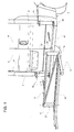
Figure 1 is a perspective of a preferred embodiment of the support frame connectable to a vehicle, in particular for the transport of bicycles and motorcycles, according to the present invention; -
Figure 2 shows, on an enlarged scale, the support frame ofFigure 1 ; -
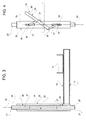
Figure 3 is a section, on an enlarged scale, of a detail of the support frame, obtained through a vertical section plane, orthogonal to the axis of the support frame; -
Figure 4 shows, in side view, a variant of the detail ofFigure 3 ; and -
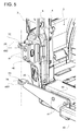
Figure 5 shows, on an enlarged scale, a detail of the vehicle visible inFigure 1 . - In
Figure 1 , thereference number 1 indicates a support frame, which is configured to be fixedly coupled to a vehicle 2 (partially shown) to carry an additional load. With reference toFigure 5 , thevehicle 2 has a rear load compartment or aluggage compartment 3, which is provided with arear access opening 4, delimited on the sides by twouprights 5. As shown inFigure 1 , thevehicle 2 comprises one or moremovable doors 6 to open and close theopening 4; in particular, there are provided twodoors 6, each hinged to a respective upright 5 about a substantially vertical axis. However, theframe 1 can also be applied to solutions provided with a rear door pivotable about a horizontal axis. - The
frame 1 is coupled toright brackets 7A andleft brackets 7B, which are arranged on opposite sides of theopening 4 and of thedoors 6 and are secured to thevehicle body 2, as described more in detail below. - With reference to
Figure 2 , theframe 1 is elongated along anaxis 8, which, in use, is horizontal and orthogonal to the longitudinal travel direction of thevehicle 2. Theframe 1 is generally L-shaped, if cross-sectioned along a plane orthogonal to theaxis 8. In particular, theframe 1 comprises a connectingstructure 10 and asupport structure 11, which cantileverly projects from a lower end of thestructure 10 and has anupper surface 12, which defines a support plane parallel to theaxis 8. - In turn, the
structure 10 cantileverly projects upward from a front end of thestructure 11 and then extends transversely to thesurface 12. Preferably, thestructure 10 protrudes orthogonally to thesurface 12. Moreover, when theframe 1 is secured to thevehicle 2, thestructure 10 is substantially vertical. - According to the shown preferred embodiment, the
structure 11 is defined by twoparallel bars 14 and thesurface 12 is defined by the upper face of saidbars 14. - Preferably, the
frame 1 further comprises achannel 15, which is parallel to theaxis 8 and is fixedly arranged on thesurface 12. Thechannel 15 is configured to support and hold the wheels of a bicycle or a motorcycle (not shown) and is of a known type, so that is not described and/or shown in more detail. - In particular, the
channel 15 is hinged to one of the twobars 14 by ahinge 16 to rotate about a hinge axis parallel to thebars 14. Thechannel 15 rests on theother bar 14 and is specifically held on this latter by means of a not shown removable constraint, e.g. by means of a hook or a padlock. - In the lowered position, the
channel 15 allows to load the motorcycle. - In case of need, for example to reduce the overall size of the
frame 1 during the transport when no motorcycle is on board, two further hinges can be possibly provided at the front ends of thebars 14 to rotate thestructure 11, for example upward, about an axis of rotation parallel to theaxis 8. - According to the shown preferred embodiment, the
structure 10 comprises twobars 18 parallel to theaxis 8 and spaced apart in a direction transverse to thesurface 12. Thestructure 10 further comprises aninclined bar 19, whose ends are respectively secured to thebars 18, for example by welding. - The
structure 10 further comprises twoattachment members 20, which are arranged at opposite side ends of theframe 1, along theaxis 8. According to an aspect of the present invention, theattachment members 20 are configured to be respectively coupled to thebrackets - According to an aspect of the present invention, at least one of the side ends of the
structure 10 comprises ahinge 21, defined by a hinge seat and/or by a hinge pin and having ahinge axis 22 which is orthogonal to theaxis 8 and extends transversely to thesurface 12, so that it is substantially vertical and/or parallel to theuprights 5. Thehinge 21 enables a rotation of theframe 1 with respect to thevehicle body 2 about theaxis 22 when theattachment member 20 of the opposite side end is disengaged from the corresponding brackets (7A or 7B). Thanks to this feature, a user can temporarily move theframe 1 toward a side of thevehicle 2 without completely removing theframe 1, and therefore can open thedoors 6 and easy access theload compartment 3 in case of need. - Preferably, as described more in detail below, the
hinge 21 is integrated in at least one of theattachment members 20. Advantageously, the twoattachment members 20 are similar, so that both work as a hinge, thus allowing the user to decide freely whether to rotate theframe 1 toward the right side or toward the left side of thevehicle 2. According to a variant not shown, thehinge 21 is a separate device from theattachment members 20, but in any case it is arranged at at least one of the opposite side ends of theframe 1 to allow the rotation of thestructure 11 and of an intermediate part of thestructure 10 about thehinge axis 22 toward the right side or toward the left side of thevehicle 2. - As shown in a simplified way in the cross-section of
Figure 3 , eachattachment member 20 preferably comprises atubular element 24, preferably secured to the ends of thebars 18 and defining aninner seat 25, which extends along theaxis 22 and leads to the top and bottom ends of thetubular element 24. Obviously, as an alternative to the one shown inFigure 3 , two axially separate seats might be provided, instead of a single throughseat 25. Eachattachment member 20 further comprises at least onepin 26, which is coaxial with theseat 25. In particular, twopins 26 are provided, each at a corresponding axial end of theseat 25. When theframe 1 is coupled to thebrackets pin 26 of theattachment member 20 comprises aninner portion 27 engaging theseat 25 and anaxial end 28, which protrudes from thetubular element 24 to engage one of these brackets. In the specific case, theends 28 define thehinge 21, and rotatably engagecorresponding hinge seats 29 of the brackets 7 (Figure 5 ). - The
pins 26 may be defined by latches which are completely separate and independent from thetubular elements 24 when theframe 1 is uncoupled from thevehicle 2, and which are axially inserted from the outside, through thehinge seats 29 and into theseat 25, by the user when theframe 1 is to be secured to thevehicle body 2; or thepins 26 can be defined by latches that remain coupled to thetubular elements 24 when theframe 1 is uncoupled from thevehicle 2, e.g. as provided in the variant shown inFigure 4 . - In
Figure 4 , the parts constituting theattachment member 20 are identified, where possible, by the same reference numbers used inFigure 3 . In this embodiment, thepins 26 are restrained to thetubular element 24 so as to slide axially between a retracted position (not shown), where they are completely housed in theseat 25, and an extracted position, where theends 28 axially protrude from thetubular element 24. Theattachment member 20 further comprises alever mechanism 30 arranged, at least in part, out of thetubular element 24, coupled to thepins 26 and operable, for example manually, to translate thepins 26 between their retracted and their extracted positions. In particular, thelever mechanism 30 comprises two connectingrods 31, which at one end are hinged to theportions 27 aboutrespective pins 33, mutually parallel and orthogonal to theaxis 22. The opposite ends of the connectingrods 31 are hinged to acontrol lever 35 at anend area 36 and, respectively, anintermediate area 37. Thelever 35 comprises an end portion 38 that cantileverly extends with respect to thearea 37 and is operable to rotate thelever 35 so that thepins 33 get axially closer or farther. - In particular, when the
lever 35 extends orthogonally to theaxis 22, thepins 26 are in their retracted position. On the contrary, when thelever 35 is parallel to theaxis 22, thepins 26 are in the extracted position. As shown inFigure 4 , furthermore, thetubular element 24 has twoslits 39 parallel to theaxis 22 and respectively engaged by thepins 33, preferably guiding the sliding of thepins 33 parallel to theaxis 22 during the operation of thelever mechanism 30. - The
lever 35 preferably has a hinging area, which is intermediate between theareas attachment member 20 at a central point between theslits 39. - With reference to
Figure 5 , the brackets 7 are relatively simply coupled to thevehicle body 2. First, each side of thevehicle 2 provides only two coupling points, namely an upper constraint point and a lower constraint point. - The constraint points, or coupling points, in particular, are defined by respective brackets.
Figure 5 shows anupper bracket 7C and alower bracket 7D, secured to respective parts of the vehicle body. - The
brackets respective plates plates tubular element 24, so as not to leave a vertical clearance to theframe 1 with respect to the brackets 7. - Advantageously, the
brackets bolts 41. - According to a variant not shown, on each side of the
vehicle 2, the upper constraint point and the lower constraint point are defined by a single bracket, namely by a single piece which is equivalent to the set ofbrackets brackets plates - In the shown case, the
vehicle 2 is a commercial vehicle having arear bumper 42 arranged below thedoors 6 and extending between twoside structures 43, which are normally made of plastic material and are called "cantonals". Thestructures 43, in turn, are arranged on opposite sides of thedoors 6. Thebracket 7D is superimposed and secured to ametal wall 44, which is arranged below thestructures 43, in a position horizontally, aligned with therear bumper 42. In particular, the ends of a regular rear bumper must be possibly removed and/or modified to enable the mounting and/or the passage of thebrackets 7D, aligning the hinge seats 29 along theaxes 22 without altering the body structure. A modification of this type is relatively small and does not alter the security requirements that must meet thevehicle 2 in relation to a rear impact. For example, the side ends of therear bumper 42 are uncoupled from thestructures 43 and are also secured to theplates 44. - As regards the
bracket 7C, this latter is preferably superimposed and secured to ametal wall 46, being part of a fastening system 47 which secures a lower hinge of thedoor 6 to thecorresponding upright 5. - From the above, it is clear that the proposed solution allows a rotation of the
frame 1, in case of need, on a side of thevehicle 2, in order to open thedoors 6 and then access theload compartment 3. In particular, theframe 1 can be rotated both on the right and on the left side. - The proposed solution is relatively simple and compact, since the
hinge 21 is part of theattachment members 20 that secure theframe 1 to the brackets 7. In particular, the proposed solution, the one ofFigure 4 , provides for a so-called "quick coupling" to connect theframe 1, which facilitates the operations of fastening and unfastening to thevehicle 2. - At the same time, the
vehicle 2 is provided with a very simple system to secure theframe 1, namely with brackets 7 which are simply bolted to the vehicle body and may possibly be applied in a workshop, even outside of the production line. In other words, theframe 1 defines a product that can be chosen within a so-called "after-market accessories line". Moreover, the brackets 7 are minimally invasive with regard to any change to be made on thevehicle 2, are relatively scarcely bulky and do not affect the aesthetics of the vehicle 2 (when theframe 1 is not mounted, the brackets 7 are almost invisible from a close point of view). - Moreover, it is possible to homologate only the
frame 1, without having to re-homologate thevehicle 2 after the application of the brackets 7, i.e. without having to update the vehicle registration at the vehicle registration office, since the application of the brackets 7 does not change the vehicle body and does not alter the safety conditions of thevehicle 2. - Furthermore, the ensemble formed by the
frame 1 and the brackets 7 is relatively lightweight if compared to the known solutions that can support an equal load. Furthermore, the use of thechannel 15 allows easily loading and securing a motorcycle for transporting it behind thedoors 6. However, it is not excluded that theframe 1 may have a different configuration to transport different types of loads. - From the above it is finally evident that the described and shown
frame 1 andvehicle 2 can be subject to modifications and variations which do not depart from the scope of protection of the present invention as defined in the appended claims. - In particular, the configuration of the
elements 24 may be different from the one shown by way of example. - In addition, sensors might be provided, possibly in connection with the vehicle on-board electronics, to detect possible anomalies, such as an abnormal coupling of the
frame 1 to the brackets 7 and/or an excessive load on theframe 1, with a subsequent signalling of the anomaly to the user or driver. - Moreover, further detention systems might be provided to increase the stability of the coupling between the
frame 1 and the brackets 7; for example, such fastening systems could be controlled by a closing/opening electronic signal depending on the so-called "central locking" of thevehicle 2.
Claims (15)
- A support frame (1) connectable to a vehicle (2), in particular for the transport of bicycles and motorcycles, the support frame being elongated along an axis (8), having a support surface (12,15) parallel to said axis (8) for supporting a load and comprising:- attachment means (20) configured to be releasably coupled to a body of said vehicle (2);- hinge means (21) configured to allow a rotation of at least a portion of the support frame (1) with respect to said body about a hinge axis (22);characterized in that:- said attachment means are defined by two attachment members (20) arranged at opposite side ends of said support frame (1) along said axis (8);- said hinge axis (22) extends orthogonally to said axis (8) and transversely to said support surface (12) and is arranged at one of said side ends to allow said rotation when the attachment member (20) at the opposite side end is uncoupled from said vehicle body.
- A support frame according to claim 1, characterized in that said hinge means (21) are part of at least one of the attachment members (20).
- A support frame according to claim 2, characterized in that the attachment means (20) are identical.
- A support frame according to claim 2 or 3, characterized in that said hinge means (21) are defined by a hinge pin (26).
- A support frame according to any one of claims 2 to 4, characterized in that said at least one of the attachment members (20) comprises a tubular element (24) defining an inner seat (25), which extends along said hinge axis (22) and leads out through at least one axial end of said tubular element (24).
- A support frame according to claim 5, characterized in that said at least one of the attachment members (20) further comprises two hinge pins (26), coaxial to said seat (25) and each arranged at a corresponding axial end of said tubular element (24).
- A support frame according to claim 6, characterized in that said hinge pins (26) comprise respective inner portions (27) engaging said seat (25) and respective axial ends (28) configured to protrude axially from said tubular element (24) for defining said hinge means (21).
- A support frame according to claim 5, characterized in that said at least one of the attachment members (20) further comprises:- at least one hinge pin (26), coaxial to said seat (25) and axially movable between a retracted position, where it is completely housed in said seat (25), and an extracted position, where it has an axial end (28) axially protruding from said tubular element (24);- a lever mechanism (30) at least partially arranged out of said tubular element (24), coupled to said hinge pin (26) and operable to move said hinge pin (26) between the retracted and the extracted position.
- A support frame according to any one of the preceding claims, characterized by comprising:- a connecting structure (10) that is substantially vertical, and- a support structure (11), which cantileverly projects from a lower end of said connecting structure (10);said support surface (12, 15) being defined by said support structure (10);
said attachment means (20) being part of said connecting structure (10). - A support frame according to claim 9, characterized in that said support structure (11) is rotatable with respect to said connecting structure (10) about an axis of rotation parallel to said axis (8).
- A support frame according to claim 9 or 10, characterized in that said support structure (10) comprises a channel (15) parallel to said axis (8) and configured to support two wheels of a motorcycle or a bicycle.
- A vehicle (2) comprising:- a body;- a rear load compartment or rear luggage compartment (3) having a rear access opening (4);- at least one movable rear door (6) to open/close said rear access opening (4);- at least two brackets (7), which are secured to said body on opposite sides of said rear door (6) and are configured for coupling a support frame (1) as defined in any one of the preceding claims.
- A vehicle according to claim 12, characterized in that at least one of said brackets includes a hinge element (29) adapted to be axially rotatably engaged by said hinge means (21).
- A vehicle according to claim 12 or 13, characterized in that said brackets (7) define, for each side of the vehicle (2), only two constraint points, defined by an upper constraint point and by a lower constraint point.
- A vehicle according to any one of claims 12 to 14, characterized in that said brackets are secured to said body solely by means of screws or bolts (41).
Priority Applications (1)
| Application Number | Priority Date | Filing Date | Title |
|---|---|---|---|
| EP16425036.7A EP3239000B1 (en) | 2016-04-27 | 2016-04-27 | Support frame connectable to a vehicle, in particular for the transport of bicycles and motorcycles, and vehicle provided with brackets for coupling such support frame |
Applications Claiming Priority (1)
| Application Number | Priority Date | Filing Date | Title |
|---|---|---|---|
| EP16425036.7A EP3239000B1 (en) | 2016-04-27 | 2016-04-27 | Support frame connectable to a vehicle, in particular for the transport of bicycles and motorcycles, and vehicle provided with brackets for coupling such support frame |
Publications (2)
| Publication Number | Publication Date |
|---|---|
| EP3239000A1 true EP3239000A1 (en) | 2017-11-01 |
| EP3239000B1 EP3239000B1 (en) | 2019-11-27 |
Family
ID=56148335
Family Applications (1)
| Application Number | Title | Priority Date | Filing Date |
|---|---|---|---|
| EP16425036.7A Active EP3239000B1 (en) | 2016-04-27 | 2016-04-27 | Support frame connectable to a vehicle, in particular for the transport of bicycles and motorcycles, and vehicle provided with brackets for coupling such support frame |
Country Status (1)
| Country | Link |
|---|---|
| EP (1) | EP3239000B1 (en) |
Citations (3)
| Publication number | Priority date | Publication date | Assignee | Title |
|---|---|---|---|---|
| US3931903A (en) * | 1974-05-03 | 1976-01-13 | Johnson Mcvoy | Motorcycle rack for vehicles |
| EP0451691A2 (en) * | 1990-04-07 | 1991-10-16 | Harder, Johann, Dipl.Ing.(FH) | Carrier device for loads at the rear of vehicles |
| DE9311291U1 (en) * | 1993-07-01 | 1993-10-14 | Camping Gaz International (Deutschland) GmbH, 65795 Hattersheim | Device for supporting and pivoting a bicycle rack |
-
2016
- 2016-04-27 EP EP16425036.7A patent/EP3239000B1/en active Active
Patent Citations (3)
| Publication number | Priority date | Publication date | Assignee | Title |
|---|---|---|---|---|
| US3931903A (en) * | 1974-05-03 | 1976-01-13 | Johnson Mcvoy | Motorcycle rack for vehicles |
| EP0451691A2 (en) * | 1990-04-07 | 1991-10-16 | Harder, Johann, Dipl.Ing.(FH) | Carrier device for loads at the rear of vehicles |
| DE9311291U1 (en) * | 1993-07-01 | 1993-10-14 | Camping Gaz International (Deutschland) GmbH, 65795 Hattersheim | Device for supporting and pivoting a bicycle rack |
Also Published As
| Publication number | Publication date |
|---|---|
| EP3239000B1 (en) | 2019-11-27 |
Similar Documents
| Publication | Publication Date | Title |
|---|---|---|
| US10479284B1 (en) | Load-bearing system for supporting cargo from a vehicle | |
| US9381868B2 (en) | Hitch adapter | |
| US5038983A (en) | Vehicle cargo carrier attachment | |
| US10328862B2 (en) | Adjustable receiver structure | |
| US12187178B2 (en) | Multi-application vehicular retention system | |
| DE202014102630U1 (en) | Auxiliary frame for a vehicle | |
| US5368354A (en) | Pickup bed cap having passenger seat | |
| US9731775B1 (en) | Cargo bed for utility vehicle | |
| US11465472B2 (en) | Utility terrain vehicle door assembly | |
| US20170158147A1 (en) | Hitch ball mount storage device | |
| US20050082324A1 (en) | Article carrier and bicycle rack system | |
| US6568733B1 (en) | Cargo area extension device | |
| AU2020310511B2 (en) | An automobile accessory | |
| EP3239000B1 (en) | Support frame connectable to a vehicle, in particular for the transport of bicycles and motorcycles, and vehicle provided with brackets for coupling such support frame | |
| JP5553311B2 (en) | Semi-trailer body structure | |
| CN108454714B (en) | Locking mechanism assembly of vehicle tailgate | |
| CN111356612B (en) | Internal components for supporting loads arranged in the upper interior part of the vehicle | |
| US10155465B2 (en) | Collapsible cargo box | |
| CN115701394B (en) | Bicycle rack for tailgate including main door and secondary door | |
| EP1609678B1 (en) | Rear luggage carrier for vehicles | |
| US20020066839A1 (en) | Vehicle-mounted cargo rack bracket assembly | |
| US12528319B1 (en) | System for displaceable mounting of outboard utility equipment to vehicle with in situ access to vehicle compartment | |
| KR100411425B1 (en) | Rear step with trailer hitch for automobile | |
| WO2005118343A1 (en) | Support apparatus | |
| EP1787865A1 (en) | Bicycle holder fixable to the rear side of a vehicle |
Legal Events
| Date | Code | Title | Description |
|---|---|---|---|
| PUAI | Public reference made under article 153(3) epc to a published international application that has entered the european phase |
Free format text: ORIGINAL CODE: 0009012 |
|
| STAA | Information on the status of an ep patent application or granted ep patent |
Free format text: STATUS: THE APPLICATION HAS BEEN PUBLISHED |
|
| AK | Designated contracting states |
Kind code of ref document: A1 Designated state(s): AL AT BE BG CH CY CZ DE DK EE ES FI FR GB GR HR HU IE IS IT LI LT LU LV MC MK MT NL NO PL PT RO RS SE SI SK SM TR |
|
| AX | Request for extension of the european patent |
Extension state: BA ME |
|
| STAA | Information on the status of an ep patent application or granted ep patent |
Free format text: STATUS: REQUEST FOR EXAMINATION WAS MADE |
|
| 17P | Request for examination filed |
Effective date: 20180430 |
|
| RBV | Designated contracting states (corrected) |
Designated state(s): AL AT BE BG CH CY CZ DE DK EE ES FI FR GB GR HR HU IE IS IT LI LT LU LV MC MK MT NL NO PL PT RO RS SE SI SK SM TR |
|
| STAA | Information on the status of an ep patent application or granted ep patent |
Free format text: STATUS: EXAMINATION IS IN PROGRESS |
|
| 17Q | First examination report despatched |
Effective date: 20181109 |
|
| GRAP | Despatch of communication of intention to grant a patent |
Free format text: ORIGINAL CODE: EPIDOSNIGR1 |
|
| STAA | Information on the status of an ep patent application or granted ep patent |
Free format text: STATUS: GRANT OF PATENT IS INTENDED |
|
| INTG | Intention to grant announced |
Effective date: 20190516 |
|
| RIN1 | Information on inventor provided before grant (corrected) |
Inventor name: PIGNATA, ERALDO Inventor name: TOSCO, FRANCO |
|
| GRAS | Grant fee paid |
Free format text: ORIGINAL CODE: EPIDOSNIGR3 |
|
| GRAA | (expected) grant |
Free format text: ORIGINAL CODE: 0009210 |
|
| STAA | Information on the status of an ep patent application or granted ep patent |
Free format text: STATUS: THE PATENT HAS BEEN GRANTED |
|
| AK | Designated contracting states |
Kind code of ref document: B1 Designated state(s): AL AT BE BG CH CY CZ DE DK EE ES FI FR GB GR HR HU IE IS IT LI LT LU LV MC MK MT NL NO PL PT RO RS SE SI SK SM TR |
|
| REG | Reference to a national code |
Ref country code: GB Ref legal event code: FG4D |
|
| REG | Reference to a national code |
Ref country code: CH Ref legal event code: EP |
|
| REG | Reference to a national code |
Ref country code: AT Ref legal event code: REF Ref document number: 1206291 Country of ref document: AT Kind code of ref document: T Effective date: 20191215 |
|
| REG | Reference to a national code |
Ref country code: DE Ref legal event code: R096 Ref document number: 602016025018 Country of ref document: DE |
|
| REG | Reference to a national code |
Ref country code: IE Ref legal event code: FG4D |
|
| REG | Reference to a national code |
Ref country code: NL Ref legal event code: MP Effective date: 20191127 |
|
| REG | Reference to a national code |
Ref country code: LT Ref legal event code: MG4D |
|
| PG25 | Lapsed in a contracting state [announced via postgrant information from national office to epo] |
Ref country code: BG Free format text: LAPSE BECAUSE OF FAILURE TO SUBMIT A TRANSLATION OF THE DESCRIPTION OR TO PAY THE FEE WITHIN THE PRESCRIBED TIME-LIMIT Effective date: 20200227 Ref country code: FI Free format text: LAPSE BECAUSE OF FAILURE TO SUBMIT A TRANSLATION OF THE DESCRIPTION OR TO PAY THE FEE WITHIN THE PRESCRIBED TIME-LIMIT Effective date: 20191127 Ref country code: GR Free format text: LAPSE BECAUSE OF FAILURE TO SUBMIT A TRANSLATION OF THE DESCRIPTION OR TO PAY THE FEE WITHIN THE PRESCRIBED TIME-LIMIT Effective date: 20200228 Ref country code: NO Free format text: LAPSE BECAUSE OF FAILURE TO SUBMIT A TRANSLATION OF THE DESCRIPTION OR TO PAY THE FEE WITHIN THE PRESCRIBED TIME-LIMIT Effective date: 20200227 Ref country code: LT Free format text: LAPSE BECAUSE OF FAILURE TO SUBMIT A TRANSLATION OF THE DESCRIPTION OR TO PAY THE FEE WITHIN THE PRESCRIBED TIME-LIMIT Effective date: 20191127 Ref country code: NL Free format text: LAPSE BECAUSE OF FAILURE TO SUBMIT A TRANSLATION OF THE DESCRIPTION OR TO PAY THE FEE WITHIN THE PRESCRIBED TIME-LIMIT Effective date: 20191127 Ref country code: SE Free format text: LAPSE BECAUSE OF FAILURE TO SUBMIT A TRANSLATION OF THE DESCRIPTION OR TO PAY THE FEE WITHIN THE PRESCRIBED TIME-LIMIT Effective date: 20191127 Ref country code: LV Free format text: LAPSE BECAUSE OF FAILURE TO SUBMIT A TRANSLATION OF THE DESCRIPTION OR TO PAY THE FEE WITHIN THE PRESCRIBED TIME-LIMIT Effective date: 20191127 |
|
| PG25 | Lapsed in a contracting state [announced via postgrant information from national office to epo] |
Ref country code: IS Free format text: LAPSE BECAUSE OF FAILURE TO SUBMIT A TRANSLATION OF THE DESCRIPTION OR TO PAY THE FEE WITHIN THE PRESCRIBED TIME-LIMIT Effective date: 20200327 Ref country code: RS Free format text: LAPSE BECAUSE OF FAILURE TO SUBMIT A TRANSLATION OF THE DESCRIPTION OR TO PAY THE FEE WITHIN THE PRESCRIBED TIME-LIMIT Effective date: 20191127 Ref country code: HR Free format text: LAPSE BECAUSE OF FAILURE TO SUBMIT A TRANSLATION OF THE DESCRIPTION OR TO PAY THE FEE WITHIN THE PRESCRIBED TIME-LIMIT Effective date: 20191127 |
|
| PG25 | Lapsed in a contracting state [announced via postgrant information from national office to epo] |
Ref country code: AL Free format text: LAPSE BECAUSE OF FAILURE TO SUBMIT A TRANSLATION OF THE DESCRIPTION OR TO PAY THE FEE WITHIN THE PRESCRIBED TIME-LIMIT Effective date: 20191127 |
|
| PG25 | Lapsed in a contracting state [announced via postgrant information from national office to epo] |
Ref country code: ES Free format text: LAPSE BECAUSE OF FAILURE TO SUBMIT A TRANSLATION OF THE DESCRIPTION OR TO PAY THE FEE WITHIN THE PRESCRIBED TIME-LIMIT Effective date: 20191127 Ref country code: RO Free format text: LAPSE BECAUSE OF FAILURE TO SUBMIT A TRANSLATION OF THE DESCRIPTION OR TO PAY THE FEE WITHIN THE PRESCRIBED TIME-LIMIT Effective date: 20191127 Ref country code: CZ Free format text: LAPSE BECAUSE OF FAILURE TO SUBMIT A TRANSLATION OF THE DESCRIPTION OR TO PAY THE FEE WITHIN THE PRESCRIBED TIME-LIMIT Effective date: 20191127 Ref country code: DK Free format text: LAPSE BECAUSE OF FAILURE TO SUBMIT A TRANSLATION OF THE DESCRIPTION OR TO PAY THE FEE WITHIN THE PRESCRIBED TIME-LIMIT Effective date: 20191127 Ref country code: EE Free format text: LAPSE BECAUSE OF FAILURE TO SUBMIT A TRANSLATION OF THE DESCRIPTION OR TO PAY THE FEE WITHIN THE PRESCRIBED TIME-LIMIT Effective date: 20191127 Ref country code: PT Free format text: LAPSE BECAUSE OF FAILURE TO SUBMIT A TRANSLATION OF THE DESCRIPTION OR TO PAY THE FEE WITHIN THE PRESCRIBED TIME-LIMIT Effective date: 20200419 |
|
| REG | Reference to a national code |
Ref country code: DE Ref legal event code: R097 Ref document number: 602016025018 Country of ref document: DE |
|
| PG25 | Lapsed in a contracting state [announced via postgrant information from national office to epo] |
Ref country code: SK Free format text: LAPSE BECAUSE OF FAILURE TO SUBMIT A TRANSLATION OF THE DESCRIPTION OR TO PAY THE FEE WITHIN THE PRESCRIBED TIME-LIMIT Effective date: 20191127 Ref country code: SM Free format text: LAPSE BECAUSE OF FAILURE TO SUBMIT A TRANSLATION OF THE DESCRIPTION OR TO PAY THE FEE WITHIN THE PRESCRIBED TIME-LIMIT Effective date: 20191127 |
|
| REG | Reference to a national code |
Ref country code: AT Ref legal event code: MK05 Ref document number: 1206291 Country of ref document: AT Kind code of ref document: T Effective date: 20191127 |
|
| PLBE | No opposition filed within time limit |
Free format text: ORIGINAL CODE: 0009261 |
|
| STAA | Information on the status of an ep patent application or granted ep patent |
Free format text: STATUS: NO OPPOSITION FILED WITHIN TIME LIMIT |
|
| 26N | No opposition filed |
Effective date: 20200828 |
|
| PG25 | Lapsed in a contracting state [announced via postgrant information from national office to epo] |
Ref country code: PL Free format text: LAPSE BECAUSE OF FAILURE TO SUBMIT A TRANSLATION OF THE DESCRIPTION OR TO PAY THE FEE WITHIN THE PRESCRIBED TIME-LIMIT Effective date: 20191127 Ref country code: AT Free format text: LAPSE BECAUSE OF FAILURE TO SUBMIT A TRANSLATION OF THE DESCRIPTION OR TO PAY THE FEE WITHIN THE PRESCRIBED TIME-LIMIT Effective date: 20191127 Ref country code: SI Free format text: LAPSE BECAUSE OF FAILURE TO SUBMIT A TRANSLATION OF THE DESCRIPTION OR TO PAY THE FEE WITHIN THE PRESCRIBED TIME-LIMIT Effective date: 20191127 Ref country code: MC Free format text: LAPSE BECAUSE OF FAILURE TO SUBMIT A TRANSLATION OF THE DESCRIPTION OR TO PAY THE FEE WITHIN THE PRESCRIBED TIME-LIMIT Effective date: 20191127 |
|
| REG | Reference to a national code |
Ref country code: CH Ref legal event code: PL |
|
| PG25 | Lapsed in a contracting state [announced via postgrant information from national office to epo] |
Ref country code: LU Free format text: LAPSE BECAUSE OF NON-PAYMENT OF DUE FEES Effective date: 20200427 Ref country code: CH Free format text: LAPSE BECAUSE OF NON-PAYMENT OF DUE FEES Effective date: 20200430 Ref country code: LI Free format text: LAPSE BECAUSE OF NON-PAYMENT OF DUE FEES Effective date: 20200430 |
|
| REG | Reference to a national code |
Ref country code: BE Ref legal event code: MM Effective date: 20200430 |
|
| PG25 | Lapsed in a contracting state [announced via postgrant information from national office to epo] |
Ref country code: BE Free format text: LAPSE BECAUSE OF NON-PAYMENT OF DUE FEES Effective date: 20200430 |
|
| GBPC | Gb: european patent ceased through non-payment of renewal fee |
Effective date: 20200427 |
|
| PG25 | Lapsed in a contracting state [announced via postgrant information from national office to epo] |
Ref country code: GB Free format text: LAPSE BECAUSE OF NON-PAYMENT OF DUE FEES Effective date: 20200427 Ref country code: IE Free format text: LAPSE BECAUSE OF NON-PAYMENT OF DUE FEES Effective date: 20200427 |
|
| PG25 | Lapsed in a contracting state [announced via postgrant information from national office to epo] |
Ref country code: TR Free format text: LAPSE BECAUSE OF FAILURE TO SUBMIT A TRANSLATION OF THE DESCRIPTION OR TO PAY THE FEE WITHIN THE PRESCRIBED TIME-LIMIT Effective date: 20191127 Ref country code: MT Free format text: LAPSE BECAUSE OF FAILURE TO SUBMIT A TRANSLATION OF THE DESCRIPTION OR TO PAY THE FEE WITHIN THE PRESCRIBED TIME-LIMIT Effective date: 20191127 Ref country code: CY Free format text: LAPSE BECAUSE OF FAILURE TO SUBMIT A TRANSLATION OF THE DESCRIPTION OR TO PAY THE FEE WITHIN THE PRESCRIBED TIME-LIMIT Effective date: 20191127 |
|
| PG25 | Lapsed in a contracting state [announced via postgrant information from national office to epo] |
Ref country code: MK Free format text: LAPSE BECAUSE OF FAILURE TO SUBMIT A TRANSLATION OF THE DESCRIPTION OR TO PAY THE FEE WITHIN THE PRESCRIBED TIME-LIMIT Effective date: 20191127 |
|
| PGFP | Annual fee paid to national office [announced via postgrant information from national office to epo] |
Ref country code: FR Payment date: 20250319 Year of fee payment: 10 |
|
| PGFP | Annual fee paid to national office [announced via postgrant information from national office to epo] |
Ref country code: IT Payment date: 20250319 Year of fee payment: 10 |
|
| PGFP | Annual fee paid to national office [announced via postgrant information from national office to epo] |
Ref country code: DE Payment date: 20250319 Year of fee payment: 10 |
|
| REG | Reference to a national code |
Ref country code: DE Ref legal event code: R081 Ref document number: 602016025018 Country of ref document: DE Owner name: STELLANTIS EUROPE S.P.A., IT Free format text: FORMER OWNER: FCA ITALY S.P.A., TORINO, IT |