EP3238971A1 - Travel driving apparatus of vehicle - Google Patents
Travel driving apparatus of vehicle Download PDFInfo
- Publication number
- EP3238971A1 EP3238971A1 EP17163699.6A EP17163699A EP3238971A1 EP 3238971 A1 EP3238971 A1 EP 3238971A1 EP 17163699 A EP17163699 A EP 17163699A EP 3238971 A1 EP3238971 A1 EP 3238971A1
- Authority
- EP
- European Patent Office
- Prior art keywords
- distribution ratio
- vehicle
- power
- wheel
- travel driving
- Prior art date
- Legal status (The legal status is an assumption and is not a legal conclusion. Google has not performed a legal analysis and makes no representation as to the accuracy of the status listed.)
- Granted
Links
Images


Classifications
-
- B—PERFORMING OPERATIONS; TRANSPORTING
- B60—VEHICLES IN GENERAL
- B60W—CONJOINT CONTROL OF VEHICLE SUB-UNITS OF DIFFERENT TYPE OR DIFFERENT FUNCTION; CONTROL SYSTEMS SPECIALLY ADAPTED FOR HYBRID VEHICLES; ROAD VEHICLE DRIVE CONTROL SYSTEMS FOR PURPOSES NOT RELATED TO THE CONTROL OF A PARTICULAR SUB-UNIT
- B60W20/00—Control systems specially adapted for hybrid vehicles
- B60W20/10—Controlling the power contribution of each of the prime movers to meet required power demand
-
- B—PERFORMING OPERATIONS; TRANSPORTING
- B60—VEHICLES IN GENERAL
- B60K—ARRANGEMENT OR MOUNTING OF PROPULSION UNITS OR OF TRANSMISSIONS IN VEHICLES; ARRANGEMENT OR MOUNTING OF PLURAL DIVERSE PRIME-MOVERS IN VEHICLES; AUXILIARY DRIVES FOR VEHICLES; INSTRUMENTATION OR DASHBOARDS FOR VEHICLES; ARRANGEMENTS IN CONNECTION WITH COOLING, AIR INTAKE, GAS EXHAUST OR FUEL SUPPLY OF PROPULSION UNITS IN VEHICLES
- B60K1/00—Arrangement or mounting of electrical propulsion units
- B60K1/02—Arrangement or mounting of electrical propulsion units comprising more than one electric motor
-
- B—PERFORMING OPERATIONS; TRANSPORTING
- B60—VEHICLES IN GENERAL
- B60K—ARRANGEMENT OR MOUNTING OF PROPULSION UNITS OR OF TRANSMISSIONS IN VEHICLES; ARRANGEMENT OR MOUNTING OF PLURAL DIVERSE PRIME-MOVERS IN VEHICLES; AUXILIARY DRIVES FOR VEHICLES; INSTRUMENTATION OR DASHBOARDS FOR VEHICLES; ARRANGEMENTS IN CONNECTION WITH COOLING, AIR INTAKE, GAS EXHAUST OR FUEL SUPPLY OF PROPULSION UNITS IN VEHICLES
- B60K6/00—Arrangement or mounting of plural diverse prime-movers for mutual or common propulsion, e.g. hybrid propulsion systems comprising electric motors and internal combustion engines
- B60K6/20—Arrangement or mounting of plural diverse prime-movers for mutual or common propulsion, e.g. hybrid propulsion systems comprising electric motors and internal combustion engines the prime-movers consisting of electric motors and internal combustion engines, e.g. HEVs
- B60K6/42—Arrangement or mounting of plural diverse prime-movers for mutual or common propulsion, e.g. hybrid propulsion systems comprising electric motors and internal combustion engines the prime-movers consisting of electric motors and internal combustion engines, e.g. HEVs characterised by the architecture of the hybrid electric vehicle
- B60K6/44—Series-parallel type
- B60K6/442—Series-parallel switching type
-
- B—PERFORMING OPERATIONS; TRANSPORTING
- B60—VEHICLES IN GENERAL
- B60K—ARRANGEMENT OR MOUNTING OF PROPULSION UNITS OR OF TRANSMISSIONS IN VEHICLES; ARRANGEMENT OR MOUNTING OF PLURAL DIVERSE PRIME-MOVERS IN VEHICLES; AUXILIARY DRIVES FOR VEHICLES; INSTRUMENTATION OR DASHBOARDS FOR VEHICLES; ARRANGEMENTS IN CONNECTION WITH COOLING, AIR INTAKE, GAS EXHAUST OR FUEL SUPPLY OF PROPULSION UNITS IN VEHICLES
- B60K6/00—Arrangement or mounting of plural diverse prime-movers for mutual or common propulsion, e.g. hybrid propulsion systems comprising electric motors and internal combustion engines
- B60K6/20—Arrangement or mounting of plural diverse prime-movers for mutual or common propulsion, e.g. hybrid propulsion systems comprising electric motors and internal combustion engines the prime-movers consisting of electric motors and internal combustion engines, e.g. HEVs
- B60K6/42—Arrangement or mounting of plural diverse prime-movers for mutual or common propulsion, e.g. hybrid propulsion systems comprising electric motors and internal combustion engines the prime-movers consisting of electric motors and internal combustion engines, e.g. HEVs characterised by the architecture of the hybrid electric vehicle
- B60K6/44—Series-parallel type
- B60K6/448—Electrical distribution type
-
- B—PERFORMING OPERATIONS; TRANSPORTING
- B60—VEHICLES IN GENERAL
- B60K—ARRANGEMENT OR MOUNTING OF PROPULSION UNITS OR OF TRANSMISSIONS IN VEHICLES; ARRANGEMENT OR MOUNTING OF PLURAL DIVERSE PRIME-MOVERS IN VEHICLES; AUXILIARY DRIVES FOR VEHICLES; INSTRUMENTATION OR DASHBOARDS FOR VEHICLES; ARRANGEMENTS IN CONNECTION WITH COOLING, AIR INTAKE, GAS EXHAUST OR FUEL SUPPLY OF PROPULSION UNITS IN VEHICLES
- B60K6/00—Arrangement or mounting of plural diverse prime-movers for mutual or common propulsion, e.g. hybrid propulsion systems comprising electric motors and internal combustion engines
- B60K6/20—Arrangement or mounting of plural diverse prime-movers for mutual or common propulsion, e.g. hybrid propulsion systems comprising electric motors and internal combustion engines the prime-movers consisting of electric motors and internal combustion engines, e.g. HEVs
- B60K6/50—Architecture of the driveline characterised by arrangement or kind of transmission units
- B60K6/52—Driving a plurality of drive axles, e.g. four-wheel drive
-
- B—PERFORMING OPERATIONS; TRANSPORTING
- B60—VEHICLES IN GENERAL
- B60L—PROPULSION OF ELECTRICALLY-PROPELLED VEHICLES; SUPPLYING ELECTRIC POWER FOR AUXILIARY EQUIPMENT OF ELECTRICALLY-PROPELLED VEHICLES; ELECTRODYNAMIC BRAKE SYSTEMS FOR VEHICLES IN GENERAL; MAGNETIC SUSPENSION OR LEVITATION FOR VEHICLES; MONITORING OPERATING VARIABLES OF ELECTRICALLY-PROPELLED VEHICLES; ELECTRIC SAFETY DEVICES FOR ELECTRICALLY-PROPELLED VEHICLES
- B60L15/00—Methods, circuits, or devices for controlling the traction-motor speed of electrically-propelled vehicles
- B60L15/20—Methods, circuits, or devices for controlling the traction-motor speed of electrically-propelled vehicles for control of the vehicle or its driving motor to achieve a desired performance, e.g. speed, torque, programmed variation of speed
-
- B—PERFORMING OPERATIONS; TRANSPORTING
- B60—VEHICLES IN GENERAL
- B60L—PROPULSION OF ELECTRICALLY-PROPELLED VEHICLES; SUPPLYING ELECTRIC POWER FOR AUXILIARY EQUIPMENT OF ELECTRICALLY-PROPELLED VEHICLES; ELECTRODYNAMIC BRAKE SYSTEMS FOR VEHICLES IN GENERAL; MAGNETIC SUSPENSION OR LEVITATION FOR VEHICLES; MONITORING OPERATING VARIABLES OF ELECTRICALLY-PROPELLED VEHICLES; ELECTRIC SAFETY DEVICES FOR ELECTRICALLY-PROPELLED VEHICLES
- B60L50/00—Electric propulsion with power supplied within the vehicle
- B60L50/10—Electric propulsion with power supplied within the vehicle using propulsion power supplied by engine-driven generators, e.g. generators driven by combustion engines
- B60L50/16—Electric propulsion with power supplied within the vehicle using propulsion power supplied by engine-driven generators, e.g. generators driven by combustion engines with provision for separate direct mechanical propulsion
-
- B—PERFORMING OPERATIONS; TRANSPORTING
- B60—VEHICLES IN GENERAL
- B60L—PROPULSION OF ELECTRICALLY-PROPELLED VEHICLES; SUPPLYING ELECTRIC POWER FOR AUXILIARY EQUIPMENT OF ELECTRICALLY-PROPELLED VEHICLES; ELECTRODYNAMIC BRAKE SYSTEMS FOR VEHICLES IN GENERAL; MAGNETIC SUSPENSION OR LEVITATION FOR VEHICLES; MONITORING OPERATING VARIABLES OF ELECTRICALLY-PROPELLED VEHICLES; ELECTRIC SAFETY DEVICES FOR ELECTRICALLY-PROPELLED VEHICLES
- B60L50/00—Electric propulsion with power supplied within the vehicle
- B60L50/50—Electric propulsion with power supplied within the vehicle using propulsion power supplied by batteries or fuel cells
- B60L50/60—Electric propulsion with power supplied within the vehicle using propulsion power supplied by batteries or fuel cells using power supplied by batteries
- B60L50/61—Electric propulsion with power supplied within the vehicle using propulsion power supplied by batteries or fuel cells using power supplied by batteries by batteries charged by engine-driven generators, e.g. series hybrid electric vehicles
-
- B—PERFORMING OPERATIONS; TRANSPORTING
- B60—VEHICLES IN GENERAL
- B60W—CONJOINT CONTROL OF VEHICLE SUB-UNITS OF DIFFERENT TYPE OR DIFFERENT FUNCTION; CONTROL SYSTEMS SPECIALLY ADAPTED FOR HYBRID VEHICLES; ROAD VEHICLE DRIVE CONTROL SYSTEMS FOR PURPOSES NOT RELATED TO THE CONTROL OF A PARTICULAR SUB-UNIT
- B60W10/00—Conjoint control of vehicle sub-units of different type or different function
- B60W10/04—Conjoint control of vehicle sub-units of different type or different function including control of propulsion units
- B60W10/06—Conjoint control of vehicle sub-units of different type or different function including control of propulsion units including control of combustion engines
-
- B—PERFORMING OPERATIONS; TRANSPORTING
- B60—VEHICLES IN GENERAL
- B60W—CONJOINT CONTROL OF VEHICLE SUB-UNITS OF DIFFERENT TYPE OR DIFFERENT FUNCTION; CONTROL SYSTEMS SPECIALLY ADAPTED FOR HYBRID VEHICLES; ROAD VEHICLE DRIVE CONTROL SYSTEMS FOR PURPOSES NOT RELATED TO THE CONTROL OF A PARTICULAR SUB-UNIT
- B60W10/00—Conjoint control of vehicle sub-units of different type or different function
- B60W10/04—Conjoint control of vehicle sub-units of different type or different function including control of propulsion units
- B60W10/08—Conjoint control of vehicle sub-units of different type or different function including control of propulsion units including control of electric propulsion units, e.g. motors or generators
-
- B—PERFORMING OPERATIONS; TRANSPORTING
- B60—VEHICLES IN GENERAL
- B60W—CONJOINT CONTROL OF VEHICLE SUB-UNITS OF DIFFERENT TYPE OR DIFFERENT FUNCTION; CONTROL SYSTEMS SPECIALLY ADAPTED FOR HYBRID VEHICLES; ROAD VEHICLE DRIVE CONTROL SYSTEMS FOR PURPOSES NOT RELATED TO THE CONTROL OF A PARTICULAR SUB-UNIT
- B60W20/00—Control systems specially adapted for hybrid vehicles
- B60W20/10—Controlling the power contribution of each of the prime movers to meet required power demand
- B60W20/15—Control strategies specially adapted for achieving a particular effect
-
- B—PERFORMING OPERATIONS; TRANSPORTING
- B60—VEHICLES IN GENERAL
- B60W—CONJOINT CONTROL OF VEHICLE SUB-UNITS OF DIFFERENT TYPE OR DIFFERENT FUNCTION; CONTROL SYSTEMS SPECIALLY ADAPTED FOR HYBRID VEHICLES; ROAD VEHICLE DRIVE CONTROL SYSTEMS FOR PURPOSES NOT RELATED TO THE CONTROL OF A PARTICULAR SUB-UNIT
- B60W20/00—Control systems specially adapted for hybrid vehicles
- B60W20/20—Control strategies involving selection of hybrid configuration, e.g. selection between series or parallel configuration
-
- B—PERFORMING OPERATIONS; TRANSPORTING
- B60—VEHICLES IN GENERAL
- B60W—CONJOINT CONTROL OF VEHICLE SUB-UNITS OF DIFFERENT TYPE OR DIFFERENT FUNCTION; CONTROL SYSTEMS SPECIALLY ADAPTED FOR HYBRID VEHICLES; ROAD VEHICLE DRIVE CONTROL SYSTEMS FOR PURPOSES NOT RELATED TO THE CONTROL OF A PARTICULAR SUB-UNIT
- B60W30/00—Purposes of road vehicle drive control systems not related to the control of a particular sub-unit, e.g. of systems using conjoint control of vehicle sub-units
- B60W30/02—Control of vehicle driving stability
-
- B—PERFORMING OPERATIONS; TRANSPORTING
- B60—VEHICLES IN GENERAL
- B60L—PROPULSION OF ELECTRICALLY-PROPELLED VEHICLES; SUPPLYING ELECTRIC POWER FOR AUXILIARY EQUIPMENT OF ELECTRICALLY-PROPELLED VEHICLES; ELECTRODYNAMIC BRAKE SYSTEMS FOR VEHICLES IN GENERAL; MAGNETIC SUSPENSION OR LEVITATION FOR VEHICLES; MONITORING OPERATING VARIABLES OF ELECTRICALLY-PROPELLED VEHICLES; ELECTRIC SAFETY DEVICES FOR ELECTRICALLY-PROPELLED VEHICLES
- B60L2210/00—Converter types
- B60L2210/10—DC to DC converters
- B60L2210/14—Boost converters
-
- B—PERFORMING OPERATIONS; TRANSPORTING
- B60—VEHICLES IN GENERAL
- B60L—PROPULSION OF ELECTRICALLY-PROPELLED VEHICLES; SUPPLYING ELECTRIC POWER FOR AUXILIARY EQUIPMENT OF ELECTRICALLY-PROPELLED VEHICLES; ELECTRODYNAMIC BRAKE SYSTEMS FOR VEHICLES IN GENERAL; MAGNETIC SUSPENSION OR LEVITATION FOR VEHICLES; MONITORING OPERATING VARIABLES OF ELECTRICALLY-PROPELLED VEHICLES; ELECTRIC SAFETY DEVICES FOR ELECTRICALLY-PROPELLED VEHICLES
- B60L2220/00—Electrical machine types; Structures or applications thereof
- B60L2220/40—Electrical machine applications
- B60L2220/42—Electrical machine applications with use of more than one motor
-
- B—PERFORMING OPERATIONS; TRANSPORTING
- B60—VEHICLES IN GENERAL
- B60L—PROPULSION OF ELECTRICALLY-PROPELLED VEHICLES; SUPPLYING ELECTRIC POWER FOR AUXILIARY EQUIPMENT OF ELECTRICALLY-PROPELLED VEHICLES; ELECTRODYNAMIC BRAKE SYSTEMS FOR VEHICLES IN GENERAL; MAGNETIC SUSPENSION OR LEVITATION FOR VEHICLES; MONITORING OPERATING VARIABLES OF ELECTRICALLY-PROPELLED VEHICLES; ELECTRIC SAFETY DEVICES FOR ELECTRICALLY-PROPELLED VEHICLES
- B60L2240/00—Control parameters of input or output; Target parameters
- B60L2240/40—Drive Train control parameters
- B60L2240/42—Drive Train control parameters related to electric machines
- B60L2240/421—Speed
-
- B—PERFORMING OPERATIONS; TRANSPORTING
- B60—VEHICLES IN GENERAL
- B60L—PROPULSION OF ELECTRICALLY-PROPELLED VEHICLES; SUPPLYING ELECTRIC POWER FOR AUXILIARY EQUIPMENT OF ELECTRICALLY-PROPELLED VEHICLES; ELECTRODYNAMIC BRAKE SYSTEMS FOR VEHICLES IN GENERAL; MAGNETIC SUSPENSION OR LEVITATION FOR VEHICLES; MONITORING OPERATING VARIABLES OF ELECTRICALLY-PROPELLED VEHICLES; ELECTRIC SAFETY DEVICES FOR ELECTRICALLY-PROPELLED VEHICLES
- B60L2240/00—Control parameters of input or output; Target parameters
- B60L2240/40—Drive Train control parameters
- B60L2240/42—Drive Train control parameters related to electric machines
- B60L2240/423—Torque
-
- B—PERFORMING OPERATIONS; TRANSPORTING
- B60—VEHICLES IN GENERAL
- B60L—PROPULSION OF ELECTRICALLY-PROPELLED VEHICLES; SUPPLYING ELECTRIC POWER FOR AUXILIARY EQUIPMENT OF ELECTRICALLY-PROPELLED VEHICLES; ELECTRODYNAMIC BRAKE SYSTEMS FOR VEHICLES IN GENERAL; MAGNETIC SUSPENSION OR LEVITATION FOR VEHICLES; MONITORING OPERATING VARIABLES OF ELECTRICALLY-PROPELLED VEHICLES; ELECTRIC SAFETY DEVICES FOR ELECTRICALLY-PROPELLED VEHICLES
- B60L2240/00—Control parameters of input or output; Target parameters
- B60L2240/40—Drive Train control parameters
- B60L2240/44—Drive Train control parameters related to combustion engines
- B60L2240/443—Torque
-
- B—PERFORMING OPERATIONS; TRANSPORTING
- B60—VEHICLES IN GENERAL
- B60L—PROPULSION OF ELECTRICALLY-PROPELLED VEHICLES; SUPPLYING ELECTRIC POWER FOR AUXILIARY EQUIPMENT OF ELECTRICALLY-PROPELLED VEHICLES; ELECTRODYNAMIC BRAKE SYSTEMS FOR VEHICLES IN GENERAL; MAGNETIC SUSPENSION OR LEVITATION FOR VEHICLES; MONITORING OPERATING VARIABLES OF ELECTRICALLY-PROPELLED VEHICLES; ELECTRIC SAFETY DEVICES FOR ELECTRICALLY-PROPELLED VEHICLES
- B60L2240/00—Control parameters of input or output; Target parameters
- B60L2240/40—Drive Train control parameters
- B60L2240/46—Drive Train control parameters related to wheels
- B60L2240/461—Speed
-
- B—PERFORMING OPERATIONS; TRANSPORTING
- B60—VEHICLES IN GENERAL
- B60L—PROPULSION OF ELECTRICALLY-PROPELLED VEHICLES; SUPPLYING ELECTRIC POWER FOR AUXILIARY EQUIPMENT OF ELECTRICALLY-PROPELLED VEHICLES; ELECTRODYNAMIC BRAKE SYSTEMS FOR VEHICLES IN GENERAL; MAGNETIC SUSPENSION OR LEVITATION FOR VEHICLES; MONITORING OPERATING VARIABLES OF ELECTRICALLY-PROPELLED VEHICLES; ELECTRIC SAFETY DEVICES FOR ELECTRICALLY-PROPELLED VEHICLES
- B60L2240/00—Control parameters of input or output; Target parameters
- B60L2240/40—Drive Train control parameters
- B60L2240/52—Drive Train control parameters related to converters
- B60L2240/525—Temperature of converter or components thereof
-
- B—PERFORMING OPERATIONS; TRANSPORTING
- B60—VEHICLES IN GENERAL
- B60L—PROPULSION OF ELECTRICALLY-PROPELLED VEHICLES; SUPPLYING ELECTRIC POWER FOR AUXILIARY EQUIPMENT OF ELECTRICALLY-PROPELLED VEHICLES; ELECTRODYNAMIC BRAKE SYSTEMS FOR VEHICLES IN GENERAL; MAGNETIC SUSPENSION OR LEVITATION FOR VEHICLES; MONITORING OPERATING VARIABLES OF ELECTRICALLY-PROPELLED VEHICLES; ELECTRIC SAFETY DEVICES FOR ELECTRICALLY-PROPELLED VEHICLES
- B60L2260/00—Operating Modes
- B60L2260/20—Drive modes; Transition between modes
- B60L2260/28—Four wheel or all wheel drive
-
- B—PERFORMING OPERATIONS; TRANSPORTING
- B60—VEHICLES IN GENERAL
- B60L—PROPULSION OF ELECTRICALLY-PROPELLED VEHICLES; SUPPLYING ELECTRIC POWER FOR AUXILIARY EQUIPMENT OF ELECTRICALLY-PROPELLED VEHICLES; ELECTRODYNAMIC BRAKE SYSTEMS FOR VEHICLES IN GENERAL; MAGNETIC SUSPENSION OR LEVITATION FOR VEHICLES; MONITORING OPERATING VARIABLES OF ELECTRICALLY-PROPELLED VEHICLES; ELECTRIC SAFETY DEVICES FOR ELECTRICALLY-PROPELLED VEHICLES
- B60L58/00—Methods or circuit arrangements for monitoring or controlling batteries or fuel cells, specially adapted for electric vehicles
- B60L58/10—Methods or circuit arrangements for monitoring or controlling batteries or fuel cells, specially adapted for electric vehicles for monitoring or controlling batteries
-
- B—PERFORMING OPERATIONS; TRANSPORTING
- B60—VEHICLES IN GENERAL
- B60W—CONJOINT CONTROL OF VEHICLE SUB-UNITS OF DIFFERENT TYPE OR DIFFERENT FUNCTION; CONTROL SYSTEMS SPECIALLY ADAPTED FOR HYBRID VEHICLES; ROAD VEHICLE DRIVE CONTROL SYSTEMS FOR PURPOSES NOT RELATED TO THE CONTROL OF A PARTICULAR SUB-UNIT
- B60W2520/00—Input parameters relating to overall vehicle dynamics
- B60W2520/10—Longitudinal speed
- B60W2520/105—Longitudinal acceleration
-
- B—PERFORMING OPERATIONS; TRANSPORTING
- B60—VEHICLES IN GENERAL
- B60W—CONJOINT CONTROL OF VEHICLE SUB-UNITS OF DIFFERENT TYPE OR DIFFERENT FUNCTION; CONTROL SYSTEMS SPECIALLY ADAPTED FOR HYBRID VEHICLES; ROAD VEHICLE DRIVE CONTROL SYSTEMS FOR PURPOSES NOT RELATED TO THE CONTROL OF A PARTICULAR SUB-UNIT
- B60W2520/00—Input parameters relating to overall vehicle dynamics
- B60W2520/12—Lateral speed
- B60W2520/125—Lateral acceleration
-
- B—PERFORMING OPERATIONS; TRANSPORTING
- B60—VEHICLES IN GENERAL
- B60W—CONJOINT CONTROL OF VEHICLE SUB-UNITS OF DIFFERENT TYPE OR DIFFERENT FUNCTION; CONTROL SYSTEMS SPECIALLY ADAPTED FOR HYBRID VEHICLES; ROAD VEHICLE DRIVE CONTROL SYSTEMS FOR PURPOSES NOT RELATED TO THE CONTROL OF A PARTICULAR SUB-UNIT
- B60W2520/00—Input parameters relating to overall vehicle dynamics
- B60W2520/16—Pitch
-
- B—PERFORMING OPERATIONS; TRANSPORTING
- B60—VEHICLES IN GENERAL
- B60W—CONJOINT CONTROL OF VEHICLE SUB-UNITS OF DIFFERENT TYPE OR DIFFERENT FUNCTION; CONTROL SYSTEMS SPECIALLY ADAPTED FOR HYBRID VEHICLES; ROAD VEHICLE DRIVE CONTROL SYSTEMS FOR PURPOSES NOT RELATED TO THE CONTROL OF A PARTICULAR SUB-UNIT
- B60W2520/00—Input parameters relating to overall vehicle dynamics
- B60W2520/28—Wheel speed
-
- B—PERFORMING OPERATIONS; TRANSPORTING
- B60—VEHICLES IN GENERAL
- B60W—CONJOINT CONTROL OF VEHICLE SUB-UNITS OF DIFFERENT TYPE OR DIFFERENT FUNCTION; CONTROL SYSTEMS SPECIALLY ADAPTED FOR HYBRID VEHICLES; ROAD VEHICLE DRIVE CONTROL SYSTEMS FOR PURPOSES NOT RELATED TO THE CONTROL OF A PARTICULAR SUB-UNIT
- B60W2540/00—Input parameters relating to occupants
- B60W2540/18—Steering angle
-
- B—PERFORMING OPERATIONS; TRANSPORTING
- B60—VEHICLES IN GENERAL
- B60W—CONJOINT CONTROL OF VEHICLE SUB-UNITS OF DIFFERENT TYPE OR DIFFERENT FUNCTION; CONTROL SYSTEMS SPECIALLY ADAPTED FOR HYBRID VEHICLES; ROAD VEHICLE DRIVE CONTROL SYSTEMS FOR PURPOSES NOT RELATED TO THE CONTROL OF A PARTICULAR SUB-UNIT
- B60W2710/00—Output or target parameters relating to a particular sub-units
- B60W2710/06—Combustion engines, Gas turbines
- B60W2710/0666—Engine torque
-
- B—PERFORMING OPERATIONS; TRANSPORTING
- B60—VEHICLES IN GENERAL
- B60W—CONJOINT CONTROL OF VEHICLE SUB-UNITS OF DIFFERENT TYPE OR DIFFERENT FUNCTION; CONTROL SYSTEMS SPECIALLY ADAPTED FOR HYBRID VEHICLES; ROAD VEHICLE DRIVE CONTROL SYSTEMS FOR PURPOSES NOT RELATED TO THE CONTROL OF A PARTICULAR SUB-UNIT
- B60W2710/00—Output or target parameters relating to a particular sub-units
- B60W2710/08—Electric propulsion units
- B60W2710/083—Torque
-
- B—PERFORMING OPERATIONS; TRANSPORTING
- B60—VEHICLES IN GENERAL
- B60W—CONJOINT CONTROL OF VEHICLE SUB-UNITS OF DIFFERENT TYPE OR DIFFERENT FUNCTION; CONTROL SYSTEMS SPECIALLY ADAPTED FOR HYBRID VEHICLES; ROAD VEHICLE DRIVE CONTROL SYSTEMS FOR PURPOSES NOT RELATED TO THE CONTROL OF A PARTICULAR SUB-UNIT
- B60W2720/00—Output or target parameters relating to overall vehicle dynamics
- B60W2720/40—Torque distribution
- B60W2720/403—Torque distribution between front and rear axle
-
- Y—GENERAL TAGGING OF NEW TECHNOLOGICAL DEVELOPMENTS; GENERAL TAGGING OF CROSS-SECTIONAL TECHNOLOGIES SPANNING OVER SEVERAL SECTIONS OF THE IPC; TECHNICAL SUBJECTS COVERED BY FORMER USPC CROSS-REFERENCE ART COLLECTIONS [XRACs] AND DIGESTS
- Y02—TECHNOLOGIES OR APPLICATIONS FOR MITIGATION OR ADAPTATION AGAINST CLIMATE CHANGE
- Y02T—CLIMATE CHANGE MITIGATION TECHNOLOGIES RELATED TO TRANSPORTATION
- Y02T10/00—Road transport of goods or passengers
- Y02T10/60—Other road transportation technologies with climate change mitigation effect
- Y02T10/62—Hybrid vehicles
-
- Y—GENERAL TAGGING OF NEW TECHNOLOGICAL DEVELOPMENTS; GENERAL TAGGING OF CROSS-SECTIONAL TECHNOLOGIES SPANNING OVER SEVERAL SECTIONS OF THE IPC; TECHNICAL SUBJECTS COVERED BY FORMER USPC CROSS-REFERENCE ART COLLECTIONS [XRACs] AND DIGESTS
- Y02—TECHNOLOGIES OR APPLICATIONS FOR MITIGATION OR ADAPTATION AGAINST CLIMATE CHANGE
- Y02T—CLIMATE CHANGE MITIGATION TECHNOLOGIES RELATED TO TRANSPORTATION
- Y02T10/00—Road transport of goods or passengers
- Y02T10/60—Other road transportation technologies with climate change mitigation effect
- Y02T10/64—Electric machine technologies in electromobility
-
- Y—GENERAL TAGGING OF NEW TECHNOLOGICAL DEVELOPMENTS; GENERAL TAGGING OF CROSS-SECTIONAL TECHNOLOGIES SPANNING OVER SEVERAL SECTIONS OF THE IPC; TECHNICAL SUBJECTS COVERED BY FORMER USPC CROSS-REFERENCE ART COLLECTIONS [XRACs] AND DIGESTS
- Y02—TECHNOLOGIES OR APPLICATIONS FOR MITIGATION OR ADAPTATION AGAINST CLIMATE CHANGE
- Y02T—CLIMATE CHANGE MITIGATION TECHNOLOGIES RELATED TO TRANSPORTATION
- Y02T10/00—Road transport of goods or passengers
- Y02T10/60—Other road transportation technologies with climate change mitigation effect
- Y02T10/70—Energy storage systems for electromobility, e.g. batteries
-
- Y—GENERAL TAGGING OF NEW TECHNOLOGICAL DEVELOPMENTS; GENERAL TAGGING OF CROSS-SECTIONAL TECHNOLOGIES SPANNING OVER SEVERAL SECTIONS OF THE IPC; TECHNICAL SUBJECTS COVERED BY FORMER USPC CROSS-REFERENCE ART COLLECTIONS [XRACs] AND DIGESTS
- Y02—TECHNOLOGIES OR APPLICATIONS FOR MITIGATION OR ADAPTATION AGAINST CLIMATE CHANGE
- Y02T—CLIMATE CHANGE MITIGATION TECHNOLOGIES RELATED TO TRANSPORTATION
- Y02T10/00—Road transport of goods or passengers
- Y02T10/60—Other road transportation technologies with climate change mitigation effect
- Y02T10/7072—Electromobility specific charging systems or methods for batteries, ultracapacitors, supercapacitors or double-layer capacitors
-
- Y—GENERAL TAGGING OF NEW TECHNOLOGICAL DEVELOPMENTS; GENERAL TAGGING OF CROSS-SECTIONAL TECHNOLOGIES SPANNING OVER SEVERAL SECTIONS OF THE IPC; TECHNICAL SUBJECTS COVERED BY FORMER USPC CROSS-REFERENCE ART COLLECTIONS [XRACs] AND DIGESTS
- Y02—TECHNOLOGIES OR APPLICATIONS FOR MITIGATION OR ADAPTATION AGAINST CLIMATE CHANGE
- Y02T—CLIMATE CHANGE MITIGATION TECHNOLOGIES RELATED TO TRANSPORTATION
- Y02T10/00—Road transport of goods or passengers
- Y02T10/60—Other road transportation technologies with climate change mitigation effect
- Y02T10/72—Electric energy management in electromobility
-
- Y—GENERAL TAGGING OF NEW TECHNOLOGICAL DEVELOPMENTS; GENERAL TAGGING OF CROSS-SECTIONAL TECHNOLOGIES SPANNING OVER SEVERAL SECTIONS OF THE IPC; TECHNICAL SUBJECTS COVERED BY FORMER USPC CROSS-REFERENCE ART COLLECTIONS [XRACs] AND DIGESTS
- Y10—TECHNICAL SUBJECTS COVERED BY FORMER USPC
- Y10S—TECHNICAL SUBJECTS COVERED BY FORMER USPC CROSS-REFERENCE ART COLLECTIONS [XRACs] AND DIGESTS
- Y10S903/00—Hybrid electric vehicles, HEVS
- Y10S903/902—Prime movers comprising electrical and internal combustion motors
- Y10S903/903—Prime movers comprising electrical and internal combustion motors having energy storing means, e.g. battery, capacitor
Definitions
- the present invention relates to control of travel driving of a vehicle.
- a hybrid vehicle which includes two electric motors as the travel diving source and a transformer (step-up converter) for stepping up the voltage outputted from an on-board battery.
- Japanese Patent Laid-Open No. 2007-325352 discloses a vehicle including an electrically powered front motor for driving the front wheels and an electrically powered rear motor for driving the rear wheels.
- the front motor is driven by voltage which is outputted from an on-board battery and stepped up by a transformer.
- the rear motor is driven by voltage outputted from the on-board battery.
- a travel driving apparatus of a vehicle which suppresses the frequency of starting an internal combustion engine while protecting a transformer in a hybrid vehicle which is provided with an onboard transformer as well as an electrical motor for driving front wheels and an electrical motor for driving rear wheels.
- the travel driving apparatus of a vehicle of the present invention includes: a first electrical motor for driving either one of a front wheel and a rear wheel of a vehicle; a transformer for transforming voltage of power supplied from a battery mounted on the vehicle and supplying power to the first electrical motor, wherein maximum output power is limited based on a temperature condition; a second electrical motor for driving the other one of the front wheel and the rear wheel of the vehicle, the second electrical motor being supplied with power from the battery not via the transformer; an internal combustion engine for driving a generator mounted on the vehicle; a required driving-torque computing section for computing a required travel driving torque of the vehicle; and a distribution ratio computing section for computing a distribution ratio by which the required travel driving torque is distributed into a travel driving torque of the front wheel and a travel driving torque of the rear wheel based on a travelling condition of the vehicle, wherein the distribution ratio computing section sets the distribution ratio based on the maximum output power of the transformer when the vehicle is travelling with the internal combustion engine being stopped.
- the distribution ratio between the travel driving torque of the front wheel and that of the rear wheel is set based on a maximum output power of the transformer, it is possible to decrease the frequency of starting the internal combustion engine while protecting the transformer.
- the travel driving apparatus further includes a rotary electric machine for starting the internal combustion engine with power supplied from the battery via the transformer and, on the other hand, supplying power generated by being driven by the internal combustion engine to the battery via the transformer, and the distribution ratio computing section sets the distribution ratio based on power obtained by subtracting power of the generator needed for starting the internal combustion engine from the maximum output power.
- the travel driving apparatus of a vehicle further includes a starting determination section for performing starting determination of the internal combustion engine based on the required travel driving torque and the distribution ratio, wherein the starting determination section may start the internal combustion engine to begin power generation by the rotary electrical machine upon judging that the distribution ratio cannot be achieved.
- the above-described distribution ratio computing section may restrict the distribution ratio of the travel driving torque of the rear wheel to be not more than a predetermined maximum distribution ratio.
- the above-described distribution ratio computing section may change the maximum distribution ratio based on an operational condition of the vehicle.
- the above-described distribution ratio computing section may increase the maximum distribution ratio during straight travelling of the vehicle to more than the maximum distribution ratio during turning travelling of the vehicle.
- a lateral acceleration detector for detecting lateral acceleration is provided in the vehicle, and the above-described distribution ratio computing section may decrease the maximum distribution ratio as the lateral acceleration increases.
- a tilting angle detector for detecting a forward tilting angle is provided in the vehicle, and the above-described distribution ratio computing section may increase driving torque to be distributed to the rear wheel as tilting angle on an ascending gradient increases.
- FIG. 1 is a schematic configuration diagram of a travel driving apparatus 1 of a vehicle according to one embodiment of the present invention.
- a vehicle equipped with the travel driving apparatus 1 of one embodiment of the present invention is a four-wheel drive hybrid vehicle, which is provided with an electrically driven front motor 3 (first electrical motor) for driving front wheels 2, an electrically driven rear motor 5 (second electrical motor) for driving rear wheels 4, an engine 6 (internal combustion engine), a generator 7 (rotary electric machine), and a battery 8.
- an electrically driven front motor 3 first electrical motor
- an electrically driven rear motor 5 second electrical motor
- engine 6 internal combustion engine
- generator 7 rotary electric machine
- the engine 6 can drive the front wheels 2 via a front trans-axle 16 and drive the generator 7 to generate power. Moreover, the engine 6 and the front wheels 2 are configured such that power can be transferred therebetween via a clutch 11.
- the vehicle is provided with an inverter 12 for controlling power supply to the front motor 3, an inverter 13 for controlling power supply to the rear motor 5, and an inverter 14 for controlling output of the generator 7.
- the travel driving apparatus 1 of the present embodiment includes a step-up converter 15 (transformer) which steps up the voltage of the battery 8 and supplies high voltage power to the front motor 3, and at the same time steps down the high voltage power generated by the generator 7 to supply it to the battery 8 and the rear motor 5.
- step-up converter 15 transformer
- the front motor 3 which can be driven by being supplied with power from the battery 8 via the step-up converter 15 and the inverter 12, and also can be driven by being supplied with power from the generator 7 via the inverter 14 and the inverter 12, drives the front wheels 2 via the front trans-axle 16.
- the rear motor 5 which is driven by being supplied with power from the battery 8 via the inverter 13, drives the rear wheel 4 via a rear trans-axle 17.
- the power generated by the generator 7 and outputted from the inverter 14 allows charging of the battery 8 via the step-up converter 15, and can also be supplied to the front motor 3 via the inverter 12 and to the rear motor 5 via the inverter 13.
- the battery 8 which is made up of a secondary cell battery such as a lithium-ion battery, has a battery module not shown and made up of a plurality of battery cells brought together.
- each of the inverter 12, the inverter 13, the inverter 14, and the step-up converter 15 is controlled by a control signal from a hybrid control unit 20 (a distribution ratio computing section and a starting determination section) mounted on the vehicle.
- a hybrid control unit 20 a distribution ratio computing section and a starting determination section mounted on the vehicle.
- the step-up converter 15 is provided with a temperature sensor 21 for detecting the temperature of a component (element, etc.) of the step-up converter 15.
- the vehicle is provided with a front-wheel rotational frequency sensor 22 for detecting the number of rotation per unit time of the front wheel 2, a rear-wheel rotational frequency sensor 23 for detecting the number of rotation per unit time of the rear wheel 4, an accelerator sensor 24 for detecting an accelerator depression amount, a brake sensor 25 for detecting a brake depression amount, a G sensor 26 (lateral acceleration detector) for detecting longitudinal acceleration and lateral acceleration of the vehicle, a steering angle sensor 27 for detecting a steering control angle (steering angle), and an engine control unit 30 for controlling the driving of the engine 6.
- a front-wheel rotational frequency sensor 22 for detecting the number of rotation per unit time of the front wheel 2
- a rear-wheel rotational frequency sensor 23 for detecting the number of rotation per unit time of the rear wheel 4
- an accelerator sensor 24 for detecting an accelerator depression amount
- a brake sensor 25 for detecting a brake depression amount
- G sensor 26 lateral acceleration detector
- a steering angle sensor 27 for detecting a steering control angle (steering angle)
- the engine control unit 30 controls the driving of the engine 6 based on a control signal from the hybrid control unit 20.
- the hybrid control unit 20 which is a control apparatus for performing comprehensive control of the vehicle, is configured to include an input/output apparatus, a storage apparatus (ROM, RAM, non-volatile RAM, etc.), a central processing unit (CPU), and a timer, etc.
- the input side of the hybrid control unit 20 is connected with each of the inverters 12 to 14, the engine control unit 30, the temperature sensor 21, the front-wheel rotational frequency sensor 22, the rear-wheel rotational frequency sensor 23, the accelerator sensor 24, the brake sensor 25, the G sensor 26, and the steering angle sensor 27, and is inputted with detection and operation information from these equipment.
- the output side of the hybrid control unit 20 is connected with each of the inverters 12 to 14, the engine control unit 30, and the clutch 11.
- the hybrid control unit 20 transmits a control signal to the engine control unit 30, each of the inverters 13 and 14, and the clutch 11 to control the switching of the traveling mode (EV mode, series mode, and parallel mode) which involves engagement and disengagement of the clutch 11, output torques of the engine 6, the front motor 3 and the rear motor 5, and generated power of the generator 7 based on various detection amounts such as accelerator depression amount from the accelerator sensor 24 of the vehicle, and various operation information.
- the traveling mode EV mode, series mode, and parallel mode
- the front wheels 2 are mechanically driven by the output of the engine 6 with the clutch 11 being engaged, and are also driven to travel by the front motor 3 and the rear motor 5.
- the clutch 11 is disengaged.
- the engine 6 In the EV mode, the engine 6 is stopped, and the front motor 3 and the rear motor 5 are driven by power from the battery 8.
- the engine 6 In the series mode, the engine 6 is operated to cause the generator 7 to generate power, thereby supplying power to and driving the front motor 3 and the rear motor 5.
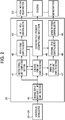
- FIG. 2 is a block diagram to show the configuration of a driving control apparatus of the present embodiment.
- the hybrid control unit 20 includes a maximum step-up input/output limit computing section 40, a motor torque limit computing section 41, a driving torque computing section 42 (required driving-torque computing section), a motor torque computing section 43, a generated power limit computing section 44, a generated power computing section 45, a generator torque limit computing section 47, a rotational speed computing section 48, and a generator torque computing section 49.
- the maximum step-up input/output limit computing section 40 computes a step-up converter upper-limit power Pvmax, which is a maximum value of the input/output power of the step-up converter 15, based on the temperature of the step-up converter 15.
- the motor torque limit computing section 41 computes motor maximum torques (Tfmax, Trmax), which are upper limit values of the motor torques (driving torques of the front motor 3 and the rear motor 5), respectively.
- the driving torque computing section 42 computes driving torque of the entire vehicle (user-requested driving torque Tur).
- the motor torque computing section 43 computes motor torques Tmf, Tmr of the front motor 3 and the rear motor 5. Then, based on these motor torques Tmf, Tmr, it controls the operation of the front motor 3 and the rear motor 5 via the inverters 12, 13.
- the generated power limit computing section 44 computes a maximum value of the generated power of the generator 7.
- the generated power computing section 45 computes engine power output, which is generated power by the generator 7, which is required corresponding to the user-requested driving torque Tur. Then, based on the engine power output in the generator 7, the operation including starting and stopping of the engine 6 is controlled via the engine control unit 30.
- the generator torque limit computing section 47 computes a limiting value of the generator torque.
- the rotational speed computing section 48 computes a rotational speed of the generator 7 corresponding to the engine power output.
- the generator torque computing section 49 computes a generator torque for achieving the rotational speed of the generator 7 which is computed at the rotational speed computing section 48. Then, based on the generator torque, it controls the generator 7 via the inverter 14.
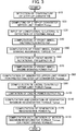
- FIG. 3 is a part of the flowchart to show the driving control procedure in the travel driving apparatus 1.
- FIG. 4 is the rest of the flowchart to show the driving control procedure in the travel driving apparatus 1.
- the hybrid control unit 20 repeatedly executes routines of driving control shown in FIGS. 3 and 4 while the vehicle power supply is turned ON.
- step S10 a temperature of the step-up converter 15 is inputted from the temperature sensor 21. Then the process proceeds to step S20.
- step S20 a step-up converter upper-limit power Pvmax is computed based on the temperature of the step-up converter 15 which has been inputted in step S10.
- the step-up converter upper-limit power Pvmax is maximum output power in the step-up converter 15.
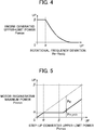
- the step-up converter upper-limit power Pvmax is computed by using, for example, a pre-stored map, and setting is made such that the step-up converter upper-limit power Pvmax becomes lower as the temperature of the step-up converter 15 becomes higher. Then, the process proceeds to step S30. Note that the control in this step corresponds to the function of the above described maximum step-up input/output limit computing section 40.
- step S30 rotational frequencies of the front wheel 2 and the rear wheel 4 are detected respectively by the front-wheel rotational frequency sensor 22 and the rear-wheel rotational frequency sensor 23, and the concerned rotational frequencies are inputted. Then, the process proceeds to step S40.
- step S40 based on the rotational frequencies of the front wheel 2 and the rear wheel 4 inputted in step S30, wheel speeds V (Vf, Vr) of the front wheel 2 and the rear wheel 4 are computed. Then, the process proceeds to S50.
- step S50 an accelerator depression amount is detected by the accelerator sensor 24 and a brake depression amount is detected by the brake sensor 25 so that the concerned accelerator depression amount and brake depression amount are inputted. Then, the process proceeds to step S60.
- step S60 based on the accelerator and brake depression amounts inputted in step S50, acceleration and braking amounts are computed. Then, the process proceeds to step S70.
- a user-requested driving torque Tur (required travel driving torque) is computed based on the wheel speeds V computed in step S40 and the acceleration and braking amounts computed in step S60.
- the user-requested driving torque Tur is a travel driving torque of the entire vehicle which is needed when accelerating/decelerating the vehicle from the current wheel speed V, that is, the travelling speed of the vehicle in correspondence with the acceleration/deceleration instruction of the driver based on the acceleration amount and the braking amount.
- the process proceeds to step S80. Note that the control of this step corresponds to the function of the above described driving torque computing section 42.
- step S80 a longitudinal acceleration and lateral acceleration of the vehicle are detected by the G sensor 26. Moreover, the steering angle is detected by the steering angle sensor 27. Then, these longitudinal acceleration, lateral acceleration, and steering angle are inputted. Thereafter, the process proceeds to step S90.
- step S90 a front-wheel distribution ratio Rdf (required distribution ratio) is computed based on vehicle travelling conditions such as the longitudinal acceleration, lateral acceleration, and steering angle, inputted in step S80.
- the front-wheel distribution ratio Rdf minimum assurance distribution ratio
- step S100 the control of this step corresponds to the distribution ratio computing section of the present invention.
- a front-wheel driving upper-limit torque Tvfmax according to step-up converter requirement is computed based on the step-up converter upper-limit power Pvmax computed in step S20 and the front wheel speed Vf of the front wheel 2 computed in step S40.
- the front-wheel driving upper-limit torque Tvfmax according to step-up converter requirement is an upper limit value of torque that the front motor 3 can output within a range not more than the step-up converter upper-limit power Pvmax, and is found by Formula (1) shown below.
- the front-wheel driving upper-limit torque Tvfmax according to step-up converter requirement is computed by using a value obtained by subtracting the engine starting power Pes from the step-up converter upper-limit power Pvmax such that engine starting is possible. Since this allows performing control always taking into consideration of the amount of power generation for starting the engine, it is possible to suppress deterioration of drivability when the engine is started.
- ⁇ mf is efficiency of the front motor 3.
- Tvfmax Pvmax ⁇ Pes ⁇ ⁇ mf / Vf / 2 ⁇ / 60
- step S110 it is determined whether or not the vehicle is travelling in the EV mode or the engine is being started, that is, whether or not the engine 6 is currently stopped.
- the process proceeds to step S120.
- the process proceeds to step S130.
- a front-wheel driving upper-limit torque Tfmax is computed.
- the front-wheel driving upper-limit torque Tfmax is found by selecting smaller one of the front-wheel driving upper-limit torque Tvfmax according to step-up converter requirement computed in step S100 and a front-wheel driving upper-limit torque Tgfmax according to another requirement, as shown by Formula (2) below.
- the front-wheel driving upper-limit torque Tgfmax according to another requirement is a front-wheel driving torque when outputs of the motor torque and the inverter are limited due to overheating or the like of the front motor 3 and the inverter 12.
- Tfmax min Tvfmax Tgfmax
- step S130 a front-wheel driving upper-limit torque Tfmax is computed.
- the front-wheel driving upper-limit torque Tfmax is supposed to be the front-wheel driving upper-limit torque Tgfmax according to another requirement as shown in Formula (3).
- Tfmax Tgfmax
- step S140 a rear-wheel driving upper-limit torque Tvrmax according to step-up converter requirement is computed.
- the rear-wheel driving upper-limit torque Tvrmax according to step-up converter requirement is computed based on a front-wheel driving upper-limit torque Tvfmax according to step-up converter requirement computed in step S100 and the front-wheel distribution ratio Rdf (minimum assurance distribution ratio) computed in step S90, as shown by Formula (4) below.
- Tvrmax Tvfmax ⁇ 1 ⁇ Rdf / Rdf
- a front-wheel driving torque Tf is computed.
- the front-wheel driving torque Tf is found by selecting smaller one of a multiplication value of the user-requested driving torque Tur computed in step S70 and the front-wheel distribution ratio Rdf (required) computed in step S90, and the front-wheel driving upper-limit torque Tfmax computed in step S120 or step S130, as shown by Formula (5) below.
- Tf min Tur ⁇ Rdf , Tfmax
- a rear-wheel driving torque Tr is computed.
- step S170 a user-requested driving power Pur is computed.
- the user-requested driving power Pur is found by multiplying the user-requested driving torque Tur computed in step S70 by the wheel speed V computed in step S40 and an overall efficiency ⁇ m of the front motor 3 and the rear motor 5 as shown by Formula (7) below.
- Pur Tur ⁇ V ⁇ 2 ⁇ / 60 / ⁇ m
- a front-wheel maximum driving power Pfmax is computed.
- the front-wheel maximum driving power Pfmax is found by multiplying the front-wheel driving upper-limit torque Tvfmax according to step-up converter requirement computed in step S100 by the wheel speed Vf of the front wheel computed in step S40 and an efficiency ⁇ mf of the front motor 3, as shown in Formula (8) below.
- Pfmax Tvfmax ⁇ Vf ⁇ 2 ⁇ / 60 / ⁇ mf
- step S190 series transition determination is performed.
- the determination of series transition is determination of shifting from the EV mode to the series mode, and is also determination of engine starting. Specifically, as shown by Formula (9) below, the determination is made based on whether or not the user-requested driving power Pur computed in step S170 is not less than a value obtained by dividing the front-wheel maximum driving power Pfmax computed in step S180 by the front-wheel distribution ratio Rdf (minimum assurance distribution ratio) computed in step S90.
- the hybrid control unit 20 controls the output of the front motor 3 based on the front-wheel driving torque Tf and controls the output of the rear motor 5 based on the rear-wheel driving torque Tr. Further, the hybrid control unit 20 performs starting control of the engine 6 with the generator 7 being the starter motor, and fuel injection and ignition control of the engine 6 via the engine control unit 30 to start the engine 6, according to determination of series transition.
- the vehicle of the present embodiment is a four-wheel drive vehicle in which the front wheel 2 can be driven by the front motor 3 and the rear wheel 4 can be driven by the rear motor 5, and in which power is supplied to the rear motor 5 and the front motor 3 from the battery 8 during the EV mode.
- output torques of the front motor 3 and the rear motor 5 are controlled by the hybrid control unit 20, and the torque ratio between the front and rear wheels is set based on an operational condition of the vehicle.
- the vehicle is mounted with the step-up converter 15 and is configured such that the front motor 3 is supplied with and driven by power which is supplied from the battery 8 and is stepped up in voltage by the step-up converter 15 so that travel driving of the front motor 3 is more efficient than that of the rear motor 5.
- the step-up converter upper-limit power Pvmax is computed by detecting the temperature of the step-up converter 15, and the front-wheel driving upper-limit torque Tfmax is set so as not to be more than the front-wheel driving upper-limit torque Tvfmax which is limited by the step-up converter upper-limit power Pvmax, thereafter performing drive limiting control for limiting the front-wheel driving torque Tf.
- the rear-wheel driving torque Tr is computed.
- FIG. 5 is a graph to show an example of the power distribution state between the front and the rear during the EV mode.
- (a) indicates that a front-rear wheel distribution ratio is 10:0
- (b) indicates that the front-rear wheel distribution ratio is 8:2
- (a) and (b) indicate the front-wheel driving power Pf and the rear-wheel driving power Pr before the drive limiting control is performed.
- (c) indicates the front-wheel driving power Pf and the rear-wheel driving power Pr when the drive limiting control is performed from the state of (a) or (b), in which the front-rear wheel distribution ratio is, for example, 7:3.
- a shaded section indicates the front-wheel driving power Pf
- a plain portion indicates the rear-wheel driving power Pr.
- the front-wheel driving power Pf is more than a value obtained by subtracting the engine starting power Pes from the step-up converter upper-limit power Pvmax so that it is not possible to supply power necessary for the front motor 3. Therefore, if the above described drive limiting control is not performed, the engine 6 must be started to supply power generated by the generator 7 to the front motor 3 to ensure the user-requested driving power Pur.
- the front-rear wheel distribution ratio is decreased to 7:3 (the front-wheel distribution ratio Rdf is 0.7), that is, changed from the required distribution ratio (10:0 or 8:2) to a executable distribution ratio (7:3), thereby reducing the front-wheel driving power Pf to a value obtained by subtracting the engine starting power Pes from the step-up converter upper-limit power Pvmax so that the decrement is switched over to the rear-wheel driving power Pr. Therefore, it is possible to ensure the user-requested driving power Pur without operating the engine 6.
- FIG. 6 is a graph to show an example of the front-rear driving torque distribution state during the EV mode.
- (a) indicates a front-rear wheel distribution ratio of 10:0
- (b) indicates a front-rear wheel distribution ratio of 8:2
- (c) indicates a front-rear wheel distribution ratio of 7:3.
- (a) to (c) indicate the front-wheel driving torque Tf and the rear-wheel driving torque Tr before the drive limiting control is performed.
- (d) indicates the front-wheel driving torque Tf and the rear-wheel driving torque Tr when the drive limiting control is performed from any of the states of (a) to (c), in which the front-rear wheel distribution ratio becomes, for example, 6:4.
- (e) indicates the front-wheel driving torque Tf and the rear-wheel driving torque Tr at the time of a maximum output torque during the EV mode, in which the front-rear wheel distribution ratio (minimum assurance distribution ratio) becomes 5:5.
- the front-rear wheel distribution ratio is decreased to, for example, 6:4 as shown by (d), thereby decreasing the front-wheel driving torque Tf to the front-wheel driving upper-limit torque Tvfmax according to step-up converter requirement, and in turn increasing the rear-wheel driving torque Tr so as to satisfy the user-requested driving torque Tur.
- the front-wheel driving power Pf is more than a value obtained by subtracting the engine starting power Pes from the step-up converter upper-limit power Pvmax, in other words, in an operational condition in which the front-wheel driving torque Tf is more than the front-wheel driving upper-limit torque Tvfmax according to step-up converter requirement, it is possible to keep the front-wheel driving torque Tf to be not more than the front-wheel driving upper-limit torque Tvfmax according to step-up converter requirement by changing the front-rear wheel distribution ratio (front-wheel distribution ratio Rdf) such that the front-wheel driving torque Tf is decreased and the rear-wheel driving torque Tr is increased.
- front-rear wheel distribution ratio front-wheel distribution ratio Rdf
- the front-wheel driving torque Tf to be the front-wheel driving upper-limit torque Tvfmax according to step-up converter requirement, it is possible to increase the front-wheel driving torque Tf as much as possible within a range of not starting the engine and make best use of driving by the front motor 3, which is more efficient than the rear motor 5, thereby suppressing power consumption.
- the hybrid control unit 20 may change the maximum value Rdrmax of the rear-wheel distribution ratio based on the operational condition. For example, the maximum value Rdrmax of the rear-wheel distribution ratio may be increased during straight travelling to more than that during turning travelling. Since straight travelling is advantageous in the aspect of vehicle travelling stability, the front-wheel driving torque Tf can be significantly decreased by increasing the maximum value Rdrmax, making it possible to further reduce the starting frequency of the engine 6, further improving fuel economy.
- the maximum value Rdmax of the rear-wheel distribution ratio may be changed depending on the lateral acceleration detected by the G sensor 26.
- the maximum value Rdrmax may be decreased as lateral acceleration increases.
- a tilting angle sensor 28 tilting angle detector
- the maximum value Rdrmax may be decreased during downhill travelling. In a situation in which the vehicle travelling stability deteriorates, such as while the lateral acceleration increases, and during downhill travelling, it is possible to improve the vehicle travelling stability by decreasing the maximum value Rdrmax of the rear-wheel distribution ratio, thereby suppressing decrease of the front-wheel driving torque Tf.
- the present invention will not be limited to the above described embodiments.
- the rear-wheel distribution ratio Rdr may be increased to be at least more than that of a case in which the drive limiting control is not performed.
- the maximum value Rdrmax of the rear-wheel distribution ratio may be constant such as 5:5, or may be changed based on information relating to the vehicle travelling stability, other than lateral acceleration or the like.
- the present invention may be widely applicable to a four-wheel drive hybrid vehicle, of which operation can be switched between an EV mode and a series mode, which includes an electrical motor for driving the front wheels and an electrical motor for driving the rear wheels, and which is equipped with a step-up converter.
Landscapes
- Engineering & Computer Science (AREA)
- Transportation (AREA)
- Mechanical Engineering (AREA)
- Chemical & Material Sciences (AREA)
- Combustion & Propulsion (AREA)
- Automation & Control Theory (AREA)
- Power Engineering (AREA)
- Life Sciences & Earth Sciences (AREA)
- Sustainable Development (AREA)
- Sustainable Energy (AREA)
- Hybrid Electric Vehicles (AREA)
- Electric Propulsion And Braking For Vehicles (AREA)
- Control Of Vehicle Engines Or Engines For Specific Uses (AREA)
- Control Of Multiple Motors (AREA)
Abstract
Description
- The present invention relates to control of travel driving of a vehicle.
- In hybrid vehicles which have been recently developed, there is known a vehicle which is switchable between a traveling mode in which driving wheels for travelling are driven by an electric motor powered by an on-board battery (EV mode) and a traveling mode in which travel driving is performed by the electric motor while power is generated by a generator driven by an internal combustion engine (series mode).
- Further, in recent years, there have been developed a hybrid vehicle which includes two electric motors as the travel diving source and a transformer (step-up converter) for stepping up the voltage outputted from an on-board battery.
- For example,
Japanese Patent Laid-Open No. 2007-325352 - Thus, as a result of supplying voltage stepped up by the transformer, travel driving by the front motor is more efficient compared with a travel driving by a rear motor not via a transformer, thus enabling suppression of power consumption.
- Meanwhile, in a vehicle which is switchable between an EV mode and a series mode as described above, when the charging rate of the on-board battery decreases or the required power for the electric motor increases in the EV mode in which the vehicle travels with the internal combustion engine being stopped, the internal combustion engine is automatically started to begin power generation, shifting into the series mode.
- Moreover, there are upper limits for input and output power for the transformer as described above in view of protecting components from generated heat or the like. Therefore, in a vehicle as described above, a problem exists in that power supply to the front motor may become insufficient in the EV mode, and the internal combustion engine must be driven to add generated power by the generator, thus causing decline in fuel economy.
- Thus, it an objective of the present invention to provide a travel driving apparatus of a vehicle, which suppresses the frequency of starting an internal combustion engine while protecting a transformer in a hybrid vehicle which is provided with an onboard transformer as well as an electrical motor for driving front wheels and an electrical motor for driving rear wheels.
- In order to achieve the above described objective, the travel driving apparatus of a vehicle of the present invention includes: a first electrical motor for driving either one of a front wheel and a rear wheel of a vehicle; a transformer for transforming voltage of power supplied from a battery mounted on the vehicle and supplying power to the first electrical motor, wherein maximum output power is limited based on a temperature condition; a second electrical motor for driving the other one of the front wheel and the rear wheel of the vehicle, the second electrical motor being supplied with power from the battery not via the transformer; an internal combustion engine for driving a generator mounted on the vehicle; a required driving-torque computing section for computing a required travel driving torque of the vehicle; and a distribution ratio computing section for computing a distribution ratio by which the required travel driving torque is distributed into a travel driving torque of the front wheel and a travel driving torque of the rear wheel based on a travelling condition of the vehicle, wherein the distribution ratio computing section sets the distribution ratio based on the maximum output power of the transformer when the vehicle is travelling with the internal combustion engine being stopped.
- As a result of this, since, in the travel driving apparatus of a vehicle according to the present invention, the distribution ratio between the travel driving torque of the front wheel and that of the rear wheel is set based on a maximum output power of the transformer, it is possible to decrease the frequency of starting the internal combustion engine while protecting the transformer.
- Moreover, preferably the internal combustion engine mounted on the vehicle drives the one of the wheels, the travel driving apparatus further includes a rotary electric machine for starting the internal combustion engine with power supplied from the battery via the transformer and, on the other hand, supplying power generated by being driven by the internal combustion engine to the battery via the transformer, and the distribution ratio computing section sets the distribution ratio based on power obtained by subtracting power of the generator needed for starting the internal combustion engine from the maximum output power.
- Since this allows the distribution ratio to be set always taking into consideration of power of the generator for starting the internal combustion engine, it is possible to improve drivability when the internal combustion engine is started.
- Moreover, preferably the travel driving apparatus of a vehicle further includes a starting determination section for performing starting determination of the internal combustion engine based on the required travel driving torque and the distribution ratio, wherein the starting determination section may start the internal combustion engine to begin power generation by the rotary electrical machine upon judging that the distribution ratio cannot be achieved.
- This makes it possible to supply necessary power to the first electrical motor and the second electrical motor, thereby ensuring travel driving torque for each wheel.
- Moreover, preferably the above-described distribution ratio computing section may restrict the distribution ratio of the travel driving torque of the rear wheel to be not more than a predetermined maximum distribution ratio.
- This makes it possible to suppress decrease of the travel driving torque of the front wheel, thereby improving vehicle travelling stability.
- Moreover, preferably the above-described distribution ratio computing section may change the maximum distribution ratio based on an operational condition of the vehicle.
- This makes it possible to suppress decrease of the travel driving torque of the front wheel based on an operational condition of the vehicle, thereby improving vehicle travelling stability.
- Moreover, preferably the above-described distribution ratio computing section may increase the maximum distribution ratio during straight travelling of the vehicle to more than the maximum distribution ratio during turning travelling of the vehicle.
- This allows the travel driving torque of the front wheel to be lowered during straight travelling, which is advantageous in the aspect of vehicle travelling stability, to reduce the starting frequency of the internal combustion engine, thereby further improving fuel economy.
- Moreover, preferably a lateral acceleration detector for detecting lateral acceleration is provided in the vehicle, and the above-described distribution ratio computing section may decrease the maximum distribution ratio as the lateral acceleration increases.
- This makes it possible to suppress decrease of the travel driving torque of the front wheel in an increasing period of the lateral acceleration in which vehicle travelling stability deteriorates, thereby improving vehicle travelling stability.
- Moreover, preferably a tilting angle detector for detecting a forward tilting angle is provided in the vehicle, and the above-described distribution ratio computing section may increase driving torque to be distributed to the rear wheel as tilting angle on an ascending gradient increases.
- This makes it possible to increase the travel driving torque to be distributed to the rear wheel during uphill travelling, thereby improving hill-climbing performance, and suppress decrease of the travel driving torque of the front wheel during downhill travelling, thereby improving vehicle travelling stability.
-
-
FIG. 1 is a schematic configuration diagram of a travel driving apparatus of a vehicle according to one embodiment of the present invention; -
FIG. 2 is a block diagram to show a configuration of a driving control apparatus of the present embodiment; -
FIG. 3 is a flowchart to show a part of driving control procedure in the travel driving apparatus according to the present embodiment; -
FIG. 4 is a flowchart to show the rest of the driving control procedure in the travel driving apparatus according to the present embodiment; -
FIG. 5 is a graph to show an example of the front-rear power distribution state during the EV mode; and -
FIG. 6 is a graph to show an example of the front-rear driving torque distribution state during the EV mode. - Hereinafter, embodiments of the present invention will be described with reference to the drawings.
-
FIG. 1 is a schematic configuration diagram of a travel driving apparatus 1 of a vehicle according to one embodiment of the present invention. - As shown in
FIG. 1 , a vehicle equipped with the travel driving apparatus 1 of one embodiment of the present invention is a four-wheel drive hybrid vehicle, which is provided with an electrically driven front motor 3 (first electrical motor) for drivingfront wheels 2, an electrically driven rear motor 5 (second electrical motor) for drivingrear wheels 4, an engine 6 (internal combustion engine), a generator 7 (rotary electric machine), and abattery 8. - The
engine 6 can drive thefront wheels 2 via a front trans-axle 16 and drive thegenerator 7 to generate power. Moreover, theengine 6 and thefront wheels 2 are configured such that power can be transferred therebetween via aclutch 11. - Moreover, the vehicle is provided with an
inverter 12 for controlling power supply to thefront motor 3, aninverter 13 for controlling power supply to therear motor 5, and aninverter 14 for controlling output of thegenerator 7. - The travel driving apparatus 1 of the present embodiment includes a step-up converter 15 (transformer) which steps up the voltage of the
battery 8 and supplies high voltage power to thefront motor 3, and at the same time steps down the high voltage power generated by thegenerator 7 to supply it to thebattery 8 and therear motor 5. - The
front motor 3, which can be driven by being supplied with power from thebattery 8 via the step-up converter 15 and theinverter 12, and also can be driven by being supplied with power from thegenerator 7 via theinverter 14 and theinverter 12, drives thefront wheels 2 via the front trans-axle 16. - The
rear motor 5, which is driven by being supplied with power from thebattery 8 via theinverter 13, drives therear wheel 4 via a rear trans-axle 17. - The power generated by the
generator 7 and outputted from theinverter 14 allows charging of thebattery 8 via the step-up converter 15, and can also be supplied to thefront motor 3 via theinverter 12 and to therear motor 5 via theinverter 13. - Moreover, the
generator 7, which is driven by being supplied with power from thebattery 8 via the step-up converter 15 and theinverter 14, has a function as a starter motor for starting theengine 6. - The
battery 8, which is made up of a secondary cell battery such as a lithium-ion battery, has a battery module not shown and made up of a plurality of battery cells brought together. - Operation of each of the
inverter 12, theinverter 13, theinverter 14, and the step-up converter 15 is controlled by a control signal from a hybrid control unit 20 (a distribution ratio computing section and a starting determination section) mounted on the vehicle. - The step-
up converter 15 is provided with atemperature sensor 21 for detecting the temperature of a component (element, etc.) of the step-up converter 15. - Further, the vehicle is provided with a front-wheel
rotational frequency sensor 22 for detecting the number of rotation per unit time of thefront wheel 2, a rear-wheelrotational frequency sensor 23 for detecting the number of rotation per unit time of therear wheel 4, anaccelerator sensor 24 for detecting an accelerator depression amount, abrake sensor 25 for detecting a brake depression amount, a G sensor 26 (lateral acceleration detector) for detecting longitudinal acceleration and lateral acceleration of the vehicle, asteering angle sensor 27 for detecting a steering control angle (steering angle), and anengine control unit 30 for controlling the driving of theengine 6. - The
engine control unit 30 controls the driving of theengine 6 based on a control signal from thehybrid control unit 20. - The
hybrid control unit 20, which is a control apparatus for performing comprehensive control of the vehicle, is configured to include an input/output apparatus, a storage apparatus (ROM, RAM, non-volatile RAM, etc.), a central processing unit (CPU), and a timer, etc. - The input side of the
hybrid control unit 20 is connected with each of theinverters 12 to 14, theengine control unit 30, thetemperature sensor 21, the front-wheelrotational frequency sensor 22, the rear-wheelrotational frequency sensor 23, theaccelerator sensor 24, thebrake sensor 25, theG sensor 26, and thesteering angle sensor 27, and is inputted with detection and operation information from these equipment. - On the other hand, the output side of the
hybrid control unit 20 is connected with each of theinverters 12 to 14, theengine control unit 30, and theclutch 11. - Then, the
hybrid control unit 20 transmits a control signal to theengine control unit 30, each of theinverters clutch 11 to control the switching of the traveling mode (EV mode, series mode, and parallel mode) which involves engagement and disengagement of theclutch 11, output torques of theengine 6, thefront motor 3 and therear motor 5, and generated power of thegenerator 7 based on various detection amounts such as accelerator depression amount from theaccelerator sensor 24 of the vehicle, and various operation information. - In the parallel mode, the
front wheels 2 are mechanically driven by the output of theengine 6 with theclutch 11 being engaged, and are also driven to travel by thefront motor 3 and therear motor 5. - In the EV mode and the series mode, the
clutch 11 is disengaged. In the EV mode, theengine 6 is stopped, and thefront motor 3 and therear motor 5 are driven by power from thebattery 8. In the series mode, theengine 6 is operated to cause thegenerator 7 to generate power, thereby supplying power to and driving thefront motor 3 and therear motor 5. -
FIG. 2 is a block diagram to show the configuration of a driving control apparatus of the present embodiment. - As shown in
FIG. 2 , thehybrid control unit 20 includes a maximum step-up input/outputlimit computing section 40, a motor torquelimit computing section 41, a driving torque computing section 42 (required driving-torque computing section), a motortorque computing section 43, a generated powerlimit computing section 44, a generatedpower computing section 45, a generator torquelimit computing section 47, a rotationalspeed computing section 48, and a generatortorque computing section 49. - The maximum step-up input/output
limit computing section 40 computes a step-up converter upper-limit power Pvmax, which is a maximum value of the input/output power of the step-up converter 15, based on the temperature of the step-up converter 15. - The motor torque
limit computing section 41 computes motor maximum torques (Tfmax, Trmax), which are upper limit values of the motor torques (driving torques of thefront motor 3 and the rear motor 5), respectively. - The driving
torque computing section 42 computes driving torque of the entire vehicle (user-requested driving torque Tur). - The motor
torque computing section 43 computes motor torques Tmf, Tmr of thefront motor 3 and therear motor 5. Then, based on these motor torques Tmf, Tmr, it controls the operation of thefront motor 3 and therear motor 5 via theinverters - The generated power
limit computing section 44 computes a maximum value of the generated power of thegenerator 7. - The generated
power computing section 45 computes engine power output, which is generated power by thegenerator 7, which is required corresponding to the user-requested driving torque Tur. Then, based on the engine power output in thegenerator 7, the operation including starting and stopping of theengine 6 is controlled via theengine control unit 30. - The generator torque
limit computing section 47 computes a limiting value of the generator torque. - The rotational
speed computing section 48 computes a rotational speed of thegenerator 7 corresponding to the engine power output. - The generator
torque computing section 49 computes a generator torque for achieving the rotational speed of thegenerator 7 which is computed at the rotationalspeed computing section 48. Then, based on the generator torque, it controls thegenerator 7 via theinverter 14. - Next, driving control by the travel driving apparatus 1 of the present embodiment will be described in detail by using
FIGS. 3 and4 . -
FIG. 3 is a part of the flowchart to show the driving control procedure in the travel driving apparatus 1.FIG. 4 is the rest of the flowchart to show the driving control procedure in the travel driving apparatus 1. - The
hybrid control unit 20 repeatedly executes routines of driving control shown inFIGS. 3 and4 while the vehicle power supply is turned ON. - First, in step S10, a temperature of the step-up
converter 15 is inputted from thetemperature sensor 21. Then the process proceeds to step S20. - In step S20, a step-up converter upper-limit power Pvmax is computed based on the temperature of the step-up
converter 15 which has been inputted in step S10. The step-up converter upper-limit power Pvmax is maximum output power in the step-upconverter 15. The step-up converter upper-limit power Pvmax is computed by using, for example, a pre-stored map, and setting is made such that the step-up converter upper-limit power Pvmax becomes lower as the temperature of the step-upconverter 15 becomes higher. Then, the process proceeds to step S30. Note that the control in this step corresponds to the function of the above described maximum step-up input/outputlimit computing section 40. - In step S30, rotational frequencies of the
front wheel 2 and therear wheel 4 are detected respectively by the front-wheelrotational frequency sensor 22 and the rear-wheelrotational frequency sensor 23, and the concerned rotational frequencies are inputted. Then, the process proceeds to step S40. - In step S40, based on the rotational frequencies of the
front wheel 2 and therear wheel 4 inputted in step S30, wheel speeds V (Vf, Vr) of thefront wheel 2 and therear wheel 4 are computed. Then, the process proceeds to S50. - In step S50, an accelerator depression amount is detected by the
accelerator sensor 24 and a brake depression amount is detected by thebrake sensor 25 so that the concerned accelerator depression amount and brake depression amount are inputted. Then, the process proceeds to step S60. - In step S60, based on the accelerator and brake depression amounts inputted in step S50, acceleration and braking amounts are computed. Then, the process proceeds to step S70.
- In step S70, a user-requested driving torque Tur (required travel driving torque) is computed based on the wheel speeds V computed in step S40 and the acceleration and braking amounts computed in step S60. The user-requested driving torque Tur is a travel driving torque of the entire vehicle which is needed when accelerating/decelerating the vehicle from the current wheel speed V, that is, the travelling speed of the vehicle in correspondence with the acceleration/deceleration instruction of the driver based on the acceleration amount and the braking amount. Then, the process proceeds to step S80. Note that the control of this step corresponds to the function of the above described driving
torque computing section 42. - In step S80, a longitudinal acceleration and lateral acceleration of the vehicle are detected by the
G sensor 26. Moreover, the steering angle is detected by thesteering angle sensor 27. Then, these longitudinal acceleration, lateral acceleration, and steering angle are inputted. Thereafter, the process proceeds to step S90. - In step S90, a front-wheel distribution ratio Rdf (required distribution ratio) is computed based on vehicle travelling conditions such as the longitudinal acceleration, lateral acceleration, and steering angle, inputted in step S80. Note that the front-wheel distribution ratio Rdf (minimum assurance distribution ratio) is set between 100% and 50% in the vehicle of the present embodiment. Then, the process proceeds to step S100. Note that the control of this step corresponds to the distribution ratio computing section of the present invention.
- In step S100, a front-wheel driving upper-limit torque Tvfmax according to step-up converter requirement is computed based on the step-up converter upper-limit power Pvmax computed in step S20 and the front wheel speed Vf of the
front wheel 2 computed in step S40. The front-wheel driving upper-limit torque Tvfmax according to step-up converter requirement is an upper limit value of torque that thefront motor 3 can output within a range not more than the step-up converter upper-limit power Pvmax, and is found by Formula (1) shown below. As shown by Formula (1), the front-wheel driving upper-limit torque Tvfmax according to step-up converter requirement is computed by using a value obtained by subtracting the engine starting power Pes from the step-up converter upper-limit power Pvmax such that engine starting is possible. Since this allows performing control always taking into consideration of the amount of power generation for starting the engine, it is possible to suppress deterioration of drivability when the engine is started. Note that in Formula (1), ηmf is efficiency of thefront motor 3.
- Then, the process proceeds to step S110.
- In step S110, it is determined whether or not the vehicle is travelling in the EV mode or the engine is being started, that is, whether or not the
engine 6 is currently stopped. When the vehicle is travelling in the EV mode or the engine is being started, that is, theengine 6 is currently stopped, the process proceeds to step S120. When the vehicle is not travelling in the EV mode, or the engine is not being started, that is, theengine 6 is currently being operated, the process proceeds to step S130. - In step S120, a front-wheel driving upper-limit torque Tfmax is computed. In this step, the front-wheel driving upper-limit torque Tfmax is found by selecting smaller one of the front-wheel driving upper-limit torque Tvfmax according to step-up converter requirement computed in step S100 and a front-wheel driving upper-limit torque Tgfmax according to another requirement, as shown by Formula (2) below. Note that, the front-wheel driving upper-limit torque Tgfmax according to another requirement is a front-wheel driving torque when outputs of the motor torque and the inverter are limited due to overheating or the like of the
front motor 3 and theinverter 12.
- Then, the process proceeds to step S140.
- In step S130, a front-wheel driving upper-limit torque Tfmax is computed. In the present step, the front-wheel driving upper-limit torque Tfmax is supposed to be the front-wheel driving upper-limit torque Tgfmax according to another requirement as shown in Formula (3).

- Then, the process proceeds to step S140.
- In step S140, a rear-wheel driving upper-limit torque Tvrmax according to step-up converter requirement is computed. The rear-wheel driving upper-limit torque Tvrmax according to step-up converter requirement is computed based on a front-wheel driving upper-limit torque Tvfmax according to step-up converter requirement computed in step S100 and the front-wheel distribution ratio Rdf (minimum assurance distribution ratio) computed in step S90, as shown by Formula (4) below.

- Then, the process proceeds to S150 in
FIG. 4 . - In step S150, a front-wheel driving torque Tf is computed. The front-wheel driving torque Tf is found by selecting smaller one of a multiplication value of the user-requested driving torque Tur computed in step S70 and the front-wheel distribution ratio Rdf (required) computed in step S90, and the front-wheel driving upper-limit torque Tfmax computed in step S120 or step S130, as shown by Formula (5) below.

- Then, the process proceeds to S160.
- In step S160, a rear-wheel driving torque Tr is computed. The rear-wheel driving torque Tf is found by selecting smaller one of a value obtained by subtracting the front-wheel driving torque Tf computed in step S150 from the user-requested driving torque Tur computed in step S70, and the rear-wheel driving upper-limit torque Tvrmax according to step-up converter requirement computed in step S140, as shown by Formula (6) below.

- Then, the process proceeds to S170.
- In step S170, a user-requested driving power Pur is computed. The user-requested driving power Pur is found by multiplying the user-requested driving torque Tur computed in step S70 by the wheel speed V computed in step S40 and an overall efficiency ηm of the
front motor 3 and therear motor 5 as shown by Formula (7) below.
- Then, the process proceeds to S180.
- In step S180, a front-wheel maximum driving power Pfmax is computed. The front-wheel maximum driving power Pfmax is found by multiplying the front-wheel driving upper-limit torque Tvfmax according to step-up converter requirement computed in step S100 by the wheel speed Vf of the front wheel computed in step S40 and an efficiency ηmf of the
front motor 3, as shown in Formula (8) below.
- Then, the process proceeds to S190.
- In step S190, series transition determination is performed. The determination of series transition is determination of shifting from the EV mode to the series mode, and is also determination of engine starting. Specifically, as shown by Formula (9) below, the determination is made based on whether or not the user-requested driving power Pur computed in step S170 is not less than a value obtained by dividing the front-wheel maximum driving power Pfmax computed in step S180 by the front-wheel distribution ratio Rdf (minimum assurance distribution ratio) computed in step S90.

- When it is determined that the user-requested driving power Pur is not less than a value obtained by dividing the front-wheel maximum driving power Pfmax by the front-wheel distribution ratio Rdf, shifting to the series mode in which the engine is started is determined. When it is determined that the user-requested driving power Pur is less than a value obtained by dividing the front-wheel maximum driving power Pfmax by the front-wheel distribution ratio Rdf, the EV mode is continued without starting the
engine 6. Note that the control of the present step corresponds to the starting determination section of the present invention. Then, this routine is ended. - Through the above described control, the front-wheel driving torque Tf and the rear-wheel driving torque Tr are found. Then, the
hybrid control unit 20 controls the output of thefront motor 3 based on the front-wheel driving torque Tf and controls the output of therear motor 5 based on the rear-wheel driving torque Tr. Further, thehybrid control unit 20 performs starting control of theengine 6 with thegenerator 7 being the starter motor, and fuel injection and ignition control of theengine 6 via theengine control unit 30 to start theengine 6, according to determination of series transition. - The vehicle of the present embodiment is a four-wheel drive vehicle in which the
front wheel 2 can be driven by thefront motor 3 and therear wheel 4 can be driven by therear motor 5, and in which power is supplied to therear motor 5 and thefront motor 3 from thebattery 8 during the EV mode. As described above, output torques of thefront motor 3 and therear motor 5 are controlled by thehybrid control unit 20, and the torque ratio between the front and rear wheels is set based on an operational condition of the vehicle. - Further, the vehicle is mounted with the step-up
converter 15 and is configured such that thefront motor 3 is supplied with and driven by power which is supplied from thebattery 8 and is stepped up in voltage by the step-upconverter 15 so that travel driving of thefront motor 3 is more efficient than that of therear motor 5. - Then, in the present embodiment, in the driving control as shown above in
FIGS. 3 and4 , the step-up converter upper-limit power Pvmax is computed by detecting the temperature of the step-upconverter 15, and the front-wheel driving upper-limit torque Tfmax is set so as not to be more than the front-wheel driving upper-limit torque Tvfmax which is limited by the step-up converter upper-limit power Pvmax, thereafter performing drive limiting control for limiting the front-wheel driving torque Tf. Then, after the front-wheel driving torque Tf is preferentially set based on the limitation of the step-upconverter 15, the rear-wheel driving torque Tr is computed. -
FIG. 5 is a graph to show an example of the power distribution state between the front and the rear during the EV mode. InFIG. 5 , (a) indicates that a front-rear wheel distribution ratio is 10:0, (b) indicates that the front-rear wheel distribution ratio is 8:2, and (a) and (b) indicate the front-wheel driving power Pf and the rear-wheel driving power Pr before the drive limiting control is performed. InFIG. 5 , (c) indicates the front-wheel driving power Pf and the rear-wheel driving power Pr when the drive limiting control is performed from the state of (a) or (b), in which the front-rear wheel distribution ratio is, for example, 7:3. Note that inFIG. 5 , a shaded section indicates the front-wheel driving power Pf, and a plain portion indicates the rear-wheel driving power Pr. - As shown by (a) and (b) in
FIG. 5 , in the EV mode in which theengine 6 is in a stopped state, when, for example, the front-rear wheel distribution ratio is 10:0 or 8:2 based on an operational condition, the front-wheel driving power Pf is more than a value obtained by subtracting the engine starting power Pes from the step-up converter upper-limit power Pvmax so that it is not possible to supply power necessary for thefront motor 3. Therefore, if the above described drive limiting control is not performed, theengine 6 must be started to supply power generated by thegenerator 7 to thefront motor 3 to ensure the user-requested driving power Pur. - In contrast to this, in the present embodiment, as shown in (c), for example, the front-rear wheel distribution ratio is decreased to 7:3 (the front-wheel distribution ratio Rdf is 0.7), that is, changed from the required distribution ratio (10:0 or 8:2) to a executable distribution ratio (7:3), thereby reducing the front-wheel driving power Pf to a value obtained by subtracting the engine starting power Pes from the step-up converter upper-limit power Pvmax so that the decrement is switched over to the rear-wheel driving power Pr. Therefore, it is possible to ensure the user-requested driving power Pur without operating the
engine 6. -
FIG. 6 is a graph to show an example of the front-rear driving torque distribution state during the EV mode. InFIG. 6 , (a) indicates a front-rear wheel distribution ratio of 10:0, (b) indicates a front-rear wheel distribution ratio of 8:2, and (c) indicates a front-rear wheel distribution ratio of 7:3. Further, (a) to (c) indicate the front-wheel driving torque Tf and the rear-wheel driving torque Tr before the drive limiting control is performed. InFIG. 6 , (d) indicates the front-wheel driving torque Tf and the rear-wheel driving torque Tr when the drive limiting control is performed from any of the states of (a) to (c), in which the front-rear wheel distribution ratio becomes, for example, 6:4. InFIG. 6 , (e) indicates the front-wheel driving torque Tf and the rear-wheel driving torque Tr at the time of a maximum output torque during the EV mode, in which the front-rear wheel distribution ratio (minimum assurance distribution ratio) becomes 5:5. - As shown by (a) to (c) in
FIG. 6 , when for example the front-rear wheel distribution ratio is 10:0, or 8:2, or 7:3 based on the operational condition during the EV mode, since the front-wheel driving torque Tf is more than the front-wheel driving upper-limit torque Tvfmax according to step-up converter requirement, it is necessary to start theengine 6 for achieving the concerned front-wheel driving torque Tf, thereby supplying power from thegenerator 7 to thefront motor 3. - In contrast to this, in the present embodiment, the front-rear wheel distribution ratio is decreased to, for example, 6:4 as shown by (d), thereby decreasing the front-wheel driving torque Tf to the front-wheel driving upper-limit torque Tvfmax according to step-up converter requirement, and in turn increasing the rear-wheel driving torque Tr so as to satisfy the user-requested driving torque Tur.
- In this way, in the present embodiment, during the EV mode in which the
engine 6 is stopped, when the front-wheel driving power Pf is more than a value obtained by subtracting the engine starting power Pes from the step-up converter upper-limit power Pvmax, in other words, in an operational condition in which the front-wheel driving torque Tf is more than the front-wheel driving upper-limit torque Tvfmax according to step-up converter requirement, it is possible to keep the front-wheel driving torque Tf to be not more than the front-wheel driving upper-limit torque Tvfmax according to step-up converter requirement by changing the front-rear wheel distribution ratio (front-wheel distribution ratio Rdf) such that the front-wheel driving torque Tf is decreased and the rear-wheel driving torque Tr is increased. - As a result of this, it is possible to suppress the frequency of starting the
engine 6, thereby improving fuel economy, while satisfying the user-requested driving power Pur and ensuring the user-requested driving torque Tur. - Moreover, by adjusting the front-wheel driving torque Tf to be the front-wheel driving upper-limit torque Tvfmax according to step-up converter requirement, it is possible to increase the front-wheel driving torque Tf as much as possible within a range of not starting the engine and make best use of driving by the
front motor 3, which is more efficient than therear motor 5, thereby suppressing power consumption. - Moreover, since it is restricted that the rear-wheel driving torque Tr increases to a front-rear wheel distribution ratio of 5:5 or more, i.e., that the maximum value Rdrmax (predetermined maximum distribution ratio) of the rear-wheel distribution ratio Rdr (= 1 - Rdf) is 0.5, even if drive limiting control to limit the front-wheel driving torque Tf is performed as described above, it is possible to suppress excessive decrease of the front-wheel driving torque Tf, thereby ensuring vehicle travelling stability.
- Further, the
hybrid control unit 20 may change the maximum value Rdrmax of the rear-wheel distribution ratio based on the operational condition. For example, the maximum value Rdrmax of the rear-wheel distribution ratio may be increased during straight travelling to more than that during turning travelling. Since straight travelling is advantageous in the aspect of vehicle travelling stability, the front-wheel driving torque Tf can be significantly decreased by increasing the maximum value Rdrmax, making it possible to further reduce the starting frequency of theengine 6, further improving fuel economy. - Moreover, the maximum value Rdmax of the rear-wheel distribution ratio may be changed depending on the lateral acceleration detected by the
G sensor 26. For example, the maximum value Rdrmax may be decreased as lateral acceleration increases. Alternatively, a tilting angle sensor 28 (tilting angle detector) may be provided in the vehicle, and the maximum value Rdrmax may be decreased during downhill travelling. In a situation in which the vehicle travelling stability deteriorates, such as while the lateral acceleration increases, and during downhill travelling, it is possible to improve the vehicle travelling stability by decreasing the maximum value Rdrmax of the rear-wheel distribution ratio, thereby suppressing decrease of the front-wheel driving torque Tf. - Note that the present invention will not be limited to the above described embodiments. For example, when the above described drive limiting control is performed, the rear-wheel distribution ratio Rdr may be increased to be at least more than that of a case in which the drive limiting control is not performed. The maximum value Rdrmax of the rear-wheel distribution ratio may be constant such as 5:5, or may be changed based on information relating to the vehicle travelling stability, other than lateral acceleration or the like. The present invention may be widely applicable to a four-wheel drive hybrid vehicle, of which operation can be switched between an EV mode and a series mode, which includes an electrical motor for driving the front wheels and an electrical motor for driving the rear wheels, and which is equipped with a step-up converter.
Claims (8)
- A travel driving apparatus (1) of a vehicle, comprising:a first electrical motor (3) for driving either one of a front wheel (2) and a rear wheel (4) of a vehicle;a transformer (15) for transforming voltage of power supplied from a battery (8) mounted on the vehicle and supplying power to the first electrical motor (3), wherein maximum output power is limited based on a temperature condition;a second electrical motor (5) for driving the other one of the front wheel (2) and the rear wheel (4) of the vehicle, the second electrical motor (5) being supplied with power from the battery (8) not via the transformer (15) ;an internal combustion engine (6) for driving a generator (7) mounted on the vehicle;a required driving-torque computing section (42) for computing a required travel driving torque of the vehicle; anda distribution ratio computing section (20) for computing a distribution ratio by which the required travel driving torque is distributed into a travel driving torque of the front wheel and a travel driving torque of the rear wheel based on a travelling condition of the vehicle, the travel driving apparatus (1), characterized in thatthe distribution ratio computing section (20) sets the distribution ratio based on the maximum output power of the transformer (15) when the vehicle is travelling with the internal combustion engine (6) being stopped.
- The travel driving apparatus of a vehicle according to claim 1, characterized in that
the internal combustion engine (6) mounted on the vehicle drives the one of the wheels,
the travel driving apparatus further comprises a rotary electric machine (7) for starting the internal combustion engine (6) with power supplied from the battery (8) via the transformer (15) and, on the other hand, supplying power generated by being driven by the internal combustion engine (6) to the battery (8) via the transformer (15), and
the distribution ratio computing section (20) sets the distribution ratio based on power obtained by subtracting power of the generator (7) needed for starting the internal combustion engine (6) from the maximum output power. - The travel driving apparatus of a vehicle according to claim 2, characterized in that the travel driving apparatus further comprises:a starting determination section (20) for performing starting determination of the internal combustion engine (6) based on the required travel driving torque and the distribution ratio, andthe starting determination section (20) starts the internal combustion engine (6) to begin power generation at the rotary electric machine (7) upon judging that the distribution ratio cannot be achieved.
- The travel driving apparatus of a vehicle according to claims 1 to 3, characterized in that
the distribution ratio computing section (20) restricts the distribution ratio of the travel driving torque of the rear wheel to be not more than a predetermined maximum distribution ratio. - The travel driving apparatus of a vehicle according to claim 4, characterized in that
the distribution ratio computing section (20) changes the maximum distribution ratio based on an operational condition of the vehicle. - The travel driving apparatus of a vehicle according to claim 5, characterized in that
the distribution ratio computing section (20) increases the maximum distribution ratio during straight travelling of the vehicle to more than the maximum distribution ratio during turning travelling of the vehicle. - The travel driving apparatus of a vehicle according to claim 5, characterized in that
a lateral acceleration detector (26) for detecting lateral acceleration is provided in the vehicle, and
the distribution ratio computing section (20) decreases the maximum distribution ratio as the lateral acceleration increases. - The travel driving apparatus of a vehicle according to claim 5, characterized in that
a tilting angle detector (28) for detecting a forward tilting angle is provided in the vehicle, and
the distribution ratio computing section (20) increases driving torque to be distributed to the rear wheel as tilting angle on an ascending gradient increases.
Applications Claiming Priority (1)
| Application Number | Priority Date | Filing Date | Title |
|---|---|---|---|
| JP2016068408A JP6646260B2 (en) | 2016-03-30 | 2016-03-30 | Vehicle drive system |
Publications (2)
| Publication Number | Publication Date |
|---|---|
| EP3238971A1 true EP3238971A1 (en) | 2017-11-01 |
| EP3238971B1 EP3238971B1 (en) | 2023-06-21 |
Family
ID=58464264
Family Applications (1)
| Application Number | Title | Priority Date | Filing Date |
|---|---|---|---|
| EP17163699.6A Active EP3238971B1 (en) | 2016-03-30 | 2017-03-29 | Travel driving apparatus of vehicle |
Country Status (4)
| Country | Link |
|---|---|
| US (1) | US10059324B2 (en) |
| EP (1) | EP3238971B1 (en) |
| JP (1) | JP6646260B2 (en) |
| CN (1) | CN107264516B (en) |
Cited By (1)
| Publication number | Priority date | Publication date | Assignee | Title |
|---|---|---|---|---|
| FR3081011A1 (en) * | 2018-05-09 | 2019-11-15 | Psa Automobiles Sa | METHOD FOR MANAGING THE TRAINING OF A HYBRID AUTOMOBILE VEHICLE |
Families Citing this family (12)
| Publication number | Priority date | Publication date | Assignee | Title |
|---|---|---|---|---|
| JP6718427B2 (en) * | 2017-12-01 | 2020-07-08 | 株式会社Subaru | Vehicle control device and vehicle control method |
| JP7339797B2 (en) | 2019-07-16 | 2023-09-06 | 株式会社Subaru | vehicle |
| CN112319478B (en) * | 2019-07-31 | 2022-04-15 | 比亚迪股份有限公司 | Vehicle drive mode switching method, device and storage medium, electric commercial vehicle |
| JP7041704B2 (en) * | 2020-03-12 | 2022-03-24 | 本田技研工業株式会社 | Behavior control device and behavior control method |
| JP7343428B2 (en) * | 2020-03-16 | 2023-09-12 | トヨタ自動車株式会社 | Hybrid vehicle drive system |
| JP7440377B2 (en) * | 2020-08-24 | 2024-02-28 | 株式会社Subaru | vehicle control system |
| JP7396330B2 (en) * | 2021-06-04 | 2023-12-12 | トヨタ自動車株式会社 | Vehicle drive system |
| WO2023141160A1 (en) * | 2022-01-19 | 2023-07-27 | Lordstown EV Corporation | Electric vehicle control systems and methods |
| JP7704055B2 (en) * | 2022-03-22 | 2025-07-08 | トヨタ自動車株式会社 | Vehicle control device |
| CN114834437B (en) * | 2022-05-25 | 2025-11-14 | 中国第一汽车股份有限公司 | Control methods for dual-motor hybrid vehicles |
| JP7754011B2 (en) * | 2022-07-12 | 2025-10-15 | トヨタ自動車株式会社 | Electric vehicle control device |
| CN118665148B (en) * | 2024-07-22 | 2026-03-10 | 广州汽车集团股份有限公司 | Driving system and vehicle |
Citations (8)
| Publication number | Priority date | Publication date | Assignee | Title |
|---|---|---|---|---|
| JP2007325352A (en) | 2006-05-30 | 2007-12-13 | Toyota Motor Corp | Power output apparatus and vehicle equipped with the same |
| EP2025570A1 (en) * | 2006-05-24 | 2009-02-18 | Toyota Jidosha Kabushiki Kaisha | Drive force control device for four-wheel drive vehicle |
| US20110260667A1 (en) * | 2010-04-22 | 2011-10-27 | General Electric Company | Power control on a multi-motion electric drive system |
| US20110288706A1 (en) * | 2010-05-24 | 2011-11-24 | Toyota Jidosha Kabushiki Kaisha | Electric vehicle |
| JP2014121961A (en) * | 2012-12-21 | 2014-07-03 | Mitsubishi Motors Corp | Engine start control device for hybrid vehicle |
| JP2014125053A (en) * | 2012-12-26 | 2014-07-07 | Toyota Motor Corp | Electric vehicle, and control method for the same |
| JP2014176168A (en) * | 2013-03-07 | 2014-09-22 | Honda Motor Co Ltd | Power controller and output limitation method |
| WO2015166325A1 (en) * | 2014-04-30 | 2015-11-05 | Toyota Jidosha Kabushiki Kaisha | Drive control system for vehicle |
Family Cites Families (5)
| Publication number | Priority date | Publication date | Assignee | Title |
|---|---|---|---|---|
| JP2005053317A (en) * | 2003-08-04 | 2005-03-03 | Nissan Motor Co Ltd | Control device for hybrid vehicle |
| JP4165344B2 (en) * | 2003-08-29 | 2008-10-15 | トヨタ自動車株式会社 | Vehicle control device |
| JP4207966B2 (en) * | 2005-08-25 | 2009-01-14 | トヨタ自動車株式会社 | POWER OUTPUT DEVICE, ITS CONTROL METHOD, AND VEHICLE |
| JP5682515B2 (en) * | 2011-09-08 | 2015-03-11 | 三菱自動車工業株式会社 | Control device for hybrid electric vehicle |
| CN103963627A (en) * | 2014-04-29 | 2014-08-06 | 华中科技大学 | Series-parallel connection plug-in hybrid electrical vehicle driving system and method |
-
2016
- 2016-03-30 JP JP2016068408A patent/JP6646260B2/en active Active
-
2017
- 2017-03-13 US US15/456,975 patent/US10059324B2/en active Active
- 2017-03-29 EP EP17163699.6A patent/EP3238971B1/en active Active
- 2017-03-29 CN CN201710201555.6A patent/CN107264516B/en active Active
Patent Citations (8)
| Publication number | Priority date | Publication date | Assignee | Title |
|---|---|---|---|---|
| EP2025570A1 (en) * | 2006-05-24 | 2009-02-18 | Toyota Jidosha Kabushiki Kaisha | Drive force control device for four-wheel drive vehicle |
| JP2007325352A (en) | 2006-05-30 | 2007-12-13 | Toyota Motor Corp | Power output apparatus and vehicle equipped with the same |
| US20110260667A1 (en) * | 2010-04-22 | 2011-10-27 | General Electric Company | Power control on a multi-motion electric drive system |
| US20110288706A1 (en) * | 2010-05-24 | 2011-11-24 | Toyota Jidosha Kabushiki Kaisha | Electric vehicle |
| JP2014121961A (en) * | 2012-12-21 | 2014-07-03 | Mitsubishi Motors Corp | Engine start control device for hybrid vehicle |
| JP2014125053A (en) * | 2012-12-26 | 2014-07-07 | Toyota Motor Corp | Electric vehicle, and control method for the same |
| JP2014176168A (en) * | 2013-03-07 | 2014-09-22 | Honda Motor Co Ltd | Power controller and output limitation method |
| WO2015166325A1 (en) * | 2014-04-30 | 2015-11-05 | Toyota Jidosha Kabushiki Kaisha | Drive control system for vehicle |
Cited By (4)
| Publication number | Priority date | Publication date | Assignee | Title |
|---|---|---|---|---|
| FR3081011A1 (en) * | 2018-05-09 | 2019-11-15 | Psa Automobiles Sa | METHOD FOR MANAGING THE TRAINING OF A HYBRID AUTOMOBILE VEHICLE |
| WO2019215401A3 (en) * | 2018-05-09 | 2020-02-27 | Psa Automobiles Sa | Method of controlling a hybrid motor vehicle drive |
| CN112105536A (en) * | 2018-05-09 | 2020-12-18 | 标致雪铁龙汽车股份有限公司 | Method for managing the drive of a hybrid motor vehicle |
| CN112105536B (en) * | 2018-05-09 | 2024-05-31 | 标致雪铁龙汽车股份有限公司 | Method for managing the drive of a hybrid motor vehicle |
Also Published As
| Publication number | Publication date |
|---|---|
| CN107264516B (en) | 2019-09-27 |
| JP6646260B2 (en) | 2020-02-14 |
| CN107264516A (en) | 2017-10-20 |
| JP2017178053A (en) | 2017-10-05 |
| EP3238971B1 (en) | 2023-06-21 |
| US20170282891A1 (en) | 2017-10-05 |
| US10059324B2 (en) | 2018-08-28 |
Similar Documents
| Publication | Publication Date | Title |
|---|---|---|
| EP3238971B1 (en) | Travel driving apparatus of vehicle | |
| EP3225445B1 (en) | Travel driving apparatus of vehicle | |
| EP3225446B1 (en) | Travel driving apparatus of vehicle | |
| US10086825B2 (en) | Travel driving apparatus of vehicle | |
| EP2127984B1 (en) | Control method of hybrid vehicles | |
| KR101836693B1 (en) | Apparatus and method for controlling torque intervention of hybrid vehicle | |
| EP3138713B1 (en) | Hybrid vehicle | |
| US9739222B2 (en) | System and method for controlling torque intervention of hybrid electric vehicle during shift | |
| EP3216639A1 (en) | Control apparatus for hybrid vehicle, hybrid vehicle, and control method for hybrid vehicle | |
| US20220194354A1 (en) | Method of supervisory control for power management of a parallel two motor hybrid powertrain | |
| KR101198808B1 (en) | Method for controling engine idle of hybrid electric vehicle | |
| JP7235173B2 (en) | Hybrid vehicle control device | |
| JP2012239282A (en) | Vehicle, and control method thereof | |
| JP6729221B2 (en) | Hybrid car | |
| JP2014043183A (en) | Hybrid vehicle | |
| JP2011225077A (en) | Hybrid automobile | |
| JP2010252427A (en) | Automobile and charging method for secondary battery mounted on the same | |
| JP2018007457A (en) | Automobile | |
| WO2026083487A1 (en) | Drive control device for hybrid vehicle | |
| JP2024164741A (en) | Vehicle control device | |
| JP2015009726A (en) | Control device for hybrid vehicle | |
| JP2019107958A (en) | Hybrid vehicle |
Legal Events
| Date | Code | Title | Description |
|---|---|---|---|
| PUAI | Public reference made under article 153(3) epc to a published international application that has entered the european phase |
Free format text: ORIGINAL CODE: 0009012 |
|
| STAA | Information on the status of an ep patent application or granted ep patent |
Free format text: STATUS: REQUEST FOR EXAMINATION WAS MADE |
|
| 17P | Request for examination filed |
Effective date: 20170329 |
|
| AK | Designated contracting states |
Kind code of ref document: A1 Designated state(s): AL AT BE BG CH CY CZ DE DK EE ES FI FR GB GR HR HU IE IS IT LI LT LU LV MC MK MT NL NO PL PT RO RS SE SI SK SM TR |
|
| AX | Request for extension of the european patent |
Extension state: BA ME |
|
| XX | Miscellaneous (additional remarks) |
Free format text: MISSING DRAWINGS FILED IN ACCORDANCE WITH RULE 56(3) EPC. |
|
| RAP1 | Party data changed (applicant data changed or rights of an application transferred) |
Owner name: MITSUBISHI JIDOSHA KOGYO KABUSHIKI KAISHA |
|
| STAA | Information on the status of an ep patent application or granted ep patent |
Free format text: STATUS: EXAMINATION IS IN PROGRESS |
|
| 17Q | First examination report despatched |
Effective date: 20210413 |
|
| GRAP | Despatch of communication of intention to grant a patent |
Free format text: ORIGINAL CODE: EPIDOSNIGR1 |
|
| STAA | Information on the status of an ep patent application or granted ep patent |
Free format text: STATUS: GRANT OF PATENT IS INTENDED |
|
| INTG | Intention to grant announced |
Effective date: 20230119 |
|
| GRAS | Grant fee paid |
Free format text: ORIGINAL CODE: EPIDOSNIGR3 |
|
| GRAA | (expected) grant |
Free format text: ORIGINAL CODE: 0009210 |
|
| STAA | Information on the status of an ep patent application or granted ep patent |
Free format text: STATUS: THE PATENT HAS BEEN GRANTED |
|
| AK | Designated contracting states |
Kind code of ref document: B1 Designated state(s): AL AT BE BG CH CY CZ DE DK EE ES FI FR GB GR HR HU IE IS IT LI LT LU LV MC MK MT NL NO PL PT RO RS SE SI SK SM TR |
|
| XX | Miscellaneous (additional remarks) |
Free format text: MISSING DRAWINGS FILED IN ACCORDANCE WITH RULE 56(3) EPC. |
|
| REG | Reference to a national code |
Ref country code: CH Ref legal event code: EP |
|
| REG | Reference to a national code |
Ref country code: DE Ref legal event code: R096 Ref document number: 602017070374 Country of ref document: DE |
|
| REG | Reference to a national code |
Ref country code: AT Ref legal event code: REF Ref document number: 1580690 Country of ref document: AT Kind code of ref document: T Effective date: 20230715 |
|
| REG | Reference to a national code |
Ref country code: IE Ref legal event code: FG4D |
|
| REG | Reference to a national code |
Ref country code: LT Ref legal event code: MG9D |
|
| REG | Reference to a national code |
Ref country code: NL Ref legal event code: MP Effective date: 20230621 |
|
| PG25 | Lapsed in a contracting state [announced via postgrant information from national office to epo] |
Ref country code: SE Free format text: LAPSE BECAUSE OF FAILURE TO SUBMIT A TRANSLATION OF THE DESCRIPTION OR TO PAY THE FEE WITHIN THE PRESCRIBED TIME-LIMIT Effective date: 20230621 Ref country code: NO Free format text: LAPSE BECAUSE OF FAILURE TO SUBMIT A TRANSLATION OF THE DESCRIPTION OR TO PAY THE FEE WITHIN THE PRESCRIBED TIME-LIMIT Effective date: 20230921 |
|
| REG | Reference to a national code |
Ref country code: AT Ref legal event code: MK05 Ref document number: 1580690 Country of ref document: AT Kind code of ref document: T Effective date: 20230621 |
|
| PG25 | Lapsed in a contracting state [announced via postgrant information from national office to epo] |
Ref country code: RS Free format text: LAPSE BECAUSE OF FAILURE TO SUBMIT A TRANSLATION OF THE DESCRIPTION OR TO PAY THE FEE WITHIN THE PRESCRIBED TIME-LIMIT Effective date: 20230621 Ref country code: NL Free format text: LAPSE BECAUSE OF FAILURE TO SUBMIT A TRANSLATION OF THE DESCRIPTION OR TO PAY THE FEE WITHIN THE PRESCRIBED TIME-LIMIT Effective date: 20230621 Ref country code: LV Free format text: LAPSE BECAUSE OF FAILURE TO SUBMIT A TRANSLATION OF THE DESCRIPTION OR TO PAY THE FEE WITHIN THE PRESCRIBED TIME-LIMIT Effective date: 20230621 Ref country code: LT Free format text: LAPSE BECAUSE OF FAILURE TO SUBMIT A TRANSLATION OF THE DESCRIPTION OR TO PAY THE FEE WITHIN THE PRESCRIBED TIME-LIMIT Effective date: 20230621 Ref country code: HR Free format text: LAPSE BECAUSE OF FAILURE TO SUBMIT A TRANSLATION OF THE DESCRIPTION OR TO PAY THE FEE WITHIN THE PRESCRIBED TIME-LIMIT Effective date: 20230621 Ref country code: GR Free format text: LAPSE BECAUSE OF FAILURE TO SUBMIT A TRANSLATION OF THE DESCRIPTION OR TO PAY THE FEE WITHIN THE PRESCRIBED TIME-LIMIT Effective date: 20230922 |
|
| PG25 | Lapsed in a contracting state [announced via postgrant information from national office to epo] |
Ref country code: FI Free format text: LAPSE BECAUSE OF FAILURE TO SUBMIT A TRANSLATION OF THE DESCRIPTION OR TO PAY THE FEE WITHIN THE PRESCRIBED TIME-LIMIT Effective date: 20230621 |
|
| PG25 | Lapsed in a contracting state [announced via postgrant information from national office to epo] |
Ref country code: SK Free format text: LAPSE BECAUSE OF FAILURE TO SUBMIT A TRANSLATION OF THE DESCRIPTION OR TO PAY THE FEE WITHIN THE PRESCRIBED TIME-LIMIT Effective date: 20230621 |
|
| PG25 | Lapsed in a contracting state [announced via postgrant information from national office to epo] |
Ref country code: ES Free format text: LAPSE BECAUSE OF FAILURE TO SUBMIT A TRANSLATION OF THE DESCRIPTION OR TO PAY THE FEE WITHIN THE PRESCRIBED TIME-LIMIT Effective date: 20230621 |
|
| PG25 | Lapsed in a contracting state [announced via postgrant information from national office to epo] |
Ref country code: IS Free format text: LAPSE BECAUSE OF FAILURE TO SUBMIT A TRANSLATION OF THE DESCRIPTION OR TO PAY THE FEE WITHIN THE PRESCRIBED TIME-LIMIT Effective date: 20231021 |
|
| PG25 | Lapsed in a contracting state [announced via postgrant information from national office to epo] |
Ref country code: SM Free format text: LAPSE BECAUSE OF FAILURE TO SUBMIT A TRANSLATION OF THE DESCRIPTION OR TO PAY THE FEE WITHIN THE PRESCRIBED TIME-LIMIT Effective date: 20230621 Ref country code: SK Free format text: LAPSE BECAUSE OF FAILURE TO SUBMIT A TRANSLATION OF THE DESCRIPTION OR TO PAY THE FEE WITHIN THE PRESCRIBED TIME-LIMIT Effective date: 20230621 Ref country code: RO Free format text: LAPSE BECAUSE OF FAILURE TO SUBMIT A TRANSLATION OF THE DESCRIPTION OR TO PAY THE FEE WITHIN THE PRESCRIBED TIME-LIMIT Effective date: 20230621 Ref country code: PT Free format text: LAPSE BECAUSE OF FAILURE TO SUBMIT A TRANSLATION OF THE DESCRIPTION OR TO PAY THE FEE WITHIN THE PRESCRIBED TIME-LIMIT Effective date: 20231023 Ref country code: IS Free format text: LAPSE BECAUSE OF FAILURE TO SUBMIT A TRANSLATION OF THE DESCRIPTION OR TO PAY THE FEE WITHIN THE PRESCRIBED TIME-LIMIT Effective date: 20231021 Ref country code: ES Free format text: LAPSE BECAUSE OF FAILURE TO SUBMIT A TRANSLATION OF THE DESCRIPTION OR TO PAY THE FEE WITHIN THE PRESCRIBED TIME-LIMIT Effective date: 20230621 Ref country code: EE Free format text: LAPSE BECAUSE OF FAILURE TO SUBMIT A TRANSLATION OF THE DESCRIPTION OR TO PAY THE FEE WITHIN THE PRESCRIBED TIME-LIMIT Effective date: 20230621 Ref country code: CZ Free format text: LAPSE BECAUSE OF FAILURE TO SUBMIT A TRANSLATION OF THE DESCRIPTION OR TO PAY THE FEE WITHIN THE PRESCRIBED TIME-LIMIT Effective date: 20230621 Ref country code: AT Free format text: LAPSE BECAUSE OF FAILURE TO SUBMIT A TRANSLATION OF THE DESCRIPTION OR TO PAY THE FEE WITHIN THE PRESCRIBED TIME-LIMIT Effective date: 20230621 |
|
| PG25 | Lapsed in a contracting state [announced via postgrant information from national office to epo] |
Ref country code: PL Free format text: LAPSE BECAUSE OF FAILURE TO SUBMIT A TRANSLATION OF THE DESCRIPTION OR TO PAY THE FEE WITHIN THE PRESCRIBED TIME-LIMIT Effective date: 20230621 |
|
| REG | Reference to a national code |
Ref country code: DE Ref legal event code: R097 Ref document number: 602017070374 Country of ref document: DE |
|
| PLBE | No opposition filed within time limit |
Free format text: ORIGINAL CODE: 0009261 |
|
| STAA | Information on the status of an ep patent application or granted ep patent |
Free format text: STATUS: NO OPPOSITION FILED WITHIN TIME LIMIT |
|
| PG25 | Lapsed in a contracting state [announced via postgrant information from national office to epo] |
Ref country code: DK Free format text: LAPSE BECAUSE OF FAILURE TO SUBMIT A TRANSLATION OF THE DESCRIPTION OR TO PAY THE FEE WITHIN THE PRESCRIBED TIME-LIMIT Effective date: 20230621 |
|
| PG25 | Lapsed in a contracting state [announced via postgrant information from national office to epo] |
Ref country code: SI Free format text: LAPSE BECAUSE OF FAILURE TO SUBMIT A TRANSLATION OF THE DESCRIPTION OR TO PAY THE FEE WITHIN THE PRESCRIBED TIME-LIMIT Effective date: 20230621 |
|
| 26N | No opposition filed |
Effective date: 20240322 |
|
| PG25 | Lapsed in a contracting state [announced via postgrant information from national office to epo] |
Ref country code: SI Free format text: LAPSE BECAUSE OF FAILURE TO SUBMIT A TRANSLATION OF THE DESCRIPTION OR TO PAY THE FEE WITHIN THE PRESCRIBED TIME-LIMIT Effective date: 20230621 Ref country code: IT Free format text: LAPSE BECAUSE OF FAILURE TO SUBMIT A TRANSLATION OF THE DESCRIPTION OR TO PAY THE FEE WITHIN THE PRESCRIBED TIME-LIMIT Effective date: 20230621 |
|
| REG | Reference to a national code |
Ref country code: CH Ref legal event code: PL |
|
| PG25 | Lapsed in a contracting state [announced via postgrant information from national office to epo] |
Ref country code: BG Free format text: LAPSE BECAUSE OF FAILURE TO SUBMIT A TRANSLATION OF THE DESCRIPTION OR TO PAY THE FEE WITHIN THE PRESCRIBED TIME-LIMIT Effective date: 20230621 |
|
| PG25 | Lapsed in a contracting state [announced via postgrant information from national office to epo] |
Ref country code: LU Free format text: LAPSE BECAUSE OF NON-PAYMENT OF DUE FEES Effective date: 20240329 |
|
| PG25 | Lapsed in a contracting state [announced via postgrant information from national office to epo] |
Ref country code: MC Free format text: LAPSE BECAUSE OF FAILURE TO SUBMIT A TRANSLATION OF THE DESCRIPTION OR TO PAY THE FEE WITHIN THE PRESCRIBED TIME-LIMIT Effective date: 20230621 |
|
| GBPC | Gb: european patent ceased through non-payment of renewal fee |
Effective date: 20240329 |
|
| PG25 | Lapsed in a contracting state [announced via postgrant information from national office to epo] |
Ref country code: MC Free format text: LAPSE BECAUSE OF FAILURE TO SUBMIT A TRANSLATION OF THE DESCRIPTION OR TO PAY THE FEE WITHIN THE PRESCRIBED TIME-LIMIT Effective date: 20230621 Ref country code: LU Free format text: LAPSE BECAUSE OF NON-PAYMENT OF DUE FEES Effective date: 20240329 Ref country code: BG Free format text: LAPSE BECAUSE OF FAILURE TO SUBMIT A TRANSLATION OF THE DESCRIPTION OR TO PAY THE FEE WITHIN THE PRESCRIBED TIME-LIMIT Effective date: 20230621 |
|
| REG | Reference to a national code |
Ref country code: BE Ref legal event code: MM Effective date: 20240331 |
|
| PG25 | Lapsed in a contracting state [announced via postgrant information from national office to epo] |
Ref country code: BE Free format text: LAPSE BECAUSE OF NON-PAYMENT OF DUE FEES Effective date: 20240331 |
|
| PG25 | Lapsed in a contracting state [announced via postgrant information from national office to epo] |
Ref country code: GB Free format text: LAPSE BECAUSE OF NON-PAYMENT OF DUE FEES Effective date: 20240329 |
|
| PG25 | Lapsed in a contracting state [announced via postgrant information from national office to epo] |
Ref country code: IE Free format text: LAPSE BECAUSE OF NON-PAYMENT OF DUE FEES Effective date: 20240329 |
|
| PG25 | Lapsed in a contracting state [announced via postgrant information from national office to epo] |
Ref country code: IE Free format text: LAPSE BECAUSE OF NON-PAYMENT OF DUE FEES Effective date: 20240329 Ref country code: GB Free format text: LAPSE BECAUSE OF NON-PAYMENT OF DUE FEES Effective date: 20240329 Ref country code: BE Free format text: LAPSE BECAUSE OF NON-PAYMENT OF DUE FEES Effective date: 20240331 Ref country code: CH Free format text: LAPSE BECAUSE OF NON-PAYMENT OF DUE FEES Effective date: 20240331 |
|
| PG25 | Lapsed in a contracting state [announced via postgrant information from national office to epo] |
Ref country code: CY Free format text: LAPSE BECAUSE OF FAILURE TO SUBMIT A TRANSLATION OF THE DESCRIPTION OR TO PAY THE FEE WITHIN THE PRESCRIBED TIME-LIMIT; INVALID AB INITIO Effective date: 20170329 |
|
| PG25 | Lapsed in a contracting state [announced via postgrant information from national office to epo] |
Ref country code: HU Free format text: LAPSE BECAUSE OF FAILURE TO SUBMIT A TRANSLATION OF THE DESCRIPTION OR TO PAY THE FEE WITHIN THE PRESCRIBED TIME-LIMIT; INVALID AB INITIO Effective date: 20170329 |
|
| PG25 | Lapsed in a contracting state [announced via postgrant information from national office to epo] |
Ref country code: TR Free format text: LAPSE BECAUSE OF FAILURE TO SUBMIT A TRANSLATION OF THE DESCRIPTION OR TO PAY THE FEE WITHIN THE PRESCRIBED TIME-LIMIT Effective date: 20230621 |
|
| PGFP | Annual fee paid to national office [announced via postgrant information from national office to epo] |
Ref country code: DE Payment date: 20260204 Year of fee payment: 10 |
|
| PGFP | Annual fee paid to national office [announced via postgrant information from national office to epo] |
Ref country code: FR Payment date: 20260209 Year of fee payment: 10 |